WO2013161599A1 - 高圧酸浸出工程におけるオートクレーブへの原料スラリーと硫酸の添加方法及びオートクレーブ - Google Patents
高圧酸浸出工程におけるオートクレーブへの原料スラリーと硫酸の添加方法及びオートクレーブ Download PDFInfo
- Publication number
- WO2013161599A1 WO2013161599A1 PCT/JP2013/061158 JP2013061158W WO2013161599A1 WO 2013161599 A1 WO2013161599 A1 WO 2013161599A1 JP 2013061158 W JP2013061158 W JP 2013061158W WO 2013161599 A1 WO2013161599 A1 WO 2013161599A1
- Authority
- WO
- WIPO (PCT)
- Prior art keywords
- sulfuric acid
- slurry
- autoclave
- discharge port
- raw material
- Prior art date
- Legal status (The legal status is an assumption and is not a legal conclusion. Google has not performed a legal analysis and makes no representation as to the accuracy of the status listed.)
- Ceased
Links
Images







Classifications
-
- C—CHEMISTRY; METALLURGY
- C22—METALLURGY; FERROUS OR NON-FERROUS ALLOYS; TREATMENT OF ALLOYS OR NON-FERROUS METALS
- C22B—PRODUCTION AND REFINING OF METALS; PRETREATMENT OF RAW MATERIALS
- C22B3/00—Extraction of metal compounds from ores or concentrates by wet processes
- C22B3/04—Extraction of metal compounds from ores or concentrates by wet processes by leaching
- C22B3/06—Extraction of metal compounds from ores or concentrates by wet processes by leaching in inorganic acid solutions, e.g. with acids generated in situ; in inorganic salt solutions other than ammonium salt solutions
- C22B3/10—Hydrochloric acid, other halogenated acids or salts thereof
-
- C—CHEMISTRY; METALLURGY
- C22—METALLURGY; FERROUS OR NON-FERROUS ALLOYS; TREATMENT OF ALLOYS OR NON-FERROUS METALS
- C22B—PRODUCTION AND REFINING OF METALS; PRETREATMENT OF RAW MATERIALS
- C22B23/00—Obtaining nickel or cobalt
- C22B23/04—Obtaining nickel or cobalt by wet processes
- C22B23/0407—Leaching processes
- C22B23/0415—Leaching processes with acids or salt solutions except ammonium salts solutions
- C22B23/043—Sulfurated acids or salts thereof
-
- B—PERFORMING OPERATIONS; TRANSPORTING
- B01—PHYSICAL OR CHEMICAL PROCESSES OR APPARATUS IN GENERAL
- B01D—SEPARATION
- B01D11/00—Solvent extraction
- B01D11/02—Solvent extraction of solids
- B01D11/0215—Solid material in other stationary receptacles
- B01D11/0253—Fluidised bed of solid materials
- B01D11/0257—Fluidised bed of solid materials using mixing mechanisms, e.g. stirrers, jets
-
- B—PERFORMING OPERATIONS; TRANSPORTING
- B01—PHYSICAL OR CHEMICAL PROCESSES OR APPARATUS IN GENERAL
- B01F—MIXING, e.g. DISSOLVING, EMULSIFYING OR DISPERSING
- B01F27/00—Mixers with rotary stirring devices in fixed receptacles; Kneaders
- B01F27/05—Stirrers
- B01F27/11—Stirrers characterised by the configuration of the stirrers
- B01F27/19—Stirrers with two or more mixing elements mounted in sequence on the same axis
- B01F27/191—Stirrers with two or more mixing elements mounted in sequence on the same axis with similar elements
-
- B—PERFORMING OPERATIONS; TRANSPORTING
- B01—PHYSICAL OR CHEMICAL PROCESSES OR APPARATUS IN GENERAL
- B01F—MIXING, e.g. DISSOLVING, EMULSIFYING OR DISPERSING
- B01F27/00—Mixers with rotary stirring devices in fixed receptacles; Kneaders
- B01F27/80—Mixers with rotary stirring devices in fixed receptacles; Kneaders with stirrers rotating about a substantially vertical axis
- B01F27/85—Mixers with rotary stirring devices in fixed receptacles; Kneaders with stirrers rotating about a substantially vertical axis with two or more stirrers on separate shafts
- B01F27/851—Mixers with rotary stirring devices in fixed receptacles; Kneaders with stirrers rotating about a substantially vertical axis with two or more stirrers on separate shafts the receptacle being subdivided in adjacent compartments
-
- B—PERFORMING OPERATIONS; TRANSPORTING
- B01—PHYSICAL OR CHEMICAL PROCESSES OR APPARATUS IN GENERAL
- B01F—MIXING, e.g. DISSOLVING, EMULSIFYING OR DISPERSING
- B01F27/00—Mixers with rotary stirring devices in fixed receptacles; Kneaders
- B01F27/80—Mixers with rotary stirring devices in fixed receptacles; Kneaders with stirrers rotating about a substantially vertical axis
- B01F27/91—Mixers with rotary stirring devices in fixed receptacles; Kneaders with stirrers rotating about a substantially vertical axis with propellers
-
- B—PERFORMING OPERATIONS; TRANSPORTING
- B01—PHYSICAL OR CHEMICAL PROCESSES OR APPARATUS IN GENERAL
- B01F—MIXING, e.g. DISSOLVING, EMULSIFYING OR DISPERSING
- B01F33/00—Other mixers; Mixing plants; Combinations of mixers
- B01F33/80—Mixing plants; Combinations of mixers
- B01F33/81—Combinations of similar mixers, e.g. with rotary stirring devices in two or more receptacles
- B01F33/811—Combinations of similar mixers, e.g. with rotary stirring devices in two or more receptacles in two or more consecutive, i.e. successive, mixing receptacles or being consecutively arranged
-
- B—PERFORMING OPERATIONS; TRANSPORTING
- B01—PHYSICAL OR CHEMICAL PROCESSES OR APPARATUS IN GENERAL
- B01F—MIXING, e.g. DISSOLVING, EMULSIFYING OR DISPERSING
- B01F35/00—Accessories for mixers; Auxiliary operations or auxiliary devices; Parts or details of general application
- B01F35/50—Mixing receptacles
- B01F35/53—Mixing receptacles characterised by the configuration of the interior, e.g. baffles for facilitating the mixing of components
- B01F35/531—Mixing receptacles characterised by the configuration of the interior, e.g. baffles for facilitating the mixing of components with baffles, plates or bars on the wall or the bottom
-
- B—PERFORMING OPERATIONS; TRANSPORTING
- B01—PHYSICAL OR CHEMICAL PROCESSES OR APPARATUS IN GENERAL
- B01F—MIXING, e.g. DISSOLVING, EMULSIFYING OR DISPERSING
- B01F35/00—Accessories for mixers; Auxiliary operations or auxiliary devices; Parts or details of general application
- B01F35/71—Feed mechanisms
- B01F35/712—Feed mechanisms for feeding fluids
-
- B—PERFORMING OPERATIONS; TRANSPORTING
- B01—PHYSICAL OR CHEMICAL PROCESSES OR APPARATUS IN GENERAL
- B01F—MIXING, e.g. DISSOLVING, EMULSIFYING OR DISPERSING
- B01F35/00—Accessories for mixers; Auxiliary operations or auxiliary devices; Parts or details of general application
- B01F35/75—Discharge mechanisms
- B01F35/754—Discharge mechanisms characterised by the means for discharging the components from the mixer
- B01F35/7542—Discharging the components by overflow
-
- B—PERFORMING OPERATIONS; TRANSPORTING
- B01—PHYSICAL OR CHEMICAL PROCESSES OR APPARATUS IN GENERAL
- B01J—CHEMICAL OR PHYSICAL PROCESSES, e.g. CATALYSIS OR COLLOID CHEMISTRY; THEIR RELEVANT APPARATUS
- B01J19/00—Chemical, physical or physico-chemical processes in general; Their relevant apparatus
- B01J19/0053—Details of the reactor
- B01J19/006—Baffles
-
- B—PERFORMING OPERATIONS; TRANSPORTING
- B01—PHYSICAL OR CHEMICAL PROCESSES OR APPARATUS IN GENERAL
- B01J—CHEMICAL OR PHYSICAL PROCESSES, e.g. CATALYSIS OR COLLOID CHEMISTRY; THEIR RELEVANT APPARATUS
- B01J19/00—Chemical, physical or physico-chemical processes in general; Their relevant apparatus
- B01J19/0053—Details of the reactor
- B01J19/0066—Stirrers
-
- B—PERFORMING OPERATIONS; TRANSPORTING
- B01—PHYSICAL OR CHEMICAL PROCESSES OR APPARATUS IN GENERAL
- B01J—CHEMICAL OR PHYSICAL PROCESSES, e.g. CATALYSIS OR COLLOID CHEMISTRY; THEIR RELEVANT APPARATUS
- B01J19/00—Chemical, physical or physico-chemical processes in general; Their relevant apparatus
- B01J19/18—Stationary reactors having moving elements inside
- B01J19/1806—Stationary reactors having moving elements inside resulting in a turbulent flow of the reactants, such as in centrifugal-type reactors, or having a high Reynolds-number
-
- B—PERFORMING OPERATIONS; TRANSPORTING
- B01—PHYSICAL OR CHEMICAL PROCESSES OR APPARATUS IN GENERAL
- B01J—CHEMICAL OR PHYSICAL PROCESSES, e.g. CATALYSIS OR COLLOID CHEMISTRY; THEIR RELEVANT APPARATUS
- B01J19/00—Chemical, physical or physico-chemical processes in general; Their relevant apparatus
- B01J19/18—Stationary reactors having moving elements inside
- B01J19/1862—Stationary reactors having moving elements inside placed in series
-
- B—PERFORMING OPERATIONS; TRANSPORTING
- B01—PHYSICAL OR CHEMICAL PROCESSES OR APPARATUS IN GENERAL
- B01J—CHEMICAL OR PHYSICAL PROCESSES, e.g. CATALYSIS OR COLLOID CHEMISTRY; THEIR RELEVANT APPARATUS
- B01J3/00—Processes of utilising sub-atmospheric or super-atmospheric pressure to effect chemical or physical change of matter; Apparatus therefor
- B01J3/04—Pressure vessels, e.g. autoclaves
-
- C—CHEMISTRY; METALLURGY
- C22—METALLURGY; FERROUS OR NON-FERROUS ALLOYS; TREATMENT OF ALLOYS OR NON-FERROUS METALS
- C22B—PRODUCTION AND REFINING OF METALS; PRETREATMENT OF RAW MATERIALS
- C22B3/00—Extraction of metal compounds from ores or concentrates by wet processes
- C22B3/02—Apparatus therefor
-
- B—PERFORMING OPERATIONS; TRANSPORTING
- B01—PHYSICAL OR CHEMICAL PROCESSES OR APPARATUS IN GENERAL
- B01J—CHEMICAL OR PHYSICAL PROCESSES, e.g. CATALYSIS OR COLLOID CHEMISTRY; THEIR RELEVANT APPARATUS
- B01J2208/00—Processes carried out in the presence of solid particles; Reactors therefor
- B01J2208/00008—Controlling the process
- B01J2208/00548—Flow
-
- B—PERFORMING OPERATIONS; TRANSPORTING
- B01—PHYSICAL OR CHEMICAL PROCESSES OR APPARATUS IN GENERAL
- B01J—CHEMICAL OR PHYSICAL PROCESSES, e.g. CATALYSIS OR COLLOID CHEMISTRY; THEIR RELEVANT APPARATUS
- B01J2219/00—Chemical, physical or physico-chemical processes in general; Their relevant apparatus
- B01J2219/00761—Details of the reactor
- B01J2219/00763—Baffles
- B01J2219/00765—Baffles attached to the reactor wall
- B01J2219/00768—Baffles attached to the reactor wall vertical
-
- Y—GENERAL TAGGING OF NEW TECHNOLOGICAL DEVELOPMENTS; GENERAL TAGGING OF CROSS-SECTIONAL TECHNOLOGIES SPANNING OVER SEVERAL SECTIONS OF THE IPC; TECHNICAL SUBJECTS COVERED BY FORMER USPC CROSS-REFERENCE ART COLLECTIONS [XRACs] AND DIGESTS
- Y02—TECHNOLOGIES OR APPLICATIONS FOR MITIGATION OR ADAPTATION AGAINST CLIMATE CHANGE
- Y02P—CLIMATE CHANGE MITIGATION TECHNOLOGIES IN THE PRODUCTION OR PROCESSING OF GOODS
- Y02P10/00—Technologies related to metal processing
- Y02P10/20—Recycling
Definitions
- a raw material slurry is leached in an autoclave (high pressure reaction vessel) at high temperature and high pressure, and the leached slurry is cooled to a normal temperature and a normal pressure in a flash vessel (temperature lowering pressure reducing vessel), and the raw material to the autoclave in the high pressure acid leaching process
- the present invention relates to a slurry and sulfuric acid addition method and an autoclave.
- HPAL high pressure acid leaching
- this method does not include dry processes such as reduction and drying processes, and is a consistent wet process. It has the advantage of being advantageous. That is, in the high-pressure acid leaching method, iron as the main impurity is leached in the form of hematite (Fe 2 O 3 ) by controlling the oxidation-reduction potential and temperature of the leaching solution in the pressure leaching reactor in the leaching step. By fixing to the residue, nickel and cobalt can be leached selectively with respect to iron, so that there is a very great merit.
- a high-pressure acid leaching method using an autoclave is adopted as a wet smelting method of nickel oxide ore.
- a pretreatment step (1) a high pressure acid leaching step (2), and a solid-liquid separation step (3)
- the neutralization process (4), the dezincification process (5), the sulfurization process (6), and the detoxification process (7) are included (for example, refer patent document 1).
- the nickel oxide ore is crushed and classified using a pulverization facility and a sieving facility to prepare a raw slurry having a predetermined slurry concentration containing ores of 2 mm or less.
- the raw slurry is supplied to the next high pressure acid leaching step (2).
- the raw material slurry obtained in the pretreatment step (1) is heated and boosted stepwise by a pre-heater (temperature rising / pressurizing equipment) and then supplied to the autoclave.
- a pre-heater temperature rising / pressurizing equipment
- sulfuric acid that has been heated and increased in pressure is added to the raw material slurry, and stirred at 220 to 280 ° C., the valuable metal is leached at high pressure under high pressure, and the resulting leached slurry is cooled and depressurized to normal temperature and normal pressure with a flash vessel.
- the leaching slurry of the valuable metal obtained in the leaching step (2) is subjected to solid-liquid separation, and the leaching solution (crude nickel sulfate aqueous solution) containing nickel and cobalt as the valuable metals and the leaching residue are obtained. obtain.
- the leachate obtained in the solid-liquid separation step (3) is neutralized.
- the leaching residue generated in the solid-liquid separation process (3) and the nickel poor liquid generated in the sulfidation process (6) are detoxified.
- the raw material slurry and sulfuric acid are heated and pressurized, and the raw material slurry and sulfuric acid are supplied to the first compartment in the autoclave partitioned into a plurality of partitions,
- the leaching is advanced while stirring with the stirrer provided in the first compartment, the slurry is transferred to the second compartment and the like by overflow or the like, and the leaching is further advanced sequentially in the same manner.
- the first compartment 210 of the autoclave 200 includes The stirring blade 231 of the stirrer 230 is installed in the center, and when viewed in the cross section of FIG. 20A, the raw slurry adding pipes 241 and 242 and the sulfuric acid adding pipes 251 and 252 are located closest to both sides of the autoclave body. Is arranged.
- the pipes leading to that position can be shortened, and the pipes do not intersect or overlap each other. It is easy for a person to recognize, and good operability can be ensured.
- the leaching rate in the autoclave is not 100% even though it has a large number of compartments, and it is an amount suitable for the valuable metals contained in the raw material slurry in order to perform operation as effectively as possible.
- Excess sulfuric acid is charged into the autoclave.
- the amount of sulfuric acid in excess is controlled by the amount of free sulfuric acid (unreacted sulfuric acid remaining in the leachate) in order to maintain a predetermined leach rate during operation (usually 90 to 95%).
- this value is about 50 to 55 g / L.
- external heating or cooling can be performed by means such as maintaining a reactive slurry having a volume 50 to 200% larger than the volume of the reactive slurry contained in any of the downstream compartments.
- a technique for maintaining the optimum temperature condition without doing so see, for example, Patent Document 2.
- Patent Document 2 is directed to sulfide raw materials, and the disclosed technique of Patent Document 3 requires a normal pressure leaching process, and thus cannot be applied to the above problems.
- an object of the present invention is to an autoclave capable of accelerating the mixing of raw slurry and sulfuric acid in the high-pressure acid leaching process and reducing the control value of the free sulfuric acid concentration after discharge. It is to provide a method for adding raw material slurry and sulfuric acid and an autoclave.
- the present inventors have used autoclaves used for high-pressure acid leaching of nickel oxide ore, and are used for high-pressure acid leaching of nickel oxide ore without being concerned only with the cost and operability of piping.
- autoclaves used for high-pressure acid leaching of nickel oxide ore
- the present invention was completed.
- the same leaching rate can be maintained even if the amount of free sulfuric acid, which is the control value of the autoclave final solution, is reduced.
- the present invention advances the leaching by agitating the heated and pressurized raw slurry and sulfuric acid with a stirrer provided in each compartment in the autoclave divided into a plurality of partitions, and from the upstream compartment
- the raw material slurry and sulfuric acid are added to the upstream end compartment from the raw material slurry discharge port and the sulfuric acid discharge port located at a position.
- the present invention advances the leaching by agitating the heated and pressurized raw material slurry and sulfuric acid with a stirrer provided in each compartment in the autoclave partitioned into a plurality of partitions, and the upstream partition
- the autoclave in the high-pressure acid leaching process in which the slurry is transferred from the chamber to the downstream compartment and the leaching progresses sequentially, and the raw material slurry is discharged around the stirrer blades of the stirrer provided in the upstream compartment.
- the raw material slurry supply pipe having the outlet and the sulfuric acid supply pipe having the sulfuric acid discharge port are alternately arranged, and the raw material slurry discharge port and the sulfuric acid discharge port are placed at a position higher than the uppermost part of the stirring blade and lower than the content liquid level.
- the slurry discharge port was positioned alternately around the stirring blade and from sulfuric acid discharge port compartment of the upstream end.
- the raw material slurry discharge port and the sulfuric acid discharge port are in the length direction of the base of an equilateral triangle whose height is an arbitrary diameter D of the circle formed by the end of the stirring blade at the planar position.
- a distance of 0.25D centered on the apex positions of both ends of the base of the equilateral triangle moved by a distance of 0D to 0.5D so that the midpoint of the base is located downstream of the stirring blade in the rotation direction.
- the raw material slurry discharge port is positioned within the range of the above, and the sulfuric acid discharge port is positioned within the range of the distance of 0.25D of the diameter centering on the midpoint position of the base and the remaining vertex position of the equilateral triangle, respectively. Then, the raw material slurry and sulfuric acid can be added to the upstream end compartment from the raw material slurry discharge port and the sulfuric acid discharge port.
- the length direction of the base of the equilateral triangle can be parallel to the side wall of the autoclave, for example.
- the method of adding the raw slurry and sulfuric acid to the autoclave capable of promoting the mixing of the raw slurry and sulfuric acid and reducing the control value of the free sulfuric acid concentration after discharge, and An autoclave can be provided.
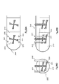
- FIG. 1 is a diagram showing a configuration example of a main part of an autoclave to which the present invention is applied.
- FIG. 1A is a plan view schematically showing the internal structure by horizontally cutting the autoclave.
- FIG. 1B is a plan view of the autoclave vertically cut.
- 1C is a side view schematically showing the internal structure, and
- FIG. 1C is a front view schematically showing the internal structure by cutting the autoclave vertically.
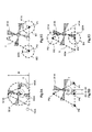
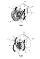
- FIG. 2 is a diagram schematically showing a procedure for determining the positions of the raw material slurry discharge port and the sulfuric acid discharge port in the autoclave, and FIGS. 2A, 2B, 2C, and 2D schematically illustrate the respective positions during the procedure. Show. Indicates FIG.
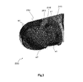
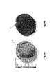
- FIG. 3 is a schematic diagram showing a stirring simulation result for a conventional autoclave before improvement.
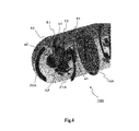
- FIG. 4 is a schematic diagram showing a stirring simulation result for an autoclave to which the present invention is applied.
- FIG. 5 is a diagram showing a simulation model of the arrangement of the slurry supply pipes
- FIG. 5A is a plan view of model A in which two slurry supply pipes are arranged along the side wall
- FIG. 5B is a diagram showing two slurry supply pipes. It is a top view of the model B arrange
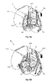
- FIG. 6 is a diagram showing a result of a simulation performed with flow lines that visualize the flow of the flow created only by the rotational force of the stirring blades in the autoclave.
- FIG. 6 is a diagram showing a result of a simulation performed with flow lines that visualize the flow of the flow created only by the rotational force of the stirring blades in the autoclave.
- FIG. 6A shows the flow in the compartment at the upstream end obliquely. The state seen from above is shown, and FIG. 6B shows the state seen from directly above.
- FIG. 7 is a schematic diagram showing a result of a simulation performed with flow lines visualizing the flow in an autoclave provided with a slurry supply pipe.
- FIG. 7A shows the flow in the upstream end compartment viewed from diagonally above.
- FIG. 7B shows a state viewed from directly above.
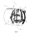
- FIG. 8 is a schematic diagram showing a simulation result of the model A shown by streamlines visualizing the flow of the slurry in the upstream compartment, and FIG. 8A shows the flow of slurry from the slurry supply pipe on the partition wall side.
- FIG. 8B shows a state in which slurry flows from the slurry supply pipe on the hemisphere side.
- FIG. 9 is a schematic diagram showing a result of a simulation performed on the model B indicated by streamlines visualizing the slurry flow in the upstream compartment.
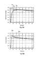
- FIG. 10 is a diagram showing a residence time distribution curve of the slurry in the models A and B
- FIG. 10A shows a result of calculating a residence time distribution curve of the slurry in the model A
- FIG. The result of calculating the residence time distribution curve is shown.
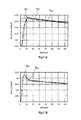
- FIG. 11 is a view showing a residence time distribution curve of sulfuric acid in the models A and B.
- FIG. 11A shows a result of calculating the residence time distribution curve of sulfuric acid in the model A
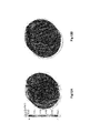
- FIG. 12 is a diagram showing the result of comparing the slurry residence time in the vicinity of the partition wall by performing a simulation indicated by streamlines visualizing the flow in the upstream end compartment for the models A and B.
- FIG. 12 The residence time of the slurry in the vicinity of the partition wall of model A is shown, and
- FIG. 12B shows the residence time of the slurry in the vicinity of the partition wall of model B.
- FIG. 13 is a vector diagram obtained as a result of simulating the flow in the cross section where the sulfuric acid supply pipe is installed.
- FIG. 14 is a diagram showing a result of a simulation for comparing the models A and B by coloring the streamline near the partition wall with sulfuric acid concentration, and FIG.
- FIG. 14A shows the sulfuric acid concentration near the partition wall in the model A.
- FIG. 14B shows the sulfuric acid concentration in the vicinity of the partition wall in the model B.
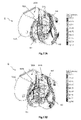
- FIG. 15 is a diagram showing a result of simulating the flow of sulfuric acid in a model C having a long sulfuric acid supply pipe and a model D having a short sulfuric acid supply pipe when the rotation speed of the stirring blade is 60.5 rpm.
- FIG. 15A shows the flow of sulfuric acid in model C
- FIG. 15B shows the flow of sulfuric acid in model D.
- FIG. 16 is a diagram showing a simulation result for a case where the rotation speed of the stirring blade showing the flow of sulfuric acid in Model E having a sulfuric acid supply pipe slightly longer than the short sulfuric acid supply pipe is 60.5 rpm.
- FIG. 17 is a diagram showing the temperature contour of the baffle and the stirring blade according to the length of the sulfuric acid supply pipe.
- FIG. 17A shows the temperature contour of the baffle and the stirring blade when the rotational speed of the stirring blade in Model C is 42.4 rpm.
- FIG. 17B shows a temperature contour of the baffle and the stirring blade when the rotational speed of the stirring blade in the model D is 42.4 rpm.
- FIG. 17A shows the temperature contour of the baffle and the stirring blade when the rotational speed of the stirring blade in Model C is 42.4 rpm.
- FIG. 17B shows a temperature contour of the baffle and the stirring blade when the rotational speed of the stirring blade in the model D is 42.4 rpm.
- FIG. 18 is a diagram illustrating a temperature contour of the baffle and the stirring blade in the case where the rotation speed of the stirring blade in the model E including the sulfuric acid supply tube slightly longer than the short sulfuric acid supply tube is 60.5 rpm.
- FIG. 19 is a process diagram showing the leaching procedure of nickel and cobalt by the high pressure acid leaching method of nickel oxide ore.
- FIG. 20 is a diagram showing a schematic structure of a general autoclave.
- FIG. 20A is a plan view schematically showing the internal structure by horizontally cutting the autoclave.
- FIG. 20B is a plan view schematically showing the internal structure by cutting the autoclave vertically.
- FIG. 20C is a front view schematically showing the internal structure by cutting the autoclave vertically.
- the present invention is implemented, for example, by an autoclave 100 having a structure as shown in FIG.
- FIG. 1 is a diagram showing a configuration of a main part of the autoclave 100.
- FIG. 1A is a plan view schematically showing the internal structure by cutting the autoclave 100 horizontally
- FIG. 1B is a diagram showing the autoclave 100 cut vertically.
- 1C is a side view schematically showing the internal structure
- FIG. 1C is a front view schematically showing the internal structure by cutting the autoclave 100 vertically.
- This autoclave 100 is an autoclave in a high-pressure acid leaching process in which heated and pressurized raw material slurry and sulfuric acid are agitated to leached valuable metals at high temperature and pressure, and is partitioned by partition walls 10A, 10B.
- the plurality of compartments 20A, 20B,... Are provided, and stirrers 30A, 30B,.
- leaching is advanced by stirring with the stirrers 30A, 30B... Provided in each of the compartments 20A, 20B.
- the slurry is transferred from the upstream compartment to the downstream compartment, and the leaching proceeds in sequence.
- the upstream end compartment 20A has a shape in which a hemisphere and a cylinder are combined, and the compartment 20B has a cylindrical shape in the middle.
- the autoclave 100 includes two raw slurry supply pipes 41 and 42 having raw slurry discharge ports 41A and 42A, respectively, around the stirring blade 31A of the stirrer 30A provided in the upstream end compartment 20A.
- Two sulfuric acid supply pipes 51 and 52 having sulfuric acid discharge ports 51A and 52A are alternately arranged.
- the raw slurry discharge ports 41A and 42A and the sulfuric acid discharge ports 51A and 52A are higher than the uppermost portion of the stirring blade 31A and lower than the content liquid level L.
- Each pipe is inserted into the autoclave 100 from above and has a steam pipe for maintaining the temperature at an arbitrary position.
- the stirring blade 31A of the stirrer 30A provided in the upstream end compartment 20A rotates clockwise to form a downward flow.
- the positions of the raw slurry discharge ports 41A and 42A and the sulfuric acid discharge ports 51A and 52A are determined as shown in FIG. 2, for example.
- an equilateral triangle T having a height of 0 to 0.5D is positioned so that the midpoint of the base is located downstream in the length direction of the base and in the rotation direction of the stirring blade 31A.
- the vertex positions P1, P2, P3 of the regular triangle T moved by the distance and the midpoint position P4 of the base are determined.
- the raw material slurry discharge ports 41A and 42A are positioned within a range S1 and S2 having a distance of 0.25D with the vertex positions P1 and P2 at both ends of the bottom side as centers. Then, as shown in FIG. 2D, the sulfuric acid discharge ports 51A, 52A have a distance range S3 of 0.25D centered on the remaining vertex position P3 of the regular triangle T and the midpoint position P4 of the bottom side, respectively. It is located in S4.
- raw slurry discharge ports 41A and 42A and the sulfuric acid discharge ports 51A and 52A are positioned higher than the uppermost portion of the stirring blade 31A and lower than the content liquid level L.
- 42 and two sulfuric acid supply pipes 51, 52 having sulfuric acid discharge ports 51A, 52A, respectively, raw material slurry and sulfuric acid are added to the upstream end compartment 20A.
- a stirring simulation was performed on the autoclave 100 having such a configuration.
- the slurry high-concentration portions a1 and a2 and the sulfuric acid high-concentration portions b1 and b2 existed over a wide range, and were in a state of poor diffusion.
- the simulation result shows that the slurry high concentration portions a1 and a2 and the sulfuric acid high concentration portions b1 and b2 are small and effectively diffused. I understand.
- a model A in which two slurry supply pipes 41 and 42 are arranged along the side wall as shown in FIG. 5A, and a direction orthogonal to the side wall as shown in FIG. 5B.
- the flow in the upstream compartment 20A of the autoclave 100 was analyzed by simulation for the model B in which two slurry supply pipes 43 and 44 are arranged along the line.
- FIG. 6A and FIG. 6B show the results of a simulation in which the flow in the compartment 20A is visualized with respect to the flow created by only the rotational force of the stirring blade without any slurry supply pipe.
- FIG. 6 there are two longitudinally rotating axial flows F1 and F2, and the surface S formed by the descending flow is located slightly hemispherically from the rotating shaft of the stirring blade 31A.
- FIGS. 7A and 7B A simulation was performed by adding a slurry supply pipe to such a model and visualizing the flow in the compartment 20A with streamlines. The results are shown in FIGS. 7A and 7B. As shown in FIG. 7, it can be seen that the surface S formed by the downward flow moves to the vicinity of the surface including the rotating shaft of the stirring blade 31A due to the baffle effect of the pipe.
- FIGS. 6A, 6B, 7A, and 7B show the flow in the compartment 20A at the upstream end as viewed obliquely from above (A) and the state as viewed from directly above (B).
- the tendency of the slurry flow is generally determined at the position where the slurry supply pipe is disposed.
- FIG. 8A in the case of model A, when the slurry is caused to flow from the slurry supply pipe 41 on the partition wall 10A side, a large flow is generated passing through between the stirring blade 31A and the baffle toward the hemispherical baffle 62. To do. Further, as shown in FIG. 8B, the slurry supply pipe 42 on the hemisphere side creates a rotational flow in the hemisphere portion. The slurry that flows from the slurry supply pipe 42 also appears to stay in the hemisphere, and there is a strong axial flow F2 around it as shown in FIGS. 6A and 6B. By adjusting the position of the slurry supply pipe 42, a stable slurry flow can be obtained.
- FIG. 9 shows the result of the simulation shown by the flow lines visualizing the flow in the compartment 20A for the model B shown in FIG. 5B.
- the slurry supply pipe 44 interposed on the side opposite to the side wall provided with the slurry supply pipes 41 and 42 creates a flow of slurry toward the partition wall 10A. Since the slurry flowing from the slurry supply pipe 44 approaches the partition wall 10A and directly flows, it leads to a short path of the slurry. Therefore, it is not preferable to dispose the slurry supply pipe 44 as in the model B.
- FIG. 10A shows the residence time distribution from the inlet to the outlet of the slurry in Model A.
- a distribution curve AP1 indicates the logical value of the slurry residence time distribution predicted by the complete mixing model
- a distribution curve AB1 indicates the slurry residence time distribution when the sulfuric acid supply pipe is short
- the distribution curve AG1 Shows the residence time distribution of the slurry when the sulfuric acid supply pipe is long.
- FIG. 10B shows the distribution of residence time from the inlet to the outlet of the slurry in model B as a distribution curve BB1.
- the distribution curve BP1 represents the logical value of the residence time distribution predicted by the complete mixing model.
- FIG. 11A shows the residence time distribution from the inlet to the outlet of sulfuric acid in Model A.
- a distribution curve AP2 indicates a logical value of the sulfuric acid residence time distribution predicted by the complete mixing model
- a distribution curve AB2 indicates a sulfuric acid residence time distribution when the sulfuric acid supply pipe is short
- a distribution curve AG2 Shows the residence time distribution of sulfuric acid when the sulfuric acid supply pipe is long.
- FIG. 11B shows the distribution of residence time from the inlet to the outlet of sulfuric acid in model B as a distribution curve BB2.
- the distribution curve BP2 shows the logical value of the residence time distribution predicted by the complete mixing model.
- the model B is faster than the logical value of the residence time distribution predicted by the complete mixing model indicated by the distribution curves AP1, BP1, AP2, and BP2.
- High concentrations of both slurry and sulfuric acid are observed in the time zone (10-30 seconds).
- model A a concentration higher than the logical value was not observed in an early time zone.
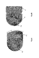
- FIG. 12A shows the residence time of the slurry in the vicinity of the partition wall 10A of model A.
- 12B shows the residence time of the slurry in the vicinity of the model B partition wall 10A.
- red r indicates a residence time of 15 seconds or less
- blue b indicates a residence time of 30 seconds or more.
- FIG. 12B has more red parts than FIG. 12A, and in Model B, it can be seen that there is a relatively large amount of slurry approaching the partition wall 10A in 15 seconds or less.
- This simulation result also shows that the arrangement of the slurry supply pipe 44 in the model B in which the slurry may flow directly in the vicinity of the partition wall is not preferable.
- FIG. 13 shows a vector diagram obtained as a result of simulating the flow in the cross section where the sulfuric acid supply pipe 51 is installed.
- FIGS. 14A and 14B The simulation results are shown in FIGS. 14A and 14B.
- FIG. 14A shows the sulfuric acid concentration in the vicinity of the partition wall 10A in the model A.
- FIG. 14B shows the sulfuric acid concentration in the vicinity of the partition wall 10A in the model B.
- the raw material slurry discharge ports 41A and 42A are arranged as the model B, and the sulfuric acid discharge ports 51A and 52A are arranged as the model A, and the stirring blades 31A of the stirrer provided in the compartment 20A.
- the raw slurry and sulfuric acid are alternately drawn toward the stirring blade 31A, thereby increasing the possibility of encounter and making the mixing proceed more efficiently than before.
- FIG. 17 (A) shows temperature contours of the baffles 61 to 63 and the stirring blade 31A when the rotational speed of the stirring blade 31A in the model C including the long sulfuric acid supply pipes 51L and 52L is 42.4 rpm.
- FIG. 17B shows temperature contours of the baffles 61 to 63 and the stirring blade 31A when the rotational speed of the stirring blade 31A is 42.4 rpm in the model D including the short sulfuric acid supply pipes 51S and 52S. .
- the supply pipes 41 and 42 and the two sulfuric acid supply pipes 51 and 52 having the sulfuric acid discharge ports 51A and 52A, respectively are positioned higher than the uppermost part of the stirring blade 31A and lower than the content liquid level L.
- the raw material slurry and sulfuric acid are added to the upstream end compartment 20A from the raw material slurry discharge ports 41A and 42A and the sulfuric acid discharge ports 51A and 52A.
- the autoclave 100 in which the raw material slurry and sulfuric acid are added to the upstream chamber 20A from the raw material slurry discharge ports 41A and 42A and the sulfuric acid discharge ports 51A and 52A, particularly in the case of nickel oxide ore treatment.
- the conditions such as the solid content of the slurry, the viscosity, the temperature of the autoclave overlap, and the raw slurry and sulfuric acid are alternately drawn toward the stirring blade 31A, and the possibility of encounter is increased. Therefore, the mixing proceeds more efficiently than before, and the leaching rate is improved.
- the contact with the wall surface of high concentration sulfuric acid can be prevented, and the damage of the wall surface by the contact with high concentration sulfuric acid can be reduced.
- the concentration of free sulfuric acid in the leachate is not 50 to 55 g / L, the predetermined leach rate of 90 to 95% could not be maintained.
- the concentration of free sulfuric acid in the leachate Even if it is controlled to 45 to 50 g / L, a predetermined leaching rate can be maintained.
- the positions of the raw material slurry discharge ports 41A, 42A and the sulfuric acid discharge ports 51A, 52A are not particularly limited to the positional relationship with the autoclave 100, and the stirring blades of the stirrer 30A provided in the upstream compartment 20A.
- An arbitrary position can be selected by rotating around the center of 31A.
- the raw material slurry discharge ports 41A and 42A and the sulfuric acid discharge ports 51A and 52A are not drawn in alternation when positioned outside the defined ranges S1, S2, S3, and S4. This is not preferable because the flow is too close or too far away and the efficiency of the above mixing deteriorates.
- the direction of the bottom side of the regular triangle T is parallel to the side wall of the autoclave 100.
- the raw material slurry discharge ports 41A and 42A are positioned parallel to the side wall of the autoclave, so that the piping is relatively short, and furthermore, the degree of crossing and overlapping when piping is laid is the smallest. Is also preferable because of its simplicity.
- Example 1 The operation was performed with the pressure in the autoclave being 5.5 MPaG, the temperature being 250 ° C., the Ni grade in the ore being 1.0 to 1.4%, and the amount of slurry flowing into the autoclave being about 300 to 700 m 3 / hour. At this time, the present invention was applied to supply ore slurry and sulfuric acid.
- the leaching rate of nickel was 92.5%.
- the concentration of free sulfuric acid in the leachate could be controlled and operated at 45 to 50 g / L.
- the leaching rate of nickel was 92.0%.
- the concentration of free sulfuric acid in the leachate is controlled at 50 to 55 g / L, the above leach rate could not be maintained.
Landscapes
- Chemical & Material Sciences (AREA)
- Chemical Kinetics & Catalysis (AREA)
- Organic Chemistry (AREA)
- Engineering & Computer Science (AREA)
- Manufacturing & Machinery (AREA)
- Materials Engineering (AREA)
- Metallurgy (AREA)
- Mechanical Engineering (AREA)
- Environmental & Geological Engineering (AREA)
- Geochemistry & Mineralogy (AREA)
- General Life Sciences & Earth Sciences (AREA)
- Geology (AREA)
- Life Sciences & Earth Sciences (AREA)
- Inorganic Chemistry (AREA)
- Manufacture And Refinement Of Metals (AREA)
- Mixers Of The Rotary Stirring Type (AREA)
- Accessories For Mixers (AREA)
- Extraction Or Liquid Replacement (AREA)
Description
本発明は、例えば図1に示すような構造のオートクレーブ100により実施される。
ここで、上述したオートクレーブ100における原料スラリー吐出口41A,42Aを有する原料スラリー供給管41,42と、硫酸吐出口51A,52Aを有する硫酸供給管51,52の設置位置は、安定したオートクレーブ操業を行うために、
(1) 良好な混合性を維持する。
(2) 反応槽での浸出反応のために一定の滞留時間を確保する。
(3) 酸により設備ダメージを回避する。
という3つの条件を満たすように、次のようなシミュレーションに基づいて決定される。
以下具体的に説明する。
上述の如き構造のオートクレーブ100において、浸出反応が十分に進むためには、半球と円筒を結合した形状の上流端の区画室20Aで、良好な混合性を維持し、且つ、一定の滞留時間が必要となる。また、硫酸や蒸気に比べスラリーは流量が多いので、オートクレーブ100内の流れの傾向を決定するのは、撹拌翼31Aの回転力によるスラリーの流れが持つ運動エネルギーである。
次に、硫酸供給管の設置位置について検討する。この検討にあたっては、硫酸供給管から供給される硫酸による隔壁10Aへのダメージの可能性の観点から、上述のモデルA,Bについて、隔壁10A付近の流線に硫酸濃度で着色して比較するシミュレーションを行った。
次に、硫酸供給管の長さについて検討する。先ず、長尺の硫酸供給管51L、52Lを備えるモデルCと、短尺の硫酸供給管51S、52Sを備えるモデルDにおける硫酸の流れを、撹拌翼31Aの回転数が60.5rpmの場合についてシミュレーションした。その結果を、図15A,図15Bに示す。
オートクレーブ内の圧力が5.5MPaG、温度が250℃、鉱石中Ni品位が1.0~1.4%、オートクレーブへのスラリー流入量が300~700m3/時間程度の操業を行った。この際、本発明を適用して、鉱石スラリーおよび硫酸を供給した。
本発明を適用せず、図20に示した従来のオートクレーブにおける従来方法で、鉱石スラリー及び硫酸を供給したこと以外は、実施例1と同様に操業した。
Claims (6)
- 加熱、加圧された原料スラリー及び硫酸を、隔壁で複数に区画されたオートクレーブ内の各区画室に備えられた撹拌機によって撹拌することにより浸出を進行させ、上流側の区画室から下流側の区画室にスラリーを移送し、順次、浸出を進行させる高圧酸浸出工程におけるオートクレーブへの原料スラリーと硫酸の添加方法であって、
上記オートクレーブの上流端の区画室に備えられた撹拌機の撹拌翼の周囲に交互に配された原料スラリー吐出口を有する原料スラリー供給管と、硫酸吐出口を有する硫酸供給管を介して、上記撹拌翼の最上部より高く、内容物液面より低い位置に位置させた上記原料スラリー吐出口及び硫酸吐出口から上記上流端の区画室に原料スラリーと硫酸を添加することを特徴とするオートクレーブへの原料スラリーと硫酸の添加方法。 - 上記原料スラリー吐出口及び硫酸吐出口は、その平面位置において、上記撹拌翼の端部が形成する円の任意の直径Dを高さとする正三角形の底辺の長さ方向であって上記撹拌翼の回転方向の下流側に上記底辺の中点が位置するよう0Dから0.5Dの距離だけ移動させた上記正三角形の底辺の両端の頂点位置をそれぞれ中心にして0.25Dの距離の範囲内に原料スラリー吐出口が位置され、上記底辺の中点位置と上記正三角形の残りの頂点位置をそれぞれ中心にして上記直径の0.25Dの距離の範囲内に硫酸吐出口が位置されて、上記原料スラリー吐出口及び硫酸吐出口から上記上流端の区画室に原料スラリーと硫酸を添加することを特徴とする請求項1記載のオートクレーブへの原料スラリーと硫酸の添加方法。
- 上記正三角形の底辺の長さ方向は、オートクレーブの側壁と平行であることを特徴とする請求項2記載のオートクレーブへの原料スラリーと硫酸の添加方法。
- 加熱、加圧された原料スラリー及び硫酸を、隔壁で複数に区画されたオートクレーブ内の各区画室に備えられた撹拌機によって撹拌することにより浸出を進行させ、上流側の区画室から下流側の区画室にスラリーを移送し、順次、浸出を進行させる高圧酸浸出工程におけるオートクレーブであって、
上流端の区画室に備えられた撹拌機の撹拌翼の周囲に、原料スラリー吐出口を有する原料スラリー供給管と、硫酸吐出口を有する硫酸供給管を交互に配し、上記撹拌翼の最上部より高く、内容物液面より低い位置に上記原料スラリー吐出口及び硫酸吐出口を位置させてなり、
上記原料スラリー供給管と硫酸供給管を介して、上記上流端の区画室に備えられた撹拌機の撹拌翼の最上部より高く、内容物液面より低い位置に、上記撹拌翼の周囲に交互に位置させた上記原料スラリー吐出口及び硫酸吐出口から上記上流端の区画室に原料スラリーと硫酸が添加されることを特徴とするオートクレーブ。 - 上記原料スラリー吐出口及び硫酸吐出口は、その平面位置において、上記撹拌翼の端部が形成する円の任意の直径を高さとする正三角形の底辺の長さ方向であって上記撹拌翼の回転方向の下流側に上記底辺の中点が位置するよう0Dから0.5Dの距離だけ移動させた上記正三角形の底辺の両端の頂点位置をそれぞれ中心にして0.25Dの距離の範囲内に原料スラリー吐出口が位置され、上記底辺の中点位置と上記正三角形の残りの頂点位置をそれぞれ中心にして0.25Dの距離の範囲内に硫酸吐出口が位置されたことを特徴とする請求項4記載のオートクレーブ。
- 上記正三角形の底辺の長さ方向は、当該オートクレーブの側壁と平行であることを特徴とする請求項5記載のオートクレーブ。
Priority Applications (5)
| Application Number | Priority Date | Filing Date | Title |
|---|---|---|---|
| EP13782392.8A EP2843064B1 (en) | 2012-04-26 | 2013-04-15 | Method for adding starting material slurry and sulfuric acid to an autoclave in high pressure acid leaching process and autoclave |
| US14/396,300 US9970077B2 (en) | 2012-04-26 | 2013-04-15 | Method for adding starting material slurry and sulfuric acid to autoclave in high pressure acid leaching process and autoclave |
| CA2871604A CA2871604C (en) | 2012-04-26 | 2013-04-15 | Method for adding starting material slurry and sulfuric acid to autoclave in high pressure acid leaching process and autoclave |
| AU2013253807A AU2013253807B2 (en) | 2012-04-26 | 2013-04-15 | Method for adding starting material slurry and sulfuric acid to autoclave in high pressure acid leaching process and autoclave |
| PH12014502354A PH12014502354B1 (en) | 2012-04-26 | 2014-10-21 | Method for adding starting material slurry and sulfuric acid to autoclave in high pressure acid leaching process and autoclave |
Applications Claiming Priority (4)
| Application Number | Priority Date | Filing Date | Title |
|---|---|---|---|
| JP2012-101614 | 2012-04-26 | ||
| JP2012101614 | 2012-04-26 | ||
| JP2012-260286 | 2012-11-28 | ||
| JP2012260286A JP5387755B2 (ja) | 2012-04-26 | 2012-11-28 | 高圧酸浸出工程におけるオートクレーブへの原料スラリーと硫酸の添加方法及びオートクレーブ |
Publications (1)
| Publication Number | Publication Date |
|---|---|
| WO2013161599A1 true WO2013161599A1 (ja) | 2013-10-31 |
Family
ID=49482923
Family Applications (1)
| Application Number | Title | Priority Date | Filing Date |
|---|---|---|---|
| PCT/JP2013/061158 Ceased WO2013161599A1 (ja) | 2012-04-26 | 2013-04-15 | 高圧酸浸出工程におけるオートクレーブへの原料スラリーと硫酸の添加方法及びオートクレーブ |
Country Status (7)
| Country | Link |
|---|---|
| US (1) | US9970077B2 (ja) |
| EP (1) | EP2843064B1 (ja) |
| JP (1) | JP5387755B2 (ja) |
| AU (1) | AU2013253807B2 (ja) |
| CA (1) | CA2871604C (ja) |
| PH (1) | PH12014502354B1 (ja) |
| WO (1) | WO2013161599A1 (ja) |
Cited By (2)
| Publication number | Priority date | Publication date | Assignee | Title |
|---|---|---|---|---|
| CN104561536A (zh) * | 2014-12-25 | 2015-04-29 | 中国恩菲工程技术有限公司 | 浸出釜 |
| CN109078354A (zh) * | 2018-09-23 | 2018-12-25 | 天津市艾碘科技股份有限公司 | 一种工业粗碘回收搅拌装置 |
Families Citing this family (15)
| Publication number | Priority date | Publication date | Assignee | Title |
|---|---|---|---|---|
| JP5700029B2 (ja) * | 2012-12-11 | 2015-04-15 | 住友金属鉱山株式会社 | 硫化水素を含む貧液の処理方法及び処理装置 |
| CN106621448A (zh) * | 2015-11-01 | 2017-05-10 | 江苏景泰石油化工装备有限公司 | 高效夹套式加热浸出罐 |
| JP6905211B2 (ja) * | 2017-07-24 | 2021-07-21 | 住友金属鉱山株式会社 | オートクレーブ |
| JP6589950B2 (ja) * | 2017-08-16 | 2019-10-16 | 住友金属鉱山株式会社 | 浸出処理方法、ニッケル酸化鉱石の湿式製錬方法 |
| KR101889681B1 (ko) | 2018-02-13 | 2018-08-17 | 고려아연 주식회사 | 오토클레이브 및 오토클레이브의 염 제거방법 |
| CN108706572B (zh) * | 2018-06-12 | 2021-05-28 | 合肥科塑信息科技有限公司 | 一种石墨烯基复合材料制取设备 |
| CN109022765B (zh) * | 2018-08-22 | 2020-07-14 | 贵州大学 | 一种搅拌浸出槽 |
| JP7285427B2 (ja) * | 2019-07-16 | 2023-06-02 | 住友金属鉱山株式会社 | ニッケル酸化鉱石の浸出処理方法 |
| CN110605090B (zh) * | 2019-09-17 | 2021-07-30 | 义乌市倩飞科技有限公司 | 一种乙烯法聚氯乙烯乳液饱和梯度缩合的本体聚合系统 |
| US20240110258A1 (en) * | 2019-10-15 | 2024-04-04 | Metso Outotec Finland Oy | Autoclave and pressure oxidation method |
| JP2022104019A (ja) * | 2020-12-28 | 2022-07-08 | 住友金属鉱山株式会社 | 中和処理方法、ニッケル酸化鉱石の湿式製錬方法 |
| CN113999968B (zh) * | 2022-01-04 | 2022-06-07 | 中国恩菲工程技术有限公司 | 高压釜加酸系统及控制方法 |
| AU2023446744A1 (en) * | 2023-06-29 | 2025-02-06 | Gem Co., Ltd. | High-pressure reactor |
| DE102024114537A1 (de) * | 2024-05-23 | 2025-11-27 | EKATO Rühr- und Mischtechnik GmbH | Autoklavvorrichtung und Autoklav |
| WO2026083368A1 (en) * | 2024-10-14 | 2026-04-23 | Pt Esg New Energy Material | High-pressure reactor with adjustable baffles |
Citations (6)
| Publication number | Priority date | Publication date | Assignee | Title |
|---|---|---|---|---|
| JPH02197533A (ja) * | 1989-01-25 | 1990-08-06 | Sumitomo Metal Mining Co Ltd | 有価金属の分離方法 |
| JPH0784623B2 (ja) | 1984-09-19 | 1995-09-13 | シエリツト・ゴ−ドン・マインズ・リミテツド | 非鉄金属含有硫化物材料からの非鉄金属回収方法 |
| JP2005350766A (ja) | 2004-05-13 | 2005-12-22 | Sumitomo Metal Mining Co Ltd | ニッケル酸化鉱石の湿式製錬方法 |
| JP2009515044A (ja) | 2005-11-10 | 2009-04-09 | コンパニア バレ ド リオ ドセ | 複合浸出プロセス |
| JP2009530077A (ja) * | 2006-03-17 | 2009-08-27 | バリック・ゴールド・コーポレイション | 底流仕切部材を備えたオートクレーブ |
| JP2011241446A (ja) * | 2010-05-18 | 2011-12-01 | Sumitomo Metal Mining Co Ltd | 硫化反応工程の反応制御方法 |
Family Cites Families (14)
| Publication number | Priority date | Publication date | Assignee | Title |
|---|---|---|---|---|
| GB808609A (en) | 1956-05-15 | 1959-02-04 | Hercules Powder Co Ltd | Improvements in or relating to process and apparatus for the continuous manufacture of nitrocellulose |
| DE1091568B (de) * | 1957-08-02 | 1960-10-27 | Bergwerksgesellschaft Hibernia | Verfahren und Vorrichtung zur kontinuierlichen Durchfuehrung von Reaktionen zwischen Gasen und Fluessigkeiten |
| US3121759A (en) * | 1960-08-23 | 1964-02-18 | Kellogg M W Co | Cascade liquid-vapor reactor |
| US3961908A (en) * | 1974-02-27 | 1976-06-08 | Freeport Minerals Company | Autoclave system for leaching sulfide concentrates |
| US5071477A (en) * | 1990-05-03 | 1991-12-10 | American Barrick Resources Corporation of Toronto | Process for recovery of gold from refractory ores |
| JPH0784623A (ja) | 1993-09-14 | 1995-03-31 | Zexel Corp | Cad/cam結合システム |
| US5535992A (en) * | 1995-03-07 | 1996-07-16 | Goro Nickel S.A. | Apparatus and method for acidic leaching of lateritic ores |
| US5856533A (en) | 1995-12-28 | 1999-01-05 | Praxair Technology, Inc. | High efficiency heat and mass transfer for vapor phase heterogeneous reactions |
| US6299776B1 (en) * | 1997-12-23 | 2001-10-09 | General Signal Corporation | Biochemical oxidation system and process |
| US6368381B1 (en) * | 1998-03-11 | 2002-04-09 | Placer Dome Technical Services, Ltd. | Autoclave using agitator and sparge tube to provide high oxygen transfer rate to metal-containing solutions |
| US6835230B2 (en) * | 2001-03-28 | 2004-12-28 | Dowa Mining Co., Ltd. | Method for leaching zinc concentrate |
| FI20060712A7 (fi) * | 2004-01-07 | 2006-09-15 | Hydromet Pty Ltd | Eksotermiset paineliuotusautoklaavin kierrot |
| US7604783B2 (en) * | 2004-12-22 | 2009-10-20 | Placer Dome Technical Services Limited | Reduction of lime consumption when treating refractor gold ores or concentrates |
| BE1019347A3 (fr) * | 2010-05-25 | 2012-06-05 | Forrest George Arthur | Reacteur hydrometallurgique. |
-
2012
- 2012-11-28 JP JP2012260286A patent/JP5387755B2/ja active Active
-
2013
- 2013-04-15 CA CA2871604A patent/CA2871604C/en not_active Expired - Fee Related
- 2013-04-15 US US14/396,300 patent/US9970077B2/en active Active
- 2013-04-15 AU AU2013253807A patent/AU2013253807B2/en active Active
- 2013-04-15 WO PCT/JP2013/061158 patent/WO2013161599A1/ja not_active Ceased
- 2013-04-15 EP EP13782392.8A patent/EP2843064B1/en not_active Not-in-force
-
2014
- 2014-10-21 PH PH12014502354A patent/PH12014502354B1/en unknown
Patent Citations (6)
| Publication number | Priority date | Publication date | Assignee | Title |
|---|---|---|---|---|
| JPH0784623B2 (ja) | 1984-09-19 | 1995-09-13 | シエリツト・ゴ−ドン・マインズ・リミテツド | 非鉄金属含有硫化物材料からの非鉄金属回収方法 |
| JPH02197533A (ja) * | 1989-01-25 | 1990-08-06 | Sumitomo Metal Mining Co Ltd | 有価金属の分離方法 |
| JP2005350766A (ja) | 2004-05-13 | 2005-12-22 | Sumitomo Metal Mining Co Ltd | ニッケル酸化鉱石の湿式製錬方法 |
| JP2009515044A (ja) | 2005-11-10 | 2009-04-09 | コンパニア バレ ド リオ ドセ | 複合浸出プロセス |
| JP2009530077A (ja) * | 2006-03-17 | 2009-08-27 | バリック・ゴールド・コーポレイション | 底流仕切部材を備えたオートクレーブ |
| JP2011241446A (ja) * | 2010-05-18 | 2011-12-01 | Sumitomo Metal Mining Co Ltd | 硫化反応工程の反応制御方法 |
Non-Patent Citations (1)
| Title |
|---|
| See also references of EP2843064A4 |
Cited By (2)
| Publication number | Priority date | Publication date | Assignee | Title |
|---|---|---|---|---|
| CN104561536A (zh) * | 2014-12-25 | 2015-04-29 | 中国恩菲工程技术有限公司 | 浸出釜 |
| CN109078354A (zh) * | 2018-09-23 | 2018-12-25 | 天津市艾碘科技股份有限公司 | 一种工业粗碘回收搅拌装置 |
Also Published As
| Publication number | Publication date |
|---|---|
| PH12014502354B1 (en) | 2019-04-26 |
| US20150086450A1 (en) | 2015-03-26 |
| CA2871604C (en) | 2019-04-09 |
| EP2843064B1 (en) | 2018-09-05 |
| PH12014502354A1 (en) | 2015-01-12 |
| EP2843064A1 (en) | 2015-03-04 |
| JP2013241668A (ja) | 2013-12-05 |
| AU2013253807A1 (en) | 2014-11-13 |
| AU2013253807B2 (en) | 2017-03-02 |
| US9970077B2 (en) | 2018-05-15 |
| EP2843064A4 (en) | 2015-12-30 |
| JP5387755B2 (ja) | 2014-01-15 |
| CA2871604A1 (en) | 2013-10-31 |
Similar Documents
| Publication | Publication Date | Title |
|---|---|---|
| JP5387755B2 (ja) | 高圧酸浸出工程におけるオートクレーブへの原料スラリーと硫酸の添加方法及びオートクレーブ | |
| JP5418660B2 (ja) | 高圧酸浸出工程におけるオートクレーブ装置 | |
| JP5500304B2 (ja) | 高圧酸浸出工程におけるオートクレーブ装置 | |
| JP2016011442A (ja) | オートクレーブ及びオートクレーブへのガス吹込み方法 | |
| JP6593191B2 (ja) | 浸出槽 | |
| EP4516390B1 (en) | High-pressure reactor | |
| JP5482955B2 (ja) | 高圧酸浸出工程におけるオートクレーブへの原料スラリーと硫酸の添加方法及びオートクレーブ | |
| JP2014113564A (ja) | 撹拌反応装置 | |
| JP6848507B2 (ja) | 加圧反応装置、及びそれを用いた有価金属の浸出処理方法 | |
| CN214514423U (zh) | 高压釜 | |
| JP7180086B2 (ja) | 加圧反応装置、及びそれを用いた有価金属の浸出処理方法 | |
| Marsden et al. | Medium-temperature pressure leaching of copper concentrates—Part II: Development of direct electrowinning and an acid-autogenous process | |
| JP7396072B2 (ja) | 混合装置及び混合方法 | |
| JP7447471B2 (ja) | 攪拌装置 | |
| JP6836151B2 (ja) | 加圧反応装置、及びそれを用いた有価金属の浸出処理方法 | |
| JP2018071918A (ja) | 向流式直接加熱型熱交換器 | |
| Nicolle et al. | Mixing system design for the Tati Activox® autoclave | |
| CN223490723U (zh) | 氧压浸出系统 | |
| JP6790626B2 (ja) | オートクレーブ装置 | |
| JP2022178938A (ja) | オートクレーブ装置 | |
| JP2022178997A (ja) | オートクレーブ装置 | |
| CN104120251B (zh) | 提高目标元素转浸率的湿法冶金反应器和湿法冶金方法 | |
| CN103285801A (zh) | 一种反应釜 | |
| CN104209510A (zh) | 串联式精细鳞片化组合装置 |
Legal Events
| Date | Code | Title | Description |
|---|---|---|---|
| 121 | Ep: the epo has been informed by wipo that ep was designated in this application |
Ref document number: 13782392 Country of ref document: EP Kind code of ref document: A1 |
|
| WWE | Wipo information: entry into national phase |
Ref document number: 14396300 Country of ref document: US |
|
| ENP | Entry into the national phase |
Ref document number: 2871604 Country of ref document: CA |
|
| WWE | Wipo information: entry into national phase |
Ref document number: 2013782392 Country of ref document: EP |
|
| NENP | Non-entry into the national phase |
Ref country code: DE |
|
| ENP | Entry into the national phase |
Ref document number: 2013253807 Country of ref document: AU Date of ref document: 20130415 Kind code of ref document: A |
|
| WWE | Wipo information: entry into national phase |
Ref document number: IDP00201407349 Country of ref document: ID |