WO2013161962A1 - Structure de montage de dispositif électrique - Google Patents
Structure de montage de dispositif électrique Download PDFInfo
- Publication number
- WO2013161962A1 WO2013161962A1 PCT/JP2013/062286 JP2013062286W WO2013161962A1 WO 2013161962 A1 WO2013161962 A1 WO 2013161962A1 JP 2013062286 W JP2013062286 W JP 2013062286W WO 2013161962 A1 WO2013161962 A1 WO 2013161962A1
- Authority
- WO
- WIPO (PCT)
- Prior art keywords
- slide
- mounting
- slide portion
- attachment
- protruding position
- Prior art date
- Legal status (The legal status is an assumption and is not a legal conclusion. Google has not performed a legal analysis and makes no representation as to the accuracy of the status listed.)
- Ceased
Links
Images




Classifications
-
- H—ELECTRICITY
- H02—GENERATION; CONVERSION OR DISTRIBUTION OF ELECTRIC POWER
- H02B—BOARDS, SUBSTATIONS OR SWITCHING ARRANGEMENTS FOR THE SUPPLY OR DISTRIBUTION OF ELECTRIC POWER
- H02B1/00—Frameworks, boards, panels, desks, casings; Details of substations or switching arrangements
- H02B1/015—Boards, panels, desks; Parts thereof or accessories therefor
- H02B1/04—Mounting thereon of switches or of other devices in general, the switch or device having, or being without, casing
- H02B1/042—Mounting on perforated supports by means of screws or locking members
-
- H—ELECTRICITY
- H02—GENERATION; CONVERSION OR DISTRIBUTION OF ELECTRIC POWER
- H02B—BOARDS, SUBSTATIONS OR SWITCHING ARRANGEMENTS FOR THE SUPPLY OR DISTRIBUTION OF ELECTRIC POWER
- H02B1/00—Frameworks, boards, panels, desks, casings; Details of substations or switching arrangements
- H02B1/015—Boards, panels, desks; Parts thereof or accessories therefor
- H02B1/04—Mounting thereon of switches or of other devices in general, the switch or device having, or being without, casing
- H02B1/052—Mounting on rails
- H02B1/0523—Mounting on rails locked into position by a sliding member
-
- H—ELECTRICITY
- H05—ELECTRIC TECHNIQUES NOT OTHERWISE PROVIDED FOR
- H05K—PRINTED CIRCUITS; CASINGS OR CONSTRUCTIONAL DETAILS OF ELECTRIC APPARATUS; MANUFACTURE OF ASSEMBLAGES OF ELECTRICAL COMPONENTS
- H05K7/00—Constructional details common to different types of electric apparatus
- H05K7/14—Mounting supporting structure in casing or on frame or rack
- H05K7/1462—Mounting supporting structure in casing or on frame or rack for programmable logic controllers [PLC] for automation or industrial process control
- H05K7/1474—Mounting of modules, e.g. on a base or rail or wall
Definitions
- the present invention relates to an electrical equipment mounting structure.
- electric devices such as a programmable controller (PLC), a relay, a timer, or a breaker are attached to a mounting surface such as a support rail or a wall surface.
- a mounting surface such as a support rail or a wall surface.
- a first fastener and a second fastener that are slidable in the same sliding direction are provided on the back surface of a base of an electronic device main body, and are connected to a support rail. Is attached to a position where the tip of the first fastener engages with the support rail.
- Each of the first and second fasteners has a screw hole, and when the screw hole is slid to a position protruding from the base, it is also locked at that position. Thereby, attachment to a support plate etc. is also attained.
- the first and second fasteners that are the slide portions are provided with arc-shaped elastic locking pieces that project so as to be cantilevered, and the base that is the mounting body
- the locking piece is locked in the locking hole formed on the back surface of the plate, and the slide portion is locked.
- the slide part may be unlocked by coming off the stop hole. Therefore, when the electric device is mounted on the mounting surface using the screw holes provided in the two slide portions (that is, in the case of direct mounting), when the slide portion is unlocked, the electric device is attached to the mounting body. At the same time, it may come off the mounting surface.
- the present invention is directed to an electric equipment mounting structure, and an object of the present invention is to firmly fix the slide portion to the mounting body in the case of direct mounting.
- the mounting structure for an electrical device includes a mounting body that supports or accommodates the electrical device, and a slide portion that is movable in a sliding direction along the bottom surface by a guide portion provided on the bottom surface of the mounting body.
- a slide portion that is movable in a sliding direction along the bottom surface by a guide portion provided on the bottom surface of the mounting body.
- the slide portion in the case of direct mounting on the mounting surface, can be firmly fixed to the mounting body.
- the electric device mounting structure further includes another slide portion that is movable in a sliding direction along the bottom surface by another guide portion provided on the bottom surface.
- One slide portion is formed on the bottom surface when the other slide portion is disposed at a through hole for inserting a mounting screw and the projecting position where the through hole is located outside the side surface of the mounting body.
- a state in which the other slide part is disposed at the projecting position and the attachment body is directly attached to the attachment surface.
- Both sides of the slide engagement portion in a direction perpendicular to the bottom surface are in direct or indirect contact with the protruding position locking portion and the mounting surface.
- the slide direction of the slide portion is different from the slide direction of the other slide portion.
- the electric device mounting structure is movable along the bottom surface and in a sliding direction different from the sliding direction by another guide portion provided on the bottom surface.
- a slide portion, and a rail engagement portion that is provided on the bottom surface and engages with one edge along the longitudinal direction of the support rail when the attachment main body is attached to a long support rail,
- the slide portion is arranged at the protruding position, and the through hole for inserting the mounting screw formed in the other slide portion is outside the side surface of the mounting body.
- the slide part and the other slide part One ride portion is disposed in the rail engaging position to the other edge engages along the longitudinal direction of the support rail.
- the slide part when the slide part is disposed at the projecting position, the slide part is engaged with another projecting position locking part having a convex shape or a concave shape formed on the bottom surface.
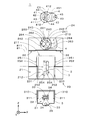
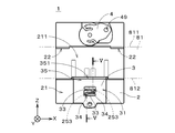
- FIG. 1 It is a perspective view which shows the attachment structure of an electric equipment. It is an exploded view of an attachment structure. It is a perspective view of an attachment structure. It is a bottom view of an attachment structure. It is sectional drawing of an attachment structure. It is a bottom view of an attachment structure. It is sectional drawing of an attachment structure. It is a bottom view of the attachment structure. It is sectional drawing of an attachment structure. It is a bottom view of the attachment structure of a comparative example. It is sectional drawing of the attachment structure of a comparative example. It is sectional drawing of the other example of an attachment structure.
- FIG. 1 is a perspective view showing a mounting structure 1 for an electric device 9 according to an embodiment of the present invention.
- the electrical device 9 is, for example, a programmable controller (PLC), a relay, a timer, or a breaker.
- the mounting structure 1 includes a box-shaped mounting body 2 in which an electrical device 9 is accommodated, and a first slide portion 3 is provided on one surface 21 (the ( ⁇ Y) side surface in FIG. 1) of the mounting body 2. And the 2nd slide part 4 is provided.
- the attachment main body 2, the first slide part 3, and the second slide part 4 are made of, for example, resin.
- the surface 21 When mounting the mounting structure 1 to a support rail or mounting surface, which will be described later, the surface 21 is often mounted so as to stand upright (of course, it may be mounted in another posture), but mounting before mounting. Since the structure 1 is often handled with the surface 21 facing downward in the vertical direction, the surface 21 of the mounting body 2 is referred to as a “bottom surface 21” in the following description.
- a bottom surface 21 In FIG. 1, two directions substantially along the bottom surface 21 and orthogonal to each other are shown as an X direction and a Z direction, and a direction substantially perpendicular to the bottom surface 21 is shown as a Y direction (the same applies hereinafter).
- the bottom surface 21 has a rectangular outer shape having sides parallel to the X direction and the Z direction.
- FIG. 2 is an exploded view of the mounting structure 1.
- the mounting body 2, the first slide portion 3, and the second slide portion 4 are separated and viewed from the ( ⁇ Y) side in FIG. 1 toward the (+ Y) direction. It shows the state.
- a groove 211 (hereinafter referred to as a “rail groove 211”) extending in the horizontal direction (X direction) in FIG.
- the support rail 81 has a rail groove. 211 is fitted.
- the first slide portion 3 and the second slide portion 4 are arranged on the ( ⁇ Z) side and the (+ Z) side of the rail groove 211, respectively. That is, the rail groove 211 is formed between the first slide portion 3 and the second slide portion 4.
- two rail engaging portions 22 projecting to the ( ⁇ Z) side are formed at the (+ Z) side edge of the rail groove 211.
- the two rail engaging portions 22 are arranged at both end portions of the rail groove 211 in the X direction.
- a groove 212 extending in the ( ⁇ Z) direction from the center of the rail groove 211 in the X direction (a groove used for movement of the first slide portion 3, hereinafter referred to as “slide groove 212”). ) Is formed. Further, a protrusion 231 protruding to the (+ X) side is formed at the ( ⁇ X) side edge of the slide groove 212, and a protrusion protruding to the ( ⁇ X) side at the (+ X) side edge of the slide groove 212. A portion 231 is formed.
- both end portions 310 in the X direction are thinner than other portions, and both end portions 310 are bottom surfaces of the slide grooves 212 (surfaces perpendicular to the Y direction).
- the protrusions 231 (see FIG. 1).
- the first guide portion 23 including the two protrusion portions 231 extends along the bottom surface 21 of the mounting body 2 and the slide groove 212 extends (that is, the Z direction, hereinafter referred to as “first slide direction”). .) Is supported so as to be movable.
- the ( ⁇ Y) side surface of the first slide portion 3 supported by the first guide portion 23 is substantially flush with the area of the bottom surface 21 excluding grooves 211 and 212 and a later-described recess 213. To position.
- a portion 311 that slightly protrudes to the (+ Y) side is formed in the vicinity of both end portions 310 of the first slide portion 3 shown in FIG. 2, and two portions for sliding the portion 311 on the bottom surface of the slide groove 212 are formed.
- An auxiliary groove 251 is formed. Between the two auxiliary grooves 251, two other auxiliary grooves 252 that are used when the first slide portion 3 is attached to the attachment body 2 are formed, and each auxiliary groove 252 has 2 on the ( ⁇ Z) side. Two grooves 253 and 254 are formed side by side in the Z direction.
- the main body 31 of the first slide part 3 has an opening 32 at the center, and the outer shape of the opening 32 is substantially rectangular.
- a long member 33 protruding to the (+ X) side is formed at the ( ⁇ X) side edge of the opening 32, and the tip of the long member 33 is disposed in the vicinity of the (+ X) side edge of the opening 32.
- a long member 33 protruding to the ( ⁇ X) side is formed at the (+ X) side edge of the opening 32, and the tip of the long member 33 is near the ( ⁇ X) side edge of the opening 32. Be placed.
- the leaf spring-like two long members 33 extending in the X direction and supported in a cantilever state are formed in the opening 32 of the first slide portion 3 side by side in the Z direction.
- the A slide engagement portion 34 is formed in the vicinity of the free end of each long member 33, and the slide engagement portion 34 slightly protrudes to the (+ Y) side from the main body 31 and the long member 33.
- the first slide portion 3 When the first slide portion 3 is attached to the attachment body 2, the first slide portion 3 is disposed on the (+ Z) side of the first guide portion 23 as shown by a two-dot chain line in FIG.
- both end portions 310 By moving the slide portion 3 in the ( ⁇ Z) direction, both end portions 310 are inserted between the bottom surface of the slide groove 212 and both the protrusion portions 231.
- the part 311 of each end 310 slides in the auxiliary groove 251, and each slide engagement part 34 slides in the auxiliary groove 252.
- the slide engaging portion 34 reaches the end on the ( ⁇ Z) side of the auxiliary groove 252, the first slide portion 3 is pushed in the ( ⁇ Z) direction, so that each slide engaging portion 34 enters the groove 253.
- the first slide portion 3 is disposed at the position shown in FIG. 1 (hereinafter referred to as “rail engagement position”). At the rail engagement position, most of the first slide portion 3 overlaps the bottom surface 21 in the Y direction.
- the groove 253 shown in FIG. 2 is referred to as an “engagement position locking portion 253”.
- first slide portion 3 is disposed at the position shown in FIG. 3 (hereinafter referred to as “first protruding position”).
- first protruding position a through hole 39 (hereinafter referred to as “first through hole 39”) formed at the ( ⁇ Z) side end of the first slide portion 3 is on the ( ⁇ Z) side of the mounting body 2.
- first through hole 39 Located on the outside of the side surface.
- the first through hole 39 is a hole for inserting a mounting screw, which will be described later.
- the groove 254 shown in FIG. 2 is referred to as a “projection position locking portion 254”.
- the concave portion 213 is formed on the (+ Z) side of the rail groove 211 on the bottom surface 21 of the mounting body 2, and the second guide portion 24 is provided in the concave portion 213.
- the second guide portion 24 includes a substantially annular main body 241 formed on the bottom surface (a surface perpendicular to the Y direction) of the recess 213.
- a central axis 240 of the main body 241 parallel to the Y direction is disposed on a central line C1 parallel to the Z direction on the bottom surface 21.
- two thin plate-like projections 242 projecting toward the central axis 240 are formed, and the two projections 242 are formed on the (+ Z) side of the central axis 240 and ( -Z) arranged on the side.
- the second slide part 4 has a substantially disc-shaped main body 41 and a main body protruding part 45 continuous to the main body 41, and a central hole 411 is formed at the center of the main body 41.
- a cylindrical portion 42 is formed around the center hole 411 on the (+ Y) side surface of the main body 41, and (+ X) direction and ( ⁇ X) direction are provided at the (+ Y) side end of the cylindrical portion 42.
- Two protruding thin plate-like projections 43 are formed. When viewed along the Y direction, the two protrusions 43 have an arc shape along the outer edge of the cylindrical portion 42.
- the opening formed by the inner edge of the main body 241 and the edges of the two arc-shaped projecting portions 242 along the inner edge is formed in the outer shape of the cylindrical portion 42 and the two projecting portions 43. It is a copied shape. Therefore, the two protruding portions 43 and the cylindrical portion 42 can be inserted into the main body 241 of the second guide portion 24 through the opening.
- a part of the second slide portion 4 in a state in which the two protruding portions 43 and the cylindrical portion 42 are inserted into the second guide portion 24 is indicated by a two-dot chain line.
- the second slide portion 4 can rotate counterclockwise around the central axis 240 from the position of the two-dot chain line in FIG. 2, and when the second slide portion 4 is rotated, the second slide portion 4 A part of the protrusion 43 is disposed on the (+ Y) side of the protrusion 242 of the second guide part 24.
- the second slide portion 4 is supported by the second guide portion 24 so as to be movable (rotatable) in a rotation direction (hereinafter referred to as “second slide direction”) around the central axis 240.
- second slide direction a rotation direction
- the ( ⁇ Y) side surface of the second slide portion 4 supported by the second guide portion 24 is located on substantially the same plane as the region of the bottom surface 21 excluding the grooves 211 and 212 and the recess 213. .
- the slide engaging portion 44 is configured by the portion and the portion of the main body 41 that substantially overlaps the portion in the Y direction. That is, the vicinity of the tip of an arc-shaped portion 412 described later is the slide engagement portion 44.
- the second slide portion 4 has two slide engagement portions 44, and the two slide engagement portions 44 are arranged at positions that are point-symmetric with respect to the center (center hole 411) of the main body 41.
- the second slide portion 4 in FIG. 2 in which the protrusion 43 and the cylindrical portion 42 are inserted into the second guide portion 24.
- the two grooves 261 in which the two slide engaging portions 44 of the second slide portion 4) indicated by a two-dot chain line are disposed are formed (in FIG. 2, only one groove is denoted by reference numeral 261). The same applies to the groove 262 described later).
- a groove 263, a groove 262, and a groove 264 are sequentially formed adjacent to each groove 261 in the counterclockwise direction of FIG. 2 centering on the central axis 240.
- the groove 262 is shallower than the other grooves 261, 263, and 264.
- each slide engagement portion 44 (more precisely, the (+ Y) side portion of the slide engagement portion 44) is disposed in the groove 261.
- the slide engagement portion 44 is disposed in the groove 263 and the both engage with each other.
- the movement of the two slide portions 4 is locked (that is, the position of the second slide portion 4 is locked).
- the second slide portion 4 is arranged at the position shown in FIG. 1 (hereinafter referred to as “retreat position”). In the retracted position, the entire second slide portion 4 overlaps the bottom surface 21 in the Y direction.
- the groove 263 shown in FIG. 2 is referred to as a “retracted position locking portion 263”.
- two arc-shaped portions 412 are formed along the circumferential direction around the center hole 411, and each portion 412 is supported by the main body 41 in a cantilever state.
- the slide engagement portion 44 is formed at the tip (free end) of the plate spring-like portion 412, and when the slide engagement portion 44 moves from the groove 261 to the groove 263, the portion 412 bends.
- each slide engagement portion 44 slides in the relatively shallow groove 262 and reaches the end of the groove 262.
- the slide engagement portion 44 is disposed in the groove 264 and engaged with each other, and the movement of the second slide portion 4 is locked. .
- the second slide portion 4 is disposed at the position shown in FIG. 3 (hereinafter referred to as “second protruding position”).
- the groove 264 shown in FIG. 2 is referred to as a “projection position locking portion 264”.
- a through hole 49 (hereinafter referred to as “second through hole 49”) formed in the main body projecting portion 45 of the second slide portion 4 is outside the side surface on the (+ Z) side of the mounting main body 2. Located in. The 2nd through-hole 49 is a hole for the below-mentioned attachment screw insertion.
- FIG. 4 is a bottom view of the mounting structure 1 and shows a state in which the first slide portion 3 and the second slide portion 4 are arranged at the rail engaging position and the retracted position, respectively.
- FIG. 5 is a cross-sectional view at the position of the arrow VV in FIG. 4, and shows only the vicinity of the first slide portion 3 and the bottom surface 21 of the mounting body 2. In FIG. 5, each member is shown with the thickness in the Y direction larger than the actual thickness (the same applies to FIG. 7 described later).
- the first slide portion 3 When the attachment body 2 is attached to the support rail 81, the first slide portion 3 is disposed at the rail engagement position. And while the other edge 812 of the support rail 81 is sandwiched between the rail engaging portion 22 and the bottom surface of the rail groove 211 (surface perpendicular to the Y direction), the other edge 812 of the support rail 81 is The first slide portion 3 is pressed against the end portion 35 on the (+ Z) side. As shown in FIG. 5, the ( ⁇ Y) side surface of the end portion 35 of the first slide portion 3 has an inclined surface 351 in which the thickness of the main body 31 gradually decreases in the (+ Z) direction. Is formed. Further, as described above, the slide engaging portion 34 locked in the engaging position locking portion 253 shown in FIG.
- the first slide portion 3 When the edge 812 of the support rail 81 passes through the (+ Z) side of the end portion 35 of the first slide portion 3 and reaches the bottom surface of the rail groove 211, the first slide portion 3 is returned to the original position (the long member). 33 is a position that is not deformed and returns to the position shown in FIG. 4, and the edge 812 of the support rail 81 is sandwiched between the end portion 35 of the first slide portion 3 and the bottom surface of the rail groove 211. The That is, the first slide portion 3 engages with the edge 812 of the support rail 81 at the rail engagement position.
- the 2nd slide part 4 is not utilized by the attachment to the support rail 81 of the attachment main body 2, the 2nd slide part 4 is arrange
- FIG. 6 is a bottom view of the mounting structure 1 and shows a state in which the first slide portion 3 and the second slide portion 4 are arranged at the first protruding position and the second protruding position, respectively.
- FIG. 7 is a cross-sectional view at the position of arrows VII-VII in FIG. 6 and shows only the vicinity of the first slide portion 3 and the bottom surface 21 of the mounting body 2.
- the attachment main body 2 When the attachment main body 2 is directly attached to the attachment surface, the first slide portion 3 is pulled out to the first protruding position, and the second slide portion 4 is pulled out to the second protruding position. As a result, the first through hole 39 of the first slide part 3 and the second through hole 49 of the second slide part 4 are positioned outside the side surface of the mounting body 2. And the attachment main body 2 is directly attached to an attachment surface by inserting an attachment screw in each through-hole 39, 49 and fastening the said screw to an attachment surface. At this time, as shown in FIG.
- a plate-like auxiliary protrusion 243 is formed on the (+ Z) side portion of the main body 241 of the second guide portion 24, and the main body protrusion 45 of the second slide portion 4.
- FIG. 8 is a bottom view showing a mounting structure 90 of a comparative example
- FIG. 9 is a cross-sectional view at the position of arrows IX-IX in FIG.
- both the first slide portion 91 and the second slide portion 92 are movable in the same slide direction (Z direction in FIG. 8).
- the attachment main body 93 is attached to the support rail 81
- the first slide portion 91 and the second slide portion 92 are disposed at the positions indicated by the two-dot chain line in FIG. 811 respectively.
- the attachment main body 93 is directly attached to the attachment surface
- the first slide portion 91 and the second slide portion 92 are arranged at the positions indicated by solid lines in FIG.
- the attachment main body 93 is attached to the attachment surface 80.
- an engagement portion 912 provided at the tip of a member supported in a cantilever state has an engagement hole formed in the bottom surface of the mounting body 93.
- the first slide portion 91 is fixed (locked) to the mounting body 93 by engaging with 932.
- the second slide portion 92 is also fixed to the mounting body 93 by the same mechanism.
- the slide in the direction perpendicular to the bottom surface 21 of the mounting body 2 in the state where the first slide portion 3 is disposed at the first protruding position and the mounting body 2 is directly mounted on the mounting surface 80.
- Both sides of the engaging portion 34 abut against the protruding position locking portion 254 and the mounting surface 80, respectively.
- the slide engagement portion 34 is prevented from being detached from the protruding position locking portion 254, and the first slide portion 3 is firmly fixed to the attachment body 2. be able to.
- both sides of the slide engaging portion 44 in the direction perpendicular to the bottom surface 21 of the mounting body 2 are The second slide portion 4 can be firmly fixed to the mounting body 2 by coming into contact with the protruding position locking portion 264 and the mounting surface 80, respectively.
- the first slide portion 3 has a plurality of slide engagement portions 34 that abut against the protruding position locking portion 254 and the attachment surface 80, respectively. Can be more firmly fixed to the mounting body 2. Further, since the second slide portion 4 has a plurality of slide engagement portions 44 that respectively contact the protruding position locking portion 264 and the attachment surface 80, the second slide portion 4 is stronger than the attachment main body 2. Can be fixed to.
- the first slide direction in the first slide part 3 and the second slide direction in the second slide part 4 are different.
- the first slide is temporarily assumed during the direct mounting. Even when the lock is released in both the part 3 and the second slide part 4, it is possible to prevent the mounting body 2 from moving greatly in either direction.
- the first guide portion 23 and the second guide portion 24 prevent the attachment main body 2 directly attached to the attachment surface 80 from moving greatly in either direction, so that sliding engagement is possible. It is possible to more reliably prevent the engagement between the portions 34 and 44 and the protruding position locking portions 254 and 264 from being released.
- the second slide direction in the second slide portion 4 is a rotation direction around the central axis 240 perpendicular to the bottom surface 21 of the mounting body 2, the second slide portion 4 is disposed at the second protruding position.
- a member that resists the force in the Y direction to the part in the above example, the engagement groove 451 of the second slide part 4 is provided.
- the auxiliary protrusion 243) of the second guide portion 24 can be easily provided.
- the first slide direction and the second slide direction may be various directions along the bottom surface 21 of the mounting body 2.
- the first slide direction in the first slide portion 3 is centered on an axis perpendicular to the bottom surface 21.
- the rotation direction may be used.
- the first slide portion 3 is provided with a portion that protrudes toward the rail groove 211 in a state of being arranged at the rail engagement position, and the support rail 81 is attached when the attachment body 2 is attached to the support rail 81.
- the portion engages with the edge 812 of the.
- the first guide portion 23 and the second guide portion 24 provided on the bottom surface 21 of the mounting body 2 can employ various structures other than those described above.
- the concave engagement position locking portion 253, the protruding position locking portions 254 and 264, and the retreat position locking portion 263 are formed on the bottom surface 21 of the mounting body 2, and the slide engagement having a convex portion.
- the joint portions 34 and 44 engage with these locking portions, but the engagement position locking portion 253, the protruding position locking portions 254 and 264, and the retracted position locking portion 263 are convex on the bottom surface 21 of the mounting body 2.
- the slide engaging portions 34 and 44 having concave portions may be engaged with these locking portions. Further, in the engaging portion 912 of the comparative example, as shown in FIG.
- a portion 99 protruding to the ( ⁇ Y) side is added, and one end of the engaging portion 912 (slide engaging portion) in the Y direction is a locking hole.
- the slide portion may be firmly fixed to the attachment main body.
- the part that abuts on the locking hole 932 and the part that abuts on the attachment surface 80 may be arranged at positions slightly shifted in the direction along the bottom surface of the attachment main body.
- the portion 99 may be provided as a separate member from the engaging portion 912 and the mounting surface 80.
- the engaging portion 912 is indirectly contacted with the mounting surface 80 via an independent member. Touch.
- both sides of the slide engagement part are locked to the protruding position. It is important to abut directly or indirectly on the part and the mounting surface.
- the ( ⁇ X) side engaging position locking portion 253 and the (+ X) side protruding position locking portion 254 of FIG. 2 are omitted, and the first slide portion 3 is disposed at the rail engaging position. Only one slide engagement portion 34 is engaged with the engagement position locking portion 253, and when the first slide portion 3 is disposed at the first protruding position, only the other slide engagement portion 34 is locked at the protruding position locking.
- the portion 254 may be engaged. That is, the slide engaging portion 34 that locks the first slide portion 3 at the rail engaging position and the first protruding position may be different members.
- the mounting body 2 when the mounting body 2 is directly mounted on the mounting surface 80, the first slide portion 3 and the second slide portion 4 are locked at the first protruding position and the second protruding position.
- the mounting body 2 In the mounting structure 1 in which the first slide direction and the second slide direction are different, even if one or both of the first slide portion 3 and the second slide portion 4 are not locked in direct mounting, the mounting body 2 is either It is possible to prevent the mounting body 2 from being largely moved in the direction, that is, to fix the mounting body 2 against an external force in any direction.
- the second slide portion 4 does not contribute to the mounting of the mounting body 2 to the support rail 81, and therefore the position of the second sliding portion 4 when mounting the mounting body 2 to the support rail 81 is It may be arbitrarily determined. Further, the second slide portion 4 is provided with a portion that protrudes toward the rail groove 211 in a state of being disposed at the retracted position, and one edge of the support rail 81 is attached when the attachment body 2 is attached to the support rail 81. The part may engage with 811. In this case, the rail engaging portion 22 of FIG. 1 provided on the bottom surface 21 of the mounting body 2 can be omitted. In other words, the rail engaging portion that engages with one edge 811 of the support rail 81 when the attachment main body 2 is attached to the support rail 81 may be realized by the second slide portion 4 disposed at the retracted position. .
- the second slide portion 4 may be omitted, and for example, a part having a through hole may be formed in advance on the side surface of the mounting body 2 on the (+ Z) side.
- the second slide portion 4 is provided that can entirely overlap the bottom surface 21 of the mounting body 2. It is preferable.
- the mounting body 2 in the mounting structure 1 may be, for example, a member that supports the electrical device 9 by fixing one surface of the electrical device 9 in addition to housing the electrical device 9 therein.
Landscapes
- Engineering & Computer Science (AREA)
- Power Engineering (AREA)
- Automation & Control Theory (AREA)
- Microelectronics & Electronic Packaging (AREA)
- Mounting Components In General For Electric Apparatus (AREA)
Priority Applications (1)
| Application Number | Priority Date | Filing Date | Title |
|---|---|---|---|
| EP13781719.3A EP2869678B1 (fr) | 2012-04-27 | 2013-04-25 | Structure de montage de dispositif électrique |
Applications Claiming Priority (4)
| Application Number | Priority Date | Filing Date | Title |
|---|---|---|---|
| JP2012-103235 | 2012-04-27 | ||
| JP2012103236A JP5730811B2 (ja) | 2012-04-27 | 2012-04-27 | 電気機器の取付構造 |
| JP2012103235A JP5722826B2 (ja) | 2012-04-27 | 2012-04-27 | 電気機器の取付構造 |
| JP2012-103236 | 2012-04-27 |
Publications (1)
| Publication Number | Publication Date |
|---|---|
| WO2013161962A1 true WO2013161962A1 (fr) | 2013-10-31 |
Family
ID=49483261
Family Applications (1)
| Application Number | Title | Priority Date | Filing Date |
|---|---|---|---|
| PCT/JP2013/062286 Ceased WO2013161962A1 (fr) | 2012-04-27 | 2013-04-25 | Structure de montage de dispositif électrique |
Country Status (2)
| Country | Link |
|---|---|
| EP (1) | EP2869678B1 (fr) |
| WO (1) | WO2013161962A1 (fr) |
Cited By (2)
| Publication number | Priority date | Publication date | Assignee | Title |
|---|---|---|---|---|
| WO2015189273A1 (fr) * | 2014-06-13 | 2015-12-17 | Wago Verwaltungsgesellschaft Mbh | Module d'installation doté de fixations |
| JP7176082B1 (ja) * | 2021-11-18 | 2022-11-21 | Dxアンテナ株式会社 | ブースター |
Families Citing this family (3)
| Publication number | Priority date | Publication date | Assignee | Title |
|---|---|---|---|---|
| CN111148383B (zh) * | 2018-11-05 | 2021-07-13 | 南宁富桂精密工业有限公司 | 机壳组件与电器设备 |
| EP3761465B1 (fr) * | 2019-07-01 | 2023-05-10 | Siemens Aktiengesellschaft | Pièce de raccordement à fonctions auxiliaires intégrées |
| US11828481B2 (en) | 2020-10-16 | 2023-11-28 | Honeywell International, Inc. | Building controller with adaptable mount |
Citations (5)
| Publication number | Priority date | Publication date | Assignee | Title |
|---|---|---|---|---|
| JPS59125883U (ja) * | 1983-02-14 | 1984-08-24 | 和泉電気株式会社 | 電気機器の取付装置 |
| JPH01137589U (fr) * | 1988-03-14 | 1989-09-20 | ||
| JPH01176984U (fr) * | 1988-06-02 | 1989-12-18 | ||
| JP2003298252A (ja) | 2002-04-02 | 2003-10-17 | Rkc Instrument Inc | 電子機器の取付構造 |
| JP2005135945A (ja) * | 2003-10-28 | 2005-05-26 | Yamatake Corp | 電気機器の取付構造 |
Family Cites Families (2)
| Publication number | Priority date | Publication date | Assignee | Title |
|---|---|---|---|---|
| FR2789814B3 (fr) * | 1999-02-15 | 2001-04-06 | Taian Electric Co Ltd | Structure de verrouillage pour verrouiller un module de commande electrique sur un panneau de commande |
| JP4607524B2 (ja) * | 2004-09-02 | 2011-01-05 | Idec株式会社 | 電気機器のdinレール取付構造 |
-
2013
- 2013-04-25 EP EP13781719.3A patent/EP2869678B1/fr active Active
- 2013-04-25 WO PCT/JP2013/062286 patent/WO2013161962A1/fr not_active Ceased
Patent Citations (5)
| Publication number | Priority date | Publication date | Assignee | Title |
|---|---|---|---|---|
| JPS59125883U (ja) * | 1983-02-14 | 1984-08-24 | 和泉電気株式会社 | 電気機器の取付装置 |
| JPH01137589U (fr) * | 1988-03-14 | 1989-09-20 | ||
| JPH01176984U (fr) * | 1988-06-02 | 1989-12-18 | ||
| JP2003298252A (ja) | 2002-04-02 | 2003-10-17 | Rkc Instrument Inc | 電子機器の取付構造 |
| JP2005135945A (ja) * | 2003-10-28 | 2005-05-26 | Yamatake Corp | 電気機器の取付構造 |
Non-Patent Citations (1)
| Title |
|---|
| See also references of EP2869678A4 * |
Cited By (2)
| Publication number | Priority date | Publication date | Assignee | Title |
|---|---|---|---|---|
| WO2015189273A1 (fr) * | 2014-06-13 | 2015-12-17 | Wago Verwaltungsgesellschaft Mbh | Module d'installation doté de fixations |
| JP7176082B1 (ja) * | 2021-11-18 | 2022-11-21 | Dxアンテナ株式会社 | ブースター |
Also Published As
| Publication number | Publication date |
|---|---|
| EP2869678A4 (fr) | 2016-02-24 |
| EP2869678B1 (fr) | 2019-06-26 |
| EP2869678A1 (fr) | 2015-05-06 |
Similar Documents
| Publication | Publication Date | Title |
|---|---|---|
| EP3076503B1 (fr) | Mâchoire et dispositif électronique utilisant celle-ci | |
| WO2013161962A1 (fr) | Structure de montage de dispositif électrique | |
| US20150181745A1 (en) | Mounting Latch | |
| US11066852B2 (en) | Vehicle door handle device | |
| TWI508641B (zh) | 電子裝置及其底座結構 | |
| JP5722826B2 (ja) | 電気機器の取付構造 | |
| JP2018523084A (ja) | 連動開閉構造および電子レンジ | |
| JP5377485B2 (ja) | エレベータの操作パネル装置 | |
| JP5730811B2 (ja) | 電気機器の取付構造 | |
| JP2001244029A (ja) | フローティングコネクタ | |
| CN106660489B (zh) | 操纵台总成 | |
| JP4615956B2 (ja) | コネクタ | |
| US7593240B2 (en) | Fixing mechanism for fixing a switch and related electronic device | |
| TWI557328B (zh) | 殼體裝置 | |
| JP6611366B2 (ja) | 電気接続箱 | |
| JP2014216219A (ja) | コネクタ | |
| TW201948014A (zh) | 電器盒固定機構 | |
| JP2015082638A (ja) | 電子機器 | |
| JP2016084583A (ja) | フレーム部材 | |
| JP6528919B1 (ja) | 端子台装置 | |
| JP2010130769A (ja) | 電設用取付体 | |
| CN222380506U (zh) | 断路器组件和附接部件 | |
| WO2022190510A1 (fr) | Structure de fixation et dispositif électrique | |
| JP6444576B1 (ja) | 電気機器筐体及び電気機器 | |
| TWM668399U (zh) | 鎖扣治具 |
Legal Events
| Date | Code | Title | Description |
|---|---|---|---|
| 121 | Ep: the epo has been informed by wipo that ep was designated in this application |
Ref document number: 13781719 Country of ref document: EP Kind code of ref document: A1 |
|
| NENP | Non-entry into the national phase |
Ref country code: DE |
|
| WWE | Wipo information: entry into national phase |
Ref document number: 2013781719 Country of ref document: EP |