WO2013162007A1 - Dispositif de refroidissement de poudre granulée et dispositif de granulation l'utilisant - Google Patents
Dispositif de refroidissement de poudre granulée et dispositif de granulation l'utilisant Download PDFInfo
- Publication number
- WO2013162007A1 WO2013162007A1 PCT/JP2013/062422 JP2013062422W WO2013162007A1 WO 2013162007 A1 WO2013162007 A1 WO 2013162007A1 JP 2013062422 W JP2013062422 W JP 2013062422W WO 2013162007 A1 WO2013162007 A1 WO 2013162007A1
- Authority
- WO
- WIPO (PCT)
- Prior art keywords
- cooling
- granulated powder
- box
- powder
- granulated
- Prior art date
- Legal status (The legal status is an assumption and is not a legal conclusion. Google has not performed a legal analysis and makes no representation as to the accuracy of the status listed.)
- Ceased
Links
Images


Classifications
-
- B—PERFORMING OPERATIONS; TRANSPORTING
- B22—CASTING; POWDER METALLURGY
- B22F—WORKING METALLIC POWDER; MANUFACTURE OF ARTICLES FROM METALLIC POWDER; MAKING METALLIC POWDER; APPARATUS OR DEVICES SPECIALLY ADAPTED FOR METALLIC POWDER
- B22F1/00—Metallic powder; Treatment of metallic powder, e.g. to facilitate working or to improve properties
- B22F1/14—Treatment of metallic powder
- B22F1/142—Thermal or thermo-mechanical treatment
-
- B—PERFORMING OPERATIONS; TRANSPORTING
- B22—CASTING; POWDER METALLURGY
- B22F—WORKING METALLIC POWDER; MANUFACTURE OF ARTICLES FROM METALLIC POWDER; MAKING METALLIC POWDER; APPARATUS OR DEVICES SPECIALLY ADAPTED FOR METALLIC POWDER
- B22F2999/00—Aspects linked to processes or compositions used in powder metallurgy
Definitions
- the present invention has been made to solve the above-described problems, and its purpose is to provide a granulated powder cooling device capable of cooling the granulated powder without deteriorating the powder fluidity, and a structure equipped with the granulated powder cooling device. It is to provide a grain device.
- the granulated powder cooling apparatus of the present invention by using the granulated powder cooling apparatus of the present invention, when the granulated powder obtained by heating is cooled, the granulation of the granulated particles is suppressed, and the powder flow The granulated powder can be cooled without lowering the properties. Moreover, according to the granulation apparatus which concerns on this invention, the effect regarding reduction of the manufacturing cost, shortening of the cooling time of granulated powder, etc. which the granulated powder cooling apparatus of this invention has can also be acquired collectively.
- FIG. 1 is a schematic cross-sectional view for explaining the cooling body of the present invention
- FIG. 4 is a schematic cross-sectional view for explaining the cooling body of the present invention
- FIG.6 is a schematic cross-sectional view of other variations of the shape of the cooling body of the present invention.
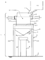
- the granulated powder cooling device 1 is composed of a support 2, a box 3, a cooling means 4, and a chute 5 as shown in FIG. (Including control panel).
- the support 2 supports the box 3 and the chute 5 and includes a rectangular support frame 21 and a plurality of support columns 22.
- the plurality of support columns 22 are arranged in a standing state on the floor F and support the support frame 21.
- the said box 3 accommodates the granulated powder 100 in the inside 31 temporarily.
- the box 3 has a square shape and is mounted on the support frame 21. Incidentally, the lower part of the box 3 is normally fixed to the support frame 21.
- the said cooling means 4 is forcedly cooled in the state which left the granulated powder 100 still.
- the stored powder leveling means 6 is provided on the upper part of the box 3 of the granulated powder cooling apparatus 1 according to the present invention.
- This accommodated powder leveling means 6 smoothes the granulated powder 100 accommodated in the interior 31 of the box 3 and makes the accumulated state of the granulated powder 100 uniform.
- the accommodated powder leveling means 6 of the present invention is not limited to the form shown in FIGS. 3 and 4.
- the discharge duct 11 of the mixer 10 is moved back and forth and / or left and right, or granulated.
- the rake for leveling the powder 100 is moved back and forth and / or left and right, the granulated powder can be secured in a uniform deposition state.
- the cooling means 4 in the granulated powder cooling device 1 according to the present invention forcibly cools the accommodated granulated powder 100 in a state where the granulated powder 100 is allowed to stand by the cooling body 41 disposed in the interior 31 of the box 3. Is. Therefore, according to the cooling means 4 of the present invention, it is possible to widen the cooling range of the granulated powder 100 in the box 3 without stirring the granulated powder 100, and the granulated particles are crushed. There is no fear of being done.
- the granulated powder cooling device 1 of the present invention uses such a chiller unit for the cooling means 4, compared with the conventional case where the box 3 itself is a cooling body, it has a simple configuration, The cooling range of the granulated powder 100 can be widened. Therefore, according to the granulated powder cooling apparatus 1 which concerns on this invention, the cooling time of the granulated powder 100 can be shortened rather than before, suppressing manufacturing cost.
- the cooling body cooling device 42 when the above-described configuration is adopted in the cooling means 4 of the present invention, the cooling body cooling device 42, the front water supply pipe 42b, the front branch water supply pipe 42a, and the cooling medium passage 41d of each cooling body 41 are provided.
- the cooling water can be circulated in the order of the rear branch water supply pipes 42 a, the rear water supply pipe 42 b, and the cooling body cooling device 42.
- water is used as the cooling medium used for the cooling means 4 of the present invention, but the present invention is not limited to this, and for example, nitrogen or the like can be used as appropriate.
- the cooling body 41 has an outer peripheral shape of a cross section perpendicular to the flow direction of the cooling medium having a polygonal shape such as a triangular shape or a quadrangular shape. preferable.
- the cooling body 41 of the present invention has a polygonal outer peripheral shape in a cross section perpendicular to the flow direction of the cooling medium (see FIGS. 5A to 5D).
- the cooling range of the granulated powder 100 can be widened without increasing the area occupied by the cooling body in the box 3 as compared with a cooling body having a circular outer peripheral shape in a cross section perpendicular to the flow direction.
- the cooling body 41 of this invention is a structure which consists of one, it arrange
- FIG. 6B when the cooling body 41 is arranged in a meandering manner and the folded portion is included in the box 3, the structure deposited in the vicinity of the folded portion. It is necessary to provide a gap between the folded portion and the box 3 to such an extent that the operation of dropping the particle powder 100 is possible.
- the cooling body 41 of this invention when arrange
- the cooling body 41 when the cooling body 41 is arranged in a state of standing in the box 3 in a substantially plate shape, at least one of the front surface or the back surface of the cooling body 41 is downward from above.
- the granulated powder 100 can easily slide on the front surface and / or the back surface of the cooling body 41. Therefore, by setting the cooling body 41 of the present invention to such a shape, accumulation of the granulated powder 100 on the cooling body 41 is suppressed, and the granulated powder 100 can be efficiently sent to the chute 5.
- vertical to the flow direction of the cooling medium of the said cooling body 41 is a mountain shape.
- the granulated powder cooling device 1 according to the present invention supplies the granulated powder 100 by forming at least the upper shape of the outer peripheral shape of the cross section perpendicular to the flow direction of the cooling medium of the cooling body 41 into a mountain shape. Occasionally, the granulated powder 100 falls while sliding on the upper slope of the cooling body 41, so that the bridging phenomenon hardly occurs in the box 3, and the granulated powder 100 can be efficiently accommodated in the box 3.
- FIG. 5A shows a form in which the upper portion 41a is formed in a mountain shape in the outer peripheral shape of the cross section perpendicular to the flow direction of the cooling medium of the cooling body 41 arranged in a standing state in the box 3. It is shown.
- FIG. 5 (a) when the cooling body 41 of the present invention has a substantially plate shape and is arranged in a standing state in the box 3, the surface 411 of the cooling body 41 is continuous vertically.
- the rear surface 412 of the cooling body 41 is also composed of two similar inclined surfaces 412a and 412b that are continuous in the vertical direction. It can be formed into a shape.
- the upper portion 41a in the outer peripheral shape of the cross section perpendicular to the flow direction of the cooling medium is not limited to the shape shown in FIG. 5A.
- FIG. The shape shown in FIG. 5 (g) can be obtained.
- FIGS. 5B and 5C in the outer peripheral shape of the cross section perpendicular to the flow direction of the cooling medium of the cooling body 41, only one side of the upper portion 41a is inclined (straight) from the upper side to the lower side. It is shown. 5 (e), FIG. 5 (f), and FIG. 5 (g), in the outer peripheral shape of the cross section perpendicular to the flow direction of the cooling medium of the cooling body 41, at least one side of the upper portion 41a is from top to bottom. An inclined (curved) form is shown.
- the cooling body 41 of the present invention it is more preferable that at least the lower shape of the outer peripheral shape of the cross section perpendicular to the flow direction of the cooling medium is an inverted mountain shape.
- the granulated powder cooling apparatus 1 according to the present invention has at least a lower part (a middle part 41b to a lower part 41c of the cooling body 41 in FIG. 5A) in the outer peripheral shape of the cross section perpendicular to the flow direction of the cooling medium of the cooling body 41.
- the granulated powder cooling device 1 employs the cooling body 41 having such a shape, so that when the granulated powder 100 is discharged, the contact between the granulated powder 100 and the cooling body 41 is reduced.
- the work efficiency accompanying the cooling treatment of the particle powder 100 can be further increased.
- the lower part (the part from the intermediate part 41b to the lower part 41c of the cooling body 41 in FIG. 5A) in the outer peripheral shape of the cross section perpendicular to the flow direction of the cooling medium is shown in FIG.
- the shape is not limited to the shape shown in FIG. 5A, and for example, the shape shown in FIGS. 5B to 5G can be used. 5 (b) to 5 (d) and FIG. 5 (f), in the outer peripheral shape of the cross section perpendicular to the flow direction of the cooling medium of the cooling body 41, the cooling in the lower part (FIG. 5 (a)).
- the outer peripheral shape of the cross section perpendicular to the flow direction of the cooling medium is not a polygonal shape, but has a substantially plate shape and the box 3
- the outer peripheral shape is arranged in an upright state and the lower portion of the outer peripheral shape is an inverted mountain shape, an effect substantially equivalent to the case where the outer peripheral shape is a polygonal shape can be exhibited.
- a plurality of cooling bodies 41 are provided in the box 3 and arranged at equal intervals along the left-right direction or the front-rear direction of the box 3. preferable.
- a plurality of cooling bodies 41 are provided in the box 3, so that the cooling medium 41 is provided in the box 3 of the cooling medium as compared with the case where a single cooling body 41 is provided in the box 3.
- the temperature difference between the vicinity of the inlet and the vicinity of the outlet can be reduced. Therefore, in the granulated powder cooling apparatus 1 according to the present invention, by providing a plurality of cooling bodies 41 in the box 3, the variation in the cooling rate of the granulated powder 100 in the box 3 is suppressed, and the box All the granulated powder 100 in 3 can be efficiently cooled. Therefore, the granulated powder cooling device 1 according to the present invention can reduce the cooling time and quality of the granulated powder 100 as the number of the cooling bodies 41 provided in the box 3 increases.
- the granulated powder cooling device 1 preferably further includes vibration devices 7 and 8 for vibrating the chute 5 and / or the box 3.
- the quality of the granulated particles constituting the granulated powder 100 is changed by hitting the box 3 before discharging the granulated powder 100 after cooling. It is more preferable to further include a vibration device 8 that crushes the granulated powder cake that has been pseudo-solidified by cooling without causing it to cool.
- the granulated powder cooling device 1 according to the present invention can further be provided with a vibration device 8 at an intermediate portion of the front wall 34 of the box 3 as shown in FIG.
- the vibration device 8 preferably employs a hammering method or the like and strikes the box 3 a predetermined number of times.
- the granulated powder cooling device 1 according to the present invention can pulverize the granulated powder cake by using the vibration device 8 without changing the quality of the granulated particles.
- the granulated powder cooling device 1 according to the present invention can collect the granulated powder 100 that has been cooled in a state before cooling, and suppress the quality degradation of the cooled granulated powder 100. I can do it.
- the granulated powder cake is a product in which the granulated powder 100 is pseudo-solidified by cooling.
- the vibration device 8 is preferably an air knocker or the like that performs an impacting operation such that when the granulated powder cake is crushed, the piston in the inside vigorously pops out and strikes the object. Can be used.
- the granulating apparatus A according to the present invention is a mixer for producing the granulated powder 100 by mixing the granulated powder cooling apparatus 1 of the present invention and two or more kinds of raw material powders while heating. It is equipped with.
- the granulating apparatus A is centrally managed by control means (including a control panel) (not shown) to control the discharge of the granulated powder 100 from the discharge duct 11, the front door 38a of the box 3, and It is possible to perform various controls such as opening / closing control of the rear door 38b, operation control of the cooling means 4, control of the stored powder leveling means 6, operation control of the vibration devices 7 and 8.
- the discharge duct 11 moves and supplies the formed granulated powder 100 to the inside 31 of the box 3.
- the bottom 38 of the box 3 is in a closed state. That is, the granulated powder 100 in a heated state is temporarily stored in the interior 31 of the box 3.
- the accommodated powder leveling means 6 is operated.
- the flattening rod 62 rotates horizontally within a range in the direction of arrow R in FIG. 4 for a predetermined time in a manner similar to that of the automobile wiper.
- the flattening rod 62 the granulated powder 100 is deposited in a uniform thickness.
- the cooling means 4 operates from the stage of storing the granulated powder 100 in the box 3.
- the cooling means 4 is configured such that the cooling water supplied from the cooling body cooling device 42 is supplied with a plurality of branch water supply pipes 42a and a plurality of cooling bodies via a water supply pipe 42b (only one water supply pipe is shown in FIG. 4). 41, it is made to circulate with the cooling body cooling device 42 through the water supply pipe 42b (the water supply pipe which illustration was omitted in FIG. 4).
- Each cooling body 41 is cooled by the circulation of the cooling water, and the granulated powder 100 in contact with the cooling body 41 is cooled.
- the granulated powder 100 is forcibly cooled in a state where the granulated powder in a heated state is allowed to stand, and this is a major feature of the granulated cooling apparatus 1 according to the present invention.
- the front door 38a and the rear door 38b of the bottom portion 38 of the box 3 are opened, and the granulated powder cake that has been solidified in a pseudo and gentle manner by cooling is obtained. Crush and drop without changing.
- the vibration device (knocker) 8 is operated to strike the side wall surface of the box 3 a predetermined number of times. Thereby, the said granulated powder cake is crushed and the fall of the granulated powder 100 adhering to the inner wall of the box 3 and the cooling body 41 is promoted.
- the granulated powder discharged from the bottom 38 of the box 3 passes through the chute 5 and falls onto the shifter (sieving) 91 of the shifter means B.
- a vibration device (vibrator) 7 is provided on the inner wall surface of the chute 5, and the granulated powder adhering to the inner wall surface of the chute 5 is efficiently dropped by applying vibration to the chute 5. Improve 100 collection efficiency.
- the shifter means B in which the shifter (sieving) 91 and the base 9 are integrated uses the shifter (sieving) 91 to swing it and drop the granulated powder 100.
- the granulated powder 100 that has been subjected to the sizing treatment falling from the shifter (sieving) 91 falls into the hopper 51 mounted on the moving carriage 50 and is stored as shown in FIG.
- the granulation apparatus A repeats the series of processes described above a predetermined number of times.
- the hopper 51 is transported to the molding machine together with the movable carriage 50, and the granulated powder 100 in the hopper 51 is used for mold molding.
- the granulating apparatus A enables the granulated powder cooling apparatus 1 to forcibly cool the granulated powder 100 in a heated state. That is, since the granulated powder cooling device 1 is cooling without moving the particles of the granulated powder 100, the granulated particles are destroyed, sheared, and generated in the cooling process of the conventional screw feeder type cooling device. Particle detachment is suppressed. Therefore, by using the granulating apparatus A according to the present invention, even if a cooling process is performed after heating and granulating, the mold fluidity provided by the granulated particles immediately after granulation is not greatly deteriorated, and the mold molding is performed. A granulated powder 100 having powder fluidity suitable for the above can be obtained.
- the granulated powder 100 was manufactured using the mixer 10, and this granulated powder 100 was cooled using the granulated powder cooling apparatus 1 according to the present invention.
- each powder of iron powder, hard powder (alloy powder), and lubricant was used as the raw material powder of the granulated powder 100 used in this example.
- the sampling amount which assumed the feeder cup was taken out from fixed quantity of the granulated powder 100 which cooling was complete
- This tester is capable of collecting a certain amount of granulated powder 100 and swinging it when the granulated powder with an appropriate particle size falls and measures the collected amount (g) It is.
- the amount of granulated powder with an appropriate particle size when the tester was swung 20 times was measured.
- the average value of the amount collected per oscillation was determined from the total amount of the collected granulated powder. This average value was 31.46 g.
- the granulated powder 100 obtained in the same manner as in the example was cooled using a screw feeder type granulated powder cooling device. And the collection amount of the granulated powder 100 was measured by the same method as an Example using the same testing machine as an Example. And the average value of the amount collected was calculated in the same manner as in the example. This average value was 28.42 g.
- the granulated powder cooling device according to the present invention described above and the granulating device including the granulated powder are cooled in a stationary state without moving the granulated particles in the cooling process of the granulated powder.
- the granulated particles can be cooled without changing the particle diameter that exhibits good powder flowability. Therefore, the granulated powder cooling apparatus and the granulating apparatus equipped with the granulated powder cooling apparatus according to the present invention are prepared by mixing two or more kinds of raw material powders and granulating them, and then adjusting the granulated particles in the powder metallurgy field using die molding. It can be suitably used for granulated particle adjustment of a raw material for producing a low-temperature fired ceramic material, granulated particle adjustment in the cemented carbide field and the like.
- a granulator B shifter means 1 granulated powder cooling device 3 box 4 cooling means 5 chute 5a discharge port 6 contained powder leveling means 7 vibration device 8 vibration device 10 mixer 11 discharge port 31 inside 32 supply port 38 bottom 41 Cooling body 41a Upper part 41c Lower part 41d Cooling medium passage 42 Cooling body cooling device 42a Branch water feeding pipe 42b Water feeding pipe 100 Granulated powder 411 Surface 411a Slope 411b Slope 412 Back face 412a Slope 412b Slope
Landscapes
- Physics & Mathematics (AREA)
- Thermal Sciences (AREA)
- Glanulating (AREA)
Applications Claiming Priority (2)
| Application Number | Priority Date | Filing Date | Title |
|---|---|---|---|
| JP2012-103968 | 2012-04-27 | ||
| JP2012103968 | 2012-04-27 |
Publications (1)
| Publication Number | Publication Date |
|---|---|
| WO2013162007A1 true WO2013162007A1 (fr) | 2013-10-31 |
Family
ID=49483303
Family Applications (1)
| Application Number | Title | Priority Date | Filing Date |
|---|---|---|---|
| PCT/JP2013/062422 Ceased WO2013162007A1 (fr) | 2012-04-27 | 2013-04-26 | Dispositif de refroidissement de poudre granulée et dispositif de granulation l'utilisant |
Country Status (1)
| Country | Link |
|---|---|
| WO (1) | WO2013162007A1 (fr) |
Cited By (6)
| Publication number | Priority date | Publication date | Assignee | Title |
|---|---|---|---|---|
| CN106422967A (zh) * | 2016-11-16 | 2017-02-22 | 陈业忠 | 一种易分散的珠状化妆品原料制造设备 |
| JP2017064752A (ja) * | 2015-09-30 | 2017-04-06 | 日立金属株式会社 | 粉末充填装置およびそれを用いた希土類焼結磁石の製造方法 |
| CN112536434A (zh) * | 2020-12-08 | 2021-03-23 | 江苏威拉里新材料科技有限公司 | 一种金属粉快速冷却收集设备以及收集工艺 |
| CN112675762A (zh) * | 2021-01-02 | 2021-04-20 | 周华梅 | 一种混合均匀的生物有机肥造粒机 |
| CN113390228A (zh) * | 2021-07-06 | 2021-09-14 | 陕西喜嘉彩新型材料有限公司 | 一种粉末涂料冷却控制系统 |
| CN113385674A (zh) * | 2021-06-09 | 2021-09-14 | 河源正信硬质合金有限公司 | 一种能将金属粉末融合到硬质合金的高温成型装置 |
Citations (6)
| Publication number | Priority date | Publication date | Assignee | Title |
|---|---|---|---|---|
| JPS4989171U (fr) * | 1972-10-05 | 1974-08-02 | ||
| JPS5227095A (en) * | 1975-08-28 | 1977-03-01 | Ishikawajima Harima Heavy Ind Co Ltd | Method and apparatus for heat recovery of molten slag |
| JPS59159000U (ja) * | 1983-04-09 | 1984-10-25 | 石川島播磨重工業株式会社 | 粉粒体顕熱回収装置 |
| JPS6457071A (en) * | 1987-06-05 | 1989-03-03 | Heeren Tefuniiku Bv | Device for cooling and/or drying bulk cargo |
| JPH1163870A (ja) * | 1997-08-25 | 1999-03-05 | Kawasaki Heavy Ind Ltd | 排熱回収装置 |
| JP2003231901A (ja) * | 2002-02-13 | 2003-08-19 | Sugiyama Juko Kk | 機械的合金製造方法及びその装置 |
-
2013
- 2013-04-26 WO PCT/JP2013/062422 patent/WO2013162007A1/fr not_active Ceased
Patent Citations (6)
| Publication number | Priority date | Publication date | Assignee | Title |
|---|---|---|---|---|
| JPS4989171U (fr) * | 1972-10-05 | 1974-08-02 | ||
| JPS5227095A (en) * | 1975-08-28 | 1977-03-01 | Ishikawajima Harima Heavy Ind Co Ltd | Method and apparatus for heat recovery of molten slag |
| JPS59159000U (ja) * | 1983-04-09 | 1984-10-25 | 石川島播磨重工業株式会社 | 粉粒体顕熱回収装置 |
| JPS6457071A (en) * | 1987-06-05 | 1989-03-03 | Heeren Tefuniiku Bv | Device for cooling and/or drying bulk cargo |
| JPH1163870A (ja) * | 1997-08-25 | 1999-03-05 | Kawasaki Heavy Ind Ltd | 排熱回収装置 |
| JP2003231901A (ja) * | 2002-02-13 | 2003-08-19 | Sugiyama Juko Kk | 機械的合金製造方法及びその装置 |
Cited By (7)
| Publication number | Priority date | Publication date | Assignee | Title |
|---|---|---|---|---|
| JP2017064752A (ja) * | 2015-09-30 | 2017-04-06 | 日立金属株式会社 | 粉末充填装置およびそれを用いた希土類焼結磁石の製造方法 |
| CN106422967A (zh) * | 2016-11-16 | 2017-02-22 | 陈业忠 | 一种易分散的珠状化妆品原料制造设备 |
| CN106422967B (zh) * | 2016-11-16 | 2024-04-16 | 陈业忠 | 一种易分散的珠状化妆品原料制造设备 |
| CN112536434A (zh) * | 2020-12-08 | 2021-03-23 | 江苏威拉里新材料科技有限公司 | 一种金属粉快速冷却收集设备以及收集工艺 |
| CN112675762A (zh) * | 2021-01-02 | 2021-04-20 | 周华梅 | 一种混合均匀的生物有机肥造粒机 |
| CN113385674A (zh) * | 2021-06-09 | 2021-09-14 | 河源正信硬质合金有限公司 | 一种能将金属粉末融合到硬质合金的高温成型装置 |
| CN113390228A (zh) * | 2021-07-06 | 2021-09-14 | 陕西喜嘉彩新型材料有限公司 | 一种粉末涂料冷却控制系统 |
Similar Documents
| Publication | Publication Date | Title |
|---|---|---|
| WO2013162007A1 (fr) | Dispositif de refroidissement de poudre granulée et dispositif de granulation l'utilisant | |
| CN110947447A (zh) | 一种粉末涂料极细研磨装置 | |
| CA3110511C (fr) | Procede de fusion de minerai d'oxyde | |
| CN111230040B (zh) | 一种消失模铸造后砂土循环再利用装置 | |
| US20210229132A1 (en) | Systems and methods for winnowing food products | |
| CN114273224B (zh) | 一种湿软粘性颗粒物料分拣设备 | |
| KR20150118442A (ko) | 과립장치 | |
| CN116984096A (zh) | 一种水性涂料制备原料加工工艺 | |
| CN112916178B (zh) | 一种机制砂的制砂设备 | |
| JP6477711B2 (ja) | 鋳物砂処理設備 | |
| CN107343543A (zh) | 一种茶叶生产用烘干筛选装置 | |
| CN115921062A (zh) | 新材料破碎装置 | |
| CN208523678U (zh) | 一种坚果巧克力加工系统 | |
| CN119368062A (zh) | 一种金属陶瓷刀具制备装置及其制备方法 | |
| KR20140136127A (ko) | 환약성형기 | |
| EP4305003B1 (fr) | Procédé et installation de préparation d'un granulé à usage céramique | |
| CN208679025U (zh) | 用于岩矿壶制备的原料混料装置 | |
| CN116475403A (zh) | 一种粉末冶金用铁粉制备装置及方法 | |
| CN210552268U (zh) | 一种混料装置 | |
| CN201040248Y (zh) | 自由落体自动粉碎机 | |
| CN115284494A (zh) | 一种全自动冷藏式打料装置 | |
| JP5994558B2 (ja) | コンクリート用粗骨材の製造方法及び装置 | |
| CN210787664U (zh) | 一种串联式研磨装置 | |
| RU2643046C1 (ru) | Устройство для гранулирования | |
| CN217164570U (zh) | 一种覆膜砂生产高效破碎装置 |
Legal Events
| Date | Code | Title | Description |
|---|---|---|---|
| 121 | Ep: the epo has been informed by wipo that ep was designated in this application |
Ref document number: 13781731 Country of ref document: EP Kind code of ref document: A1 |
|
| NENP | Non-entry into the national phase |
Ref country code: DE |
|
| 122 | Ep: pct application non-entry in european phase |
Ref document number: 13781731 Country of ref document: EP Kind code of ref document: A1 |
|
| NENP | Non-entry into the national phase |
Ref country code: JP |