WO2013164888A1 - Boucle à déblocage avant - Google Patents
Boucle à déblocage avant Download PDFInfo
- Publication number
- WO2013164888A1 WO2013164888A1 PCT/JP2012/061588 JP2012061588W WO2013164888A1 WO 2013164888 A1 WO2013164888 A1 WO 2013164888A1 JP 2012061588 W JP2012061588 W JP 2012061588W WO 2013164888 A1 WO2013164888 A1 WO 2013164888A1
- Authority
- WO
- WIPO (PCT)
- Prior art keywords
- cover body
- socket
- plug
- main body
- tongue
- Prior art date
- Legal status (The legal status is an assumption and is not a legal conclusion. Google has not performed a legal analysis and makes no representation as to the accuracy of the status listed.)
- Ceased
Links
Images


Classifications
-
- A—HUMAN NECESSITIES
- A44—HABERDASHERY; JEWELLERY
- A44B—BUTTONS, PINS, BUCKLES, SLIDE FASTENERS, OR THE LIKE
- A44B11/00—Buckles; Similar fasteners for interconnecting straps or the like, e.g. for safety belts
- A44B11/25—Buckles; Similar fasteners for interconnecting straps or the like, e.g. for safety belts with two or more separable parts
- A44B11/2503—Safety buckles
- A44B11/2507—Safety buckles actuated by a push-button
- A44B11/2511—Safety buckles actuated by a push-button acting perpendicularly to the main plane of the buckle, e.g. placed on the front face of the buckle
Definitions
- the present invention relates to a front release buckle that is disengaged by operating a front portion.
- a buckle for detachably engaging a plug and a socket has been used in order to connect string-like members such as a belt for various uses such as clothes, bags, shoes, and packaging.
- string-like members such as a belt
- a front release buckle with a lock mechanism that is disengaged by operating a front portion is used.
- the socket is provided with a lock plate that can slide on the elastic pressing piece.
- the lock plate is provided so that the tongue-like portion is not inadvertently pressed, and the displacement of the elastic pressing piece during the rotation is not changed until the lock plate is slid. And the tongue portion can be pressed.
- the socket includes a main body and a cover body pivotally supported by the main body.
- a tongue-like portion standing toward the attachment side of the cover body is provided so as to be elastically deformable.
- An engaged portion that engages with an engaging portion of the plug is provided on one end side of the cover body, and a shaft portion that is pivotally supported with respect to the main body is formed at the center of the cover body. The end side is in contact with the tip of the tongue.
- the cover body is rotatably attached to the main body with the shaft portion as a rotation center, and in the attached state, the tongue-like portion urges the other end side of the cover body from the back surface side. For this reason, in order to release the engagement between the plug and the socket, it is only necessary to press the other end of the cover body against the urging force of the tongue-like portion, and the cover body can be rotated by doing so. Then, one end side of the cover body is lifted, and the engaging portion of the plug is detached from the engaged portion of the cover body.
- the engaged portion is provided on the cover body, when the plug and the socket are engaged, when the belt is pulled in the pulling-out direction of the plug, the tension is passed through the mutual engaging portion. May act on the shaft portion, and the shaft portion may be damaged and the cover body may come off.
- an object of the present invention is to provide a front release buckle that can facilitate the operation of the cover body when releasing the engagement between the plug and the socket and can reliably prevent the shaft portion of the cover body from being damaged. It was decided.
- the front release buckle of the present invention includes a plug, a socket into which the plug is inserted and engaged, and a cover body that is pivotally supported by the socket.
- the plug includes a base portion and the base portion.
- An engaging portion formed in the engaging piece, and the socket is formed in the main body and inserted from the inserting port.
- a tongue-like portion that is formed integrally with the main body and can be elastically deformed. The engagement portion engages with the tongue-like portion.
- a possible engaged portion is formed, and the cover body is formed with a shaft portion pivotally supported with respect to the socket on one end side in the plug insertion direction of the cover body, and the plug insertion direction of the cover body
- a pressing projection having a pressing portion for elastically deforming the tongue-like portion is formed on the other end side It is characterized in that is.
- the cover body since the shaft portion and the pressing portion corresponding to the pressing protrusion are largely separated from one end side and the other end side, a wide area excluding the one end side where the cover body is pivotally supported is formed. It can be easily pressed and can be reliably rotated. Further, the cover body has a function of rotating around the shaft portion and elastically deforming the tongue-like portion by this rotation, and the tongue-like portion has a function of engaging with the plug. That's fine. Therefore, the cover body does not need to have both the rotation function and the engagement function, and even if the plug is pulled through the belt, the tension does not act on the shaft portion of the cover body, and the shaft portion is damaged. Can prevent the cover body from falling off.
- the pressing protrusion is formed with a restricting portion for restricting the rotation of the cover body extending in a direction intersecting the extending direction of the pressing portion, and the main body has a thickness direction of the socket. It is desirable that a pair of wall portions that form the insertion port are formed opposite to each other, and the restricting portion is located between the pair of wall portions.
- the pressing protrusion is formed with a restricting portion extending in a direction intersecting the extending direction of the pressing portion, and the restricting portion is located between the pair of wall portions, so that the cover body is rotated. In this case, the amount of rotation of the cover body can be restricted by the restriction portion coming into contact with one of the wall portions, and the cover body can be prevented from being detached from the socket.
- an opening is formed in the center of the main body, and the tongue-like portion is provided in the opening.
- the tongue-like portion is provided in the opening of the main body, the thickness dimension of the socket can be reduced and the thickness can be reduced.
- a finger hook portion is formed integrally with the main body in the same plane as the tongue-like portion so as to be separated from the tongue-like portion.
- the finger hook portion is formed separately from the tongue portion, when the finger is put on the finger hook portion, the finger does not reach the tongue portion, and the cover body When the is pressed, only the tongue-like portion can be reliably elastically deformed, and the engagement between the plug and the socket can be reliably released.
- an auxiliary guide groove for assisting the guide of the engaging portion to the engaged portion is provided at a position surrounding the engaging portion of the engaging piece at a predetermined depth in the thickness direction of the engaging piece.
- the auxiliary guide protrusion for assisting the guide of the engaging portion to the engaged portion is directed to the accommodating space at a position corresponding to the auxiliary guide groove of the tongue-shaped portion. It is desirable that it is formed with a predetermined protruding height.
- the main body of the socket is provided with a guide groove for guiding the engaging piece into the main body along the insertion direction of the plug, and the guide groove is inserted in the insertion direction of the plug.
- the front end side also serves as a bearing groove into which the shaft portion of the cover body is fitted, and the main body is locked with the cover body to restrict movement of the cover body along the guide groove.
- a locking portion is provided.
- the main body is provided with a locking portion, and the locking portion is locked to the cover body. Therefore, even if the cover body is positioned in a state where the shaft portion is fitted in the guide groove also serving as the bearing portion. The movement of the cover body along the guide groove can be restricted, and the cover body can be prevented from being detached from the socket.
- FIG. 1 is a perspective view showing an entire configuration according to an embodiment of the present invention from the front side.
- the front release buckle 1 of the present embodiment includes a plug 10, a socket 20 into which the plug 10 is inserted and engaged, and a cover body 30 that is pivotally supported by the socket 20. It has.
- the front release buckle 1 of this embodiment is for connecting / separating ends of a string-like member such as a belt, and the plug 10, the socket 20 and the cover body 30 are each formed by injection molding of a synthetic resin.
- the material of the plug 10, the socket 20 and the cover body 30 is not limited to synthetic resin but may be other materials such as metal, and is not limited to injection molding, but by other molding methods such as casting or cutting. Also good.
- FIG. 2 is a perspective view showing the plug of the embodiment from the front side.
- FIG. 3 is a perspective view showing the plug of the embodiment from the back side. 2 and 3, the plug 10 is integrally formed as a whole, and a base 11 to be gripped by a user, a pair of engaging pieces 12 inserted into a socket 20, a belt and the like are inserted. A belt mounting portion 13.
- the engagement pieces 12 protrude in the length direction (the insertion direction of the plug 10 with respect to the socket 20, the vertical direction in FIGS. 1 to 3) from the base 11 and are parallel to each other, and the width of the base 11 (
- the plug 10 is inserted in parallel with a predetermined interval W1 in the insertion direction of the plug 10 with respect to the socket 20 and the direction orthogonal to the thickness direction of the socket 20 (left and right direction in FIGS. 1 to 3).
- the predetermined interval W1 is formed slightly larger than the width W2 of the pressing protrusion 32 (described later). As shown in FIG.
- each engagement piece 12 is formed with an auxiliary guide groove 12 ⁇ / b> A having a predetermined depth in the thickness direction of the engagement piece 12 so as to surround the engagement portion 101 (described later). .
- the auxiliary guide groove 12 ⁇ / b> A assists the guide of the engaging portion 101 to the engaged portion 201 (described later) when the plug 10 is inserted into the socket 20.
- Each of the engagement pieces 12 is formed with a protruding protrusion 101.
- the engaging portion 101 includes an inclined base portion 101A, a flat surface portion 101B continuous from the inclined base portion 101A in the length direction of the engaging piece 12 (up and down direction in FIG. 3), and an engagement inclined at a predetermined angle with respect to the flat surface portion 101B. 101C (see FIGS. 7 to 10).
- the engaging portion 101 is guided by an auxiliary guide protrusion 202 (described later) formed inside the socket 20 together with the auxiliary guide groove 12A, and the plug 10 is guided to an appropriate position during insertion operation. It has come to be.
- the belt mounting portion 13 has a belt attachment hole 13A into which an end portion of the belt is inserted at the center of the inside, and is located in a width direction at a position that is an end portion of the plug 10 and an end portion of the base portion 11.
- a first bar 13B extending to the belt is installed, and a second bar 13C is installed in the middle of the belt mounting hole 13A.
- the belt mounting hole 13A is inserted into the insertion direction front end side 13D and the insertion direction rear end side by the second bar 13C. 13E and divided into two.
- a belt (not shown) is inserted from the back side (the back side of the paper in FIG. 2) of the plug 10 toward the front side (the front side of the paper in FIG. 2) to the front end side 13D in the insertion direction. From the front side to the back side, it is inserted into the rear end side 13E in the insertion direction and comes to the back side of the first bar 13B. Then, the front end side of the belt is sandwiched between the first bar 13B and the base end side of the belt.
- the belt can be engaged and fixed, and the length can be adjusted.
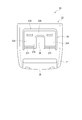
- FIG. 4 is a perspective view showing the socket of the embodiment from the front side.
- FIG. 5 is a rear view showing the socket of the embodiment. 1, 4, and 5, the socket 20 is integrally formed as a whole.
- the socket 20 has a hollow main body 21 having an insertion port 22, and is formed in the main body 21 from the insertion port 22.
- An accommodation space 24 (see FIGS. 7 to 10) capable of accommodating the engagement piece 12 of the plug 10 inserted therein and an opening 21D of the main body 21 so as to be elastically deformable with respect to the main body 21 are provided.
- a tongue portion 25, a finger hook portion 26 provided in the same plane as the tongue portion 25 at the center of the socket 20, and a belt mounting portion 28 into which a belt (not shown) is inserted and locked.
- the main body 21 is opposed to the thickness direction of the socket 20 and has a bar-shaped upper wall portion 21A and a lower wall portion 21B (see FIGS. 7 to 10).
- the lower wall portion 21B is adjacent to the tongue portion 25 in the length direction of the socket 20 (vertical direction in FIG. 4), and the surface facing the insertion port 22 of the lower wall portion 21B is the insertion of the plug 10.
- the inclined surface 21B1 (see FIGS. 7 to 10) approaches the upper wall portion 21A as it goes in the direction.
- a pair of guide recesses 21 ⁇ / b> C that are opposed to each other in the width direction of the socket 20 and guide a shaft portion 31 (described later) of the cover body 30 are formed on the inner periphery of the main body 21.
- An opening 21 ⁇ / b> D is formed at the center of the main body 21.
- a pair of guide grooves 23 for guiding the engagement pieces 12 of the plug 10 along the insertion direction (vertical direction in FIG. 4) of the plug 10 are provided inside both sides of the main body 21 in the width direction (left and right direction in FIG. 4). Is formed.
- the guide groove 23 reaches a position corresponding to the guide recess 21C on the distal end side in the insertion direction of the plug 10, and the extension portion of the guide recess 21C in the guide groove 23 fits the shaft portion 31 of the cover body 30.
- the bearing groove 231 is also used.
- a pair of locking portions 27 projecting in the thickness direction of the socket 20 are provided at positions on the belt mounting portion 28 side of the main body 21.
- the locking portion 27 is a substantially quadrangular shape with rounded corners in plan view, protrudes in the thickness direction of the socket 20, and is provided to lock with a step portion 30 ⁇ / b> A (described later) of the cover body 30.
- the tongue 25 is provided in the opening 21 ⁇ / b> D of the main body 21 so as to be elastically deformable in a cantilever state in the thickness direction of the socket 20.
- the tongue 25 has a pair of engaged pieces 25A that extend in the length direction of the main body 21 (vertical direction in FIG. 4) and are parallel to each other, and a connecting portion 25B that connects the engaged pieces 25A. .
- the base end portion 251 of the engaged piece 25 ⁇ / b> A is thin, and the engaged piece 25 ⁇ / b> A is easily elastically deformed with respect to the main body 21.
- An engaged portion 201 that can engage with the engaging portion 101 of the plug 10 is formed on the engaged piece 25A.
- the engaged portions 201 protrude from the engaged pieces 25A toward the accommodation space 24 and have a predetermined protruding height.
- the protruding heights of these engaged portions 201 correspond to the engaging portions 101 of the plug 10.
- An engaged surface 201 ⁇ / b> A is formed on the engaged portion 201, and the engaging portion 101 engages with the engaged portion 201 on the engaged surface 201 ⁇ / b> A.
- auxiliary guide protrusions 202 extending in parallel along the insertion direction of the plug 10 are provided on both sides of the engaged portion 201.
- the auxiliary guide protrusion 202 protrudes toward the accommodation space 24 in the same manner as the engaged part 201, and the engaged part 201 and the auxiliary guide protrusion 202 are continuously formed in a substantially H shape.
- the auxiliary guide protrusion 202 guides the engaging portion 101 to the engaged portion 201 corresponding to the auxiliary guide groove 12A on the plug 10 side when the engaging piece 12 of the plug 10 is inserted from the insertion port 22. To help.
- the finger rest 26 is formed separately from the tongue 25 in the opening 21 ⁇ / b> D, and the finger does not reach the tongue 25 when the finger rests on the finger rest 26. It is configured as follows.
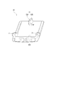
- FIG. 6 is a perspective view showing the cover body of the embodiment from the back side.
- the cover body 30 has a rectangular shape as a whole, and has a pair of shaft portions 31 formed to protrude toward both sides in the width direction on one end portion side, and on the opposite side of the shaft portion 31. It has a pressing projection 32 formed to project toward the tongue 25 on the other end side.
- the pressing protrusion 32 abuts on the connecting portion 25B of the tongue-like portion 25 and elastically deforms the tongue-like portion 25, and the extending direction of the pressing portion 32A intersects.
- a restricting portion 32B extending in the direction.
- Such a cover body 30 is pivotally supported by the socket 20 by the shaft portion 31 being guided by the guide recess 21 ⁇ / b> C formed in the main body 21 and fitted in the bearing groove 231. At this time, the front end of the locking portion 27 of the main body 21 is locked to the step portion 30 ⁇ / b> A of the cover body 30, thereby restricting the movement of the cover body 30 along the guide groove 23.
- the cover body 30 rotates so as to sink in the thickness direction of the socket 20 with the shaft portion 31 as the rotation center.
- the restricting portion 32B is located between the upper wall portion 21A and the lower wall portion 21B, and when the cover body 30 is rotated, The amount of rotation of the cover body 30 is regulated by contacting the upper wall portion 21A and the lower wall portion 21B. Specifically, when the pressing protrusion 32 side of the cover body 30 is pressed, the restricting portion 32B comes into contact with the inclined surface 21B1 of the lower wall portion 21B.
- the restricting portion 32B is It contacts the part 21A.
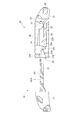
- FIG. 7 is a cross-sectional view showing a connected state of the plug and socket of the embodiment.
- FIG. 8 is a cross-sectional view showing a state when the cover body of the embodiment is pressed.
- FIG. 9 is a cross-sectional view showing a state where the engagement between the plug and the socket of the embodiment is released.
- FIG. 10 is a cross-sectional view illustrating a state in which the engagement between the plug and the socket of the embodiment is released and the cover body is returned to the original position.
- the shaft portion 31 of the cover body 30 and the pressing portion corresponding to the pressing protrusion 32 are greatly separated from one end side and the other end side.
- the cover body 30 can be pressed by an operation on a wide area excluding one end side, and the cover body 30 can be easily and reliably rotated.
- the rotation function by the user's operation and the engagement function with respect to the plug 10 are completely separated into the cover body 30 and the tongue 25, the rotation function and the engagement function are provided on the cover body 30. Unlike the conventional case in which both are provided, even if the plug 10 is pulled through the belt, the tension can be prevented from acting on the shaft portion 31 of the cover body 30, and the cover body 30 due to the breakage of the shaft portion 31 can be prevented. Can be prevented from falling off.
- the pressing protrusion 32 of the cover body 30 is formed with a restricting portion 32B extending in a direction crossing the extending direction of the pressing portion 32A, and the restricting portion 32B is interposed between the upper wall portion 21A and the lower wall portion 21B.
- the restricting portion 32B comes into contact with the lower wall portion 21B and the amount of rotation of the cover body 30 can be restricted.
- the restricting portion 32B moves to the upper wall portion 21A.
- the amount of rotation of the cover body 30 can be regulated by contact. This can prevent the cover body 30 from being detached from the socket 20.
- an opening 21 ⁇ / b> D is formed in the center of the main body 21, and the tongue 25 is provided in the opening 21 ⁇ / b> D. Therefore, the thickness of the socket 20 can be reduced, and the socket 20 can be made thinner.
- the finger rest 26 is formed separately from the tongue 25, so that when the finger is put on the finger rest 26, the finger does not reach the tongue 25, and the cover body When the 30 is pressed, only the tongue 25 can be reliably elastically deformed, and the engagement between the plug 10 and the socket 20 can be reliably released.
- the engagement portion 101 is formed by the auxiliary guide groove 12A and the auxiliary guide protrusion 202. To the engaged portion 201 can be assisted without rattling. Thereby, the engaging part 101 can be smoothly engaged with the engaged part 201.
- the auxiliary guide protrusion 202 is continuously formed extending from both sides of the engaged portion 201 in a direction orthogonal to the extending direction of the engaged portion 201, and therefore, the auxiliary guide protrusion 202 is covered by the auxiliary guide protrusion 202.
- the engaging part 201 can be reinforced.
- the cover body 30 moves along the guide groove 23 even if the cover body 30 is pivotally supported in the guide groove 23.
- the cover body 30 can be prevented from being detached from the socket 20.
- the locking portion 27 in combination the cover 30 can be pivotally supported in the guide groove 23, and the guide groove 23 is opened to the insertion port 22 side of the socket 20.
- a complicated mold as in the case of forming a hole shape into which the shaft portion 31 is fitted on the inner surface is not necessary, and the design of the mold can be facilitated and the cost can be reduced.
- the present invention is not limited to the structure of the above embodiment, but includes the following modifications.
- the pair of engaging portions 101 and the pair of engaged portions 201 are not limited to a pair, and one engaging portion 101 is provided in a single engaging piece 12, A configuration in which one joining portion 201 is also provided may be used.
- the cover body 30 may be provided with a pair of pressing protrusions 32 so as to press both sides of the engaged portion 201 in the width direction.
- each of the engaging portion 101, the engaged portion 201, and the pressing protrusion 32 may be provided in an appropriate number for the implementation, and may be three or more.
- the tongue-like portion 25 is connected to the connecting portion. 25B may not be included.
- the finger hook portion 26 may extend to the insertion port 22 of the main body 21.
- the engaging portion 27 protrudes from the socket 20 and is not limited to a configuration in which the engaging portion 27 protrudes from the cover body 30 and contacts the stepped portion formed in the socket 20. You may let them.
- the present invention is a buckle that connects belts, and can be used as a front release buckle that performs a release operation on the front side of the buckle.
Landscapes
- Buckles (AREA)
Priority Applications (2)
| Application Number | Priority Date | Filing Date | Title |
|---|---|---|---|
| PCT/JP2012/061588 WO2013164888A1 (fr) | 2012-05-02 | 2012-05-02 | Boucle à déblocage avant |
| TW102115268A TW201404328A (zh) | 2012-05-02 | 2013-04-29 | 前釋式帶扣 |
Applications Claiming Priority (1)
| Application Number | Priority Date | Filing Date | Title |
|---|---|---|---|
| PCT/JP2012/061588 WO2013164888A1 (fr) | 2012-05-02 | 2012-05-02 | Boucle à déblocage avant |
Publications (1)
| Publication Number | Publication Date |
|---|---|
| WO2013164888A1 true WO2013164888A1 (fr) | 2013-11-07 |
Family
ID=49514298
Family Applications (1)
| Application Number | Title | Priority Date | Filing Date |
|---|---|---|---|
| PCT/JP2012/061588 Ceased WO2013164888A1 (fr) | 2012-05-02 | 2012-05-02 | Boucle à déblocage avant |
Country Status (2)
| Country | Link |
|---|---|
| TW (1) | TW201404328A (fr) |
| WO (1) | WO2013164888A1 (fr) |
Cited By (1)
| Publication number | Priority date | Publication date | Assignee | Title |
|---|---|---|---|---|
| DE112021007645T5 (de) | 2021-05-10 | 2024-02-15 | Ykk Corporation | Stecker und Schnalle |
Families Citing this family (2)
| Publication number | Priority date | Publication date | Assignee | Title |
|---|---|---|---|---|
| US9980539B2 (en) * | 2014-08-11 | 2018-05-29 | Apple Inc. | Segmented attachment device |
| DE102024105180B3 (de) * | 2024-02-23 | 2025-08-14 | Mewa Textil-Service Se & Co. Management Ohg | Steckschließe |
Citations (5)
| Publication number | Priority date | Publication date | Assignee | Title |
|---|---|---|---|---|
| JPS6454805U (fr) * | 1987-09-30 | 1989-04-04 | ||
| JPH0746167Y2 (ja) * | 1989-11-10 | 1995-10-25 | ワイケイケイ株式会社 | バックル |
| JP2000157309A (ja) * | 1998-11-30 | 2000-06-13 | Ykk Corp | バックル |
| JP2000197507A (ja) * | 1997-12-29 | 2000-07-18 | Natl Molding Corp | バックル・アセンブリ |
| JP2007105455A (ja) * | 2005-10-12 | 2007-04-26 | Paik Nam-Il | バックル |
-
2012
- 2012-05-02 WO PCT/JP2012/061588 patent/WO2013164888A1/fr not_active Ceased
-
2013
- 2013-04-29 TW TW102115268A patent/TW201404328A/zh unknown
Patent Citations (5)
| Publication number | Priority date | Publication date | Assignee | Title |
|---|---|---|---|---|
| JPS6454805U (fr) * | 1987-09-30 | 1989-04-04 | ||
| JPH0746167Y2 (ja) * | 1989-11-10 | 1995-10-25 | ワイケイケイ株式会社 | バックル |
| JP2000197507A (ja) * | 1997-12-29 | 2000-07-18 | Natl Molding Corp | バックル・アセンブリ |
| JP2000157309A (ja) * | 1998-11-30 | 2000-06-13 | Ykk Corp | バックル |
| JP2007105455A (ja) * | 2005-10-12 | 2007-04-26 | Paik Nam-Il | バックル |
Cited By (1)
| Publication number | Priority date | Publication date | Assignee | Title |
|---|---|---|---|---|
| DE112021007645T5 (de) | 2021-05-10 | 2024-02-15 | Ykk Corporation | Stecker und Schnalle |
Also Published As
| Publication number | Publication date |
|---|---|
| TW201404328A (zh) | 2014-02-01 |
Similar Documents
| Publication | Publication Date | Title |
|---|---|---|
| CN103251178B (zh) | 旁开扣 | |
| TWI263478B (en) | Buckle | |
| EP2641498B1 (fr) | Boucle | |
| JP5544019B2 (ja) | カムロックバックル | |
| CN102711545B (zh) | 旁开扣及其锁定构件 | |
| JP4008472B2 (ja) | 折り畳みコンテナ | |
| CN104125786B (zh) | 带扣 | |
| US20080178438A1 (en) | Buckle | |
| JP5260199B2 (ja) | コンパクト容器 | |
| CN101436734A (zh) | 装有锁定器的连接器 | |
| JP4528642B2 (ja) | バックル | |
| JP5552534B2 (ja) | フロントリリースバックル | |
| CN108712869A (zh) | 卡扣 | |
| WO2013164888A1 (fr) | Boucle à déblocage avant | |
| KR101343759B1 (ko) | 버클 | |
| JP6462510B2 (ja) | バックル | |
| TWI557343B (zh) | With body adjustment | |
| JP7369598B2 (ja) | 保護カバー | |
| JP2005231723A (ja) | 組立式合成樹脂製容器 | |
| JP7407564B2 (ja) | 保護カバー、及び、連結機構 | |
| TWI486132B (zh) | Buckle (a) | |
| JP5241390B2 (ja) | コンパクト容器 | |
| CN101285496A (zh) | 弹性钩 | |
| JP4399377B2 (ja) | バックル | |
| CN106606010A (zh) | 带扣 |
Legal Events
| Date | Code | Title | Description |
|---|---|---|---|
| 121 | Ep: the epo has been informed by wipo that ep was designated in this application |
Ref document number: 12875816 Country of ref document: EP Kind code of ref document: A1 |
|
| NENP | Non-entry into the national phase |
Ref country code: DE |
|
| 122 | Ep: pct application non-entry in european phase |
Ref document number: 12875816 Country of ref document: EP Kind code of ref document: A1 |
|
| NENP | Non-entry into the national phase |
Ref country code: JP |