WO2013165015A1 - Dispositif relais de réseau et programme - Google Patents
Dispositif relais de réseau et programme Download PDFInfo
- Publication number
- WO2013165015A1 WO2013165015A1 PCT/JP2013/062714 JP2013062714W WO2013165015A1 WO 2013165015 A1 WO2013165015 A1 WO 2013165015A1 JP 2013062714 W JP2013062714 W JP 2013062714W WO 2013165015 A1 WO2013165015 A1 WO 2013165015A1
- Authority
- WO
- WIPO (PCT)
- Prior art keywords
- data
- unit
- switch
- information
- identification information
- Prior art date
- Legal status (The legal status is an assumption and is not a legal conclusion. Google has not performed a legal analysis and makes no representation as to the accuracy of the status listed.)
- Ceased
Links
Images




Classifications
-
- H—ELECTRICITY
- H04—ELECTRIC COMMUNICATION TECHNIQUE
- H04L—TRANSMISSION OF DIGITAL INFORMATION, e.g. TELEGRAPHIC COMMUNICATION
- H04L49/00—Packet switching elements
- H04L49/25—Routing or path finding in a switch fabric
-
- H—ELECTRICITY
- H04—ELECTRIC COMMUNICATION TECHNIQUE
- H04L—TRANSMISSION OF DIGITAL INFORMATION, e.g. TELEGRAPHIC COMMUNICATION
- H04L49/00—Packet switching elements
- H04L49/15—Interconnection of switching modules
-
- H—ELECTRICITY
- H04—ELECTRIC COMMUNICATION TECHNIQUE
- H04L—TRANSMISSION OF DIGITAL INFORMATION, e.g. TELEGRAPHIC COMMUNICATION
- H04L9/00—Cryptographic mechanisms or cryptographic arrangements for secret or secure communications; Network security protocols
- H04L9/32—Cryptographic mechanisms or cryptographic arrangements for secret or secure communications; Network security protocols including means for verifying the identity or authority of a user of the system or for message authentication, e.g. authorization, entity authentication, data integrity or data verification, non-repudiation, key authentication or verification of credentials
Definitions
- the present invention relates to a network relay device such as a network switch and a program thereof.
- Non-Patent Document 1 An open flow network, etc.
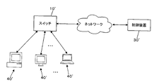
- Fig. 11 shows an overview of this OpenFlow network.
- the network shown in this example includes a switch 10 ', a control device 30', and a plurality of terminal devices 40 '.
- the switch 10 ' has a plurality of network ports, and each terminal device 40' is connected to one of the network ports of the switch 10 '.
- the switch 10 'and the control device 30' are connected to each other via a network (such as the Internet) so that they can communicate with each other.
- a network such as the Internet
- the terminal device 40 ' When the terminal device 40 'is activated, the terminal device 40' starts data transmission to the switch 10 '. This data is divided into units called frames, and the switch 10 'transmits the first frame (the first frame received from the terminal device 40') to the control device 30 '.
- the communication between the switch 10 'and the control device 30' is encrypted by SSL or the like.
- the control device 30 ′ determines whether or not a new process is necessary in accordance with the communication of the terminal device 40 ′ that has transmitted the frame according to a predetermined criterion. to decide.
- information that defines the content of the required process is transmitted to the switch 10 'according to the determination.
- the switch 10 'receives and stores this information, and thereafter executes a process defined by this information.
- the content of processing specified by this information includes rules and actions.
- the rule is information indicating what the target is, and the action indicates the specific content of the processing related to the target.
- the switch 10 ′ operating in accordance with this rule is transmitted from the terminal device 40 ′ via the port of the specific port number.
- the received data is multicast via another port.
- a frame transmitted and received first between the terminal device 40 ′ and the switch 10 ′ satisfies the condition.
- the control device 30 ′ defines information for defining the new processing ( The information specifying the process related to the specific protocol is transmitted, and the switch 10 'performs the process based on the information. For this reason, it becomes possible to cope with a new protocol.
- the conventional switch cannot start communication with a newly activated terminal device when communication with the control device is interrupted.
- each of a plurality of users can add a process, but it is not possible for a plurality of users to perform a test by individually performing a process considered individually. , Flexible operation is not possible.
- the present invention has been made in view of the above circumstances, and an object thereof is to provide a network relay device that enables flexible operation.
- the present invention for solving the problems of the conventional example is a network relay device including a redirect unit and m (m ⁇ 1) switch units, and the redirect unit includes n (n> 1).
- a communication port information for selecting one of the switch units from any one of the communication ports; a receiving means for receiving data including a data body to be transmitted; and the data included in the received data
- the switch unit as the output destination is selected, the transfer unit that transfers the data including the data body to the selected switch unit, and the switch unit that transferred the data From the information that specifies the communication port that is the output destination and the data including the data body, the communication port that is the output destination specified by the information
- Each of the switch sections refers to the instruction information to be held and the processing content holding means for holding the instruction information representing the specified processing contents.
- the processing means for executing the process related to the data transferred from the redirect unit Means for transferring data including a data body and information for specifying a communication port as an output destination to the redirect unit.
- a plurality of switch units can be set and appropriately selected, and flexible operation is possible.
- An example of the network relay device 10 according to the embodiment of the present invention is realized by one or a plurality of computer devices.
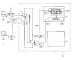
- the network relay device 10 according to an example of the present embodiment includes a plurality of ports 11, a control unit 12, a storage unit 13, and a communication unit 14, as illustrated in FIG.
- the port 11 is an example of a communication port according to the present invention.
- the port 11 is connected to a terminal device 40 such as a personal computer and outputs data received from the connection destination to the control unit 12.
- the port 11 sends data input from the control unit 12 to the connection destination.
- the control unit 12 includes a program control device such as a CPU, and operates according to a program stored in the storage unit 13.
- the control unit 12 functionally includes a redirect unit 1 and at least one (m) switch units 2 and executes processing as each. Details of the processing of the control unit 12 will be described later.
- the storage unit 13 is a memory device or the like, and holds a program executed by the control unit 12.
- This program may be provided by being stored in a computer-readable recording medium, and may be copied and stored in the storage unit 13.
- a program related to processing as the switch unit 2 can be newly created or rewritten based on an instruction received via the communication unit 14, for example. It may be.
- a program related to processing as the switch unit 2 is a program that realizes the switch unit 2 by being executed by the control unit 12.
- Each program as the switch unit 2 is associated with unique switch logic identification information.
- the program as the switch unit 2 includes instruction information representing the contents of the switching operation. Further, in this program, information for identifying the user who is the creator and authority information (whether it can be viewed or rewritten by a user other than the creator) may be recorded in association with each other.
- the control unit 12 authenticates the user and waits for an instruction to store the program in the storage unit 13, browse the program in the storage unit 13, or rewrite the program.
- the storage unit 13 receives a request for storing a program as a new switch unit 2
- the control unit 12 accepts the program related to the request, associates the authenticated user as information that identifies the creator, and stores the information.
- the authority information designated by the user is recorded in association with this program.
- a user who is a creator is set to prohibit both browsing and rewriting when he / she does not want to be seen or written by others.
- the user who is the creator may be seen by others but does not want to be rewritten, the user is allowed to browse and is set to prohibit rewriting.
- control unit 12 provides a program execution environment independent of each other such as a virtual machine or a resource container, and the switch unit provided by each program creator in each program execution environment.
- the program 2 may be operated.
- each program execution environment only a user who has been authenticated may store and operate the program.
- each program creator can execute the program as the switch unit 2 on a trial basis without being viewed by others.
- the storage unit 13 also operates as a work memory for the control unit 12.
- the communication unit 14 is, for example, a serial communication device such as a USB, and outputs the received information to the control unit 12 and transmits information according to an instruction input from the control unit 12.
- the redirect unit 1 and at least one (m) switch units 2 are functionally included.
- the control unit 12 executes processing as an operating system such as Linux (registered trademark), and the program that functions as the redirect unit 1 and the program that functions as the switch unit 2 are all programs on the operating system. Run as.
- an operating system such as Linux (registered trademark)
- an operating system such as Linux (registered trademark) is also executed as a guest OS in each virtual machine.
- at least one program as the switch unit 2 is executed on each guest OS.
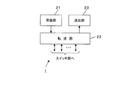
- the redirect unit 1 includes a reception unit 21, a transfer unit 22, and a transmission unit 23 as illustrated in FIG.
- the receiving unit 21 receives data from the terminal device 40 that is the connection destination via the port 11 connected to the terminal device 40.
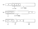
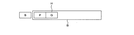
- the data received from the terminal device 40 is a packet, and includes switch logical identification information (P) for selecting the switch unit 2 and a data body (B) to be transmitted (FIG. 3A). To (c)).
- the data body (B) includes a header (H), and the header (H) includes, for example, information (Q) for specifying a transmission source and information (R) for specifying a transmission destination.
- the switch logical identification information (P) may be placed in front of the data body (B) (that is, arranged as a header for the data body (B)) (FIG. 3A), or the data body (B). ) (That is, arranged as a trailer for the data body (B)) (FIG. 3B). Further, the data body (B) may be divided into two parts, a first part (B1) and a second part (B2), and arranged between them (FIG. 3 (c)). Further, the switch logic identification information may be combined with the data body (B) by using a so-called electronic watermarking technique.
- the information specifying the transmission source and the transmission destination may be a MAC address, for example.
- the header (H) may be simply identification information of the data body.
- the transfer unit 22 extracts switch logical identification information from the data received by the receiving unit 21.
- the transfer unit 22 selects the switch unit 2 specified by the extracted switch logic identification information. That is, the program as the switch unit 2 associated with the extracted switch logical identification information is read from the storage unit 13 and the control unit 12 starts (starts) execution. Then, the transfer unit 22 extracts at least the data body from the data received by the receiving unit 21 except for the switch logic identification information.
- the transfer unit 22 connects them to form an integral data body.
- the transfer unit 22 extracts the synthesized switch logic identification information and synthesizes the switch logic identification information. The information of the previous data body is extracted, and the data body excluding the switch logic identification information is taken out. Further, the transfer unit 22 obtains port identification information (a port number or the like set in advance for the port 11) for identifying the port 11 from which the receiving unit 21 has received data. Then, the transfer unit 22 transfers the data including the port identification information and the data body extracted from the data received by the receiving unit 21 to the selected switch unit 2. That is, the data is transferred to the processing (process) of the program as the switch unit 2 that has started execution.
- the transfer unit 22 replaces the above processing with port identification information for identifying the port 11 that has received the broadcast data (set to the port 11 in advance). And the received data may be transferred to each switch unit 2 together with the port identification information.
- each of the programs as the switch unit 2 stored in the storage unit 13 is activated, and the received data is transferred to the processing (process) of each program.
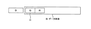
- the sending unit 23 sends data including information (D) and a data body (B) for specifying the port 11 as an output destination from the switch unit 2 to which the transfer unit 22 has transferred data.
- This data body (B) includes a header (H).
- the sending unit 23 removes information specifying the port 11 included in the received data and takes out the data body. Then, the sending unit 23 sends the data including the extracted data body via the port 11 serving as an output destination specified by the information included in the received data.
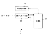
- the switch unit 2 is functionally configured to include a processing content holding unit 25, a virtual patch panel unit 26, and a processing unit 27 as illustrated in FIG.
- the processing content holding unit 25 is realized using, for example, a part of the storage unit 13.
- the information indicating the processing content is instruction information included in a program as the corresponding switch unit 2 stored in the storage unit 13.
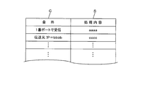
- This instruction information is, for example, port identification information or information included in at least a part of the data body such as header H (information for specifying a transmission source, information for specifying a transmission destination, etc.) as illustrated in FIG. It is defined as information associating the used condition (C) with information (S) indicating processing to be performed.
- instruction information is OpenFlow
- switch unit 2 of the present embodiment may function as an OpenFlow switch.
- instruction information may be described by a series of instruction sequences executed by the control unit 12 instead of the table information associating the condition and the process in this way. In this case, depending on the description of the instruction sequence, various processes are not limited to the switch-case type logic that can be set by the table information.
- the virtual patch panel unit 26 accepts the data transferred by the redirect unit 1 and outputs it to the processing unit 27. In addition, when data is input from the processing unit 27, the virtual patch panel unit 26 transfers the input data to the redirect unit 1.
- the processing unit 27 includes n virtual ports provided corresponding to the n ports 11 included in the redirect unit 1.
- the virtual patch panel unit 26 refers to the port identification information included in the data transferred by the redirect unit 1, and for the virtual port of the processing unit 27 corresponding to the port 11 identified by this port identification information, The data transferred by the redirect unit 1 is transferred.
- the virtual patch panel unit 26 may remove the port identification information from the data transferred to the processing unit 27 (in consideration of compatibility between the program of the processing unit 27 and the program in the conventional switch). Is).
- the virtual patch panel unit 26 provides information (port identification information) for identifying the port 11 corresponding to the input virtual port. The data is added to the input data and transferred to the redirect unit 1.
- the processing unit 27 accepts data transfer from the virtual patch panel unit 26 via one of the virtual ports.
- the specific processing of the processing unit 27 may correspond to, for example, processing in the L2 switch in the conventional network relay device. That is, the processing unit 27 extracts a header H including information (MAC address) specifying a transmission source or a transmission destination from data received through a virtual port. Then, the processing unit 27 acquires information representing a process to be performed, which is determined in advance and held in the processing content holding unit 25.
- This processing is information (corresponding to port identification information) indicating a virtual port that has received data, or at least one of information included in the extracted header H (information specifying a transmission source or transmission destination). This process is related to the information to be identified.
- the processing unit 27 includes a plurality of ports 11 of the redirect unit 1 that are unicast for sending data via the specific port 11 of the redirect unit 1 as the process represented by the acquired information. Multicast that sends data over the network, data discard, data encryption, encapsulation with header information added, data packet count and data count, other QoS control and tunnel transmission control, etc. Execute.
- the processing unit 27 executes the process represented by the acquired information, when any of the ports 11 of the redirect unit 1 is used as an output destination, the data is output via the port 11 that is the output destination. Outputs the data including the data body to the virtual patch panel unit 26 via a virtual port corresponding to the output destination port 11.
- the network relay device 10 has the above-described configuration, and operates as illustrated in FIG. In the following description, it is assumed that different instruction information is stored in advance in the processing content holding unit 25 of each switch unit 2.
- the switch logical identification information for selecting the switch unit 2 included in the data is information (slice identifier) for identifying the virtual LAN (VLAN), and the redirect unit 1 associates it with the value of each slice identifier.
- switch logical identification information for specifying the switch unit 2 as a transfer destination is associated.
- each terminal device 40a, 40b ... shall be connected to the port 11a, 11b ... of the redirect part 1, respectively.
- the user includes the switch logical identification information (slice identifier) for selecting the switch unit 2 that executes the switching process he / she wants to use, included in the data to be transmitted, and transmits it from the terminal device 40 (S1).
- the switch logical identification information (slice identifier) for selecting the switch unit 2 that executes the switching process he / she wants to use, included in the data to be transmitted, and transmits it from the terminal device 40 (S1).
- a communication program is generated and installed in advance in the terminal device 40 so as to generate the packet illustrated in FIG.
- the data transmitted from the terminal device 40a to the network relay device 10 includes switch logical identification information for selecting the switch unit 2 instructed by the user of the terminal device 40a, as illustrated in FIG.
- Such a packet (X in FIG. 7) is obtained.
- the receiving unit 21 of the redirect unit 1 of the network relay device 10 accepts this data from the terminal device 40a via the port 11a.
- the transfer unit 22 of the redirect unit 1 extracts switch logic identification information for selecting the switch unit 2 from the data received by the receiving unit 21 (S2). It is assumed that the terminal device 40a uses a conventional MAC address, and the data includes switch logical identification information for selecting the switch unit 2a.
- the transfer unit 22 removes the switch logic identification information for selecting the switch unit 2a, takes out the rest of the received data (data body), adds information (port identification information: S) for specifying the port 11a, and transfers it. Is generated (FIG. 8). Then, the transfer unit 22 transfers the generated transfer data to the selected switch unit 2a (S3).
- the port identification information may be a port 11 number (VNIC tag).
- the virtual patch panel unit 26 of the switch unit 2a accepts the data transferred by the redirect unit 1, removes the port identification information, and sets the port identification information on the virtual port of the processing unit 27 corresponding to the removed port identification information.
- the data body after the removal is output (S4).
- the processing unit 27 extracts the header H (information specifying the transmission source and the transmission destination) included in the data body received from the virtual patch panel unit 26 via any virtual port. Then, the processing unit 27 refers to the information for identifying the received virtual port (virtual port number and port identification information itself) and the information included in the extracted header H, and holds the processing content. It is checked whether or not there is a condition that the referred information satisfies among the conditions held in the unit 25.
- instruction information including the satisfied condition is acquired (S5).
- the process part 27 performs the process specified by the information contained in the said acquired instruction information (S6).
- the processing content holding unit 25 is not limited to the instruction information that associates such conditions with the processing, and may be described as a series of processing instruction sequences.
- the processing unit 27 outputs data from each virtual port corresponding to each port 11a, b,... Of the redirect unit 1 (S7).
- the virtual patch panel unit 26 When data is input through the virtual port of the processing unit 27, the virtual patch panel unit 26 adds port identification information corresponding to the virtual port to which the data is input to the input data. Then, the added data is transferred to the redirect unit 1 (S8).
- This data has the same configuration as that illustrated in FIG. As in this example, when multicasting is performed, a plurality of data to which port identification information corresponding to each of the ports 11 is added is sequentially transferred to the redirect unit 1.
- the redirect unit 1 accepts data including port identification information from the switch unit 2a as information for specifying the port 11 as an output destination.
- the sending unit 23 of the redirect unit 1 takes out the data body included in the received data and reconstructs the packet illustrated in FIG. 3 by including again the information for selecting the switch unit 2a removed in the process S3. To do. Then, the sending unit 23 sends the data of this packet through the port 11 designated by the switch unit 2a (here, all ports 11 because it is multicast) (S9).
- the processing unit 27 of the switch unit 2 receives data including the MAC address of the interface of the terminal device 40 when the terminal device 40 is activated, and the port to which the terminal device 40 is connected. 11 is received through a virtual port corresponding to 11, and information (port identification information) for specifying the virtual port is associated with a MAC address included in the received data and stored as an address table. .
- the processing unit 27 When the processing unit 27 is to send data to the transmission destination specified by the information included in the data by the processing based on the instruction information, the information (MAC address) specifying the transmission destination Is obtained from the address table, and data is transmitted via a virtual port corresponding to the port 11 represented by the port identification information.
- the switch unit 2a performs layer 2 switching (L2 switch) processing based on the conventional MAC address (48-bit length), and the switch unit 2b has 48. It is assumed that layer 2 switching (L2 switch) processing based on an extended MAC address having a bit length exceeding a bit is performed.
- L2 switch layer 2 switching
- the terminal device 40 that uses the conventional MAC address for data transmission / reception transmits the data body with the switch logical identification information for selecting the switch unit 2a, and uses the extended MAC address for data transmission / reception.
- the device 40 may send the data body with the switch logic identification information for selecting the switch unit 2b.
- the switch unit 2a performs layer 2 switching (L2 switch) processing
- the switch unit 2b performs CCN (Content Centric Network: V. Jacobson, D. K.). Smetters, J. D. Thornton, M. F. Plass, N. H. Briggs, R. L. Braynard (PARC), Networking Named Content, CoNEXT 2009, Rome, December, 2009).
- the redirect unit 1 and the switch unit 2 may be realized by separate devices.
- the network relay device 10 of this embodiment according to such an example has n ports (corresponding to communication ports of the present invention) to which the redirect unit 1 can be connected to the terminal device 40.
- a switch device having (n + k) ports of k ports connected to at least one computer device operating as the switch unit 2.
- m switch units 2 are realized by k (1 ⁇ k ⁇ m) computer devices.
- one computer device functions as one switch unit 2
- a program as the switch unit 2 is installed in the operating system of the computer device, and processing as one switch unit 2 is executed by one computer device.
- one computer device functions as a plurality of p switch units 2, for example, an environment in which p virtual machines are executed in parallel is executed on an operating system serving as a host, and each virtual machine is executed on each virtual machine.
- Operating a guest operating system installing a program for realizing an operation as the switch unit 2 in an operating system operating on each virtual machine, and executing a process as the switch unit 2 on each operating system; do it.
- one operating system may be operated for each computer device, and a program for performing processing as the redirect unit 1 may be executed on the operating system, or may be virtually executed on one computer device.
- a plurality of operating systems may be operated, and a program for performing processing as the redirect unit 1 may be executed on each operating system.
- the switch device that functions as the redirect unit 1 functionally includes a reception unit 21, a transfer unit 22, and a transmission unit 23, as in the example illustrated in FIG.
- the difference is that the transfer unit 22 and the sending unit 23 communicate with the computer device functioning as the switch unit 2 via the port 11.
- the transfer unit 22 in this example extracts switch logic identification information for selecting the switch unit 2 from the data received by the receiving unit 21.
- the transfer unit 22 selects the port 11 to which the computer device that operates as the switch unit 2 selected by the extracted switch logic identification information is connected.
- the selection of the port 11 associates the switch logic identification information for selecting the switch unit 2 in advance with the information for specifying the port 11 connected to the computer device functioning as the switch unit 2 selected by the switch logic identification information.
- the port 11 may be stored as a port selection table, and the port 11 specified by the information related to the switch logical identification information for selecting the extracted switch unit 2 may be selected by referring to the port selection table.
- the transfer unit 22 extracts from the data received by the receiving unit 21 a data body including at least information specifying the transmission source and the transmission destination. Further, the transfer unit 22 obtains port identification information (a port number or the like set in advance for the port 11) for identifying the port 11 from which the receiving unit 21 has received data. Then, the transfer unit 22 uses the port identification information and the data body including the information for specifying the extracted transmission source and transmission destination via the selected port 11 to the NIC ( Transfer to a network interface card, physical or virtual (regardless of later).
- port identification information a port number or the like set in advance for the port 11
- the transfer unit 22 replaces the above processing with port identification information (preliminarily stored in the port 11 for identifying the port 11 that has received the broadcast data). A set port number or the like) is obtained, and the received data may be transferred to each switch unit 2 together with the port identification information.
- the computer device functioning as the switch unit 2 includes a processing content holding unit 25, a virtual patch panel unit 26, and a processing unit 27, similar to the one illustrated in FIG. However, this example is different in that the virtual patch panel unit 26 receives data via the host operating system when the computer device functions as a plurality of switch units 2.
- the host operating system sets a plurality of virtual NICs corresponding to each guest operating system in the physical NIC provided in the computer apparatus. Then, the data from the redirect unit 1 is accepted via each virtual NIC. The host operating system transfers the data to the virtual patch panel unit 26 of the switch unit 2 operating on the guest operating system corresponding to the virtual NIC that has received the data.
- the virtual patch panel unit 26 accepts the transferred data and outputs it to the processing unit 27. In addition, when data is input from the processing unit 27, the virtual patch panel unit 26 transfers the input data to the redirect unit 1 via the virtual NIC of the corresponding guest operating system.
- virtual patch panel unit 26 and the processing unit 27 of one switch unit 2 may be realized as processes that operate on individual operating systems.
- a network relay device that operates in a distributed and autonomous manner without requiring any other control device, and that can be used by switching a plurality of switch units by a user. Operation becomes possible.
- FIG. 10 is an explanatory diagram showing another example of data accepted by the network relay device according to the embodiment of the present invention.
- a data encryption method the entire data including the switch logical identification information and the data body is encrypted as it is (FIG. 10A), the switch logical identification information and the data body.
- FIG. 10B there is a method of generating data with a random value (R) and encrypting them together (FIG. 10B).
- R random value
- FIG. 10B the encryption method
- the redirect unit 1 decrypts the encrypted data using the decryption key by a predetermined method, and obtains data to be output to the switch unit 2 using the decrypted data. Good.
- the redirect unit 1 may delete the random value (R) from the decoded data and obtain data to be output to the switch unit 2.
- the information specifying the key used for decryption may be transmitted together with the encrypted data body.
- information representing a known value (called magic) on the decryption side is encrypted together with the data body, and a plurality of keys that are candidates for decryption keys on the decryption side May be adopted, and when the magic included in the result of the decryption performed experimentally matches a known value, it may be determined that the tried key is a decryption key.
- the data input to the control unit 12 via the port 11 is processed by the switch unit 2 identified by the switch logic identification information. May be data in which various formats are mixed.
- the data may be Ethernet (registered trademark) frame format data.
- the control unit 12 when receiving the data, the control unit 12 refers to, for example, a value of Type included in the Ethernet (registered trademark) frame, and this value is a predetermined reserved value (for example, 0x00ff). If the type value is a predetermined reserved value, the received data is subjected to the processing described so far as including the switch logical identification information. Processing as a switch (processing handled as a packet not including switch logical identification information) may be executed.
- the redirect unit 1 ′ includes a receiving unit 21, a transfer unit 22 ′, and a sending unit 23 as illustrated in FIG.
- components having the same configuration as that shown in FIG. 2 are denoted by the same reference numerals, and detailed description thereof is omitted.
- the transfer unit 22 ′ extracts the switch logic identification information from the data received by the receiving unit 21 in accordance with the rules determined by the user through a program or the like. For example, when the switch logic identification information is included in the data as it is, this rule may be an offset value from the data head to the position where the switch logic identification information is present in the data. Note that in an example of the transfer unit 22 ′ in this case, the switch logical identification information may not be explicitly included in the data. Specifically, the transfer unit 22 'searches the data for a pattern determined for each switch logic identification information. Then, the transfer unit 22 ′ takes out the switch logic identification information determined in association with the pattern found from the data by the search.
- the user includes a predetermined pattern in the data to be transmitted in association with the switch logical identification information (slice identifier) for selecting the switch unit 2 that executes the switching process that the user wants to use. And transmitted from the terminal device 40.
- This pattern may be a specific character string, for example.
- the transfer unit 22 ' also selects the switch unit 2 specified by the switch logic identification information extracted in this way. That is, the program as the switch unit 2 associated with the extracted switch logical identification information is read from the storage unit 13 and the control unit 12 starts (starts) execution.
- the transfer unit 22 ′ removes at least the data body from the data received by the reception unit 21 except for the switch logic identification information that is explicitly included. .
- the transfer unit 22 ′ obtains port identification information (a port number or the like set in advance for the port 11) for identifying the port 11 from which the receiving unit 21 has received data. Then, the transfer unit 22 ′ transfers the data including the port identification information and the data body extracted from the data received by the receiving unit 21 to the selected switch unit 2. That is, the data is transferred to the processing (process) of the program as the switch unit 2 that has started execution.
- port identification information a port number or the like set in advance for the port 11
- the switch unit 2 includes the processing content holding unit 25, the virtual unit, as illustrated in FIG.
- the patch panel unit 26 and the processing unit 27 are included.
- the control unit 27 of the switch unit 2 performs a specific operation as a switch and a part that performs processing as a control plane (C plane) that manages logical operation as a switch.
- C plane control plane
- the data plane (D plane) is divided into parts to be processed, and some of the switch units 2 '(with a dash for distinction) include the C plane and the D plane, and the other switch units 2 " Therefore, it is possible to provide only the C plane and share the D plane of one of the switch units 2 ′.
- the processing content holding unit 25 of the switch unit 2 ′′ stores it.
- the switch unit 2 ′′ is not rewritten from the program that operates on the guest OS that operates the switch unit 2 ′.
- Such processing content holding unit 25 is set to read-only, another switch section 2 'may be rewritable set from 2 ".
- the virtual patch panel unit 26 of the switch unit 2 ′′ having only the C plane selects the control unit 27 of any switch unit 2 ′.
- the virtual patch panel unit 26 is transferred by the redirect unit 1.
- the data transferred by the redirect unit 1 is transferred to the virtual port of the selected control unit 27 corresponding to the port 11 identified by the port identification information.
- the virtual patch panel unit 26 may remove the port identification information from the data transferred to the processing unit 27 (in consideration of compatibility between the program of the processing unit 27 and the program in the conventional switch). ).
- the control unit 27 of the switch unit 2 ′ receives virtual port panels from the virtual patch panel unit 26 in the same switch unit 2 ′ or from the virtual patch panel unit 26 of another switch unit 2 ′′ having only the C plane. Data transfer is accepted via any one of the processing units 27.
- the specific processing of the processing unit 27 may correspond to, for example, processing in the L2 switch in the conventional network relay device.
- the header H including the information (MAC address) specifying the transmission source or the transmission destination is taken out from the data received through the general port, and the processing unit 27 is the same switch as the virtual patch panel unit 26 of the data transfer source From the processing content holding unit 25 included in the unit 2 ′ or the switch unit 2 ′′. To get the information that represents the process.
- the processing unit 27 includes, as processing represented by the acquired information, unicast that transmits data via a specific port 11 of the redirect unit 1, multicast that transmits data via a plurality of ports 11 of the redirect unit 1, Processing such as data discard, data encryption, encapsulation with header information added, data packet count, capacity, etc., QoS control, and transmission control via a tunnel are executed.
- the processing unit 27 executes the process represented by the acquired information, when any of the ports 11 of the redirect unit 1 is used as an output destination, the data is output via the port 11 that is the output destination. Outputs data including the data body to the virtual patch panel unit 26 of the original data transfer source through a virtual port corresponding to the output destination port 11.
- a plurality of virtual machines may be operated on the terminal device side, and an OS (Operating System) may be operated on each virtual machine.
- communication may be performed using a packet including switch logical identification information in which virtual network interfaces of the respective virtual machines are individually set.
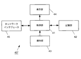
- a terminal device 40 ′′ includes a control unit 41, a storage unit 42, an operation unit 43, a display unit 44, and a network interface 45 as illustrated in FIG.
- control unit 41 is a program control device such as a CPU, and operates according to a program stored in the storage unit 42.
- the control unit 41 operates according to a program that realizes a plurality of virtual machines. Further, in the operation as each virtual machine, processing for transmitting and receiving data to and from the network relay device 10 is performed via the network.
- processing for transmitting and receiving data to and from the network relay device 10 is performed via the network.
- virtual network interfaces included in each virtual machine use different switch logical identification information.
- the storage unit 42 is a memory device or the like, and holds a program executed by the control unit 41. This program may be provided by being stored in a computer-readable recording medium such as a DVD-ROM and copied to the storage unit 42.
- the storage unit 42 may operate as a work memory for the control unit 41.
- the operation unit 43 is a keyboard, a mouse, or the like, and receives the input of the user's instruction operation, and outputs the content of the input instruction operation to the control unit 41.
- the display unit 44 is a display or the like, and displays information according to an instruction input from the control unit 41.
- the network interface 45 is a network card or the like, and in accordance with an instruction input from the control unit 41, a transmission source address (for example, a MAC address) designated by the control unit 41 and a destination address for data to be transmitted.
- An address for example, a MAC address
- switch logical identification information are added and sent to the network relay device 10 (Note that if the network relay device 10 does not need to explicitly include the switch logical identification information, The addition of the switch logical identification information may not be an explicit addition).
- the network interface 45 detects switch logical identification information included in the data received from the network relay device 10, and specifies a virtual network interface that uses the detected switch logical identification information.
- the network interface 45 outputs the received data to the identified virtual network interface.
- each OS running on each virtual machine running on each terminal device 40 ′′ receives a data transmission instruction from an application program running under the management of each OS, the following is performed: That is, the virtual network interface of the OS uses a virtual address assigned to each of the virtual network interfaces as a transmission source address, and the transmission destination address (destination) of the data instructed by the application program. And the switch logical identification information set in advance in the OS together with the data to be transmitted are output to the network interface 45.
- the network interface 45 adds the control unit 41 to the data received from the control unit 41. 41 and the destination address input from 41 And less, including the switch logic identity (as switch logic identification information described above is explicitly may not intended) and sends to the network relay device 10.
- the OS of each virtual machine transmits data using the switch unit 2 in the network relay device 10 identified by the set switch logical identification information.
- the network relay device 10 performs processing on data addressed to the terminal device 40 ′′ (addressed to a virtual network interface of any OS operating in the terminal device 40 ′′). Switch logical identification information related to
- the network interface 45 of the terminal device 40 ′′ refers to the switch logical identification information included in the data received from the network relay device 10, and to the virtual network interface of the OS that uses the referenced switch logical identification information. To output the received data.
- the terminal device 40 ′′ when the network relay device 10 has the switch unit 2 that uses an address (extended MAC address) having a bit length longer than the MAC address as the address instead of the MAC address, the terminal device 40 ′′ The OS on one virtual machine performs communication using this extended MAC address, and the OS on the other virtual machine of the terminal device 40 ′′ can perform processing using a normal MAC address. become.
- control unit 41 of the terminal device 40 ′′ operates a plurality of virtual machines
- the present embodiment is not limited to this.
- only one OS is executed by the control unit 41.
- the control unit 41 may execute the following process.
- control unit 41 accepts an instruction from the user to select one switch logical identification information from among a plurality of switch logical identification information corresponding to the plurality of switch units 2 of the network relay device 10.
- the control unit 41 When the control unit 41 accepts a data transmission instruction from an application program operating under the management of the OS, the control unit 41 sets a preset address as the transmission source address and is instructed by the transmission source address and the application program.
- the data transmission destination (destination) address and the selected switch logical identification information are output to the network interface 45 together with the data to be transmitted.
- the network interface 45 includes the source address, the destination address, and the switch logic identification information input from the control unit 41 in the data input from the control unit 41 (as described above, the switch logic The identification information may not be explicitly included) and is sent to the network relay device 10.
- data is transmitted using the switch unit 2 in the network relay device 10 identified by the switch logical identification information selected by the user.
- the storage unit 42 stores the source address and the destination address acquisition method in association with each other for each switch logical identification information that can be selected by the user.
- the transmission source address associated with the selected switch logical identification information is used as the transmission source address, and the acquisition method (acquisition processing associated with the selected switch logical identification information is used when acquiring the destination address.
- the address of the destination may be acquired.
- the network relay device 10 performs processing on data addressed to the terminal device 40 ′′ (addressed to a virtual network interface of any OS operating in the terminal device 40 ′′).
- the switch logic identification information is included (if it is not necessary to explicitly include the switch logic identification information as described above, this switch logic identification information may not be explicitly included).
- the network interface 45 of the terminal device 40 ′′ refers to the switch logic identification information included in the data received from the network relay device 10, and the switch logic identification information extracted from the data is the switch logic selected by the user. If it matches the identification information, the received data is output to the control unit 41.
- the user of the terminal device 40 ′′ selects the switch logic identification that selects the switch unit 2 that performs communication using the cache. If the information is selected, the terminal device 40 ′′ performs communication using the cache, and if the user selects the switch logical identification information for selecting the switch unit 2 that does not use the cache, the terminal device 40 ′′ is cached. In other words, the user can select whether or not to use the cache.
- switch logic identification information included in data to be transmitted may be selectable for each application program.
- the application program uses a preset address as the transmission source address, and transmits the transmission source address, the data transmission destination (destination) address, and the selected switch logical identification information to be transmitted.
- the data is output to the network interface 45 (the OS outputs the data input from the application program to the network interface 45 as it is).
- the network interface 45 includes the source address, the destination address, and the switch logical identification information (not necessarily explicit) input from the control unit 41 in the data input from the control unit 41. To the network relay device 10.
- the storage unit 42 stores the source address and the destination address acquisition method in association with each other for each switch logical identification information that can be selected by the user.
- the source address associated with the selected switch logical identification information is used as the source address, and the destination address is obtained in association with the selected switch logical identification information.
- the destination address is acquired by the acquisition method (which may be a program for performing the acquisition process).
- the network interface 45 of the terminal device 40 ′′ outputs the data received from the network relay device 10 to the control unit 41.
- the control unit 41 refers to the switch logical identification information included in this data and is included in the data. In the process of the application program in which the switch logic identification information matches the selected switch logic identification information, a process using the data is executed.
- the network relay device 10 may also perform communication with the terminal device 40 via a wireless LAN.
- the network relay device 10 may operate as a wireless LAN access point, or may operate as a wireless communication access point such as a base station for wide-area wireless communication such as 3G / 4G.
- the network relay device 10 does not include switch logical identification information (or the switch logical identification information may be ignored or deleted) with respect to an external network (for example, a conventional general network).
- the data received from the terminal device 40 may be transmitted.
- the network relay device 10 uses so-called NAT (network address translation) technology or the like, and when receiving a response from an external network, identifies which data has been sent in the past, and identifies the identified data.
- Such switch logic identification information may be added (explicitly or implicitly) to the received response data for processing.
- the network relay device 10 of the present embodiment can be connected to the general Internet, and the terminal device 40 obtains responses from various sites accessible via the Internet. Will be able to.
Landscapes
- Engineering & Computer Science (AREA)
- Computer Networks & Wireless Communication (AREA)
- Signal Processing (AREA)
- Data Exchanges In Wide-Area Networks (AREA)
Priority Applications (1)
| Application Number | Priority Date | Filing Date | Title |
|---|---|---|---|
| US14/398,453 US9413693B2 (en) | 2012-05-02 | 2013-05-01 | Network relay apparatus and program |
Applications Claiming Priority (4)
| Application Number | Priority Date | Filing Date | Title |
|---|---|---|---|
| JP2012105242 | 2012-05-02 | ||
| JP2012-105242 | 2012-05-02 | ||
| JP2012147799A JP5933371B2 (ja) | 2012-05-02 | 2012-06-29 | ネットワーク中継装置及びプログラム |
| JP2012-147799 | 2012-06-29 |
Publications (1)
| Publication Number | Publication Date |
|---|---|
| WO2013165015A1 true WO2013165015A1 (fr) | 2013-11-07 |
Family
ID=49514413
Family Applications (1)
| Application Number | Title | Priority Date | Filing Date |
|---|---|---|---|
| PCT/JP2013/062714 Ceased WO2013165015A1 (fr) | 2012-05-02 | 2013-05-01 | Dispositif relais de réseau et programme |
Country Status (3)
| Country | Link |
|---|---|
| US (1) | US9413693B2 (fr) |
| JP (1) | JP5933371B2 (fr) |
| WO (1) | WO2013165015A1 (fr) |
Families Citing this family (7)
| Publication number | Priority date | Publication date | Assignee | Title |
|---|---|---|---|---|
| US9807004B2 (en) * | 2014-04-01 | 2017-10-31 | Google Inc. | System and method for software defined routing of traffic within and between autonomous systems with enhanced flow routing, scalability and security |
| JP6570033B2 (ja) * | 2015-07-28 | 2019-09-04 | 日本電信電話株式会社 | 仮想スイッチ制御システム及び方法 |
| JP7087807B2 (ja) * | 2018-08-08 | 2022-06-21 | 日本電信電話株式会社 | サーバ、サーバシステム及びサーバのネットワーク帯域増加方法 |
| US11588733B2 (en) * | 2019-05-14 | 2023-02-21 | Vmware, Inc. | Slice-based routing |
| US11012288B2 (en) | 2019-05-14 | 2021-05-18 | Vmware, Inc. | Congestion avoidance in a slice-based network |
| LU101361B1 (en) * | 2019-08-26 | 2021-03-11 | Microsoft Technology Licensing Llc | Computer device including nested network interface controller switches |
| US12355682B2 (en) * | 2022-12-09 | 2025-07-08 | Arista Networks, Inc. | Network device having multiple forwarding domains |
Citations (2)
| Publication number | Priority date | Publication date | Assignee | Title |
|---|---|---|---|---|
| JP2002281070A (ja) * | 2001-03-19 | 2002-09-27 | Hitachi Ltd | 情報中継装置及び転送方法 |
| JP2007074283A (ja) * | 2005-09-06 | 2007-03-22 | Nippon Telegr & Teleph Corp <Ntt> | パケット転送処理装置 |
Family Cites Families (1)
| Publication number | Priority date | Publication date | Assignee | Title |
|---|---|---|---|---|
| US9967780B2 (en) * | 2013-01-03 | 2018-05-08 | Futurewei Technologies, Inc. | End-user carried location hint for content in information-centric networks |
-
2012
- 2012-06-29 JP JP2012147799A patent/JP5933371B2/ja active Active
-
2013
- 2013-05-01 US US14/398,453 patent/US9413693B2/en active Active
- 2013-05-01 WO PCT/JP2013/062714 patent/WO2013165015A1/fr not_active Ceased
Patent Citations (2)
| Publication number | Priority date | Publication date | Assignee | Title |
|---|---|---|---|---|
| JP2002281070A (ja) * | 2001-03-19 | 2002-09-27 | Hitachi Ltd | 情報中継装置及び転送方法 |
| JP2007074283A (ja) * | 2005-09-06 | 2007-03-22 | Nippon Telegr & Teleph Corp <Ntt> | パケット転送処理装置 |
Also Published As
| Publication number | Publication date |
|---|---|
| JP2013251883A (ja) | 2013-12-12 |
| JP5933371B2 (ja) | 2016-06-08 |
| US20150131671A1 (en) | 2015-05-14 |
| US9413693B2 (en) | 2016-08-09 |
Similar Documents
| Publication | Publication Date | Title |
|---|---|---|
| JP5933371B2 (ja) | ネットワーク中継装置及びプログラム | |
| RU2536347C2 (ru) | Способы и системы реализации физического устройства для дифференциации множества виртуальных машин системы хост-компьютера | |
| CN113141339B (zh) | 一种sr报文传输方法、装置及系统 | |
| JP6426879B2 (ja) | データパケット転送 | |
| JP6437693B2 (ja) | マルチキャストデータパケット転送 | |
| WO2010020151A1 (fr) | Procédé, appareil et système de traitement de paquet | |
| CN110995656B (zh) | 负载均衡方法、装置、设备及存储介质 | |
| WO2015025845A1 (fr) | Système de communication, commutateur, dispositif de commande, dispositif de gestion de données accessoires, procédé de transfert de données et programme | |
| CN106878136A (zh) | 一种报文转发方法及装置 | |
| CN107819685A (zh) | 一种数据处理的方法以及网络设备 | |
| CN107104900A (zh) | 一种组播信息处理方法和装置 | |
| JP2006166090A (ja) | 通信装置 | |
| CN101908996A (zh) | 接入私有网络的方法、数据传输方法及装置和系统 | |
| CN106209401B (zh) | 一种传输方法及装置 | |
| JP6629681B2 (ja) | スイッチ装置および中継システム | |
| US10177973B2 (en) | Communication apparatus, communication method, and communication system | |
| JP6062229B2 (ja) | 通信装置、通信方法およびコンピュータプログラム | |
| JP4933286B2 (ja) | 暗号化パケット通信システム | |
| JP5601067B2 (ja) | 中継装置 | |
| JP2007215090A (ja) | ネットワークシステム、端末およびゲートウェイ装置 | |
| JP2009207094A (ja) | リモートアクセスシステム、方法及びプログラム | |
| JP2008035300A (ja) | パケット暗号処理装置及びパケット暗号処理方法 | |
| KR102023416B1 (ko) | 네트워크 스위치 및 그것에 의해 수행되는 데이터 링크 계층에서의 암호화 구간 설정 방법 | |
| JP4934471B2 (ja) | データ通信システム | |
| CN117640289A (zh) | 基于用户态WireGuard协议的网关架构和设备 |
Legal Events
| Date | Code | Title | Description |
|---|---|---|---|
| 121 | Ep: the epo has been informed by wipo that ep was designated in this application |
Ref document number: 13785240 Country of ref document: EP Kind code of ref document: A1 |
|
| WWE | Wipo information: entry into national phase |
Ref document number: 14398453 Country of ref document: US |
|
| NENP | Non-entry into the national phase |
Ref country code: DE |
|
| 122 | Ep: pct application non-entry in european phase |
Ref document number: 13785240 Country of ref document: EP Kind code of ref document: A1 |