WO2013165017A1 - Dispositif d'ajustement de hauteur d'appareil, et dispositif d'accoudoir pour une chaise comprenant un dispositif d'ajustement de hauteur - Google Patents
Dispositif d'ajustement de hauteur d'appareil, et dispositif d'accoudoir pour une chaise comprenant un dispositif d'ajustement de hauteur Download PDFInfo
- Publication number
- WO2013165017A1 WO2013165017A1 PCT/JP2013/062761 JP2013062761W WO2013165017A1 WO 2013165017 A1 WO2013165017 A1 WO 2013165017A1 JP 2013062761 W JP2013062761 W JP 2013062761W WO 2013165017 A1 WO2013165017 A1 WO 2013165017A1
- Authority
- WO
- WIPO (PCT)
- Prior art keywords
- armrest
- rod
- vertical direction
- lock member
- support
- Prior art date
- Legal status (The legal status is an assumption and is not a legal conclusion. Google has not performed a legal analysis and makes no representation as to the accuracy of the status listed.)
- Ceased
Links
Images


Classifications
-
- A—HUMAN NECESSITIES
- A47—FURNITURE; DOMESTIC ARTICLES OR APPLIANCES; COFFEE MILLS; SPICE MILLS; SUCTION CLEANERS IN GENERAL
- A47C—CHAIRS; SOFAS; BEDS
- A47C1/00—Chairs adapted for special purposes
- A47C1/02—Reclining or easy chairs
- A47C1/022—Reclining or easy chairs having independently-adjustable supporting parts
- A47C1/03—Reclining or easy chairs having independently-adjustable supporting parts the parts being arm-rests
- A47C1/0303—Reclining or easy chairs having independently-adjustable supporting parts the parts being arm-rests adjustable rectilinearly in vertical direction
- A47C1/0305—Reclining or easy chairs having independently-adjustable supporting parts the parts being arm-rests adjustable rectilinearly in vertical direction by peg-and-notch or pawl-and-ratchet mechanism
-
- A—HUMAN NECESSITIES
- A47—FURNITURE; DOMESTIC ARTICLES OR APPLIANCES; COFFEE MILLS; SPICE MILLS; SUCTION CLEANERS IN GENERAL
- A47C—CHAIRS; SOFAS; BEDS
- A47C1/00—Chairs adapted for special purposes
- A47C1/02—Reclining or easy chairs
- A47C1/022—Reclining or easy chairs having independently-adjustable supporting parts
- A47C1/03—Reclining or easy chairs having independently-adjustable supporting parts the parts being arm-rests
- A47C1/0307—Reclining or easy chairs having independently-adjustable supporting parts the parts being arm-rests adjustable rectilinearly in horizontal direction
-
- A—HUMAN NECESSITIES
- A47—FURNITURE; DOMESTIC ARTICLES OR APPLIANCES; COFFEE MILLS; SPICE MILLS; SUCTION CLEANERS IN GENERAL
- A47C—CHAIRS; SOFAS; BEDS
- A47C1/00—Chairs adapted for special purposes
- A47C1/02—Reclining or easy chairs
- A47C1/022—Reclining or easy chairs having independently-adjustable supporting parts
- A47C1/03—Reclining or easy chairs having independently-adjustable supporting parts the parts being arm-rests
- A47C1/0308—Reclining or easy chairs having independently-adjustable supporting parts the parts being arm-rests adjustable by rotation
-
- A—HUMAN NECESSITIES
- A47—FURNITURE; DOMESTIC ARTICLES OR APPLIANCES; COFFEE MILLS; SPICE MILLS; SUCTION CLEANERS IN GENERAL
- A47C—CHAIRS; SOFAS; BEDS
- A47C7/00—Parts, details, or accessories of chairs or stools
- A47C7/54—Supports for the arms
Definitions
- the present invention relates to a height adjusting device for a furniture and a chair armrest device including the height adjusting device.
- This application claims priority based on Japanese Patent Application No. 2012-105234 filed in Japan on May 2, 2012, and Japanese Patent Application No. 2012-2322059 filed on October 19, 2012 in Japan. And the contents thereof are incorporated herein.
- Conventional height adjusting devices for chair armrest devices include the following types of devices (A) to (C).
- a cylindrical lower support rod standing on the side of the chair seat is externally fitted with an upper support cylinder provided with an armrest on the upper end so as to be vertically slidable. Are arranged in the vertical direction, and a pin or a claw that can selectively engage with the plurality of engaging portions is moved by an extension portion of an operation lever or a lever body provided on the upper support cylinder.
- Japanese Unexamined Patent Publication No. 9-173178 Japanese Unexamined Patent Publication No. 2007-190221 US Pat. No. 5,265,938 Japanese Unexamined Patent Publication No. 10-99161 US Pat. No. 6,540,300
- the extension portion of the operation lever must be formed long downward from the pivotally attached portion to the upper support cylinder, and the turning radius of the tip of the extension portion is large. Since the tip of the extension part is greatly rotated by a slight rotation of the control lever, it is difficult to accurately transmit the operation of the control lever to the tip of the extension part. The nature is great.
- the engagement depth or the disengagement distance between the plurality of engagement portions provided on the extension portion of the operation lever and the pin is more pivotal than the engagement portion closer to the distal end of the extension portion. The closer engaging portion is remarkably smaller, and the required rotation angle and operating force of the operating lever at the time of locking and unlocking vary depending on the height of the armrest, and the operability is poor.
- the vertical length of the upper support cylinder must be increased, and the vertical length of the lower support rod must be increased accordingly.
- the entire armrest becomes larger and the material cost increases. If the length of the entire armrest in the vertical direction becomes large, the mounting position of the lower support rod on the chair main body becomes remarkably lower, the mounting site is restricted, and the armrest becomes too conspicuous in terms of design. For this purpose, it is preferable that the length of the entire armrest in the vertical direction does not become large even if the movement stroke is large.
- the armrests move up and down along a linear trajectory, but when the lower support rod and the upper support tube are curved, the armrests are the lower support rod and the upper portion. It moves up and down along a curved locus along the support tube. In this case, it is conceivable that misalignment occurs in the engagement relationship between the extended portion of the operating lever provided in the upper support cylinder or the engaging portion provided in the lever body and the lower support rod, resulting in poor operation.
- the present invention has been made in view of the above-described problems of the prior art. Even when the movement stroke of the moving member is increased, the plurality of engaging portions are not exposed to the outside. Smooth operation with the operating lever provided on the moving member regardless of the vertical position or lift trajectory, light and easy locking and unlocking operation under the same conditions regardless of the vertical position of the moving member, Provided are a height adjusting device for a furniture and a chair armrest device including the height adjusting device for the purpose of reducing the risk of operation.
- a support body and a plurality of engaging portions which are mounted on the support body so as to be movable in the vertical direction and are arranged in the vertical direction are provided inside. It is movable in the horizontal direction to a movable member extending in the vertical direction, a lock position for selectively engaging one of the engaging portions of the moving member, and an unlocked position for releasing from the engaging portion, and the vertical position
- a locking member provided on the support body so as not to move in a direction, an urging means provided on the support body for urging the locking member toward the lock position, and provided on the moving member for the movement.
- an action portion that is movable in the vertical direction with respect to the support body and the lock member and that can be slid up and down with respect to the lock member even when moved in the vertical direction remains engaged with the lock member.
- the actuating member that can move the lock member in the unlocked position direction even at the position, and the actuating member provided on the moving member and moving the lock member in the unlocked position direction via the actuating member And an operating member for operating the member.
- the movable member can be held at an arbitrary height by selectively engaging the lock member provided on the support body with the plurality of engaging portions provided inside the movable member. Even if the moving stroke of the moving member is made large, the plurality of engaging portions are not exposed to the outside, and the appearance of the fixture to which the device is applied is improved.
- the operating member is operated by an operation lever provided on the moving member, and the moving member can be moved up and down by moving the lock member provided on the support body from the lock position to the unlock position.
- the lock member After the moving member is adjusted to an arbitrary height, the lock member is pushed from the unlocked position to the locked position by the urging force of the urging means by releasing the operation lever, and a plurality of engaging portions of the moving member And the moving member is locked at that height.
- the actuating member keeps the operating part that can slide up and down with respect to the lock member in any up / down position moved up and down together with the moving member, and is always operated by the operation lever regardless of the up / down position of the moving member. enable.
- the actuating member and the lock member are provided separately on the support and the moving member. However, since their engagement relationship is kept the same regardless of the vertical position of the moving member, these linked operations are maintained well.
- the operation by the operation lever provided on the moving member is made smooth.
- the support and the support are mounted so as to be movable in the vertical direction, and have a plurality of engaging portions arranged in the vertical direction. Movable in the horizontal direction, movable in the vertical direction, and in the unlocked position in which it is disengaged from the engaging portion.
- a locking member provided on the support as impossible, a biasing means provided on the support for biasing the lock member toward the lock position, and parallel to the moving member and facing upward and downward.
- a rotating rod that is mounted on the moving member so as to be rotatable about an axis, and is movable in the vertical direction with respect to the support and the lock member together with the moving member, and a rotating rod in one direction.
- the locking member by movement
- a linkage mechanism that links the pivot rod and the lock member so as to move in the unlock position direction, and an operation lever that is provided on the movable member and pivots the pivot rod around an axis that faces in the vertical direction.
- the lock member when the rotary lever is rotated around the axis line in the vertical direction by the operating lever provided on the moving member, the lock member is biased by the biasing means via the linkage mechanism. Against this, it is moved to the unlock position, and the lock member is disengaged from the engaging portion of the moving member, so that the moving member can be moved to an arbitrary height. If the hand is released from the operation lever while the moving member is held at an arbitrary height, the lock member is pushed to the lock position by the urging force of the urging means, and any of the plurality of engaging portions of the moving member is selected. Engage the heel and lock the moving member at its height.
- the lock member can be engaged with any of the engaging portions by slightly moving the moving member up and down.
- the rotating rod only moves up and down with the moving member relative to the locking member, and the relationship between the rotating rod, the locking member, and the linkage mechanism does not change at all. Even if it is positioned at the same position, it is possible to easily perform locking and unlocking operations under the same conditions.
- the relationship between the rotating rod, the lock member, and the linkage mechanism does not fluctuate, the possibility of erroneous operation and malfunction can be reduced.
- the pivot rod is inserted into a through hole provided in the lock member facing the vertical direction so as to be rotatable, and the linkage is performed.
- a mechanism is provided on the inner surface of the insertion hole of the lock member, and is provided on the outer peripheral surface of the rotating rod, and is directed in the up-down direction so that the protrusion is fitted to be relatively movable.
- the linkage mechanism can have a simple structure including a protrusion provided on the lock member and a concave groove provided on the rotating rod. Further, even if the height of the moving member fluctuates, the vertical position of the operating portion of the rotating rod contacting the protruding portion of the locking member only changes, and the protruding portion of the locking member can be moved from the rotation center of the rotating rod. The distance to the abutment point does not fluctuate, so the operating force that moves the lock member to the unlock position does not fluctuate, regardless of the height of the moving member. Under certain conditions, it can be easily locked and unlocked.
- a contact surface that is parallel to the central axis of the rotating rod is formed on a part of the rotating rod. Then, the rotating rod is rotated by pushing the eccentric portion of the contact surface with one end portion of the operating lever provided on the moving member.
- the operating lever can be rotated with a slight force, and the operating lever is pivotally attached to the moving member with a pivot, for example, a straight line in the front-rear direction.
- a pivot for example, a straight line in the front-rear direction.
- Any system, such as an advancing and retracting system that moves, can be adopted, and the degree of freedom of design increases.
- the lock member is supported to be tiltable by the support.
- the lock member when the moving member moves up and down along a curved locus with respect to the support body, the lock member is supported by the support body even if the actuating member or the rotating rod is inclined with respect to the lock member.
- the engagement relationship between the operating member or the action portion of the rotary rod and the lock member is kept equal regardless of the vertical position of the moving member. That is, the operation by the operation lever provided on the moving member is made smooth regardless of the vertical position of the moving member and the elevation trajectory.
- the lock member is provided around the axis of the engaging projection that is provided so as to be engaged with the engaging portion. Tilt to.
- the engaging protrusion of the lock member can be used as the tilt shaft of the lock member, and the structure for tilting the lock member can be simplified.
- the guide member is fixed inside the moving member and has the plurality of engaging portions and faces in the vertical direction. Is provided.
- the engaging portion is formed on the guide member which is a separate member from the moving member, and is formed inside the moving member.
- the guide member has a plurality of engagement holes as the plurality of engagement portions.
- the support body in the height adjusting device in the furniture is a lower support rod that stands on the side of the seat of the chair and has a cylindrical upper end, and a moving member
- the upper support cylinder is provided with an armrest on the upper end and is externally fitted to the lower support rod so as to be slidable in the vertical direction, and has a plurality of engaging portions on the inner side.
- the armrest can be adjusted in height with respect to the lower support rod by being arranged at the upper end portion of the lower support rod and inserting the actuating member or the rotating rod into the inside from the upper end portion of the lower support rod.
- the plurality of engaging portions are not exposed to the outside, and the operation by the operation lever provided on the moving member is performed regardless of the vertical position of the moving member or the lifting locus.
- a height adjustment device for fixtures intended to be smooth, to be easily locked and unlocked under the same conditions regardless of the vertical position of the moving member, and to reduce the possibility of erroneous operation and malfunction.
- a chair armrest device comprising the same.
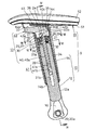
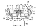
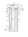
- FIG. 3 is an enlarged longitudinal sectional side view of the armrest strut in the armrest device of FIG. 2 cut along a vertical plane including its central axis.
- FIG. 4 is a sectional view taken along line IV-IV in FIG. 3. It is the perspective view which looked at the rotation collar in the armrest apparatus of FIG. 2 from the direction opposite to the direction in FIG.
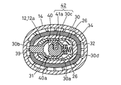
- FIG. 4 is a sectional view taken along line VI-VI in FIG. 3.
- FIG. 7 is a sectional view taken along line VII-VII in FIG. 3.
- FIG. 18 is a cross-sectional view taken along the line IV-IV in FIG. 17 before operating the operation lever in the second embodiment of the present invention.
- FIG. 21 is a cross-sectional view when the operation lever is operated with respect to FIG. 20.
- FIG. 18 is a cross-sectional view taken along the line IV-IV in FIG. 17 before operating the operation lever in the second embodiment of the present invention. It is sectional drawing when operating an operation lever with respect to FIG.
- FIG. 25 is a cross-sectional view when the operation lever is operated with respect to FIG. 24. It is the IV-IV sectional view taken on the line of FIG.
- this chair has a column 3 standing upright at the center of five radially extending legs 2 provided with casters 1 at the tip, and a seat 4 and a backrest 5 at the upper end of the column 3.
- the supporting base 6 is supported.
- the backrest 5 is supported by a rear standing portion 7a in a pair of left and right backrest supporting rods 7 (only one of which is shown) that is substantially L-shaped in a side view, and the above-mentioned standing portions in the two backrest supporting rods 7
- the front end portion of the forward portion 7b facing forward from the lower end of 7a is fixed to both end portions of the pivot 8 that penetrates the support base 6 in the left-right direction.
- a biasing means (not shown) for biasing the backrest support rod 7 in the direction in which the backrest 5 stands up is provided via the pivot 8.
- An upper end portion of the upward projecting piece 7c provided at a portion slightly rearward from the pivot 8 in the forward portion 7b of the backrest support rod 7 is connected to the rear lower portion of the seat 4 by a shaft (not shown) facing in the left-right direction. Yes.
- the front lower portion of the seat 4 is attached to the support base 6 so as to be able to slide in the front-rear direction along the front upper surface 6a of the support base 6 inclined rearward and downward. Therefore, the seat 4 moves rearward rearward and downward as the backrest 5 tilts backward, and the front part moves rearward and downward along the front upper surface 6 a of the support base 6.
- an armrest device 9 is provided in the forward portion 7 b of the backrest supporting rod 7 further behind the upward projecting piece 7 c and in the middle portion in the front-rear direction of the forward portion 7 b. It has been.
- the armrest device 9 includes an armrest column 10 and an armrest 11 attached to the upper end thereof.
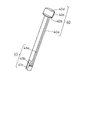
- the armrest strut 10 has a lower support rod 12 (substantially L-shaped when viewed from the front by continuously connecting an inward portion 12b facing slightly downward from the lower end of an upright portion 12a (support) facing upward and downward.
- a support body and an upper support cylinder 14 mounted on the upright portion 12a as a height adjustment device with a height adjustment device 13.
- the armrest 11 is attached to the upper end of the upper support cylinder 14.
- the inward portion 12b of the lower support rod 12 has an elliptical cross section that is long in the front-rear direction, and the cross-sectional area gradually increases inward (toward the support base 6).
- On the inner end surface of the inward portion 12b there is formed an inward protrusion 15 having a bifurcated shape in which the side shape is an oval or an ellipse that is long in the front-rear direction and the planar shape has a longitudinal groove 15a in the center.
- a recess 16 for facilitating insertion of a head 20a of a bolt 20 described later is formed from the outer end to the vicinity of the inner end of the lower surface of the inward portion 12b of the lower support rod 12. Further, in the inward portion 12b, a bolt insertion hole 17 that opens at the center portion of the longitudinal groove 15a in the inward protrusion 15 is provided in the left-right direction (the extending direction of the inward portion 12b).
- the mounting portion of the lower support rod 12 further rearward than the upward projecting piece 7c of the forward support portion 7b of the backrest support rod 7 is provided with a concave portion 18 into which the inward projection portion 15 is fitted.
- a female screw hole 19 is provided on the outer end surface of the ridge 18a facing in the up-down direction and fitted in the 15 vertical grooves 15a.
- the outer shape of the upright portion 12a of the lower support rod 12 has an elliptical cross section that is long in the front-rear direction, and the upper end portion of the upright portion 12a has a cylindrical shape by forming a recessed stepped portion 21 at the upper end. Yes. In the center of the bottom surface 21a of the recessed stepped portion 21, a recessed hole 21b extending to the lower end portion of the standing portion 12a is provided.
- a rectangular window hole 22 communicating with the recessed stepped portion 21 is provided on the upper front surface of the upright portion 12 a of the lower support rod 12. Further, a pair of front and rear engagement holes 23, 23 are provided on both sides of the upper portion of the upright portion 12a of the lower support rod 12.
- An end cap provided with a pair of left and right hanging pieces 26, 26 on the lower surface of a closing plate 25 provided with an insertion hole 24 facing the vertical direction at the center at the upper end of the upright portion 12 a of the lower support rod 12. 27 is mounted such that the drooping side pieces 26, 26 are fitted in the recessed stepped portion 21, and the lower surface of the closing plate 25 is in contact with the upper end surface of the standing portion 12a.
- the lock member 30 is slidably fitted in the front-rear direction.
- the lock member 30 has a substantially cylindrical body having an oval insertion hole 31 that is oriented in the vertical direction and is long in the front-rear direction.
- an engaging projection 30b At the front end of 30a, there is provided an engaging projection 30b that can be advanced and retracted from the front surface of the standing portion 12a through the window hole 22 in the upper end portion of the standing portion 12a of the lower support rod 12.
- a protrusion 30c facing inward is provided on either the left or right side of the inner surface of the insertion hole 31, and a spring receiving protrusion 30d is provided on the rear surface of the body 30a.
- the lower surface of the engagement protrusion 30b forms an inclined surface facing the front upper side.
- the compression coil spring 32 is in a compressed state, and its front end is fitted to the spring receiving projection 30d.
- the lock member 30 is urged forward by the compression coil spring 32, and is normally positioned at a lock position where the engagement protrusion 30b protrudes from the front surface of the standing part 12a through the window hole 22. .
- the locking member 30 is pushed rearward by a rotating rod 40 (operation member) described later, the locking protrusion 30b moves to an unlock position where the engaging protrusion 30b enters the window hole 22.
- the upper support cylinder 14 has an elliptical cylindrical shape that is long in the front-rear direction, and has an enlarged portion 14 a that has a cross-sectional area that expands upward and extends particularly forward in the upper end.
- a window hole 33 through which a part of an operation lever 43 (operation member) described later is inserted is provided at the front portion of the enlarged portion 14a.
- an inward flange portion 14 b is provided at the lower end portion of the upper support cylinder 14.
- a shallow recessed step 14c is formed on the upper surface of the enlarged portion 14a.
- an inner cylinder 34 that is externally fitted to the upright portion 12a of the lower support rod 12 so as to be slidable in the vertical direction.
- an enlarged step part 34a that is slightly enlarged from the part below it is formed, and in the center of the bottom wall 35a of the recessed step part 35 inside, there is a rotation described later.
- An insertion hole 36 through which the flange 40 is inserted is provided.
- a longitudinal groove 37 through which a part of the operation lever 43 is inserted in the front-rear direction is provided on the front surface of the enlarged step part 34a, and a rib 35b facing the up-down direction provided on the left and right inner side surfaces of the recessed step part 35 at the rear. , 35b are provided with U-shaped grooves 38, 38 for receiving the pivot 44 of the operation lever 43 and having an open upper end.
- a plurality of rectangular engagement holes 39 are arranged in the vertical direction on the front surface of the inner cylinder 34 below the enlarged step 34a.
- the lower edge of each engagement hole 39 forms an inclined surface facing rearward and downward.
- the rotary rod 40 has a large-diameter disk portion 40b connected to the upper end of a columnar shaft portion 40a concentric with the upper support cylinder 14 and the inner cylinder 34, and further has a semicircular arc shape thereon.
- the operated portion 40c is formed continuously.
- the vertical groove 41a in the vertical direction extending from directly below the disc portion 40b to the vicinity of the lower end of the shaft portion 40a, and the shaft portion 40a from the lower end portion of the vertical groove 41a.
- Crank-shaped concave groove comprising a horizontal groove 41b facing in the circumferential direction, and a vertical groove 41c in the vertical direction extending from the opposite end of the horizontal groove 41b to the lower end of the shaft portion 40a. 41 is provided.
- the planing surface serving as a semicircular chord in the operated portion 40c is parallel to the central axis of the rotary rod 40, and forms an abutting surface 40d on which an operating portion 43b of the operating lever 43, which will be described later, abuts.
- the rotary rod 40 has a lower surface of the disc portion 40b that abuts on an upper surface of the bottom wall 35a of the inner cylinder 34, and the protrusion 30c of the lock member 30 is fitted to the vertical groove 41a so as to be relatively movable.
- the shaft portion 40 a passes through the insertion hole 36 of the bottom wall 35 a of the inner cylinder 34, the insertion hole 24 of the closing plate 25 in the end cap 27, and the insertion hole 31 of the lock member 30, so that the lower support rod 12 rises. It is rotatably inserted into the concave hole 21b of the portion 12a.
- the pivot rod 41 is moved in the unlock position direction by the pivot groove 40 in one direction by the vertical groove 41a in the pivot rod 40 and the protrusion 30c in the lock member 30.
- a linkage mechanism 42 that links 40 and the lock member 30 is formed.
- the concave groove 41 (acting portion) has a crank shape because when the upper support cylinder 14 is lifted up to the upper limit together with the armrest 11, the protrusion 30c of the lock member 30 contacts the lower end of the vertical groove 41a. In contact therewith, the upper support cylinder 14 is prevented from further rising, and the pivot rod 40 is slightly rotated about the central axis during the insertion, so that it can be taken in and out of the standing portion 12a of the lower support rod 12. This is to make it possible.
- the operation lever 43 is inserted from above into the left and right U-shaped grooves 38, 38 of the inner cylinder 34 by inserting both end portions of the pivot 44 passing through the middle portion in the front-rear direction of the operation lever 43 in the left-right direction. It is rotatably mounted in the recessed step portion 35 of the inner cylinder 34, and the front operation portion 43 a passes through the vertical groove 37 of the inner cylinder 34 and the window hole 33 of the upper support cylinder 14, and opens the window. It protrudes downward from the hole 33.
- the operating portion 43b of the operation lever 43 behind the pivot 44 is hook-like in a side view and protrudes rearward, and its tip is biased laterally from the central axis of the rotary rod 40, as shown in FIG. As described above, the eccentric part of the contact surface 40d of the operated part 40c of the rotating rod 40 is in contact with the rear part.
- a closing member 45 is fitted into the recessed step 14 c at the upper end of the upper support cylinder 14 and is fixed by a set screw 46.
- An upward protrusion 47 projects from substantially the center of the upper surface of the closing member 45, and the armrest 11 is mounted on the closing member 45 by using the upward protrusion 47.
- the upper surface of the closing member 45 and the upper end surface of the upper support cylinder 14 are support surfaces that support the armrest 11, and the upward protrusion 47 is the upper end portion of the armrest column 10 that protrudes upward from the support surface.
- the inner cylinder 34 is prevented from coming off from the upper support cylinder 14 by being sandwiched from above and below by the closing member 45 and the inward flange portion 14 b of the upper support cylinder 14, and is in close contact with the elliptical upper support cylinder 14. By being internally fitted, it is prevented from rotating with respect to the upper support cylinder 14.
- the rotating rod 40 and the operation lever 43 are also prevented from coming off from the upper support cylinder 14 and the inner cylinder 34 by the closing member 45.
- the lock member 30 is urged forward by the urging force of the compression coil spring 32, and the engagement protrusion 30 b is positioned at the lock position where it is engaged with any of the engagement holes 39 of the inner cylinder 34. Accordingly, the inner cylinder 34, and the upper support cylinder 14 and the armrest 11 integrated with the inner cylinder 34 are held at appropriate heights.
- the operation portion 43a of the operation lever 43 is pushed upward against the urging force of the compression coil spring 32.
- the actuating portion 43b of the operation lever 43 is rotated downward about the pivot 44, and the eccentric portion of the contact surface 40d of the operated portion 40c of the rotating rod 40 is pushed forward at the tip thereof. Therefore, the rotating rod 40 rotates clockwise in FIGS. 7 and 6 and pushes the protrusion 30c of the lock member 30 rearward by the operating portion which is the inner surface in front of the vertical groove 41a. Therefore, the lock member 30 moves rearward against the urging force of the compression coil spring 32 and enters the unlock position.
- the lock member 30 After moving the armrest 11 to a desired height, when the hand is released from the operation portion 43 a of the operation lever 43, the lock member 30 is pushed forward by the urging force of the compression coil spring 32, and the lock member 30 The engaging protrusion 30b is fitted into any of the engaging holes 39 of the inner cylinder 34, or the distal end abuts against the inner surface of the inner cylinder 34 and stops.
- the engagement protrusion 30b is fitted into the closest engagement hole 39 only by moving the armrest 11 slightly upward or downward.
- the protrusion 30c of the lock member 30 comes into contact with the lower end of the vertical groove 41a in the concave groove 41, and the armrest 11 is prevented from further rising.
- the pivot rod 40 moves together with the armrest 11 in the vertical direction with respect to the lock member 30, and the relationship between the pivot rod 40, the lock member 30, and the linkage mechanism 42 changes at all. There is nothing. Therefore, no matter what height the armrest 11 is positioned, the locking and unlocking operations can be easily performed under the same conditions. In addition, since the relationship among the rotating rod 40, the lock member 30, and the linkage mechanism 42 does not fluctuate, the possibility of erroneous operations and malfunctions can be reduced. Further, even if the movement stroke of the armrest 11 is increased, it is not necessary to increase the length of the entire armrest 11 in the vertical direction. Therefore, the armrest device 9 can be reduced in size and the material cost can be reduced, and the chair can be reduced. The degree of freedom of the mounting position of the armrest device 9 can be increased.
- the lower support rod 12 is a support body in the fixture
- the upper support cylinder 14 is a moving member mounted on the support body so as to be movable in the vertical direction
- the inner cylinder body 34 is a moving member. It becomes a guide member which faces to the up-down direction provided with the engaging part which is fixed to a certain upper support cylinder 14 and is provided with a plurality of engaging holes 39 arranged in the up-down direction.
- the biasing means including the lock member 30 and the compression coil spring 32, the rotating rod 40, the linkage mechanism 42, and the operation lever 43 form the height adjusting device 13 in the fixture.
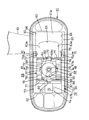
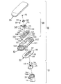
- the armrest 11 includes an armrest support plate 50 also serving as a shielding member supported by the above-described closing member 45, an armrest substrate 51 supported by the armrest support plate 50, The holding means 71 that holds the armrest support plate 50 and the armrest substrate 51 between the upper end surfaces of the armrest struts 10 so that the armrest support plate 50 and the armrest substrate 51 can move in the horizontal direction and cannot move upward, An elbow rest 52 made of an elastomer or the like is attached to the armrest substrate 51 so as to cover it.
- the above-described upward protrusion 47 that stands from the upper surface of the closing member 45 that is a receiving surface and that forms the upper end of the armrest strut 10 is formed of a pipe, and the lower end is a through-hole formed in the closing member 45. It is protruded from the upper surface of the closing member 45 by being press-fitted into the hole 53 or fixed by welding or the like. A square nut 54 is fixed to the upper end of the upward projection 47 by welding or the like.
- the armrest support plate 50 has a substantially rectangular obstruction plate whose front-rear dimension is sufficiently larger than the length of the upper surface of the upper support cylinder 14 in the front-rear direction and whose left-right dimension is long in the front-rear direction substantially the same as the width of the armrest substrate 51. 50a.
- the guide protrusion 55 has a substantially rectangular shape in plan view, with a lateral width substantially equal to the lateral dimension of the closing member 45 and a vertical dimension substantially equal to the thickness of the bottom plate 51 a of the armrest substrate 51.
- On both side surfaces of the guide protrusion 55 there are long guide surfaces (sliding contact surfaces) 55a, 55a parallel to each other in the front-rear direction.
- a long hole 56 facing in the left-right direction is formed at the center of the guide protrusion 55 so as to penetrate in the vertical direction.
- a short edge piece 57 protrudes upward from the opening edge of the upper surface of the long hole 56. ing.
- the upper end portion of the upward protrusion 47 including the square nut 54 slightly protrudes from the upper surface of the guide protrusion 55. Further, the length of the long hole 56 in the left-right direction is such that the long hole 56 is above the closing member 45 even when the armrest support plate 50 is moved to a limit position where the upward protrusion 47 abuts the end of the long hole 56. It is determined not to protrude from the end face to the side.
- an upper protrusion 58 that faces in the front-rear direction for connecting a lower holding member 67, which will be described later, protrudes upward on the upper surface of the central portion in the left-right direction of the armrest support plate 50. Yes.
- the rear end of the upward protruding piece 58 is connected to the front surface of the guide protruding portion 55.
- the vertical dimension of the front part of the upward projecting piece 58 is made larger than that of the rear part, and the upper half of the front part of the upward projecting piece 58 has a diameter larger than its plate thickness, and has a female screw in the vertical direction.
- a shaft-shaped widened portion 58 a having a hole 59 is formed.
- the armrest substrate 51 has a generally rectangular shape in which the planar shape is long in the front-rear direction.
- a protruding edge 60 protrudes obliquely outward and upward, along the inside of the protruding edge 60.
- the upright piece 61 protrudes longer than the protruding edge 60.
- the left and right opposing surfaces of the standing piece 61 are connected to each other by ribs 62, 62 protruding in the left-right direction from the upper surface of the bottom plate 51a.
- a long hole 56 provided in the guide protrusion 55 is formed in the bottom plate 51a of the arm plate 51 at the center portion of the bottom plate 51a, that is, the portion of the bottom plate 51a surrounded by the front and rear ribs 62 and the standing pieces 61 facing in the left-right direction.
- a wide opening 63 extending in the front-rear direction orthogonal to the front is formed.
- the opening 63 has a substantially rectangular shape in plan view, and the left and right opposing surfaces are a pair of guided surfaces 63a and 63a with which the left and right guide surfaces 55a of the guide protrusion 55 described above are in sliding contact.
- the opening 63 is always closed by the armrest support plate 50.
- the front and rear and left and right dimensions of the armrest support plate 50 are such that the opening 63 is closed by the armrest support plate 50 even when the armrest 11 is moved to the maximum in the front and rear and left and right directions, as will be described later. A finger or a foreign object does not enter the opening 63.
- the armrest substrate 51 When the opening 63 of the armrest substrate 51 is fitted into the guide protrusion 55 of the armrest support plate 50, the left and right guide surfaces 55a of the guide protrusion 55 are in sliding contact with the left and right guided surfaces 63a of the opening 63. Therefore, the armrest substrate 51 is supported on the upper surface of the armrest support plate 50 so as not to move in the left-right direction and to turn, that is, to be movable only in the front-rear direction. Thereby, the armrest board
- substrate 51 can be horizontally rotated while moving to the left-right direction which is a 1st direction with the armrest support plate 50.
- FIG. When the opening 63 is fitted to the guide protrusion 55, the upper surface of the guide protrusion 55 and the upper surface of the bottom plate 51a of the armrest substrate 51 are aligned with the same surface.
- a slit extending in the front-rear direction leading to the front end of the opening 63 and having the front end reaching the vicinity of the rib 62 at the front end of the bottom plate 51a of the armrest board 51 in front of the opening 63. 64 is formed through the bottom plate.
- a pair of left and right guided surfaces 65, 65 extending in the front-rear direction are formed on the upper surface of the inwardly protruding step portion projecting inwardly from the lower part of the standing pieces 61, 61 facing left and right. Is formed.
- a plurality of engaging grooves 66 that are recessed outwardly are formed on the inner surfaces of the second half of the guided surfaces 65, 65 facing each other.
- a holding means 71 including a lower holding member 67, an upper holding member 68, a fixing member 69 and a bolt 70 for pressing them from above is mounted on the upper surface of the central portion of the bottom plate 51 a of the armrest substrate 51.
- the armrest support plate 50 and the armrest substrate 51 are arranged in the front-rear direction in the upper surface of the central portion of the bottom plate 51a of the armrest substrate 51, that is, in the inner recess surrounded by the standing ribs 61 facing the front and rear ribs 62.
- a lower holding member 67 that is movably clamped is accommodated so as to be movable in the front-rear direction.
- the lower holding member 67 has a front-rear dimension smaller than the front-rear ribs 62, 62, and the left-right dimension is substantially equal to the dimension between the standing pieces 61 facing left and right.
- the upper surface of the bottom plate 51a can be relatively moved only in the front-rear direction.
- a fitting hole 72 that is long in the left-right direction perpendicular to the opening 63 of the armrest board 51 is formed at the center of the bottom plate 67 a of the lower holding member 67.
- the lower holding member 67 is placed on the upper surface of the bottom plate 51 a of the armrest substrate 51 by fitting the fitting hole 72 to the edge piece 57 of the guide projection 55 in the armrest support plate 50.
- the fitting hole 72 of the lower holding member 67 is fitted to the edge piece 57 of the guide protrusion 55, the armrest support plate 50 and the lower holding member 67 can be easily positioned, and their relative Movement is prevented.
- guide portions 73 and 73 having an L-shaped cross section in front view are continuously provided on both left and right edges of the bottom plate 67 a of the lower holding member 67.
- the upper and inner surfaces of the left and right guided surfaces 65, 65 of the armrest substrate 51 are in sliding contact with each other so as to be movable in the front-rear direction.
- a front piece 67b whose lower end is connected to the front end of the bottom plate 67a and whose left and right side ends are connected to the opposing surfaces of the front ends of the left and right guide portions 73 is connected to the front portion of the bottom plate 67a.
- a central portion in the left-right direction of the forward piece 67b is connected to an upper end of the widened portion 58a of the upward protruding piece 58 of the armrest support plate 50 by a screw 74 (see FIG. 8).
- a screw 74 see FIG. 8
- the forward piece 67b is screwed to the upward protruding piece 58 of the armrest support plate 50, there is an advantage that the armrest support plate 50, the armrest substrate 51, and the lower holding member 67 can be assembled in advance. Since the holding member 67 is held by the upper holding member 68 and the fixing member 69 as will be described later, the upward protruding piece 58 and the forward piece 67b may be omitted.
- downward elastic engagement pieces 75 are connected to the rear end portions of the left and right guide portions 73 so as to face the left and right guided surfaces 65.
- An engaging protrusion 75a that selectively engages with the engaging groove 66 in the rear half of the guided surface 65 is provided on the outer surface of the guide surface 65.
- a pair of front and rear guides extending in the left-right direction is provided on the upper surfaces of the front and rear ends of the bottom holding plate 67 of the lower holding member 67 adjacent to the front piece 67 b.
- the pieces 76 and 76 are erected so as to oppose each other with the fitting hole 72 interposed therebetween, and both side ends of the both guide pieces 76 are connected to opposing surfaces of the left and right guide portions 73.
- a plurality of engaging grooves 77 recessed rearward are formed on the front surface of the front guide piece 76, and a plurality of engaging grooves 77 recessed forward are formed on the rear surface of the rear guide piece 76. Yes.
- a plurality (four in this example) of ridges 78 extend in the left-right direction and are parallel to each other. It is installed.
- the upper holding member 68 is housed in an inward recess surrounded by the left and right guide portions 73 and the front and rear guide pieces 76 in the lower holding member 67 so as not to move in the front-rear direction.
- the front-rear dimension of the upper holding member 68 is slidable with respect to the opposing surface of the guide piece 76 of the lower holding member 67, and the left-right dimension is movable in the left-right direction between the pair of guide pieces 76.
- it is smaller than the length between the opposing surfaces of both guide parts 73.
- the upper holding member 68 can move in the left-right direction with respect to the lower holding member 67 and cannot rotate.
- the lower surface of the upper holding member 68 is placed on a plurality of protrusions 78 protruding from the bottom plate 67a of the lower holding member 67, and the contact area between the lower holding member 67 and the upper holding member 68 is reduced.
- the sliding frictional resistance when the upper holding member 68 moves in the left-right direction with respect to the lower holding member 67 is reduced.
- a hook-shaped elastic engagement member engaged from above with the front and rear guide pieces 76 and 76 of the lower holding member 67 is provided. Joint pieces 79 and 79 project outward.
- Each elastic engagement piece 79 is elastically deformable outward, and an engagement protrusion 80 (see FIG. 10) provided on the inner surface thereof is selectively formed in a plurality of engagement grooves 77 in the front and rear guide pieces 76.
- a cylindrical fitting protrusion 81 having an outer diameter substantially equal to the front-rear width of the long hole 56 of the armrest support plate 50 protrudes downward.
- the fitting projection 81 is slidably fitted into the long hole 56 and is pivotally fitted to the upward projection 47 of the closing member 45 so that the upper holding member 68 is moved to the lower holding member.
- 67 is mounted on the upper surface of the bottom plate 67 a so as to be movable in the left-right direction with respect to the lower holding member 67 and to be rotatable with respect to the closing member 45.
- the fitting protrusion 81 functions as a spacer that keeps the vertical dimension between the closing member 45 and the upper holding member 68 constant.
- the armrest strut 10 can support the armrest 11 more strongly.
- the circular fixing member 69 described above is rotatably accommodated in a circular concave portion 82 formed on the upper surface of the central portion of the upper holding member 68 in a plan view.
- a circular protrusion 69a protrudes downward.
- the circular protrusion 69a is rotatably fitted in a diameter-enlarged portion of a stepped fitting hole 83 formed on the upper surface of the recess 82 (see FIG. 12).
- a protruding piece 69b protrudes rearward.
- the protruding piece 69b is slidably in contact with the upper surface of the stepped portion 84 formed on the upper surface of the rear portion of the upper holding member 68.
- the fixing member 69 is screwed into the square nut 54 of the upward projecting portion 47 of the closing member 45 from above by inserting a bolt 70 into a vertical stepped through hole 85 formed in the center thereof.
- the fixing member 69 is configured to press the armrest support plate 50, the armrest substrate 51, the lower holding member 67, and the upper holding member 68 sequentially against the upper surface of the closing member 45 from above in the recess 82 of the upper holding member 68.
- the upper projection 47 is fixed to the upper end.
- the square nut of the upward projection 47 is provided so that the lower surface of the fixing member 69 does not strongly contact the upper surface of the upper holding member 68, that is, the upper holding member 68 can rotate with respect to the fixing member 69. 54 is fixed.
- a plurality of engagement grooves 87 facing in the vertical direction are formed on the front surface of the fan-shaped thick portion 86 formed in the front portion of the fixing member 69 along the circumferential direction.
- a square hole 88 is formed in the front part of the upper holding member 68 that faces the thick part 86 and faces upward and downward, with an upper surface and a rear surface opening.
- An elastic body 89 such as rubber is fitted in the square hole 88. (See FIG. 9).
- a locking pin 90 that faces in the vertical direction is sandwiched between the rear surface of the central portion in the left-right direction of the elastic body 89 and the facing surface of the engaging groove 87 so as to be urged backward by the elastic body 89. ing.
- the entire armrest 11 including the upper holding member 68 is applied with an appropriate resistance around the fixing member 69. Moreover, it can be rotated by a predetermined angle with a sense of moderation.
- the fixing member 69 having the engaging groove 87, the elastic body 89 inserted into the square hole 88 of the upper holding member 68, and the locking pin 90 provide a resistance force that applies a resistance force to the horizontal rotation of the armrest 11. Configure the means.
- FIG. 13 shows an example in which the elbow rest 52 located at the rear limit shown in FIG. 10 is moved to the front limit (the elbow rest is not shown).
- the armrest support plate 50 and the armrest support plate 51 are fitted to the upward protrusion 47 of the closing member 45 so as not to move forward and backward.
- the lower holding member 67 is connected to the upper holding member 67 so as not to move in the front-rear direction
- the upper holding member 68 is attached to the upper surface of the lower holding member 67 so as not to move in the front-rear direction, and is screwed to the upward protrusion 47 of the closing member 45. Only the armrest substrate 51 and the armrest 52 move relative to the fixed member 69 thus moved forward.
- a pair of left and right elastic engagement pieces 75, 75 at the rear end of the lower holding member 67 are provided at the rear of the pair of left and right guided surfaces 65, 65 on the armrest board 51.
- the armrest substrate 51 moves to the front limit position with a sense of moderation.
- the front / rear and left / right dimensions of the armrest support plate 50 are such that the opening 63 of the armrest substrate 51 is always closed, so that even if the armrest substrate 51 is moved to the front / rear limit position, There is no possibility of foreign objects entering.
- the front-rear position of the armrest board 51 can be adjusted step by step by the number of the engagement grooves 66, it can be adjusted to an arbitrary intermediate position.
- FIG. 14 shows an example in which the position of the left and right direction is adjusted by translating the elbow rest 52 in the left and right direction, that is, outward.
- the armrest support plate 50, the armrest substrate 51, and the lower holding member 67 move outward with respect to the upper holding member 68
- the pair of front and rear elastic engagement pieces 79 of the upper holding member 68 are held by the lower holding member.
- the member 67 is translated inward along a pair of front and rear guide pieces 76.
- the engagement protrusions 80 of the front and rear elastic engagement pieces 79 are selectively engaged with the plurality of engagement grooves 77 provided in the front and rear guide pieces 76, thereby adjusting the left and right positions of the elbow rest 52.
- the opening 63 of the armrest substrate 51 is fitted to the guide protrusion 55 of the armrest support plate 50 so as not to be relatively movable in the left-right direction, so that the armrest support plate 50 is moved together with the armrest substrate 51 in the left-right direction. Moving. Therefore, even if the elbow rest 52 is moved to the maximum in the left-right direction, the opening 63 of the armrest substrate 51 is not exposed to the outside, and there is no possibility that a finger or a foreign object enters the opening 63.
- the armrest support plate 50 can stably support the armrest 52, and the armrest support plate 50 and the armrest substrate 51 Since they do not slide relative to each other in the left-right direction, it is possible to prevent wear of the contact surfaces.
- FIG. 15 shows an example in which the armrest 52 is rotated counterclockwise in plan view with respect to the armrest column 10 and the orientation in the left-right direction is adjusted.
- the armrest support plate 50, the armrest substrate 51, the lower holding member 67 and the upper holding member 68 are rotated relative to the fixing member 69.
- the locking pin 90 urged rearward by the elastic body 89 fitted in the square hole 88 of the upper holding member 68 is elastically engaged.
- the engagement grooves 87 sequentially change one by one, and the horizontal direction of the elbow rest 52 is adjusted. This adjustment can be performed stepwise and with a modest feeling by the number of the engagement grooves 87.
- the armrest support plate 50 rotates together with the armrest substrate 51. Therefore, even if the horizontal direction of the elbow rest 52 is adjusted, the opening 63 is not exposed to the outside, and there is no possibility that a finger or a foreign object enters the opening 63. Moreover, since the positional relationship in the left-right direction between the armrest support plate 50 and the armrest substrate 51 is not changed, the armrest 52 can be stably supported and the wear of the contact surfaces can be prevented.
- the armrest substrate is interposed between the upper surface of the closing member 45 fixed to the upper end portion of the upper support cylinder 14 that is the upper end of the armrest column 10 and the armrest substrate 51.
- An armrest support plate 50 having a large front-rear and left-right dimension for supporting 51 is provided.
- a wide guide protrusion 55 projecting from the upper surface of the armrest support plate 50 can be relatively moved in the front-rear direction, relatively unmovable in the left-right direction, and relative to the wide opening 63 provided on the armrest substrate 51.
- the armrest substrate 51 can be supported by the armrest support plate 50 with a wide support area even if the elbow rest 52 is moved in the left-right direction or rotated. Accordingly, the armrest 52 can be stably supported by the armrest support 10 via the armrest support plate 50. In addition, the elbow rest 52 can be stably moved in the front-rear direction while guiding the armrest substrate 51 by the guide projection 55 fitted in the wide opening 63. In particular, even if the elbow rest 52 is horizontally rotated, the lower surface of the armrest substrate 51 is widely supported. Therefore, even if the elbow rest is placed on the horizontally pivoted elbow rest 52, the elbow rest 52 may swing up and down, The possibility that a bending load is applied to the upward protrusion 47 is reduced.
- the armrest substrate 51 is sandwiched from above and below by the armrest support plate 50 having a large front and rear left and right dimension and the lower holding member 67 connected thereto, the armrest 52 is prevented from wobbling in the vertical direction, It can be moved stably in either direction.
- the armrest support plate 50 moves in the left-right direction together with the armrest substrate 51 and rotates to widely support the lower surface of the armrest substrate 51. Therefore, even if the elbow rest 52 is moved in the front / rear / left / right direction or the elbow is placed in a state where it is horizontally rotated, the elbow rest 52 may wobble in the vertical direction or a bending load may be applied to the upward projection 47. The sex becomes smaller.
- a pair of guided surfaces 65 opposed to each other with the opening 63 interposed therebetween are provided on the left and right sides in the recess of the armrest substrate 51, and the guided surfaces 65 are provided on the left and right sides of the lower holding member 67.
- the pair of guide portions 73 are guided so as to be relatively movable in the front-rear direction. Therefore, the elbow rest 52 can be stably moved in the front-rear direction, and the contact area and sliding resistance between the armrest substrate 51 and the lower holding member 67 are reduced, so that the elbow rest 52 can be smoothly moved in the front-rear direction. be able to.
- the pair of guided surfaces 65 are provided in the recesses of the armrest substrate 51, the height of the armrest substrate 51 does not increase.
- the upward protrusion 47 is fitted into the elongated hole 56 of the guide protrusion 55, and the vertical dimension of the guide protrusion 55 is substantially equal to the thickness of the bottom plate 51 a of the armrest substrate 51, and the lower holding member 67 is an armrest substrate 51, the upper holding member 68 is accommodated in the recess on the upper surface of the lower holding member 67, and the fixing member 69 is accommodated in the recess 82 on the upper surface of the upper holding member 68, respectively. Therefore, the members constituting the holding means 71 can be easily mounted only by overlapping the lower members in order in the recesses on the upper surface of the armrest substrate 51.
- the holding means 71 is composed of a plurality of upper and lower members, the overall height of the holding means 71 can be kept low, and the vertical dimensions of the armrest substrate 51 and the armrest 11 as a whole can also be reduced. As a result, material costs for molding the armrest substrate 51 and the armrest 52 are saved, and the appearance of the armrest device 9 is improved.
- the fixing member 69 is accommodated in the concave portion 82 on the upper surface of the upper holding member 68, and the engaging groove 87, the elastic body 89, and the locking pin 90 are provided between the outer peripheral surface of the fixing member 69 and the opposing surface of the upper holding member 68. Since the resistance applying means for the armrest 11 is provided, the height of the resistance applying means can be kept low.
- the upward projection 47 of the armrest column 10 is indirectly fitted into the opening 63 of the armrest substrate 51 and the fitting hole 72 of the lower holding member 67 through the guide projection 55 protruding from the armrest support plate 50. Has been. Therefore, the load when the elbow rest 52 is moved in the front / rear / right / left direction with respect to the armrest strut 10 or rotated is directly applied to the sliding portion between the upward protrusion 47, the opening 63, and the fitting hole 72. The wear of these contact surfaces is suppressed without being added, and the elbow rest 52 can be smoothly moved over a long period of time.
- the armrest substrate 51 and the armrest support plate 50 are moved together. Therefore, by setting the width in the left-right direction of the armrest support plate 50 to a dimension not less than the width in the left-right direction of the opening 63 of the armrest substrate 51 and not more than the width in the left-right direction of the armrest substrate 51, Even if it exists in this position, the armrest support plate 50 does not protrude to the left-right outer side of the armrest 11, and can maintain an external appearance favorably.
- first direction and the second direction are the left-right direction and the front-rear direction orthogonal to each other in the horizontal plane, but the first direction and the second direction are not limited to the two orthogonal directions, Any two directions that intersect each other can be used.
- FIG. 16 shows a modification of the armrest.
- This armrest 91 employs the left-right direction movement guide mechanism as the first direction in the armrest 11 of the first embodiment shown in FIGS. 1 to 15 (particularly see FIG. 2) as the front-rear direction movement guide mechanism.
- the movement guide mechanism in the front-rear direction as the second direction is adopted as the movement guide mechanism in the left-right direction. Therefore, also in this modification, the first direction is the left-right direction and the second direction is the front-rear direction.
- the armrest 91 includes an armrest support plate 92 corresponding to the armrest support plate 50, an armrest substrate 93 corresponding to the armrest substrate 51, a holding means 106 corresponding to the holding means 71, and an armrest 94 corresponding to the armrest 52. It has.
- the armrest support plate 92 is a closing plate 96 formed so that the front-rear dimension is a dimension between the front-rear dimension of the opening 95 long in the front-rear direction provided on the armrest substrate 93 and the front-rear dimension of the armrest substrate 93. And a guide protrusion 97 provided on the upper surface of the closing plate 96. A long hole 98 facing in the front-rear direction is formed in the guide protrusion 97 so as to penetrate in the vertical direction, and a short edge piece 99 protrudes upward from the opening edge of the upper surface of the long hole 98. .
- the armrest support plate 92 is relatively movable in the front-rear direction, not relatively movable in the left-right direction, by fitting the upward protrusion 47 of the closing member 45 into the elongated hole 98 of the guide protrusion 97 so as to be relatively movable. It is supported by the upper surface of the closing member 45 so as to be horizontally rotatable around the upward protrusion 47.
- An opening 95 that faces in the front-rear direction is formed at the center of the bottom plate 100 in the armrest substrate 93.
- the opening 95 is always closed by the closing plate 96 of the armrest support plate 92. That is, the front and rear and left and right dimensions of the closing plate 96 are such that the entire opening 95 is closed by the closing plate 96 even when the armrest substrate 93 is moved to the maximum in the front and rear and left and right directions, as will be described later. Foreign matter does not enter the opening 95.
- the armrest substrate 93 By fitting the opening 95 of the armrest substrate 93 to the guide protrusion 97 of the armrest support plate 92 so as not to be relatively movable in the front-rear direction, to be relatively movable in the left-right direction, and not to be relatively rotatable, the armrest substrate 93 is
- the armrest support plate 92 is supported on the upper surface of the armrest support plate 92 so as to be relatively movable only in the left-right direction.
- the armrest substrate 93 moves in the front-rear direction, which is the second direction, together with the armrest support plate 92 and can be horizontally rotated.
- Guide pieces 102, 102 extending in the left-right direction are provided between the left and right standing pieces 101, 101 on the outer side of the front and rear end edges of the opening 95 in the armrest substrate 93, and the outer surfaces thereof are recessed inwardly, respectively.
- a plurality of engaging grooves 103 are formed.
- a holding means 106 including a lower holding member 104, an upper holding member 105, a fixing member 69, and a bolt 70 is attached to the upper surface of the central portion of the bottom plate 100 of the armrest substrate 93.
- the armrest In the upper surface of the central portion of the bottom plate 100 of the armrest substrate 93, that is, in the inner recess surrounded by the front and rear guide pieces 102 and the left and right standing pieces 101, the armrest is supported by the armrest support plate 92 on the upper surface of the bottom plate 100.
- a lower holding member 104 that holds the substrate 93 movably in the front-rear and left-right directions is accommodated so as to be movable in the left-right direction.
- the lower holding member 104 has a left-right dimension smaller than a dimension between the left and right standing pieces 101, 101, and a front-rear dimension substantially equal to a dimension between the guide pieces 102, 102 opposed to the front and rear. It can move relative to the armrest substrate 93 only in the left-right direction.
- a rectangular recess 107 facing in the front-rear direction is provided at the center of the lower holding member 104, and a fitting hole 109 extending in the front-rear direction is formed in the bottom plate 108 of the recess 107.
- the lower holding member 104 is placed on the upper surface of the bottom plate 100 of the armrest substrate 93 with the fitting hole 109 fitted to the edge piece 99 of the guide projection 97 in the armrest support plate 92.
- a plurality of engaging grooves 111 that are recessed inward are formed on the outer surfaces of the left and right standing parts 110 of the lower holding member 104.
- hook-shaped elastic engagement pieces 112, 112 that engage the front and rear guide pieces 102 from above are provided at the front and rear ends of the lower holding member 104, and the inner surfaces of the lower ends of the elastic engagement pieces 112 are provided.
- the plurality of engaging grooves 103 provided in each guide piece 102 can be elastically engaged.
- the upper holding member 105 is accommodated on the upper surface of the bottom plate 108 of the recess 107 in the lower holding member 104.
- the left and right dimensions of the upper holding member 105 are slidable to the left and right inner surfaces of the recess 107 in the lower holding member 104, and the front and rear dimensions are considerably smaller than the dimension between the front and rear inner surfaces of the recess 107. .
- the upper holding member 105 can move relative to the lower holding member 104 in the front-rear direction, cannot move in the left-right direction, and cannot rotate relative to the lower holding member 104.
- hook-shaped elastic engagement pieces 113, 113 are provided, and the inner surfaces of the lower ends of both elastic engagement pieces 113, 113 are respectively shown in FIG.
- An engaging protrusion (not shown) similar to the engaging protrusion 80 is provided.
- the elastic engagement piece 113 is fitted to the left and right standing portions 110 of the lower holding member 104 from above.
- a cylindrical fitting protrusion 114 having an outer diameter substantially equal to the lateral width of the long hole 98 of the armrest support plate 92 is provided so as to protrude downward.
- the fitting projection 114 is slidably fitted into the fitting hole 109 of the lower holding member 104 and the long hole 98 of the armrest support plate 92, and is fitted to the upward projection 47 of the closing member 45 so as to be rotatable.
- the upper holding member 105 is mounted on the upper surface of the bottom plate 108 of the lower holding member 104 so as to be movable relative to the lower holding member 104 in the front-rear direction and relative to the armrest support plate 92. Has been.
- the fitting protrusion 114 has a function as a spacer that keeps the vertical dimension between the closing member 45 and the upper holding member 105 constant, and the lower end of the fitting protrusion 114 is brought into contact with the upper surface of the closing member 45. By doing so, the lower surface of the upper holding member 105 does not come into strong contact with the upper surface of the bottom plate 108 of the lower holding member 104.
- a circular fixing member 69 (see FIG. 16) is accommodated in a circular recess 115 formed on the upper surface of the central portion of the upper holding member 105 so as to be relatively rotatable.
- the armrest support plate 92 and the lower holding member 104 move together with the armrest substrate 93. Therefore, by setting the front-rear dimension of the closing plate 96 of the armrest support plate 92 to be equal to or larger than the front-rear dimension of the opening 95 of the armrest substrate 93 and equal to or smaller than the front-rear dimension of the armrest substrate 93, the entire opening 95 is always closed. Therefore, foreign matter can be prevented from entering the opening 95. Further, since the closing plate 96 does not protrude in the front-rear direction from the front-rear edge of the armrest substrate 93, the appearance can be maintained well.
- the armrest substrate 93 is moved relative to the armrest support plate 92 and the lower holding member 104 in the left-right direction. At this time, since the entire opening 95 of the armrest substrate 93 is always closed by the closing plate 96 of the armrest support plate 92, foreign matter can be prevented from entering the opening 95.
- the front-rear direction may be the first direction
- the left-right direction may be the second direction
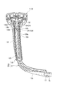
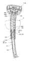
- the height adjustment device 120 according to the second embodiment includes the upright portion 12a, the upper support cylinder 14, and the inner cylinder 34 that extend linearly up and down, whereas the height adjustment device 13 according to the first embodiment has a longitudinal direction. This is particularly different in that it has an upright portion 121 (support body), a top support cylinder 122 and an inner cylinder body 123 that form a convex curved shape on the left and right outer sides in a cross-sectional view and extend vertically (see FIG. 19).
- symbol is attached
- a lock member 124 is provided instead of the lock member 30 of the first embodiment.
- the lock member 124 has a cylindrical engagement protrusion (lock pin) 125 at the front end of the body 30a, and a pin hole 126 that opens coaxially with the engagement protrusion 125 on the rear surface of the body 30a.
- a screw hole 127 coaxial with the pin hole 126 is formed in the rear wall of the upright portion 121 behind the pin hole 126.
- a shaft support screw 128 having a cylindrical tip shaft portion 128a is screwed and fixed to the screw hole 127.
- the distal end shaft portion 128a is inserted into the pin hole 126 of the body portion 30a so as to be rotatable and slidable back and forth.
- the lock member 124 can be tilted to the left and right about the distal end shaft portion 128a and the engaging protrusion 125.
- the rotary rod 130 includes a shaft portion 130a inserted into the inner cylindrical body 123, a small diameter shaft portion 130b connected to the upper portion thereof by reducing the diameter in a stepped shape, and an operation to be continued and expanded in a stepped shape above the shaft portion 130b. And the portion 130c are coaxially and linearly integrated.
- the shaft portion 130a is appropriately thinned so as to leave a longitudinal rib along the axial direction and a lateral rib perpendicular to the axial direction on the outer periphery thereof, and on the left and right outer sides (on the same side as the protruding portion 30c of the lock member 124).
- a groove 131 (acting portion) along the axial direction is formed on the outer periphery over the entire length.
- a slider 132 that can slide back and forth is disposed at the upper end of the inner cylinder 123.
- the slider 132 engages the upper locking piece 133 of the operation lever 43 at its front end.
- the upper locking piece 133 moves the slider 132 rearward when the operation portion 43a of the operation lever 43 is pushed upward.
- an engagement hole 134 is formed which has a rectangular shape in plan view and is inserted through the rotary rod 130 from above.
- Inner flanges 135 are formed on both sides of the engagement hole 134, and a flange 130 d formed on the upper end of the operated portion 130 c of the rotary rod 130 is in sliding contact with the inner flange 135 from above.
- the slider 132 is held in the upper support cylinder 122 together with the inner cylinder 123 in a state where the rotary rod 130 is inserted into the engagement hole 134 and suspended in the inner cylinder 123.
- the upper support cylinder 122 is attached to the standing part 121 of the lower support rod 12 while holding the slider 132, the inner cylinder 123, and the rotating rod 130.
- the shaft portion 130a of the rotating rod 130 is inserted into the body portion 30a of the lock member 124, and the protrusion 30c is fitted into the groove 131 so as to be relatively movable (see FIG. 22).
- the rotary rod 130 can be moved up and down integrally with the lower support rod 12 together with the slider 132, the inner cylinder 123 and the upper support tube 122, and can be tilted by a small amount with respect to the slider 132 and the like.
- a protruding piece 136 that protrudes to the inside of the engaging hole 134 is formed on the inner flange 135 on the left and right outer sides of the engaging hole 134.
- a notch 137 including a contact surface 137a formed substantially orthogonal to the circumferential direction at the substantially same circumferential position as the groove 131 is formed on the outer periphery of the operated portion 130c of the rotating rod 130.
- the rear end of the protruding piece 136 of the engagement hole 134 engages with the eccentric part of the contact surface 137a of the notch 137 from the front when the engagement hole 134 is inserted.
- the lock member 124 is urged forward by the urging force of the compression coil spring 32 when the operation lever 43 is not operated.
- the lock member 124 is a lock in which the engagement protrusion 125 is engaged with one of a plurality of circular engagement holes 139 (engagement portions) provided vertically on the front surface of the inner cylinder 123. Position. At this time, the inner cylinder 123, the upper support cylinder 122, and the armrest 11 are held at appropriate heights.
- the lock member 124 moves forward by the urging force of the compression coil spring 32, and the engaging protrusion Return to the locked position where 125 is engaged with one of the engagement holes 139 of the inner cylinder 123. Even if the tip of the engagement protrusion 125 abuts on the inner surface of the inner cylinder 123 avoiding the engagement hole 139 and stops, the engagement protrusion 125 can be moved by moving the armrest 11 slightly upward or downward. The portion 125 engages with the nearest engagement hole 139 to be in the locked position.
- the upright portion 121, the upper support cylinder 122, and the inner cylinder 123 of the lower support rod 12 are curved in a cross-sectional view in the front-rear direction.
- the up-and-down trajectory of the upper support cylinder 122 and the armrest 11 also have the same curved shape in a cross-sectional view in the front-rear direction.
- the rotating rod 130 that moves up and down together with the inner cylindrical body 123 also moves up and down in a curved shape, but the lock member 124 that passes through the rotating rod 130 is held on the upper end portion of the upright portion 121 so as to be tiltable to the left and right. Therefore, even if the pivot rod 130 changes the angle of the cross-sectional view in the front-rear direction with respect to the lower support rod 12 while sliding the concave groove 131 and the protrusion 30c as it moves up and down, the lock member 124 tilts accordingly. By doing so, the engagement relationship between the pivot rod 130 and the lock member 124 is kept constant regardless of the height of the armrest 11.
- the armrest 11 and the rotating rod 130 which are shown with a chain line in the figure show a state where they are fully lowered (a state corresponding to FIG. 18).
- the angle with respect to the upper support cylinder 122 and the like also changes. This is because the upper end portion of the pivot rod 130 can be tilted to the left and right with respect to the upper support cylinder 122 and the like, so that the engagement relationship between the pivot rod 130 and the slider 132 is kept equal regardless of the height of the armrest 11. Be drunk.
- the insertion hole 24 for the rotating rod 130 of the end cap 27 mounted on the upper end portion of the upright portion 121 above the lock member 124 has a long oval shape on the left and right. Is allowed to tilt left and right.
- the relative relationship between the rotary rod 130, the lock member 124, and the linkage mechanism 138 is substantially constant regardless of the height of the armrest 11, as in the first embodiment. At any height, a light unlocking operation can be performed under the same conditions, and the possibility of erroneous operation and malfunction can be reduced.
- the lock member 124 is supported by the lower support rod 12 so as to be tiltable. Therefore, even when the upright portion 121 of the upper support cylinder 122 or the lower support rod 12 is curved and the rotating rod 130 moves up and down along a curved locus, it depends on the vertical position of the upper support tube 122 and the rotating rod 130. Therefore, the engagement relationship between the concave groove 131 of the rotary rod 130 and the protrusion 30c of the lock member 124 can be kept equal, and the associated operation can be kept good. That is, regardless of the vertical position of the armrest 11, the operation with the operation lever 43 provided on the armrest 11 can be performed smoothly and reliably.
- the height adjustment device 140 according to this modification is particularly different in that an operating member 150 is provided instead of the rotary rod 130 of the second embodiment.
- an operating member 150 is provided instead of the rotary rod 130 of the second embodiment.
- the same components as those in the second embodiment are denoted by the same reference numerals, and detailed description thereof is omitted.
- the actuating member 150 is supported by the upper support cylinder 122 together with the relay member 153, and is attached to the lower support rod 12 and the lock member 124 together with the relay member 153, the upper support cylinder 122 and the inner cylinder 123. On the other hand, it can move up and down. Even if the actuating member 150 moves in the vertical direction, the action part (rear edge 151) that is long in the front-rear direction with respect to the lock member 124 remains engaged with the actuating member 150, and the actuating member 150 is locked at any vertical position. The member 124 can be moved in the unlock position direction (backward).
- the actuating member 150 has a strip shape extending vertically, and is disposed so as to be substantially orthogonal to the left-right direction.
- the upper end portion 152 of the operating member 150 is supported by the upper end portion of the upper support cylinder 122 so as to be movable in the front-rear direction.
- the actuating member 150 is only allowed to translate in the front-rear direction and tilt left and right with respect to the upper support cylinder 122.
- the lower part of the actuating member 150 is inserted into the trunk portion 30a of the lock member 124 together with the relay member 153 that operates in conjunction with the operation lever 43.
- the relay member 153 has a U-shaped cross-sectional shape that opens rearward and extends vertically, and the lower part of the operation member 150 is slidably sandwiched therein. The relay member 153 is allowed only to move in the vertical direction relative to the upper support cylinder 122 and to tilt integrally with the operation member 150.
- the left and right side wall portions 154 of the relay member 153 are formed with a plurality of rear-lowering slit holes 155 (upper and lower two stages in the figure). Each slit hole 155 engages with both side portions of a locking pin 156 fixed to the operating member 150. In this state, the relay member 153 and the actuating member 150 are inserted into the trunk portion 30a of the lock member 124.
- the lock member 124 is in the locked position by the urging force of the compression coil spring 32 when the operation lever 43 is not operated (see FIG. 25).
- the operation of the relay member 153 causes the lock member 124 to move rearward against the urging force together with the operation member 150 to reach the unlock position.
- the height adjusting device 140 may be configured to use the upright portion 12a, the upper support cylinder 14, the inner cylinder 34, and the lock member 30 in the height adjusting device 13 of the first embodiment.
- the height adjusting devices 13, 120, 140 are configured such that the height of the armrest 11 in the armrest device 9 of the chair can be adjusted with respect to the lower support rod 12.
- the present invention is not limited to this, and the present invention can be widely applied as a height adjustment device for a moving member that can move in the vertical direction with respect to a support in general fixtures.
- the upright portion 121, the upper support cylinder 122, and the inner cylinder 123 that are curved in a cross-sectional view in the front-rear direction are illustrated, but these may be curved in a cross-sectional view in the left-right direction.
- the present invention is not limited only to the above-described embodiments, and can be implemented in various modified modes as follows, for example, without departing from the gist of the present invention.
- Protrusions extending in the vertical direction are provided on the outer peripheral surfaces of the shaft portions 40a, 130a of the rotary rods 40, 130, and the ridges are provided in the vertical direction provided on the inner surfaces of the insertion holes 31 of the lock members 30, 124.
- the ridges are fitted into the extending ridges so as to be movable relative to each other, and one side surface of the ridges is pushed by the ridges by the rotation of the rotary rods 40 and 130, and the lock members 30 and 124 are moved from the lock position to the unlock position. Moving.
- the operation lever 43 has a pin shape that protrudes in the front-rear direction from the front surface of the upper support cylinders 14 and 122, and at the rear ends of the pins, the contact surfaces 40d and 137a facing the front of the rotary rods 40 and 130 are provided.
- the eccentric part is pushed to rotate the rotary rods 40 and 130 in a desired direction.
- the rear end portion of the pin in the above (2) and the upper end portion of the rotary rod 40, 130 are connected by a link that faces in a direction orthogonal to the rotary rod 40, 130.
- the inner cylinder bodies (guide members) 34 and 123 are not provided, but the engaging portions instead of the engaging holes 39 and 139 are directly provided on the inner walls of the upper support cylinders (moving members) 14 and 122.
- the engaging portion has a concavo-convex shape that is not exposed to the outside rather than a through hole that is exposed to the outside.
Landscapes
- Health & Medical Sciences (AREA)
- Dentistry (AREA)
- General Health & Medical Sciences (AREA)
- Seats For Vehicles (AREA)
- Rehabilitation Tools (AREA)
Priority Applications (3)
| Application Number | Priority Date | Filing Date | Title |
|---|---|---|---|
| US14/398,122 US9603451B2 (en) | 2012-05-02 | 2013-05-02 | Height adjustment device in fixture, and armrest device for chair provided with height adjustment device |
| EP13784408.0A EP2845518B1 (fr) | 2012-05-02 | 2013-05-02 | Dispositif d'ajustement de hauteur d'appareil, et dispositif d'accoudoir pour une chaise comprenant un dispositif d'ajustement de hauteur |
| CN201380022912.2A CN104486971B (zh) | 2012-05-02 | 2013-05-02 | 日常用具中的高度调节装置及具备该高度调节装置的椅子的扶手装置 |
Applications Claiming Priority (4)
| Application Number | Priority Date | Filing Date | Title |
|---|---|---|---|
| JP2012-105234 | 2012-05-02 | ||
| JP2012105234 | 2012-05-02 | ||
| JP2012232059A JP6122607B2 (ja) | 2012-05-02 | 2012-10-19 | 什器における高さ調節装置、およびそれを備える椅子の肘掛け装置 |
| JP2012-232059 | 2012-10-19 |
Publications (1)
| Publication Number | Publication Date |
|---|---|
| WO2013165017A1 true WO2013165017A1 (fr) | 2013-11-07 |
Family
ID=49514415
Family Applications (1)
| Application Number | Title | Priority Date | Filing Date |
|---|---|---|---|
| PCT/JP2013/062761 Ceased WO2013165017A1 (fr) | 2012-05-02 | 2013-05-02 | Dispositif d'ajustement de hauteur d'appareil, et dispositif d'accoudoir pour une chaise comprenant un dispositif d'ajustement de hauteur |
Country Status (5)
| Country | Link |
|---|---|
| US (1) | US9603451B2 (fr) |
| EP (1) | EP2845518B1 (fr) |
| JP (1) | JP6122607B2 (fr) |
| CN (1) | CN104486971B (fr) |
| WO (1) | WO2013165017A1 (fr) |
Cited By (1)
| Publication number | Priority date | Publication date | Assignee | Title |
|---|---|---|---|---|
| JP2023026552A (ja) * | 2018-11-02 | 2023-02-24 | 株式会社オカムラ | 背凭れ及び椅子 |
Families Citing this family (36)
| Publication number | Priority date | Publication date | Assignee | Title |
|---|---|---|---|---|
| CA2950118C (fr) * | 2008-12-12 | 2019-04-23 | Formway Furniture Limited | Chaise, support et composants |
| US9603456B2 (en) * | 2015-07-06 | 2017-03-28 | Yu-Shan Lai | Rotating device for armrest |
| CN205457474U (zh) | 2016-01-08 | 2016-08-17 | 革新(厦门)运动器材有限公司 | 一种支撑杆及具有该支撑杆的折叠床 |
| WO2017213253A1 (fr) * | 2016-06-10 | 2017-12-14 | 株式会社岡村製作所 | Accoudoir, élément d'ustensile, et chaise |
| EP3469956A4 (fr) * | 2016-06-10 | 2019-10-30 | Okamura Corporation | Accoudoir et chaise |
| USD832018S1 (en) | 2016-07-28 | 2018-10-30 | Terry Cassaday | Chair armrest |
| US9848707B1 (en) | 2016-07-28 | 2017-12-26 | Ergo-Industrial Seating Systems, Inc. | Telescoping mechanism |
| CN106073251B (zh) * | 2016-08-05 | 2023-02-28 | 佛山职业技术学院 | 一种可调节姿态的办公椅机构 |
| CN110088713B (zh) * | 2016-12-14 | 2022-05-17 | 雷蛇(亚太)私人有限公司 | 输入设备 |
| USD853163S1 (en) * | 2017-05-15 | 2019-07-09 | Bock 1 Gmbh & Co. Kg | Office chair |
| US10165864B1 (en) * | 2017-06-16 | 2019-01-01 | Tung-Hua Su | Chair armrest device |
| CN207886004U (zh) * | 2017-07-26 | 2018-09-21 | 革新(厦门)运动器材有限公司 | 一种折叠床支撑脚的支撑结构 |
| USD869890S1 (en) | 2017-12-05 | 2019-12-17 | Steelcase Inc. | Chairback |
| USD869889S1 (en) | 2017-12-05 | 2019-12-17 | Steelcase Inc. | Chairback |
| US10813463B2 (en) | 2017-12-05 | 2020-10-27 | Steelcase Inc. | Compliant backrest |
| USD869872S1 (en) | 2017-12-05 | 2019-12-17 | Steelcase Inc. | Chair |
| USD870479S1 (en) | 2017-12-05 | 2019-12-24 | Steelcase Inc. | Chair |
| US11291305B2 (en) | 2017-12-05 | 2022-04-05 | Steelcase Inc. | Compliant backrest |
| US10426269B1 (en) * | 2018-04-30 | 2019-10-01 | Buzz Seating, Inc. | Chair with appendage accommodations |
| USD891842S1 (en) | 2018-06-04 | 2020-08-04 | Steelcase Inc. | Chair arm |
| USD888479S1 (en) | 2018-06-04 | 2020-06-30 | Steelcase Inc. | Chair arm |
| US10660445B2 (en) * | 2018-10-24 | 2020-05-26 | Tien Ching Fang | Height adjustable chair armrest |
| JP7294854B2 (ja) * | 2019-03-29 | 2023-06-20 | 株式会社オカムラ | 肘掛け及び椅子 |
| CN210330029U (zh) | 2019-04-28 | 2020-04-17 | 革新(厦门)运动器材有限公司 | 一种折叠床支撑脚的支撑结构 |
| USD907935S1 (en) | 2019-05-31 | 2021-01-19 | Steelcase Inc. | Chair |
| USD907383S1 (en) | 2019-05-31 | 2021-01-12 | Steelcase Inc. | Chair with upholstered back |
| US10932574B2 (en) * | 2019-06-06 | 2021-03-02 | Chuan Hsing Chemical Industry Co., Ltd. | Adjustable armrest |
| US10939751B1 (en) | 2019-08-30 | 2021-03-09 | Inno-Sports Co., Ltd. | Adjustable bar, leg assembly and table having same |
| CN113100599B (zh) * | 2020-01-09 | 2024-06-14 | 陈羿儒 | 具多向调整的扶手靠垫 |
| CN213992822U (zh) | 2020-04-23 | 2021-08-20 | 革新(厦门)运动器材有限公司 | 一种吹塑桌板 |
| US11524812B2 (en) | 2020-04-28 | 2022-12-13 | Inno-Sports Co., Ltd. | Blow-molded unitary structure with enhanced strength |
| JP7777578B2 (ja) | 2020-07-22 | 2025-11-28 | フォームウェイ ファーニチャー リミティド | 椅子用のアーム組立体 |
| US11564494B2 (en) | 2020-07-27 | 2023-01-31 | Inno-Sports Co., Ltd. | Blow-molded unitary structure with enhanced strength |
| US11564492B2 (en) | 2020-07-27 | 2023-01-31 | Inno-Sports Co., Ltd. | Blow-molded unitary structure with enhanced strength |
| CN216123992U (zh) | 2021-04-20 | 2022-03-25 | 革新(厦门)运动器材有限公司 | 一种折叠桌 |
| US11937695B2 (en) | 2021-11-01 | 2024-03-26 | Inno-Sports Co., Ltd. | Height-adjustable folding table |
Citations (9)
| Publication number | Priority date | Publication date | Assignee | Title |
|---|---|---|---|---|
| US5265938A (en) | 1991-12-05 | 1993-11-30 | Westinghouse Electric Corp. | Adjustable arm for a chair |
| JPH09173178A (ja) | 1995-12-25 | 1997-07-08 | Okamura Corp | 椅子の肘掛け等の高さ調節装置 |
| JPH1099161A (ja) | 1996-09-30 | 1998-04-21 | Inoue Assoc:Kk | 椅子の肘掛け |
| US6540300B2 (en) | 2000-06-06 | 2003-04-01 | Pro-Cord S.P.A. | Armrest for chair, armchair or similar, a chair using said armrest |
| JP2007044130A (ja) * | 2005-08-08 | 2007-02-22 | Takano Co Ltd | スライドガイド装置 |
| JP2007190221A (ja) | 2006-01-19 | 2007-08-02 | Kokuyo Furniture Co Ltd | 椅子 |
| JP2008535565A (ja) * | 2005-04-08 | 2008-09-04 | スチールケース デベロップメント コーポレイション | 高さ調節機構を有する肘掛け |
| US20080224526A1 (en) * | 2007-03-16 | 2008-09-18 | Po-Chuan Tsai | Internally pulling type lift device for chair armrest |
| US7556316B1 (en) * | 2008-03-28 | 2009-07-07 | Yu-Shan Lai | Elevating structure for armrests |
Family Cites Families (14)
| Publication number | Priority date | Publication date | Assignee | Title |
|---|---|---|---|---|
| US431803A (en) * | 1890-07-08 | Piano-stool | ||
| US1070278A (en) * | 1912-05-29 | 1913-08-12 | George Bester Mckinney | Stool. |
| GB2118271B (en) | 1982-04-13 | 1985-08-29 | Nordpatent Ab | Stepwise adjustment device |
| US5599067A (en) * | 1995-06-07 | 1997-02-04 | Herman Miller, Inc. | Adjustable arm rest assembly |
| CN2368368Y (zh) * | 1999-04-14 | 2000-03-15 | 苏文法 | 座椅扶手的调整装置 |
| CN2484846Y (zh) * | 2001-05-09 | 2002-04-10 | 李清阳 | 办公椅扶手高低调整结构 |
| US6336680B1 (en) | 2001-07-05 | 2002-01-08 | Ching-Yang Lee | Height-adjustment mechanism for armrest |
| NZ518944A (en) | 2002-05-14 | 2004-09-24 | Formway Furniture Ltd | Height adjustable arm for chair with outer stem releasably lockable to inner stem by engagement of recesses |
| EP1527714B1 (fr) * | 2002-07-23 | 2008-11-26 | Okamura corporation | Chaise |
| US6976739B2 (en) * | 2004-04-12 | 2005-12-20 | Chuan Hsing Chemical Industry Co., Ltd. | Armrest assembly |
| US7011371B1 (en) * | 2004-11-29 | 2006-03-14 | Po-Chuan Tsai | Armrest assembly having a height adjustable function |
| US20070093129A1 (en) * | 2005-10-25 | 2007-04-26 | Hsueh-Yu Ho | Rail adjustment device |
| US7661763B2 (en) * | 2008-01-22 | 2010-02-16 | Po-Chuan Tsai | Chair armrest having a height adjustable function |
| US7896440B2 (en) * | 2008-09-15 | 2011-03-01 | Po-Chuan Tsai | Chair armrest having a height adjustable function |
-
2012
- 2012-10-19 JP JP2012232059A patent/JP6122607B2/ja active Active
-
2013
- 2013-05-02 EP EP13784408.0A patent/EP2845518B1/fr not_active Not-in-force
- 2013-05-02 WO PCT/JP2013/062761 patent/WO2013165017A1/fr not_active Ceased
- 2013-05-02 US US14/398,122 patent/US9603451B2/en active Active
- 2013-05-02 CN CN201380022912.2A patent/CN104486971B/zh not_active Expired - Fee Related
Patent Citations (9)
| Publication number | Priority date | Publication date | Assignee | Title |
|---|---|---|---|---|
| US5265938A (en) | 1991-12-05 | 1993-11-30 | Westinghouse Electric Corp. | Adjustable arm for a chair |
| JPH09173178A (ja) | 1995-12-25 | 1997-07-08 | Okamura Corp | 椅子の肘掛け等の高さ調節装置 |
| JPH1099161A (ja) | 1996-09-30 | 1998-04-21 | Inoue Assoc:Kk | 椅子の肘掛け |
| US6540300B2 (en) | 2000-06-06 | 2003-04-01 | Pro-Cord S.P.A. | Armrest for chair, armchair or similar, a chair using said armrest |
| JP2008535565A (ja) * | 2005-04-08 | 2008-09-04 | スチールケース デベロップメント コーポレイション | 高さ調節機構を有する肘掛け |
| JP2007044130A (ja) * | 2005-08-08 | 2007-02-22 | Takano Co Ltd | スライドガイド装置 |
| JP2007190221A (ja) | 2006-01-19 | 2007-08-02 | Kokuyo Furniture Co Ltd | 椅子 |
| US20080224526A1 (en) * | 2007-03-16 | 2008-09-18 | Po-Chuan Tsai | Internally pulling type lift device for chair armrest |
| US7556316B1 (en) * | 2008-03-28 | 2009-07-07 | Yu-Shan Lai | Elevating structure for armrests |
Cited By (1)
| Publication number | Priority date | Publication date | Assignee | Title |
|---|---|---|---|---|
| JP2023026552A (ja) * | 2018-11-02 | 2023-02-24 | 株式会社オカムラ | 背凭れ及び椅子 |
Also Published As
| Publication number | Publication date |
|---|---|
| JP6122607B2 (ja) | 2017-04-26 |
| EP2845518B1 (fr) | 2017-11-01 |
| US9603451B2 (en) | 2017-03-28 |
| CN104486971A (zh) | 2015-04-01 |
| JP2013248374A (ja) | 2013-12-12 |
| EP2845518A4 (fr) | 2015-12-30 |
| CN104486971B (zh) | 2017-06-23 |
| US20150130250A1 (en) | 2015-05-14 |
| EP2845518A1 (fr) | 2015-03-11 |
Similar Documents
| Publication | Publication Date | Title |
|---|---|---|
| JP6122607B2 (ja) | 什器における高さ調節装置、およびそれを備える椅子の肘掛け装置 | |
| JP6045015B2 (ja) | 椅子の肘掛け装置 | |
| US20240352770A1 (en) | Door latch | |
| US6079786A (en) | One-shot pedestal swivel seat lock/release mechanism | |
| JP6045016B2 (ja) | 椅子の肘掛け装置 | |
| JP6045017B2 (ja) | 椅子の肘掛け装置 | |
| EP1787941B1 (fr) | Tire-bouchon | |
| JP6110100B2 (ja) | 操作レバー装置及びそれを備える椅子 | |
| CN108412355B (zh) | 铰链 | |
| CN105163627B (zh) | 座椅调节装置 | |
| JP6155008B2 (ja) | 椅子 | |
| JP4989118B2 (ja) | キャスタ | |
| JP2009039457A (ja) | 折畳み式テーブルの上アームユニット | |
| JP6037766B2 (ja) | 椅子 | |
| JP4908954B2 (ja) | 椅子における座体の前後位置調節装置 | |
| JP2014083077A (ja) | 進退装置、およびそれを用いた椅子 | |
| JP6141616B2 (ja) | 椅子 | |
| JP3675143B2 (ja) | 椅子の肘掛け装置 | |
| JP6037767B2 (ja) | 椅子 | |
| JP6144475B2 (ja) | 移動部材の位置変更装置 | |
| JP6073638B2 (ja) | ガススプリング押圧機構、およびそれを備える椅子 | |
| JP4456453B2 (ja) | 椅子における座の前後摺動装置 | |
| KR200436640Y1 (ko) | 의자 틸팅장치 | |
| JP3637754B2 (ja) | 椅子の肘掛け装置 | |
| JP2006102147A (ja) | 椅子における座の前後摺動装置 |
Legal Events
| Date | Code | Title | Description |
|---|---|---|---|
| 121 | Ep: the epo has been informed by wipo that ep was designated in this application |
Ref document number: 13784408 Country of ref document: EP Kind code of ref document: A1 |
|
| WWE | Wipo information: entry into national phase |
Ref document number: 14398122 Country of ref document: US |
|
| NENP | Non-entry into the national phase |
Ref country code: DE |
|
| REEP | Request for entry into the european phase |
Ref document number: 2013784408 Country of ref document: EP |
|
| WWE | Wipo information: entry into national phase |
Ref document number: 2013784408 Country of ref document: EP |