WO2013165206A1 - 데이터 전송 방법 및 장치 - Google Patents
데이터 전송 방법 및 장치 Download PDFInfo
- Publication number
- WO2013165206A1 WO2013165206A1 PCT/KR2013/003846 KR2013003846W WO2013165206A1 WO 2013165206 A1 WO2013165206 A1 WO 2013165206A1 KR 2013003846 W KR2013003846 W KR 2013003846W WO 2013165206 A1 WO2013165206 A1 WO 2013165206A1
- Authority
- WO
- WIPO (PCT)
- Prior art keywords
- pdsch
- antenna port
- information
- data
- allocation
- Prior art date
- Legal status (The legal status is an assumption and is not a legal conclusion. Google has not performed a legal analysis and makes no representation as to the accuracy of the status listed.)
- Ceased
Links
Images


Classifications
-
- H—ELECTRICITY
- H04—ELECTRIC COMMUNICATION TECHNIQUE
- H04L—TRANSMISSION OF DIGITAL INFORMATION, e.g. TELEGRAPHIC COMMUNICATION
- H04L5/00—Arrangements affording multiple use of the transmission path
- H04L5/0091—Signalling for the administration of the divided path, e.g. signalling of configuration information
- H04L5/0092—Indication of how the channel is divided
-
- H—ELECTRICITY
- H04—ELECTRIC COMMUNICATION TECHNIQUE
- H04W—WIRELESS COMMUNICATION NETWORKS
- H04W72/00—Local resource management
- H04W72/20—Control channels or signalling for resource management
- H04W72/23—Control channels or signalling for resource management in the downlink direction of a wireless link, i.e. towards a terminal
-
- H—ELECTRICITY
- H04—ELECTRIC COMMUNICATION TECHNIQUE
- H04L—TRANSMISSION OF DIGITAL INFORMATION, e.g. TELEGRAPHIC COMMUNICATION
- H04L5/00—Arrangements affording multiple use of the transmission path
- H04L5/003—Arrangements for allocating sub-channels of the transmission path
- H04L5/0048—Allocation of pilot signals, i.e. of signals known to the receiver
-
- H—ELECTRICITY
- H04—ELECTRIC COMMUNICATION TECHNIQUE
- H04L—TRANSMISSION OF DIGITAL INFORMATION, e.g. TELEGRAPHIC COMMUNICATION
- H04L5/00—Arrangements affording multiple use of the transmission path
- H04L5/003—Arrangements for allocating sub-channels of the transmission path
- H04L5/0048—Allocation of pilot signals, i.e. of signals known to the receiver
- H04L5/005—Allocation of pilot signals, i.e. of signals known to the receiver of common pilots, i.e. pilots destined for multiple users or terminals
-
- H—ELECTRICITY
- H04—ELECTRIC COMMUNICATION TECHNIQUE
- H04L—TRANSMISSION OF DIGITAL INFORMATION, e.g. TELEGRAPHIC COMMUNICATION
- H04L5/00—Arrangements affording multiple use of the transmission path
- H04L5/003—Arrangements for allocating sub-channels of the transmission path
- H04L5/0048—Allocation of pilot signals, i.e. of signals known to the receiver
- H04L5/0051—Allocation of pilot signals, i.e. of signals known to the receiver of dedicated pilots, i.e. pilots destined for a single user or terminal
-
- H—ELECTRICITY
- H04—ELECTRIC COMMUNICATION TECHNIQUE
- H04L—TRANSMISSION OF DIGITAL INFORMATION, e.g. TELEGRAPHIC COMMUNICATION
- H04L5/00—Arrangements affording multiple use of the transmission path
- H04L5/003—Arrangements for allocating sub-channels of the transmission path
- H04L5/0044—Allocation of payload; Allocation of data channels, e.g. PDSCH or PUSCH
-
- H—ELECTRICITY
- H04—ELECTRIC COMMUNICATION TECHNIQUE
- H04L—TRANSMISSION OF DIGITAL INFORMATION, e.g. TELEGRAPHIC COMMUNICATION
- H04L5/00—Arrangements affording multiple use of the transmission path
- H04L5/003—Arrangements for allocating sub-channels of the transmission path
- H04L5/0053—Allocation of signalling, i.e. of overhead other than pilot signals
-
- H—ELECTRICITY
- H04—ELECTRIC COMMUNICATION TECHNIQUE
- H04W—WIRELESS COMMUNICATION NETWORKS
- H04W28/00—Network traffic management; Network resource management
- H04W28/02—Traffic management, e.g. flow control or congestion control
- H04W28/06—Optimizing the usage of the radio link, e.g. header compression, information sizing, discarding information
Definitions
- the present invention relates to wireless communications, and more particularly, to a data transmission method and apparatus.
- LTE Release 12 Long term evolution release 12 (LTE) is intensively researching for performance in terms of capacity, coverage, coordination between cells, and cost. To improve this performance, technical aspects of LTE Release 12 include small cell enhancement, macro cell enhancement, new carrier type, and machine type communication. The introduction of various technologies is discussed.
- Improvements in capacity and transmission range targeted by LTE Release 12 include small cell enhancements based on inter-site carrier aggregation and integration between wireless local area networks (LTEs) and macro cell enhancements. Can be made by. As the size of the cell decreases, the inter-cell movement of the terminal frequently occurs, thereby increasing the amount of traffic signaled when the terminal moves. In order to solve this problem, the small cell enhancement may be used to optimize the small cell by reducing signaling transmitted from a radio access network (RAN) to a core network.
- RAN radio access network
- the new carrier type is a newly defined frame type unlike a legacy frame structure.
- NCT may be a carrier type optimized for small cells, but may also be applied to macro cells.
- the NCT may reduce overhead caused by transmitting a cell-specific reference signal (CRS) and demodulate the downlink control channel based on a demodulation reference signal (DM-RS).
- CRS cell-specific reference signal
- DM-RS demodulation reference signal
- HetNet heterogeneous network
- a plurality of downlink antennas can be used to reduce the reference signal overhead incurred during data transmission.
- the NCT maintains the existing frame structure (eg, CP length, subframe structure, duplex mode), but differs backward compatible (to rel-11 and below UEs) in which the structure of the reference signal actually transmitted is different.
- the existing frame structure eg, CP length, subframe structure, duplex mode
- backward compatible to rel-11 and below UEs
- Another object of the present invention is to provide an apparatus for transmitting and receiving control data.
- a method for receiving control data of a terminal comprising: demodulating downlink control information (DCI) including an allocation flag and downlink (DL) resource allocation and the DL resource; And demodulating PDSCH (Physical Downlink Shared Channel) data using an assignment.
- DCI downlink control information
- DL downlink
- PDSCH Physical Downlink Shared Channel
- the allocation flag is assigned to demodulation of the PDSCH data.
- Information on a reference signal (RS) used or information on a transmission antenna port of the PDSCH can be indicated, and if the PDSCH data is demodulated based on a cell-specific RS, the allocation flag is localized for LVRB (PDVR) for PDSCH.
- DM-RS demodulation reference signal
- the RS may be generated from a pseudo random sequence initialized by a specific scramble identifier, the scramble identifier may be given by a base station, and the cell specific RS may be generated from a pseudo random sequence initialized by a cell identifier.
- a terminal for achieving the above object of the present invention includes a processor, the processor demodulates a DCI including an allocation flag and DL resource allocation and PDSCH using the DL resource allocation And demodulating the PDSCH data based on a demodulation reference signal (DM-RS), the allocation flag is information about a reference signal (RS) used for demodulation of the PDSCH data or the PDSCH. If the PDSCH data is demodulated based on a cell-specific RS, the allocation flag is assigned to a localized virtual resource block (LRVB) or a distributed virtual resource block (VRB) for a PDSCH. Assigning at least one physical resource block (PRB) at the same position in the frequency domain.
- LRVB localized virtual resource block
- VRB distributed virtual resource block
- the DVRB allocation may indicate at least one PRB of a distributed position in the frequency domain, the allocation flag may be 1 bit, and the DM-RS is pseudo random initialized by a specific scramble identifier May be generated from a sequence, the scramble identifier may be given by a base station, and the cell specific RS may be generated from a pseudo random sequence initialized by a cell identifier.
- the data transmission efficiency of the base station can be improved.
- 3GPP 3rd generation partnership project
- LTE long term evolution
- FIG. 2 shows an example of a resource grid for a downlink slot.
- 3 shows a structure of a downlink subframe.
- FIG. 5 is a block diagram illustrating a method of generating PDCCH data.
- FIG. 6 is an exemplary diagram illustrating monitoring of a PDCCH. This may be referred to in section 9 of 3GPP TS 36.213 V10.2.0 (2011-06).
- FIG. 7 shows an example in which a reference signal and a control channel are arranged in a downlink subframe of 3GPP LTE.
- 8 is an example of a subframe including EPDCCH data.
- FIG. 9 is a conceptual diagram illustrating a method of performing VRB-PRB mapping based on LVRB and DVRB.
- FIG. 10 is a conceptual diagram illustrating a method for demodulating a PDSCH based on an ePDCCH according to an embodiment of the present invention.
- FIG. 11 is a conceptual diagram illustrating a method for demodulating a PDSCH based on an ePDCCH according to an embodiment of the present invention.
- FIG. 12 is a conceptual diagram illustrating a method for demodulating a PDSCH based on an ePDCCH according to an embodiment of the present invention.
- FIG. 13 is a conceptual diagram illustrating a method of demodulating a PDSCH based on an ePDCCH according to an embodiment of the present invention.
- FIG. 14 is a block diagram showing a wireless communication system according to an embodiment of the present invention.
- Wireless devices may be fixed or mobile, and may include user equipment (UE), mobile station (MS), mobile terminal (MT), user terminal (UT), subscriber station (SS), and personal digital assistant (PDA). ), A wireless modem, a handheld device, or a terminal.
- the wireless device may be a device that supports only data communication, such as a machine-type communication (MTC) device.
- MTC machine-type communication
- a base station generally refers to a fixed station that communicates with a wireless device.
- the base station BS may be referred to in other terms, such as an evolved-NodeB (eNB), a base transceiver system (BTS), and an access point. have.
- eNB evolved-NodeB
- BTS base transceiver system
- access point an access point
- LTE long term evolution
- 3GPP 3rd Generation Partnership Project
- TS Technical Specification
- 3GPP LTE-A 3rd Generation Partnership Project TS Release 10. Describe what happens.
- LTE includes LTE and / or LTE-A.
- 3GPP 3rd generation partnership project
- LTE long term evolution
- the structure of a radio frame 100 in 3GPP LTE is 3GPP (3rd Generation Partnership Project) TS 36.211 V8.2.0 (2008-03) "Technical Specification Group Radio Access Network; Evolved Universal Terrestrial Radio Access (E-UTRA); See section 5 of "Physical channels and modulation (Release 8)".
- the radio frame 100 includes 10 subframes 120 and one subframe 120 includes two slots 140.
- the radio frame 100 is indexed according to the slot 140 from the slot # 0 to the slot # 19, or indexed according to the subframe from the subframe # 0 to the subframe # 9 according to the subframe 120.
- Subframe # 0 may include slot # 0 and slot # 1.
- the time taken for one subframe 120 to be transmitted is called a transmission time interval (TTI).
- TTI may be a scheduling unit for data transmission.
- one radio frame 100 may have a length of 10 ms
- one subframe 120 may have a length of 1 ms
- one slot 140 may have a length of 0.5 ms.
- One slot 140 includes a plurality of orthogonal frequency division multiplexing (OFDM) symbols in the time domain and a plurality of subcarriers in the frequency domain.
- the OFDM symbol is used to represent one symbol period since 3GPP LTE uses OFDMA in downlink, and may be called a different name according to a multiple access scheme. For example, when single carrier-frequency division multiple access (SC-FDMA) is used as an uplink multiple access scheme, it may be referred to as an SC-FDMA symbol.
- a resource block (RB) includes a plurality of consecutive subcarriers in one slot in resource allocation units. The resource block will be described in detail with reference to FIG. 2.
- the structure of the radio frame 100 disclosed in FIG. 1 is one embodiment of a frame structure. Therefore, the new radio is changed by varying the number of subframes 120 included in the radio frame 100, the number of slots 140 included in the subframe 120, or the number of OFDM symbols included in the slot 140. Can be defined in a frame format.
- one slot When 3GPP LTE uses a normal cyclic prefix (CP), one slot includes 7 OFDM symbols, and when an extended CP is used, one slot includes 6 OFDM symbols. It is defined as including.
- CP normal cyclic prefix
- Wireless communication systems can be largely divided into frequency division duplex (FDD) and time division duplex (TDD).
- FDD frequency division duplex
- TDD time division duplex
- uplink transmission and downlink transmission are performed while occupying different frequency bands.
- uplink transmission and downlink transmission are performed at different times while occupying the same frequency band.
- the channel response of the TDD scheme is substantially reciprocal. This means that the downlink channel response and the uplink channel response are almost the same in a given frequency domain. Therefore, in a TDD based wireless communication system, the downlink channel response can be obtained from the uplink channel response.
- the uplink transmission and the downlink transmission are time-divided in the entire frequency band, and thus the downlink transmission by the base station and the uplink transmission by the terminal cannot be simultaneously performed.
- uplink transmission and downlink transmission are performed in different subframes.
- FIG. 2 shows an example of a resource grid for a downlink slot.
- the downlink slot includes a plurality of OFDM symbols in the time domain and NRB resource blocks in the frequency domain.
- the NRB which is the number of resource blocks included in the downlink slot, depends on the downlink transmission bandwidth set in the cell. For example, in the LTE system, the NRB may be any one of 6 to 110 depending on the transmission bandwidth used.
- One resource block 200 includes a plurality of subcarriers in the frequency domain.
- the structure of the uplink slot may also be the same as that of the downlink slot.
- Each element on the resource grid is called a resource element 220.
- one resource block 200 is described as an example that includes a 7 ⁇ 12 resource element 220 consisting of 7 OFDM symbols in the time domain, 12 subcarriers in the frequency domain, OFDM in the resource block 200
- the number of symbols and the number of subcarriers are not limited thereto.
- the number of OFDM symbols and the number of subcarriers can be variously changed according to the length of the CP, frequency spacing, and the like.
- the number of OFDM symbols is 7 for a normal CP and the number of OFDM symbols is 6 for an extended CP.
- the number of subcarriers in one OFDM symbol may be selected and used among 128, 256, 512, 1024, 1536 and 2048.
- 3 shows a structure of a downlink subframe.
- the downlink subframe 300 includes two slots 310 and 320 in the time domain, and each slot 310 and 320 includes seven OFDM symbols in a normal CP. Up to three OFDM symbols (up to four OFDM symbols for 1.4Mhz bandwidth) of the first slot 310 in the subframe 300 are the control region 350 to which control channels are allocated, and the remaining OFDM symbols These are data areas 360 to which a physical downlink shared channel (PDSCH) is allocated.
- PDSCH physical downlink shared channel
- the PDCCH includes resource allocation and transmission format of downlink-shared channel (DL-SCH), resource allocation information of uplink shared channel (UL-SCH), paging information on PCH, system information on DL-SCH, and random access transmitted on PDSCH.
- Resource allocation of a higher layer control message such as a response, a set of transmission power control commands for individual UEs in an arbitrary UE group, activation information of voice over internet protocol (VoIP), and the like may be transmitted.
- a plurality of PDCCH regions may be defined in the control region 350, and the terminal may monitor the plurality of PDCCHs.
- the PDCCH is transmitted on an aggregation of one or several consecutive control channel elements (CCEs).
- CCEs control channel elements
- CCE is a logical allocation unit used to provide a PDCCH with a coding rate according to a state of a radio channel.
- the CCE corresponds to a plurality of resource element groups.
- the format of the PDCCH and the number of bits of the PDCCH are determined according to the correlation between the number of CCEs and the coding rate provided by the CCEs.
- the base station determines the PDCCH format according to downlink control information (DCI) to be sent to the terminal, and attaches a cyclic redundancy check (CRC) to the control information.
- DCI downlink control information
- CRC cyclic redundancy check
- RNTI unique radio network temporary identifier
- RNTI a unique radio network temporary identifier of the terminal, for example, a cell-RNTI (C-RNTI) may be masked to the CRC.
- C-RNTI cell-RNTI
- a paging indication identifier for example, p-RNTI (P-RNTI) may be masked to the CRC.
- SI-RNTI system information-RNTI
- RA-RNTI random access-RNTI
- the uplink subframe may be divided into the control regions 430 and 440 and the data region 450 in the frequency domain.
- the control regions 430 and 440 are allocated a physical uplink control channel (PUCCH) for transmitting uplink control information.
- the data area 450 is allocated a physical uplink shared channel (PUSCH) for transmitting data.
- the terminal may support simultaneous transmission of the PUSCH and the PUCCH.
- PUCCH for one UE is allocated as an RB pair in subframe 400.
- Resource blocks belonging to a resource block pair occupy different subcarriers in each of the first slot 410 and the second slot 420.
- the frequency occupied by the resource block belonging to the resource block pair allocated to the PUCCH is changed based on a slot boundary. This is called that the RB pair allocated to the PUCCH is frequency-hopped at the slot boundary.
- the terminal may obtain a frequency diversity gain by transmitting uplink control information through different subcarriers over time.
- m is a location index indicating a logical frequency domain location of a resource block pair allocated to a PUCCH in a subframe.
- the uplink control information transmitted on the PUCCH includes a hybrid automatic repeat request (HARQ) acknowledgment (ACK) / non-acknowledgement (NACK), a channel quality indicator (CQI) indicating a downlink channel state, and an uplink radio resource allocation request. (scheduling request).
- HARQ hybrid automatic repeat request
- ACK acknowledgment
- NACK non-acknowledgement
- CQI channel quality indicator
- the PUSCH is mapped to an uplink shared channel (UL-SCH), which is a transport channel.
- the uplink data transmitted on the PUSCH may be a transport block which is a data block for the UL-SCH transmitted during the TTI.
- the transport block may be user information.
- the uplink data may be multiplexed data.
- the multiplexed data may be a multiplexed transport block and control information for the UL-SCH.
- control information multiplexed with data may include a CQI, a precoding matrix indicator (PMI), a HARQ, a rank indicator (RI), and the like.
- the uplink data may consist of control information only.
- FIG. 5 is a block diagram illustrating a method of generating PDCCH data.
- the terminal performs blind decoding to detect the PDCCH.
- the blind decoding may be performed based on an identifier masked on the CRC of the received PDCCH (this is called a candidate PDCCH).
- the UE may check whether the received PDCCH data is its control data by checking a CRC error of the received PDCCH data.
- the base station determines the PDCCH format according to the DCI to be sent to the terminal, attaches a cyclic redundancy check (CRC) to the DCI, and unique identifier according to the owner or purpose of the PDCCH (this is called a radio network temporary identifier (RNTI)) Mask to the CRC (block 510).
- CRC cyclic redundancy check
- RNTI radio network temporary identifier
- a unique identifier of the terminal for example, a C-RNTI (Cell-RNTI) may be masked to the CRC.
- a paging indication identifier for example, P-RNTI (P-RNTI)
- P-RNTI P-RNTI
- SI-RNTI system information-RNTI
- RA-RNTI random access-RNTI
- TPC-RNTI may be masked to the CRC to indicate a transmit power control (TPC) command for a plurality of terminals.
- the PDCCH When the C-RNTI is used, the PDCCH carries control information for the corresponding specific UE (called UE-specific control information), and when another RNTI is used, the PDCCH is received by all or a plurality of terminals in the cell. Carries common control information.
- UE-specific control information control information for the corresponding specific UE
- the PDCCH is received by all or a plurality of terminals in the cell. Carries common control information.
- the DCC added with the CRC is encoded to generate coded data (block 520).
- Encoding includes channel encoding and rate matching.
- Modulation is performed on the encoded data to generate modulation symbols (block 530).
- Map modulation symbols to a physical resource element (RE) (block 540). Modulation symbols may be mapped to each RE.
- the control region in the subframe includes a plurality of control channel elements (CCEs).
- the CCE is a logical allocation unit used to provide a PDCCH with a coding rate according to a state of a radio channel and corresponds to a plurality of resource element groups (REGs).
- the REG includes a plurality of resource elements.
- the format of the PDCCH and the number of bits of the PDCCH are determined according to the correlation between the number of CCEs and the coding rate provided by the CCEs.
- One REG includes four REs and one CCE includes nine REGs.
- ⁇ 1, 2, 4, 8 ⁇ CCEs may be used to configure one PDCCH, and each element of ⁇ 1, 2, 4, 8 ⁇ may be referred to as a CCE aggregation level or a CCE aggregation level. do.
- the number of CCEs used for transmission of the PDDCH is determined by the base station according to the channel state. For example, for a wireless device having a good downlink channel state, one CCE may be used for PDCCH transmission. Eight CCEs may be used for PDCCH transmission for a wireless device having a poor downlink channel state.
- a control channel composed of one or more CCEs performs interleaving in units of REGs and is mapped to physical resources after a cyclic shift based on a cell ID.
- FIG. 6 is an exemplary diagram illustrating monitoring of a PDCCH. This may be referred to in section 9 of 3GPP TS 36.213 V10.2.0 (2011-06).
- the UE may perform blind decoding to detect the PDCCH.
- Blind decoding is a method of determining whether a corresponding PDCCH is its control channel by checking a CRC error after demasking a CRC of received PDCCH (this is called a PDCCH candidate) based on a specific identifier.
- the UE does not know whether its PDCCH data is transmitted from the base station at any position in the control region using any CCE aggregation level or DCI format.
- a plurality of PDCCHs may be transmitted in one subframe.
- the UE monitors the plurality of PDCCHs in every subframe.
- monitoring means that the UE attempts to decode the PDCCH according to the PDCCH format.
- a search space is used to reduce the burden caused by the UE performing blind decoding.
- the search region may be referred to as a monitoring set of CCE for searching a PDCCH.
- the UE may monitor the PDCCH based on the search area.
- the search area is divided into a common search space and a UE-specific search space.
- the common search area is a space for searching for a PDCCH having common control information.
- the common search area includes 16 CCEs up to CCE indexes 0 to 15, and supports a PDCCH having a CCE aggregation level of ⁇ 4, 8 ⁇ .
- PDCCHs (DCI formats 0 and 1A) carrying UE specific information may also be transmitted in the common search area.
- the UE specific discovery region supports a PDCCH having a CCE aggregation level of ⁇ 1, 2, 4, 8 ⁇ .
- Table 1 below shows the number of PDCCH candidates monitored by the UE.
- the size of the search area is determined by Table 1, and the starting point of the search area is defined differently in the common search area and the terminal specific search area.
- the starting point of the common search area is fixed regardless of the subframe, but the starting point of the UE-specific search area is determined for each subframe according to the terminal identifier (eg, C-RNTI), the CCE aggregation level, and / or the slot number in the radio frame. Can vary.
- the terminal specific search area and the common search area may overlap.
- the search region S (L) k is defined as a set of PDCCH candidates.
- the CCE corresponding to the PDCCH candidate m of the search region S (L) k is given as follows.
- the control region contains a set of CCEs numbered from 0 to NCCE, k-1.
- M (L) is the number of PDCCH candidates at CCE aggregation level L in a given search space.
- variable Yk is defined as follows.
- a DCI format and a search space to be monitored are determined according to a transmission mode of the PDSCH.
- the following table shows an example of PDCCH monitoring configured with C-RNTI.
- the uses of the DCI format are classified as shown in the following table.
- FIG. 7 shows an example in which a reference signal and a control channel are arranged in a downlink subframe of 3GPP LTE.
- the control region (or PDCCH region) includes the preceding three OFDM symbols, and the data region to which the PDSCH is transmitted includes the remaining OFDM symbols.
- PCFICH, PHICH and / or PDCCH are transmitted in the control region.
- a physical HARQ ACK / NACK indicator channel may transmit hybrid automatic retransmission request (HARQ) information in response to uplink transmission.
- HARQ hybrid automatic retransmission request
- the physical control format indicator channel may indicate information about the number of OFDM symbols allocated to the PDCCH.
- a control format indicator (CFI) of the PCFICH may indicate three OFDM symbols.
- the region excluding the resource for transmitting the PCFICH and / or PHICH becomes the PDCCH region in which the UE monitors the PDCCH.
- Various reference signals may also be transmitted in the subframe.
- the cell-specific reference signal is a reference signal that can be received by all terminals in a cell and can be transmitted over all downlink frequency bands.
- 'R0' is a RE through which a CRS is transmitted for a first antenna port
- 'R1' is a RE through which a CRS is transmitted to a second antenna port
- 'R2' is a RE through which a CRS is transmitted to a third antenna port
- 'R3' indicates the RE to which the CRS for the fourth antenna port is transmitted.
- ns 0,1, ..., , Is the maximum number of RBs, ns is a slot number in a radio frame, and l is an OFDM symbol number in a slot.
- the pseudo-random sequence c (i) is defined by a Gold sequence of length 31 as follows.
- Nc 1600
- a UE-specific reference signal may be transmitted in the subframe.
- the CRS is transmitted in the entire region of the subframe
- the URS is transmitted in the data region of the subframe and used for demodulation of the corresponding PDSCH.
- 'R5' indicates the RE to which the URS is transmitted.
- DM-RS is a reference signal used for demodulating EPDCCH data.
- the URS may be transmitted in an RB to which corresponding PDSCH data is resource mapped.
- R5 is displayed in addition to the region in which the PDSCH is transmitted, but this is to indicate the location of the RE to which the URS is mapped.
- URS is used only by a terminal receiving a corresponding PDSCH.
- RS sequence for URS Is the same as Equation 3.
- m 0,1, ...,
- NPDSCH and RB are the number of RBs of a corresponding PDSCH transmission.
- Pseudo random sequence generator generates at the beginning of each subframe Is initialized to Is the identifier of the wireless device.
- the above-described initialization method is a case where the URS is transmitted through a single antenna, and when the URS is transmitted through multiple antennas, a pseudo random sequence generator is generated at the start of each subframe. Is initialized to Is a parameter obtained from a DL grant (eg, DCI format 2B or 2C) associated with PDSCH transmission.
- a DL grant eg, DCI format 2B or 2C
- the URS supports MIMO (Multiple Input Multiple Ouput) transmission.
- the RS sequence for the URS may be spread in the following spreading sequence.
- a layer may be defined as an information path input to a precoder.
- the rank is the number of non-zero eigenvalues of the MIMO channel matrix, which is equal to the number of layers or the number of spatial streams.
- the layer may correspond to an antenna port for distinguishing a URS and / or a spreading sequence applied to the URS.
- the PDCCH is monitored in a limited region called a control region in a subframe, and the CRS transmitted in all bands is used for demodulation of the PDCCH.
- the type of control data is diversified and the amount of control data is increased, the scheduling flexibility is inferior to the existing PDCCH alone.
- EPDCCH enhanced PDCCH
- 8 is an example of a subframe including EPDCCH data.
- the subframe may include zero or one PDCCH region 810 and zero or more EPDCCH regions 820 and 830.
- the EPDCCH regions 820 and 830 are regions where the UE monitors the EPDCCH.
- the PDCCH region 810 is located in up to four OFDM symbols before the subframe, but the EPDCCH regions 820 and 830 may be flexibly scheduled in the OFDM symbols after the PDCCH region 810.
- One or more EPDCCH regions 820 and 830 are designated to the terminal, and the terminal may monitor EPDCCH data in the designated EPDCCH regions 820 and 830.
- RRC radio resource control
- the PDCCH may be demodulated based on the CRS.
- DM-RSs not CRSs, may be defined for demodulation of the EPDCCH.
- the DM-RS may be transmitted in the corresponding EPDCCH regions 820 and 830.
- RS sequence for DM-RS is the same as Equation 3.
- m 0,1, ..., ego, Is the maximum number of RBs.
- Pseudo random sequence generator generates at the beginning of each subframe Can be initialized to ns is the slot number in the radio frame, Is the cell index associated with the corresponding EPDCCH region, Is a parameter given from higher layer signaling.
- Each EPDCCH region 820, 830 may be used for scheduling for different cells.
- the EPDCCH in the EPDCCH region 820 may carry scheduling information for the primary cell
- the EPDCCH in the EPDCCH region 830 may carry scheduling information for the secondary cell.
- the same precoding as that of the EPDCCH may be applied to the DM-RS in the EPDCCH regions 820 and 830.
- the search space may correspond to the EPDCCH region.
- one or more EPDCCH candidates may be monitored for one or more aggregation levels.
- FIG. 9 is a conceptual diagram illustrating a method of performing VRB-PRB mapping based on LVRB and DVRB.
- FIG. 9A illustrates a case where the VRB is an LVRB. If the VRB is an LVRB, the VRB may be directly mapped to the position of the PRB. That is, a localized type VRB may be mapped to a PRB of the same location.
- the VRB may be mapped to the PRB through RB pair interleaving and RB distribution. In this case, continuous VRBs may not be mapped to continuous PRBs on the frequency axis.
- the distributed type VRB may be mapped with the PRBs of the distributed positions on the frequency axis based on the system bandwidth.
- a new carrier type (NCT) subframe or an extension carrier subframe is defined to transmit and transmit downlink data and uplink data through the newly defined subframe.
- the NCT subframe may be a carrier type optimized and implemented in a small cell unit such as a small cell or a macro cell.
- the NCT subframe can reduce overhead due to a reference signal that is a problem in the existing legacy subframe.
- the NCT subframe may be a subframe in which all or part of information transmitted through a signal and a channel transmitted in an existing system is not transmitted.
- the NCT subframe may not include information such as PDCCH data and CRS.
- downlink control information such as DCI may be transmitted through a channel such as EPDDCH.
- an embodiment of the present invention discloses DCI format 1A and DCI format 1 newly defined in an NCT subframe.
- DCI format 1A may include information on a downlink RB allocation method.
- DCI format 1A may be a data format used for a random access procedure unlike other DCI data formats.
- the existing DCI format 1A includes an indication bit for information on whether to use a localized allocation type or a distributed allocation type as a downlink RB allocation method. can do.
- the indication bit may include information on whether to use a distributed virtual resource block (DVRB) or a localized virtual resource block (LVRB) as a VRB.
- This indication bit may be referred to as LVRB / DVRB field or LVRB / DVRB allocation flag or allocation flag in other terms. That is, the terminal may obtain information on whether the virtual resource block (VRB) is a localized type or a distributed type based on the LVRB / DVRB allocation flag.
- antenna ports for transmitting PDSCH data may be determined differently according to the type of downlink subframe.
- the multicast-broadcast single frequency network (non-MBSFN) subframe may determine an antenna port for transmitting PDSCH data according to an antenna port for transmitting PBCH data.
- the base station transmits PBCH data based on a single antenna port of port 0, PDSCH data may also be transmitted based on a single antenna port of port 0.
- the base station may transmit PBCH data based on transmit diversity in a non-MBSFN () subframe.
- PDSCH data may also be transmitted based on transmit diversity.
- the plurality of subframes included in the radio frame may be configured as an MBSFN subframe or a non-MBSFN subframe by a radio resource control (RRC) message.
- RRC radio resource control
- the MBSFN subframe means a specific subframe set by the base station.
- the base station may transmit PDSCH data based on the single antenna port of port 7 in the MBSFN subframe.
- PDSCH data transmitted from the base station based on port 7 may perform demodulation based on the URS.
- the terminal When the terminal demodulates the PDSCH data based on the URS, the terminal may demodulate the PDSCH data based on the URS.
- a distributed virtual resource block is a method of allocating different frequency bands on a frequency axis when a virtual resource block (VRB) allocated to the same frequency band in a subframe is mapped to a physical resource block (PRB).
- VRB virtual resource block
- PRB physical resource block
- the NCT subframe may transmit the CRS based on a specific period (for example, 5 ms).
- the CRS is one exemplary name for specifying a reference signal transmitted in an NCT subframe.
- the CRS may be referred to as another name, for example, a tracking reference signal (TRS).
- TRS tracking reference signal
- the CRS transmitted in the NCT subframe may be mainly used for time / frequency tracking.
- the CRS transmitted in a specific period in the NCT subframe may not be used for demodulating PDSCH data.
- the NCT subframe can use only the LVRB as a resource allocation method regardless of whether the NCT subframe is an MBSFN subframe or a non-MBSFN subframe.
- the LVRB / DVRB field which is information on the resource allocation type included in the DCI format 1A, is not necessary. Therefore, the LVRB / DVRB field of the existing DCI format 1A can be used for the purpose of transmitting other information.
- the LVRB / DVRB field may be used, for example, for transmitting the following information.
- the terminal may interpret the LVRB / DVRB field (assignment flag) as the following information and perform demodulation on the received data.
- the allocation flag may have a bit value of 1 bit.
- the LVRB / DVRB field may be used to transmit a value of a scrambling identity used to initialize a pseudo-random sequence of the URS.
- the scrambling identifier may be information for securing orthogonality of a reference signal for supporting multi-user (MU) -multi-input multiple-output (MIMO). That is, in May be transmitted based on the LVRB / DVRB field (assignment flag).
- MU multi-user
- MIMO multi-input multiple-output
- the antenna port information for transmitting the PDSCH in the LVRB / DVRB field may be transmitted. For example, if the value of the LVRB / DVRB field is 0, the antenna port information may be indicated as 7, and if the value of the LVRB / DVRB field is 1, the antenna port information may be indicated as 8.
- the scrambling identifier may be fixed to 0 or 1.
- the UE may perform the following operation after receiving a DCI including the LVRB / DVRB field.
- the UE may determine whether to demodulate the DCI of the DCI format 1A based on the DM-RS.
- the DCI format 1A may be determined as control data included in the NCT subframe.
- the DCI format 1A may be determined as control data included in the legacy subframe.
- the scrambling identifier information or the physical downlink shared channel (PDSCH) transmission antenna port information may be obtained based on the LVRB / DVRB field.
- the UE demodulates DCI of DCI format 1A based on CRS information on whether a virtual resource block (VRB) is a localized type or a distributed type based on the LVRB / DVRB field is provided. Can be obtained.
- VRB virtual resource block
- DVRB resource allocation may be used in an NCT subframe.
- the frequency bands of the mapped PRBs may be allocated to the same band.
- the method of mapping the VRB performed in the first slot to the PRB may be performed in the second slot in the same manner. That is, the RB may be distributed without performing slot hopping in the DVRB.
- DVRB resource allocation is also used in the NCT subframe, 1 bit or 2 bit may be additionally used as a bit for transmitting a scrambling identifier and PDSCH transmission antenna port information.
- DCI format 1A may include an additional bit for MU-MIMO transmission.
- signaling information about the scrambling identifier and the antenna port or combination information about the scrambling identifier and the antenna port information may be added by one or two bits.
- the LVRB / DVRB including information on the resource allocation type included in the DCI format 1A. There is no need for the field. Therefore, the LVRB / DVRB field may additionally be used to transmit signaling information about the scrambling identifier and the antenna port or combination information about the scrambling identifier and the antenna port information.
- an embodiment of the present invention discloses a method for supporting MU-MIMO in DCI format 1 defined in an NCT subframe.
- DCI format 1 may be used to perform downlink PDSCH transmissions such as single antenna port transmission or transmit diversity based on single antenna port 0 or single antenna port 7.
- Downlink PDSCH data transmission based on a single antenna port 0 may perform demodulation based on a cell-specific reference signal (CRS).
- CRS cell-specific reference signal
- the downlink PDSCH data transmission based on the single antenna port 7 may perform demodulation based on a UE-specific reference signal (URS) transmitted based on the antenna port 7.
- URS UE-specific reference signal
- MU-MIMO may be supported based on DCI format 1.
- the NCT subframe is an MBSFN subframe or a non-MBSFN subframe
- the LVRB / DVRB field including information on the resource allocation type included in DCI format 1 is not necessary. none.
- the LVRB / DVRB field may be used as scrambling identifier signaling and PDSCH transmit antenna port information.
- the value of the scrambling identifier used for initialization of the pseudo random sequence of the URS may be signaled based on the LVRB / DVRB field to secure orthogonality of the reference signal. have. in Can be transmitted based on the LVRB / DVRB field.
- antenna port information used for transmitting a PDSCH may be transmitted based on an LVRB / DVRB field. For example, if the value of the LVRB / DVRB field in the DCI format is 0, this indicates that the base station transmits a PDSCH based on the antenna port 7. If the value of the LVRB / DVRB field is 1, the base station transmits the PDSCH based on the antenna port 8. May indicate to transmit. If the value of the LVRB / DVRB field is used as antenna port information for transmitting the PDSCH, the scrambling identifier may be used as a fixed value of 0 or 1.
- an additional 1 bit or 2 bits may be added to an existing signaling bit to support MU-MIMO for up to 4 terminals.
- the additional 1 bit or 2 bits may be used to transmit the scrambling identifier information and the PDSCH transmission antenna information for performing the transmission for the additional terminal.
- the NCT subframe may have a DCI format according to the following transmission mode and transmission mode.
- the transmission mode x1 may be a transmission method in which a base station transmits a PDSCH through a single antenna port 7 in all subframe times (MBSFN () subframe or non-MBSFN () subframe).
- MMSFN subframe times
- the control data may be transmitted to the terminal based on the DCI format 1A.
- the transmission mode x1 may be a transmission method as long as MU-MIMO is supported.
- the base station may transmit up to eight layers of PDSCH to the terminal when transmitting.
- the base station may transmit control data to the terminal using the legacy legacy DCI format 2C.
- Transmission mode x2 may be a transmission method in which a base station transmits a PDSCH through a single antenna port 7.
- the control data may be transmitted to the terminal based on the DCI format 1A.
- DCI format 1A may include scrambling identifier information in the LVRB / DVRB field.
- -Transmission mode x2 may be a transmission method as long as MU-MIMO is supported.
- the base station transmits data to the terminal, up to eight layers may transmit PDSCH data to the terminal.
- the base station may transmit control data to the terminal based on the legacy legacy DCI format 2C.
- the transmission mode x3 may be a transmission method in which the base station transmits the PDSCH to the terminal based on a single antenna port.
- the base station may transmit control information to the terminal based on the DCI format 1A.
- the LVRB / DVRB field of DCI format 1A may be information for transmitting antenna port information.
- Transmission mode x3 may be a transmission method as long as MU-MIMO is supported.
- the base station transmits up to eight layers may transmit PDSCH data to the terminal.
- the base station may transmit control information to the terminal using the legacy legacy DCI format 2C.
- Transmission mode x4 may be a transmission method in which a base station transmits a PDSCH to a terminal through a single antenna port.
- the base station can transmit the control information to the terminal based on the DCI format 1A.
- the DCI format 1A may be a DCI format 1A in which 1 bit or 2 bits are added to the existing DCI format 1A. The added 1 or 2 bits can transmit the scrambling identifier and antenna port information.
- Transmission mode x4 may be a transmission method as long as MU-MIMO is supported.
- the base station may transmit PDSCH data to the terminal up to eight layers.
- the base station may transmit the control data to the terminal legacy legacy DCI format 2C.
- the transmission mode y1 may be a method in which the base station transmits PDSCH data to the UE through a single antenna port 7 for all subframe times (MBSFN subframe or non-MBSFN subframe).
- the base station may transmit control data to the terminal based on the DCI format 1A.
- the base station may transmit PDSCH data to the terminal based on the single antenna port 7.
- the base station may transmit control data to the terminal based on the DCI format 1.
- One bit may be added to the existing DCI format 1 to transmit the scrambling identifier information.
- the transmission mode y2 may be a method in which the base station transmits a PDSCH through a single antenna port 7 for all subframe times (MBSFN () subframe or non-MBSFN () subframe).
- the base station may transmit control data to the terminal in the transmission mode y2 based on the DCI format 1A.
- the base station may transmit the PDSCH to a single antenna port and transmit control data to the terminal based on DCI format 1.
- One bit may be added to the existing DCI format 1 to transmit antenna port information.
- the base station may transmit PDSCH data to the terminal through a single antenna port 7 for all subframe times.
- control data may be transmitted to the terminal based on the DCI format 1A.
- the base station may transmit PDSCH data to the terminal through a single antenna port and transmit control data to the terminal based on DCI format 1. Two bits may be added to the existing DCI format 1 to transmit the scrambling identifier information and the antenna port information.
- the base station may transmit PDSCH data to the terminal through a single antenna port 7 for all subframe times.
- control data may be transmitted to the terminal based on the DCI format 1A.
- the base station may transmit PDSCH data to a single antenna port 7.
- the base station may transmit control data to the terminal based on the DCI format 1.
- At least one of the above-described transmission modes (1) to (8) may be used as the transmission mode of the NCT subframe. That is, at least one of the plurality of transmission modes disclosed in Table 5 may be used as the transmission mode of the NCT subframe, and such an embodiment is also included in the scope of the present invention.
- the UE may use antenna port information of a reference signal used to demodulate the ePDCCH to demodulate PDSCH data.
- FIG. 10 is a conceptual diagram illustrating a method for demodulating a PDSCH based on an EPDCCH according to an embodiment of the present invention.
- the base station may use the EPDCCH as well as the PDCCH to transmit control data.
- the EPDCCH may perform demodulation based on the DM-RS.
- Antenna port information used in demodulating PDSCH data may be obtained from antenna port information of DM-RS for demodulating EPDCCH. For example, assume that the base station performs rank 1 PDSCH data transmission. In this case, when the antenna port number of the DM-RS used for transmission of the EPDCCH data 1000 is 7, it may be assumed that the antenna port number of the PDSCH is also 7 to perform demodulation on the PDSCH data 1020. .
- the PDSCH data 1060 may be demodulated by assuming that the antenna port number of the PDSCH is also 8. This is an example, and may infer the antenna port number of the PDSCH based on the antenna port number of the DM-RS based on a predetermined mapping relationship.
- the parameter used for detecting the EPDCCH may be used as a parameter for demodulating the PDSCH.
- a virtual cell ID and a scrambling cell ID value for determining an initial value of a pseudo random sequence of a DM-RS may be used as a parameter for determining an initial value of a pseudo random sequence of a URS for demodulating PDSCH data. Can be.
- FIG. 11 is a conceptual diagram illustrating a method of demodulating a PDSCH based on an EPDCCH according to an embodiment of the present invention.
- the antenna terminal information or the scrambling identifier information of the reference signal for receiving the EPDCCH data by the first terminal and the second terminal may have different values.
- the antenna port number of the reference signal for receiving the EPDCCH data 1100 is 7 by the first terminal
- the antenna port number of the reference signal for receiving the EPDCCH data 1120 by the second terminal is 8 days.
- the UE may obtain the PDSCH data 1140 by demodulating the PDSCH data 1140 scheduled in the same region based on different antenna port information.
- the first terminal may demodulate the PDSCH data 1140 scheduled in the same region based on the antenna port number 7, and the second terminal may output the PDSCH data scheduled in the same region based on the antenna port number 8.
- 1140 may be demodulated.
- Each UE may demodulate PDSCH data scheduled in the same region based on scrambling identifier information other than the antenna port.
- FIG. 12 is a conceptual diagram illustrating a method of demodulating a PDSCH based on an EPDCCH according to an embodiment of the present invention.
- a base station generates EPDCCH data based on a plurality of antenna port information.
- the set of antenna ports for transmitting the EPDCCH may be larger than the set of antenna ports for transmitting the PDSCH.
- four EPDCCH data 1200, 1210, 1220, and 1230 are transmitted in a PRB pair.
- four antenna ports orthogonal to the EPDCCH should be allocated.
- the antenna port numbers of the four orthogonal antenna ports may be 7, 8, 9, and 10.
- the antenna port for transmitting PDSCH data may be limited to 7 or 8 so as not to change the overhead of URS.
- a series of relationships may exist between the antenna port for transmitting the EPDCCH and the antenna port for transmitting the PDSCH. For example, if the antenna port for transmitting the EPDCCH data is 7 (1200) or 9 (1220), the modulation for the PDSCH data 1240 assuming the antenna port for transmitting the PDSCH data 1240 as 7 Can be performed. When the antenna port for transmitting EPDCCH data is 8 1210 or 10 1230, demodulation of the PDSCH data 1250 may be performed by assuming that the antenna port for transmitting PDSCH data is 8.
- FIG. 13 is a conceptual diagram illustrating a method for demodulating a PDSCH based on an EPDCCH according to an embodiment of the present invention.
- a base station In FIG. 13, it may be assumed that a base station generates EPDCCH data based on a plurality of antenna port information.
- a plurality of antenna ports used to transmit the EPDCCH may be used.
- two CCEs 1300 and 1310 may be used to transmit the EPDCCH.
- the two CCEs 1300 and 1310 may be transmitted based on different antenna port information.
- the base station transmits EPDCCH data to the terminal based on the DCI format 1A.
- EPDCCH transmitted based on DCI format 1A may be transmitted through two CCEs 1300 and 1310.
- EPDCCHs transmitted based on DCI format 1A may be transmitted through different antenna ports.
- the first CCE 1300 may be transmitted through the antenna port 7, and the second CCE 1310 may be transmitted through the antenna port 8.
- one antenna port of the antenna port 7 or the antenna port 8 may be determined as the antenna port that transmitted the PDSCH data 1350 to perform demodulation on the PDSCH data 1350.
- the antenna port information used for transmitting the small CCE index among the CCE indexes may be determined as the antenna port for transmitting the PDSCH data 1350.
- Antenna port 7 which is antenna port information used to transmit a small CCE index among the CCE indexes may be antenna port information for demodulating the PDSCH data 1350.
- Figures 10 to 13 when the terminal acquires the scrambling identifier information based on the LVRB / DVRB field, deriving the PDSCH transmission antenna port information from the antenna port information for transmitting the DM-RS It can be used as a method. That is, the terminal may derive the PDSCH transmission antenna port number from the antenna port number for transmitting the DM-RS based on a predetermined mapping relationship between the antenna port number for transmitting the DM-RS and the PDSCH transmission antenna port number. As another example, PDSCH transmission antenna port information may be obtained based on a plurality of antenna port numbers used to transmit DM-RS.
- FIG. 14 is a block diagram showing a wireless communication system according to an embodiment of the present invention.
- the base station 1400 includes a processor 1210, a memory 1420, and an RF unit 1430.
- the memory 1420 is connected to the processor 1410 and stores various information for driving the processor 1410.
- the RF unit 1420 is connected to the processor 1410 and transmits and / or receives a radio signal.
- the processor 1410 implements the proposed functions, processes, and / or methods. In the above-described embodiment, the operation of the base station may be implemented by the processor 1410.
- the processor 1410 may indicate information about an RS used for demodulation of PDSCH data or information about a transmission antenna port of the PDSCH according to whether a generation frame is a legacy subframe or an NCT subframe. It may be implemented to indicate LVRB allocation or DVRB allocation for the PDSCH.
- the information about the RS used for demodulation of the PDSCH data may be a value of a scrambling identifier used to initialize the pseudo random sequence used to generate the RS.
- the wireless device 1450 includes a processor 1460, a memory 1470, and an RF unit 1480.
- the wireless device 1450 may be referred to as a terminal in another term.
- the memory 1470 is connected to the processor 1460 and stores various information for driving the processor 1460.
- the RF unit 1480 is connected to the processor 1460 to transmit and / or receive a radio signal.
- the processor 1460 implements the proposed functions, processes, and / or methods. In the above-described embodiment, the operation of the wireless device may be implemented by the processor 1460.
- the processor 1460 may be implemented to demodulate a DCI including an allocation flag and downlink (DL) resource allocation and to demodulate PDSCH data using the DL resource allocation.
- a DCI including an allocation flag and downlink (DL) resource allocation
- DL downlink
- the wireless device 1450 may determine that the allocation flag indicates information about an RS used for demodulation of PDSCH data or information about a transmission antenna port of the PDSCH.
- the wireless device 1450 may determine that the allocation flag indicates LVRB allocation or DVRB allocation for the PDSCH.
- the processor may include application-specific integrated circuits (ASICs), other chipsets, logic circuits, and / or data processing devices.
- the memory may include read-only memory (ROM), random access memory (RAM), flash memory, memory card, storage medium and / or other storage device.
- the RF unit may include a baseband circuit for processing a radio signal.
- the above-described technique may be implemented as a module (process, function, etc.) for performing the above-described function.
- the module may be stored in memory and executed by a processor.
- the memory may be internal or external to the processor and may be coupled to the processor by various well known means.
Landscapes
- Engineering & Computer Science (AREA)
- Signal Processing (AREA)
- Computer Networks & Wireless Communication (AREA)
- Mobile Radio Communication Systems (AREA)
Abstract
데이터 전송 방법 및 장치가 개시되어 있다. 단말의 제어 데이터 수신 방법은 할당 플래그 및 DL(downlink) 자원 할당을 포함하는 DCI(downlink control information)를 복조하는 단계와 DL 자원 할당을 이용하여 PDSCH(physical downlink shared channel) 데이터를 복조하는 단계를 포함할 수 있되, PDSCH 데이터가 DM-RS(demodulation reference signal)를 기반으로 복조되면, 할당 플래그는 PDSCH 데이터의 복조에 사용되는 RS(reference signal)에 관한 정보 또는 PDSCH의 전송 안테나 포트에 관한 정보를 지시할 수 있다.
Description
본 발명은 무선통신에 관한 것으로 보다 상세하게는 데이터 전송 방법 및 장치에 관한 것이다.
LTE 릴리즈 12(long term evolution release 12)는 용량(capacity), 전송 범위(coverage), 셀 간 배열(coordination between cells) 및 비용(cost) 측면에서 성능 향상을 위해 집중적인 연구를 수행하고 있다. 이러한 성능 향상 위해 LTE 릴리즈 12에서 기술적 측면으로는 스몰 셀 인핸스먼트(small cell enhancement), 마크로 셀 인핸스먼트(macro cell enhancement), 뉴 캐리어 타입(new carrier type), 머쉰 타입 통신(machine type communication) 등의 다양한 기술의 도입을 논의하고 있다.
LTE 릴리즈 12가 목표로 하는 용량 및 전송 범위의 개선은 사이트 간 캐리어 어그리게이션(inter-site carrier aggregation)에 기초한 스몰 셀 인핸스먼트 및 LTE-WLAN(wireless local area network) 간 통합 및 마크로 셀 인핸스먼트에 의해 이루어질 수 있다. 셀의 크기가 작아짐에 따라 단말의 셀 간 이동이 빈번히 발생하여 단말이 이동 시 시그널링되는 트래픽의 양이 증가할 수 있다. 이러한 문제점을 해결하기 위해 스몰 셀 인핸스먼트를 사용하여 RAN(radio access network)에서 코어 네트워크(core network)로 전송되는 시그널링을 감소시켜 스몰 셀을 최적화할 수 있다.
NCT(new carrier type)는 레가시 프레임 구성과 다르게 새롭게 정의된 프레임 타입이다. NCT는 스몰 셀에 최적화된 캐리어 타입이 될 수 있지만, 마크로 셀에도 적용될 수도 있다. NCT는 CRS(cell-specific reference signal)를 전송함으로 인해 발생되는 오버헤드를 감소시키고 DM-RS(demodulation reference signal)에 기초하여 하향 링크 제어 체널을 디모듈레이션할 수 있다. NCT를 새롭게 정의함으로서 기지국의 에너지가 절약할 수 있고 HetNet(heterogeneous network)에서 발생하는 간섭을 감소시킬 수 있다. 또한, NCT를 사용함으로서 복수개의 하향 링크 안테나를 사용하여 데이터 전송 시 발생하는 참조 신호 오버헤드를 감소시킬 수 있다. 좀 더 구체적으로, NCT는 기존의 프레임 구조 (e.g., CP length, subframe structure, duplex mode)를 유지하지만, 실제로 전송되는 참조 신호(reference signal)의 구조가 다른 backward compatible (to rel-11 and below UEs)하지 않은 캐리어(carrier)로 정의할 수 있다.
본 발명의 목적은 제어 데이터를 송신 및 수신하는 방법을 제공하는 것이다.
본 발명의 또 다른 목적은 제어 데이터를 송신 및 수신하는 장치를 제공하는 것이다.
상술한 본 발명의 목적을 달성하기 위한 본 발명의 일 측면에 따른 단말의 제어 데이터 수신 방법은 할당 플래그 및 DL(downlink) 자원 할당을 포함하는 DCI(downlink control information)를 복조하는 단계와 상기 DL 자원 할당을 이용하여 PDSCH(physical downlink shared channel) 데이터를 복조하는 단계를 포함할 수 있되, 상기 PDSCH 데이터가 DM-RS(demodulation reference signal)를 기반으로 복조되면, 상기 할당 플래그는 상기 PDSCH 데이터의 복조에 사용되는 RS(reference signal)에 관한 정보 또는 상기 PDSCH의 전송 안테나 포트에 관한 정보를 지시할 수 있고, 상기 PDSCH 데이터가 셀 특정적인 RS를 기반으로 복조되면, 상기 할당 플래그는 PDSCH를 위한 LVRB(localized virtual resource block) 할당 또는 DVRB(distributed virtual resource block) 할당을 지시할 수 있고, 상기 LVRB 할당은 주파수 영역 상에서 동일한 위치의 적어도 하나의 PRB(physical resource block)를 지시할 수 있고, 상기 DVRB 할당은 주파수 영역 상에서 분산된 위치의 적어도 하나의 PRB를 지시할 수 있고, 상기 할당 플래그는 1비트일 수 있고, 상기 DM-RS는 특정 스크램블 식별자에 의해 초기화되는 슈도 랜덤 시퀀스로부터 생성될 수 있고, 상기 스크램블 식별자는 기지국에 의해 주어질 수 있고, 상기 셀 특정적인 RS는 셀 식별자에 의해 초기화되는 슈도 랜덤 시퀀스로부터 생성될 수 있다.
상술한 본 발명의 또 다른 목적을 달성하기 위한 본 발명의 다른 측면에 따른 단말은 프로세서를 포함하고, 상기 프로세서는 할당 플래그 및 DL 자원 할당을 포함하는 DCI를 복조하고 상기 DL 자원 할당을 이용하여 PDSCH 데이터를 복조하도록 구현될 수 있되, 상기 PDSCH 데이터가 DM-RS(demodulation reference signal)를 기반으로 복조되면, 상기 할당 플래그는 상기 PDSCH 데이터의 복조에 사용되는 RS(reference signal)에 관한 정보 또는 상기 PDSCH의 전송 안테나 포트에 관한 정보를 지시할 수 있고, 상기 PDSCH 데이터가 셀 특정적인 RS를 기반으로 복조되면, 상기 할당 플래그는 PDSCH를 위한 LVRB(localized virtual resource block) 할당 또는 DVRB(distributed virtual resource block) 할당을 지시할 수 있고, 상기 LVRB 할당은 주파수 영역 상에서 동일한 위치의 적어도 하나의 PRB(physical resource block)를 지시할 수 있고, 상기 DVRB 할당은 주파수 영역 상에서 분산된 위치의 적어도 하나의 PRB를 지시할 수 있고, 상기 할당 플래그는 1비트일 수 있고, 상기 DM-RS는 특정 스크램블 식별자에 의해 초기화되는 슈도 랜덤 시퀀스로부터 생성될 수 있고, 상기 스크램블 식별자는 기지국에 의해 주어질 수 있고, 상기 셀 특정적인 RS는 셀 식별자에 의해 초기화되는 슈도 랜덤 시퀀스로부터 생성될 수 있다.
기지국의 데이터 전송 효율을 높일 수 있다.
도 1은 3GPP(3rd Generation Partnership Project) LTE(long term evolution)에서 무선 프레임(radio frame)의 구조를 나타낸다.
도 2는 하향링크 슬롯에 대한 자원 그리드(resource grid)의 일 예를 나타낸다.
도 3은 하향링크 서브프레임의 구조를 나타낸다.
도 4는 상향링크 서브프레임의 구조를 나타낸다.
도 5는 PDCCH 데이터를 생성하는 방법을 나타낸 블록도이다.
도 6은 PDCCH의 모니터링을 나타낸 예시도이다. 이는 3GPP TS 36.213 V10.2.0 (2011-06)의 9절을 참조할 수 있다.
도 7은 3GPP LTE의 하향 링크 서브프레임에서 참조 신호와 제어 채널이 배치되는 예를 나타낸다.
도 8은 EPDCCH 데이터를 포함하는 서브프레임의 일 예이다.
도 9는 LVRB 및 DVRB를 기반으로 VRB-PRB 매핑을 수행하는 방법을 나타낸 개념도이다.
도 10은 본 발명의 실시예에 따른 ePDCCH를 기반으로 PDSCH를 디모듈레이션하는 방법을 나타낸 개념도이다.
도 11은 본 발명의 실시예에 따른 ePDCCH를 기반으로 PDSCH를 디모듈레이션하는 방법을 나타낸 개념도이다.
도 12는 본 발명의 실시예에 따른 ePDCCH를 기반으로 PDSCH를 디모듈레이션하는 방법을 나타낸 개념도이다.
도 13은 본 발명의 실시예에 따른 ePDCCH를 기반으로 PDSCH를 디모듈레이션하는 방법을 나타낸 개념도이다.
도 14는 본 발명의 실시예에 따른 무선통신 시스템을 나타낸 블록도이다.
무선기기(wireless device)는 고정되거나 이동성을 가질 수 있으며, UE(User Equipment), MS(mobile station), MT(mobile terminal), UT(user terminal), SS(subscriber station), PDA(personal digital assistant), 무선 모뎀(wireless modem), 휴대기기(handheld device), 단말 등 다른 용어로 불릴 수 있다. 또는, 무선기기는 MTC(Machine-Type Communication) 기기와 같이 데이터 통신만을 지원하는 기기일 수 있다.
기지국(base stationm BS)은 일반적으로 무선기기와 통신하는 고정된 지점(fixed station)을 말하며, eNB(evolved-NodeB), BTS(Base Transceiver System), 액세스 포인트(Access Point) 등 다른 용어로 불릴 수 있다.
이하에서는 3GPP(3rd Generation Partnership Project) TS(Technical Specification) 릴리이즈(Release) 8을 기반으로 하는 3GPP LTE(long term evolution) 또는 3GPP TS 릴리이즈 10을 기반으로 하는 3GPP LTE-A를 기반으로 본 발명이 적용되는 것을 기술한다. 이는 예시에 불과하고 본 발명은 다양한 무선 통신 네트워크에 적용될 수 있다. 이하에서, LTE라 함은 LTE 및/또는 LTE-A를 포함한다.
도 1은 3GPP(3rd Generation Partnership Project) LTE(long term evolution)에서 무선 프레임(radio frame)의 구조를 나타낸다.
3GPP LTE에서 무선 프레임(radio frame, 100)의 구조는 3GPP(3rd Generation Partnership Project) TS 36.211 V8.2.0 (2008-03) "Technical Specification Group Radio Access Network; Evolved Universal Terrestrial Radio Access (E-UTRA); Physical channels and modulation (Release 8)"의 5절을 참조할 수 있다. 도 1을 참조하면, 무선 프레임(100)은 10개의 서브프레임(subframe, 120)으로 구성되고, 하나의 서브프레임(120)은 2개의 슬롯(slot, 140)으로 구성된다. 무선 프레임(100)은 슬롯 #0부터 슬롯 #19까지 슬롯(140)에 따라 인덱스가 매겨지거나, 서브프레임(120)에 따라 서브프레임 #0부터 서브프레임 #9까지 서브프레임에 따라 인덱스가 매겨질 수 있다. 서브프레임 #0은 슬롯 #0 및 슬롯 #1을 포함할 수 있다.
하나의 서브프레임(120)이 전송되는 데 걸리는 시간을 TTI(transmission time interval)라 한다. TTI는 데이터 전송을 위한 스케줄링 단위일 수 있다. 예를 들어, 하나의 무선 프레임(100)의 길이는 10ms이고, 하나의 서브프레임(120)의 길이는 1ms이고, 하나의 슬롯(140)의 길이는 0.5ms 일 수 있다.
하나의 슬롯(140)은 시간 영역(time domain)에서 복수의 OFDM(orthogonal frequency division multiplexing) 심벌을 포함하고, 주파수 영역에서 복수의 부반송파를 포함한다. OFDM 심벌은 3GPP LTE가 하향링크에서 OFDMA를 사용하므로 하나의 심벌 구간(symbol period)을 표현하기 위한 것으로, 다중 접속 방식에 따라 다른 명칭으로 불릴 수 있다. 예를 들어, 상향링크 다중 접속 방식으로 SC-FDMA(single carrier-frequency division multiple access)가 사용될 경우 SC-FDMA 심벌이라고 할 수 있다. 자원 블록(RB; resource block)은 자원 할당 단위로 하나의 슬롯에서 복수의 연속하는 부반송파를 포함한다. 자원 블록에 대해서는 도 2에서 구체적으로 개시한다. 도 1에서 개시한 무선 프레임(100)의 구조는 프레임 구조에 대한 하나의 실시예다. 따라서 무선 프레임(100)에 포함되는 서브프레임(120)의 개수나 서브프레임(120)에 포함되는 슬롯(140)의 개수, 또는 슬롯(140)에 포함되는 OFDM 심벌의 개수를 다양하게 변경해 새로운 무선 프레임 포맷으로 정의할 수 있다.
3GPP LTE는 노멀(normal) 사이클릭 프리픽스(CP, cyclic prefix)를 사용할 경우, 하나의 슬롯은 7개의 OFDM 심벌을 포함하고, 확장(extended) CP를 사용할 경우, 하나의 슬롯은 6개의 OFDM 심벌을 포함하는 것으로 정의하고 있다.
무선 통신 시스템은 크게 FDD(frequency division duplex) 방식과 TDD(time division duplex) 방식으로 나눌 수 있다. FDD 방식에 의하면 상향링크 전송과 하향링크 전송이 서로 다른 주파수 대역을 차지하면서 이루어진다. TDD 방식에 의하면 상향링크 전송과 하향링크 전송이 같은 주파수 대역을 차지하면서 서로 다른 시간에 이루어진다. TDD 방식의 채널 응답은 실질적으로 상호적(reciprocal)이다. 이는 주어진 주파수 영역에서 하향링크 채널 응답과 상향링크 채널 응답이 거의 동일하다는 것이다. 따라서, TDD에 기반한 무선통신 시스템에서 하향링크 채널 응답은 상향링크 채널 응답으로부터 얻어질 수 있는 장점이 있다. TDD 방식은 전체 주파수 대역을 상향링크 전송과 하향링크 전송이 시분할되므로 기지국에 의한 하향링크 전송과 단말에 의한 상향링크 전송이 동시에 수행될 수 없다. 상향링크 전송과 하향링크 전송이 서브프레임 단위로 구분되는 TDD 시스템에서, 상향링크 전송과 하향링크 전송은 서로 다른 서브프레임에서 수행된다.
도 2는 하향링크 슬롯에 대한 자원 그리드(resource grid)의 일 예를 나타낸다.
하향링크 슬롯은 시간 영역에서 복수의 OFDM 심벌을 포함하고, 주파수 영역에서 NRB개의 자원 블록을 포함한다. 하향링크 슬롯에 포함되는 자원 블록의 수인 NRB는 셀에서 설정되는 하향링크 전송 대역폭(bandwidth)에 종속한다. 예를 들어, LTE 시스템에서 NRB는 사용되는 전송 대역폭에 따라 6 내지 110 중 어느 하나일 수 있다. 하나의 자원 블록(200)은 주파수 영역에서 복수의 부반송파를 포함한다. 상향링크 슬롯의 구조도 상기 하향링크 슬롯의 구조와 동일할 수 있다.
자원 그리드 상의 각 요소(element)를 자원 요소(resource element, 220)라 한다. 자원 그리드 상의 자원 요소(220)는 슬롯 내 인덱스 쌍(pair)(k, l)에 의해 식별될 수 있다. 여기서, k(k=0, …, NRBx12-1)는 주파수 영역 내 부반송파 인덱스이고, l(l=0,...,6)은 시간 영역 내 OFDM 심벌 인덱스이다.
여기서, 하나의 자원 블록(200)은 시간 영역에서 7 OFDM 심벌, 주파수 영역에서 12 부반송파로 구성되는 7×12 자원 요소(220)를 포함하는 것을 예시적으로 기술하나, 자원 블록(200) 내 OFDM 심벌의 수와 부반송파의 수는 이에 제한되는 것은 아니다. OFDM 심벌의 수와 부반송파의 수는 CP의 길이, 주파수 간격(frequency spacing) 등에 따라 다양하게 변경될 수 있다. 예를 들어, 노멀 CP의 경우 OFDM 심벌의 수는 7이고, 확장된 CP의 경우 OFDM 심벌의 수는 6이다. 하나의 OFDM 심벌에서 부반송파의 수는 128, 256, 512, 1024, 1536 및 2048 중 하나를 선정하여 사용할 수 있다.
도 3은 하향링크 서브프레임의 구조를 나타낸다.
하향링크 서브프레임(300)은 시간 영역에서 2개의 슬롯(310, 320)을 포함하고, 각 슬롯(310, 320)은 노멀 CP에서 7개의 OFDM 심벌을 포함한다. 서브프레임(300) 내의 첫 번째 슬롯(310)의 앞선 최대 3 OFDM 심벌들(1.4Mhz 대역폭에 대해서는 최대 4 OFDM 심벌들)이 제어 채널들이 할당되는 제어 영역(control region, 350)이고, 나머지 OFDM 심벌들은 PDSCH(physical downlink shared channel)가 할당되는 데이터 영역(360)이 된다.
PDCCH은 DL-SCH(downlink-shared channel)의 자원 할당 및 전송 포맷, UL-SCH(uplink shared channel)의 자원 할당 정보, PCH 상의 페이징 정보, DL-SCH 상의 시스템 정보, PDSCH 상으로 전송되는 랜덤 액세스 응답과 같은 상위 계층 제어 메시지의 자원 할당, 임의의 UE 그룹 내 개별 UE들에 대한 전송 파워 제어 명령의 집합 및 VoIP(voice over internet protocol)의 활성화 정보 등을 전송할 수 있다. 복수의 PDCCH 영역이 제어 영역(350) 내에서 정의될 수 있으며, 단말은 복수의 PDCCH를 모니터링 할 수 있다. PDCCH는 하나 또는 몇몇 연속적인 CCE(control channel elements)의 집합(aggregation) 상으로 전송된다. CCE는 무선채널의 상태에 따른 부호화율을 PDCCH에게 제공하기 위해 사용되는 논리적 할당 단위이다. CCE는 복수의 자원 요소 그룹(resource element group)에 대응된다. CCE의 수와 CCE들에 의해 제공되는 부호화율의 연관 관계에 따라 PDCCH의 포맷 및 가능한 PDCCH의 비트수가 결정된다.
기지국은 단말에게 보내려는 DCI(downlink control information)에 따라 PDCCH 포맷을 결정하고, 제어 정보에 CRC(cyclic redundancy check)를 붙인다. CRC에는 PDCCH의 소유자(owner)나 용도에 따라 고유한 식별자(RNTI; radio network temporary identifier)가 마스킹된다. 특정 단말을 위한 PDCCH라면 단말의 고유 식별자, 예를 들어 C-RNTI(cell-RNTI)가 CRC에 마스킹될 수 있다. 또는, 페이징 메시지를 위한 PDCCH라면 페이징 지시 식별자, 예를 들어 P-RNTI(paging-RNTI)가 CRC에 마스킹될 수 있다. 시스템 정보 블록(SIB; system information block)을 위한 PDCCH라면 시스템 정보 식별자, SI-RNTI(system information-RNTI)가 CRC에 마스킹될 수 있다. 단말의 랜덤 액세스 프리앰블의 전송에 대한 응답인 랜덤 액세스 응답을 지시하기 위해 RA-RNTI(random access-RNTI)가 CRC에 마스킹될 수 있다.
도 4는 상향링크 서브프레임의 구조를 나타낸다.
상향링크 서브프레임은 주파수 영역에서 제어 영역(430, 440)과 데이터 영역(450)으로 나뉠 수 있다. 제어 영역(430, 440)은 상향링크 제어 정보가 전송되기 위한 PUCCH(physical uplink control channel)이 할당된다. 데이터 영역(450)은 데이터가 전송되기 위한 PUSCH(physical uplink shared channel)이 할당된다. 상위 계층에서 지시되는 경우, 단말은 PUSCH와 PUCCH의 동시 전송을 지원할 수 있다.
하나의 단말에 대한 PUCCH는 서브프레임(400)에서 자원 블록 쌍(RB pair)으로 할당된다. 자원 블록 쌍에 속하는 자원 블록들은 제1 슬롯(410)과 제2 슬롯(420) 각각에서 서로 다른 부반송파를 차지한다. PUCCH에 할당되는 자원 블록 쌍에 속하는 자원 블록이 차지하는 주파수는 슬롯 경계(slot boundary)를 기준으로 변경된다. 이를 PUCCH에 할당되는 RB 쌍이 슬롯 경계에서 주파수가 홉핑(frequency-hopped)되었다고 한다. 단말이 상향링크 제어 정보를 시간에 따라 서로 다른 부반송파를 통해 전송함으로써, 주파수 다이버시티 이득을 얻을 수 있다. m은 서브프레임 내에서 PUCCH에 할당된 자원블록 쌍의 논리적인 주파수 영역 위치를 나타내는 위치 인덱스이다.
PUCCH 상으로 전송되는 상향링크 제어정보에는 HARQ(hybrid automatic repeat request) ACK(acknowledgement)/NACK(non-acknowledgement), 하향링크 채널 상태를 나타내는 CQI(channel quality indicator), 상향링크 무선 자원 할당 요청인 SR(scheduling request) 등이 있다.
PUSCH는 전송 채널(transport channel)인 UL-SCH(uplink shared channel)에 맵핑된다. PUSCH 상으로 전송되는 상향링크 데이터는 TTI 동안 전송되는 UL-SCH를 위한 데이터 블록인 전송 블록(transport block)일 수 있다. 전송 블록은 사용자 정보일 수 있다. 또는, 상향링크 데이터는 다중화된(multiplexed) 데이터일 수 있다. 다중화된 데이터는 UL-SCH를 위한 전송 블록과 제어정보가 다중화된 것일 수 있다. 예를 들어, 데이터에 다중화되는 제어정보에는 CQI, PMI(precoding matrix indicator), HARQ, RI(rank indicator) 등이 있을 수 있다. 또는 상향링크 데이터는 제어정보만으로 구성될 수도 있다.
도 5는 PDCCH 데이터를 생성하는 방법을 나타낸 블록도이다.
도 5에서는 PDCCH 데이터의 생성 방법에 대해 구체적으로 개시한다.
단말은 PDCCH의 검출을 위해 블라인드 디코딩을 수행한다. 블라인드 디코딩은 수신한 PDCCH(이를 후보(candidate) PDCCH라 함)의 CRC에 마스킹된 식별자를 기반으로 수행될 수 있다. 단말은 수신한 PDCCH 데이터의 CRC 오류를 체크하여 수신한 PDCCH 데이터가 자신의 제어 데이터인지 여부를 확인할 수 있다.
기지국은 단말로 보내려는 DCI에 따라 PDCCH 포맷을 결정한 후 DCI에 CRC(Cyclic Redundancy Check)를 붙이고, PDCCH의 소유자(owner)나 용도에 따른 고유한 식별자(이를 RNTI(Radio Network Temporary Identifier)라고 한다)를 CRC에 마스킹한다(블록 510).
특정 단말을 위한 PDCCH라면 단말의 고유 식별자, 예를 들어 C-RNTI(Cell-RNTI)가 CRC에 마스킹될 수 있다. 또는, 페이징 메시지를 위한 PDCCH라면 페이징 지시 식별자, 예를 들어 P-RNTI(Paging-RNTI)가 CRC에 마스킹될 수 있다. 시스템 정보를 위한 PDCCH라면 시스템 정보 식별자, SI-RNTI(system information-RNTI)가 CRC에 마스킹될 수 있다. 랜덤 액세스 프리앰블의 전송에 대한 응답인 랜덤 액세스 응답을 지시하기 위해 RA-RNTI(random access-RNTI)가 CRC에 마스킹될 수 있다. 복수의 단말에 대한 TPC(transmit power control) 명령을 지시하기 위해 TPC-RNTI가 CRC에 마스킹될 수 있다.
C-RNTI가 사용되면 PDCCH는 해당하는 특정 단말을 위한 제어 정보(이를 단말 특정(UE-specific) 제어정보라 함)를 나르고, 다른 RNTI가 사용되면 PDCCH는 셀 내 모든 또는 복수의 단말이 수신하는 공통(common) 제어 정보를 나른다.
CRC가 부가된 DCI를 인코딩하여 부호화된 데이터(coded data)를 생성한다(블록 520). 인코딩은 채널 인코딩과 레이트 매칭(rate matching)을 포함한다.
부호화한 데이터에 변조를 수행하여 변조 심벌들을 생성한다(블록 530).
변조 심벌들을 물리적인 RE(resource element)에 맵핑한다(블록 540). 변조 심벌들을 각각의 RE에 맵핑할 수 있다.
서브프레임 내의 제어 영역은 복수의 CCE(control channel element)를 포함한다. CCE는 무선 채널의 상태에 따른 부호화율을 PDCCH에게 제공하기 위해 사용되는 논리적 할당 단위로, 복수의 REG(resource element group)에 대응된다. REG는 복수의 자원 요소(resource element)를 포함한다. CCE의 수와 CCE들에 의해 제공되는 부호화율의 연관 관계에 따라 PDCCH의 포맷 및 가능한 PDCCH의 비트수가 결정된다.
하나의 REG는 4개의 RE를 포함하고, 하나의 CCE는 9개의 REG를 포함한다. 하나의 PDCCH를 구성하기 위해 {1, 2, 4, 8}개의 CCE를 사용할 수 있으며, {1, 2, 4, 8} 각각의 요소를 CCE 집합 레벨(aggregation level) 또는 CCE 어그리게이션 레벨이라 한다.
PDDCH의 전송에 사용되는 CCE의 개수는 기지국이 채널 상태에 따라 결정한다. 예를 들어, 좋은 하향링크 채널 상태를 갖는 무선기기에게는 하나의 CCE를 PDCCH 전송에 사용할 수 있다. 나쁜(poor) 하향링크 채널 상태를 갖는 무선기기에게는 8개의 CCE를 PDCCH 전송에 사용할 수 있다.
하나 또는 그 이상의 CCE로 구성된 제어채널은 REG 단위의 인터리빙을 수행하고, 셀 ID(identifier)에 기반한 순환 쉬프트(cyclic shift)가 수행된 후에 물리적 자원에 매핑된다.
도 6은 PDCCH의 모니터링을 나타낸 예시도이다. 이는 3GPP TS 36.213 V10.2.0 (2011-06)의 9절을 참조할 수 있다.
단말은 PDCCH의 검출을 위해 블라인드 디코딩을 수행할 수 있다. 블라인드 디코딩은 수신되는 PDCCH(이를 PDCCH 후보(candidate)라 함) 데이터의 CRC를 특정한 식별자를 기반으로 디마스킹한 후 CRC 오류를 체크하여 해당 PDCCH가 자신의 제어 채널인지 여부를 확인하는 방식이다. 단말은 자신의 PDCCH 데이터가 제어 영역 내에서 어느 위치에서 어떤 CCE 집합 레벨이나 DCI 포맷을 사용하여 기지국으로부터 전송되었는지 여부를 알지 못한다.
하나의 서브프레임 내에서 복수의 PDCCH이 전송될 수 있다. 단말은 매 서브프레임마다 복수의 PDCCH들을 모니터링한다. 여기서, 모니터링이란 단말이 PDCCH 포맷에 따라 PDCCH의 디코딩을 시도하는 것을 말한다.
3GPP LTE에서는 단말이 블라인드 디코딩을 수행함으로 인한 부담을 줄이기 위해, 탐색 영역(search space)을 사용한다. 탐색 영역은 PDCCH을 탐색하기 위한 CCE의 모니터링 집합(monitoring set)이라 할 수 있다. 단말은 탐색 영역을 기반으로 PDCCH를 모니터링할 수 있다.
탐색 영역은 공통 탐색 영역(common search space)과 단말 특정 탐색 영역(UE-specific search space)으로 나뉜다. 공통 탐색 영역은 공통 제어 정보를 갖는 PDCCH를 검색하는 공간으로 CCE 인덱스 0~15까지 16개 CCE로 구성되고, {4, 8}의 CCE 집합 레벨을 갖는 PDCCH을 지원한다. 하지만 공통 탐색 영역에도 단말 특정 정보를 나르는 PDCCH(DCI 포맷 0, 1A)이 전송될 수도 있다. 단말 특정 탐색 영역은 {1, 2, 4, 8}의 CCE 집합 레벨을 갖는 PDCCH을 지원한다.
다음 표 1은 단말에 의해 모니터링되는 PDCCH 후보의 개수를 나타낸다.
<표 1>

탐색 영역의 크기는 상기 표 1에 의해 정해지고, 탐색 영역의 시작점은 공통 탐색 영역과 단말 특정 탐색 영역에서 다르게 정의된다. 공통 탐색 영역의 시작점은 서브프레임에 상관없이 고정되어 있지만, 단말 특정 탐색 영역의 시작점은 단말 식별자(예를 들어, C-RNTI), CCE 집합 레벨 및/또는 무선프레임 내의 슬롯 번호에 따라 서브프레임마다 달라질 수 있다. 단말 특정 탐색 영역의 시작점이 공통 탐색 영역 내에 있을 경우, 단말 특정 탐색 영역과 공통 탐색 영역은 중복될(overlap) 수 있다.
집합 레벨 L∈{1,2,3,4}에서 탐색 영역 S(L)k는 PDCCH 후보의 집합으로 정의된다. 탐색 영역 S(L)k의 PDCCH 후보 m에 대응하는 CCE는 다음과 같이 주어진다.
<수학식 1>

여기서, i=0,1,...,L-1, m=0,...,M(L)-1, NCCE,k는 서브프레임 k의 제어 영역 내에서 PDCCH의 전송에 사용할 수 있는 CCE의 전체 개수이다. 제어 영역은 0부터 NCCE,k-1로 넘버링된 CCE들의 집합을 포함한다. M(L)은 주어진 검색 공간에서의 CCE 집합 레벨 L에서 PDCCH 후보의 개수이다.
단말에게 CIF(carrier indicator field)가 설정되면, m'=m+M(L)ncif이다. ncif는 CIF의 값이다. 단말에게 CIF가 설정되지 않으면, m'=m이다.
공통 탐색 영역에서, Yk는 2개의 집합 레벨, L=4 및 L=8에 대해 0으로 설정된다.
집합 레벨 L의 단말 특정 탐색 영역에서, 변수 Yk는 다음과 같이 정의된다.
<수학식 2>

여기서, Y-1=nRNTI≠0, A=39827, D=65537, k=floor(ns/2), ns는 무선 프레임 내의 슬롯 번호(slot number)이다.
단말이 C-RNTI를 기반으로 PDCCH를 모니터링할 때, PDSCH의 전송 모드(transmission mode)에 따라 모니터링할 DCI 포맷과 검색 공간이 결정된다. 다음 표는 C-RNTI가 설정된 PDCCH 모니터링의 예를 나타낸다.
<표 2>


DCI 포맷의 용도는 다음 표와 같이 구분된다.
<표 3>


도 7은 3GPP LTE의 하향 링크 서브프레임에서 참조 신호와 제어 채널이 배치되는 예를 나타낸다.
제어 영역(또는 PDCCH 영역)은 앞선 3개의 OFDM 심벌을 포함하고, PDSCH가 전송되는 데이터 영역은 나머지 OFDM 심벌들을 포함한다.
제어 영역 내에서는 PCFICH, PHICH 및/또는 PDCCH가 전송된다.
PHICH(physical HARQ ACK/NACK indicator channel)은 상향 링크 전송에 대한 응답으로 HARQ(hybrid automatic retransmission request) 정보를 전송할 수 있다.
PCFICH(physical control format indicator channel)은 PDCCH에 할당된 OFDM 심볼의 개수에 대한 정보를 지시할 수 있다. 예를 들어, PCFICH의 CFI(control format indicator)는 3개의 OFDM 심벌을 지시할 수 있다. 제어 영역에서 PCFICH 및/또는 PHICH가 전송되는 자원을 제외한 영역이 단말이 PDCCH를 모니터링하는 PDCCH 영역이 된다.
서브프레임에는 또한 다양한 참조 신호(reference signal)가 전송될 수 있다.
CRS(cell-specific reference signal)은 셀 내 모든 단말이 수신할 수 있는 참조 신호로서 전 하향 링크 주파수 대역에 걸쳐서 전송될 수 있다. 도 6에서 'R0'는 제1 안테나 포트에 대한 CRS가 전송되는 RE, 'R1'는 제2 안테나 포트에 대한 CRS가 전송되는 RE, 'R2'는 제3 안테나 포트에 대한 CRS가 전송되는 RE, 'R3'는 제4 안테나 포트에 대한 CRS가 전송되는 RE를 가리킨다.
CRS를 위한 RS 시퀀스  은 다음과 같이 정의된다.
<수학식 3>

여기서, m=0,1,...,  ,
,  는 RB의 최대 개수, ns는 무선 프레임 내 슬롯 번호, l은 슬롯 내 OFDM 심벌 번호이다.
슈도 랜덤 시퀀스(pseudo-random sequence) c(i)는 다음과 같은 길이 31의 골드(Gold) 시퀀스에 의해 정의된다.
<수학식 4>

여기서, Nc=1600, 첫 번째 m-시퀀스는 x1(0)=1, x1(n)=0, m=1,2,...,30으로 초기화된다. 두 번째 m-시퀀스는 각 OFDM 심벌의 시작에서  로 초기화된다.
  는 셀의 PCI(physical cell identity)이고, 정규 CP 에서
  =1, 확장 CP에서
  =0이다.
=0이다.
또한 서브프레임에는 URS(UE-specific Reference Signal)가 전송될 수 있다. CRS가 서브프레임의 전 영역에서 전송되지만, URS는 서브프레임의 데이터 영역 내에서 전송되고, 대응하는 PDSCH의 복조에 사용된다. 도면에서, 'R5'는 URS가 전송되는 RE를 가리킨다. DM-RS는 EPDCCH 데이터를 디모듈레이션하기 위해 사용하는 참조 신호이다.
URS는 대응하는 PDSCH 데이터가 자원 맵핑되는 RB에서 전송될 수 있다. 도 6에는 PDSCH가 전송되는 영역 외에도 R5가 표시되어 있지만, 이는 URS가 맵핑되는 RE의 위치를 나타내기 위한 것이다.
URS는 대응하는 PDSCH를 수신하는 단말만이 사용한다. URS를 위한 RS 시퀀스  은 수학식 3과 동일하다. 이때, m=0,1,...,
  이고, NPDSCH,RB는 대응하는 PDSCH 전송의 RB 개수이다. 의사 난수 시퀀스 생성기는 각 서브프레임의 시작에서
  로 초기화된다.
  는 무선기기의 식별자이다.
전술한 초기화 방법은 URS가 싱글 안테나를 통해 전송되는 경우이고, URS가 다중 안테나를 통해 전송될 때, 의사 난수 시퀀스 생성기는 각 서브프레임의 시작에서  로 초기화된다.
  는 PDSCH 전송과 관련된 DL 그랜트(예를 들어, DCI 포맷 2B 또는 2C)로부터 얻어지는 파라미터이다.
URS는 MIMO(Multiple Input Multiple Ouput) 전송을 지원한다. 안테나 포트 또는 계층(layer)에 따라 URS를 위한 RS 시퀀스는 다음과 같은 확산 시퀀스로 확산될 수 있다.
<표 4>

계층(layer)은 프리코더로 입력되는 정보 경로(information path)로 정의될 수 있다. 랭크(rank)는 MIMO 채널 행렬의 영이 아닌 고유값(non-zero eigenvalue)의 수로, 계층의 개수 또는 공간 스트림의 개수와 같다. 계층은 URS를 구분하는 안테나 포트 및/또는 URS에 적용되는 확산 시퀀스에 대응될 수 있다.
한편, PDCCH는 서브프레임 내의 제어 영역이라는 한정된 영역에서 모니터링되고, 또한 PDCCH의 복조를 위해서는 전 대역에서 전송되는 CRS가 사용된다. 제어 데이터의 종류가 다양해지고, 제어 데이터의 양이 증가함에 따라 기존 PDCCH 만으로는 스케줄링의 유연성이 떨어진다. 또한, CRS의 전송으로 인한 오버 헤드를 줄이기 위해, EPDCCH(enhanced PDCCH)의 도입되고 있다.
도 8은 EPDCCH 데이터를 포함하는 서브프레임의 일 예이다.
서브프레임은 영 또는 하나의 PDCCH 영역(810) 및 영 또는 그 이상의 EPDCCH 영역(820, 830)을 포함할 수 있다.
EPDCCH 영역(820, 830)은 단말이 EPDCCH를 모니터링하는 영역이다. PDCCH 영역(810)은 서브프레임의 앞선 최대 4개의 OFDM 심벌 내에서 위치하지만, EPDCCH 영역(820, 830)은 PDCCH 영역(810) 이후의 OFDM 심벌에서 유연하게 스케줄링될 수 있다.
단말에 하나 이상의 EPDCCH 영역(820, 830)이 지정되고, 단말은 지정된 EPDCCH 영역(820, 830)에서 EPDCCH 데이터를 모니터링할 수 있다.
EPDCCH 영역(820, 830)의 개수/위치/크기 및/또는 EPDCCH를 모니터링할 서브프레임에 관한 정보는 기지국이 단말에게 RRC(radio resource control) 메시지 등을 통해 알려줄 수 있다.
PDCCH 영역(810)에서는 CRS를 기반으로 PDCCH을 복조할 수 있다. EPDCCH 영역(820, 830)에서는 EPDCCH의 복조를 위해 CRS가 아닌 DM-RS를 정의할 수 있다. DM-RS는 대응하는 EPDCCH 영역(820, 830)에서 전송될 수 있다.
DM-RS를 위한 RS 시퀀스는 수학식 3과 동일하다. 이때, m=0,1,..., 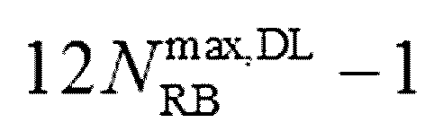 이고,
이고,  은 최대 RB의 개수이다. 의사 난수 시퀀스 생성기는 각 서브프레임의 시작에서
  로 초기화될 수 있다. ns는 무선 프레임 내 슬롯 번호,
  는 해당되는 EPDCCH 영역과 관련된 셀 인덱스,
  는 상위 계층 시그널링으로부터 주어지는 파라미터이다.
각 EPDCCH 영역(820, 830)은 서로 다른 셀을 위한 스케줄링에 사용될 수 있다. 예를 들어, EPDCCH 영역(820)내의 EPDCCH는 1차 셀을 위한 스케줄링 정보를 나르고, EPDCCH 영역(830)내의 EPDCCH는 2차 셀을 위한 스케줄링 정보를 나를 수 있다.
EPDCCH 영역(820, 830)에서 EPDCCH가 다중 안테나를 통해 전송될 때, EPDCCH 영역(820, 830)내의 DM-RS는 EPDCCH와 동일한 프리코딩이 적용될 수 있다.
PDCCH가 전송 자원 단위로 CCE를 사용하는 것과 비교하여, EPDCCH를 위한 전송 자원 단위를 ECCE(Enhanced Control Channel Element)라 한다. 집합 레벨(aggregation level)은 EPDCCH를 모니터링하는 자원 단위로 정의될 수 있다. 예를 들어, 1 ECCE가 EPDCCH를 위한 최소 자원이라고 할 때, 집합 레벨 L={1, 2, 4, 8, 16}과 같이 정의될 수 있다.
이하에서 탐색 영역(search space)은 EPDCCH 영역에 대응될 수 있다. 탐색 영역에서는 하나 또는 그 이상의 집합 레벨마다 하나 또는 그 이상의 EPDCCH 후보가 모니터링될 수 있다.
도 9는 LVRB 및 DVRB를 기반으로 VRB-PRB 매핑을 수행하는 방법을 나타낸 개념도이다.
도 9의 (A)는 VRB가 LVRB인 경우를 나타낸다. VRB가 LVRB인 경우, VRB를 바로 PRB의 위치로 매핑할 수 있다. 즉, 국소 타입(localized type)의 VRB는 동일한 위치의 PRB와 매핑될 수 있다.
도 9의 (B)는 VRB가 DVRB인 경우를 나타낸다. VRB가 DVRB인 경우, VRB는 RB 페어 인터리빙 및 RB 분산을 통해 PRB로 매핑될 수 있다. 이러한 경우 연속적인 VRB가 주파수 축 상에서 연속적인 PRB로 매핑되지 않을 수 있다. 분산 타입의 VRB는 시스템 대역폭을 기반으로 주파수 축 상에서 분산된 위치의 PRB와 매핑될 수 있다.
LTE Release 8/9/10 시스템 이후의 차기 시스템에서는 NCT(new carrier type) 서브프레임 또는 확장 캐리어(extension carrier) 서브프레임이 정의되어 새롭게 정의된 서브프레임을 통해 하향 링크 데이터 및 상향 링크 데이터를 송신 및 수신할 수 있다. NCT 서브프레임은 스몰 셀(small cell) 또는 마크로 셀(macro cell)과 같은 작은 셀 단위에서 최적화되어 구현된 캐리어 타입이 될 수 있다. NCT 서브프레임은 기존의 레가시 서브프레임에서 문제가 되는 참조 신호로 인한 오버헤드를 줄일 수 있다.
NCT 서브프레임은 기존의 시스템에서 전송되던 신호 및 채널을 통해 전송되던 정보 중 전부 또는 일부가 전송되지 않는 서브프레임이 될 수 있다. 예를 들어, NCT 서브프레임은 PDCCH 데이터 및 CRS와 같은 정보를 포함하지 않을 수 있다. NCT 서브프레임에서는 DCI와 같은 하향링크 제어 정보는 EPDDCH와 같은 채널을 통해 전송될 수 있다. NCT 서브프레임을 사용함으로서 복수의 셀 간의 간섭(interference) 문제를 개선하고 캐리어의 확장성을 향상시킬 수 있다.
이하, 본 발명의 실시예에서는 NCT 서브프레임에서 새롭게 정의된 DCI 포맷 1A 및 DCI 포맷 1에 대해 개시한다.
DCI 포맷 1A는 하향링크 RB 할당 방법에 대한 정보를 포함할 수 있다. DCI 포맷 1A는 다른 DCI 데이터 포맷과 달리 랜덤 액세스 절차를 위해 사용되는 데이터 포맷일 수 있다. 구체적으로 기존의 DCI 포맷 1A는 하향링크 RB 할당 방법으로 국부 할당 타입(localized allocation type)을 사용할지 분산 할당 타입(distributed allocation type)을 사용할지 여부에 대한 정보에 대한 지시 비트(indication bit)를 포함할 수 있다. 지시 비트는 VRB로 DVRB(distributed virtual resource block)를 사용할지 LVRB(localized virtual resource block)를 사용할지 여부에 대한 정보를 포함할 수 있다. 이러한 지시 비트를 다른 용어로 LVRB/DVRB 필드 또는 LVRB/DVRB 할당 플래그 또는 할당 플래그라고 할 수도 있다. 즉, 단말은 LVRB/DVRB 할당 플래그를 기반으로 VRB(virtual resource block)가 국소 타입(localized type)인지, 분산 타입(distributed type)인지 여부에 대한 정보를 획득할 수 있다.
전송 방법 중 DCI 포맷 1A를 사용하는 경우, 하향링크 서브프레임의 종류에 따라 PDSCH 데이터를 전송하는 안테나 포트를 서로 다르게 결정할 수 있다. 예를 들어, non-MBSFN(Multicast-Broadcast Single Frequency Network) 서브프레임은 PBCH 데이터를 전송하는 안테나 포트에 따라 PDSCH 데이터를 전송하는 안테나 포트를 결정할 수 있다. 기지국이 PBCH 데이터를 포트 0의 단일 안테나 포트(single antenna port)를 기반으로 전송하는 경우, PDSCH 데이터도 포트 0의 단일 안테나 포트(single antenna port)를 기반으로 전송할 수 있다. 또 다른 예로, 기지국이 non-MBSFN() 서브프레임에서 PBCH 데이터를 전송 다이버시티(transmit diversity)를 기반으로 전송할 수 있다. PDSCH 데이터도 전송 다이버시티를 기반으로 전송할 수 있다.
무선 프레임에 포함되는 복수의 서브프레임은 RRC(radio resource control) 메시지에 의해 MBSFN 서브프레임 또는 non-MBSFN 서브프레임으로 설정될 수 있다. 이하에서 MBSFN 서브프레임은 기지국에 의해 설정되는 특정 서브프레임을 의미한다.
기지국은 MBSFN 서브프레임에서 PDSCH 데이터를 포트 7의 단일 안테나 포트를 기반으로 전송할 수 있다. 기지국에서 포트 7을 기반으로 전송한 PDSCH 데이터는 URS를 기반으로 디모듈레이션을 수행할 수 있다. 단말이 URS를 기반으로 PDSCH 데이터를 디모듈레이션하는 경우, 단말은 URS를 기반으로 PDSCH 데이터를 디모듈레이션할 수 있다.
전술한 바와 같이 DVRB(distributed virtual resource block)는 서브프레임에서 동일한 주파수 대역에 할당되는 VRB(virtual resource block)를 PRB(physical resource block)로 매핑 시 주파수 축 상에서 서로 다른 주파수 대역으로 할당하는 방법이다. DVRB를 사용하는 경우는 주파수 대역이 분산이 되므로 URS를 기반으로 PDSCH 데이터를 디모듈레이션하는데 어려움이 있을 수 있다. 따라서, 단말이 URS를 사용하여 PDSCH 데이터에 대한 디모듈레이션을 수행할 경우, 자원 할당 방법으로 DVRB 자원 할당을 지원하지 않고 대신 LVRB 자원 할당을 지원할 수 있다.
CRS가 매 서브프레임마다 전송되는 기존의 레가시 서브프레임과 다르게 NCT 서브프레임은 특정한 주기(예를 들어, 5ms)를 기반으로 CRS를 전송할 수 있다. 상기 CRS는 NCT 서브프레임에서 전송되는 참조 신호를 특정하기 위한 하나의 예시적인 명칭이다. 상기 CRS는 다른 명칭, 예를 들어, TRS(tracking reference signal)이라고 할 수도 있다. NCT 서브프레임에서 전송되는 CRS는 주로 시간/주파수 트래킹을 수행하는 용도로 사용될 수 있다. NCT 서브프레임에서 특정한 주기로 전송되는 CRS는 PDSCH 데이터를 디모듈레이션하는 용도로 사용되지 않을 수도 있다.
. 즉, NCT 서브프레임에서는 URS를 기반으로 디모듈레이션을 수행할 수 밖에 없기 때문에 NCT 서브프레임은 MBSFN 서브프레임인지 non-MBSFN 서브프레임인지 여부에 상관이 없이 자원 할당 방법으로 LVRB만을 사용할 수 있다. NCT 서브프레임에서 자원 할당 방법으로 LVRB만을 사용하는 경우, DCI 포맷 1A에 포함된 자원 할당 타입에 대한 정보인 LVRB/DVRB 필드는 필요가 없다. 따라서, 기존의 DCI 포맷 1A의 LVRB/DVRB 필드를 다른 정보를 전송하기 위한 목적으로 사용할 수 있다. LVRB/DVRB 필드는 예를 들어, 아래와 같은 정보를 전송하기 위한 용도로 사용할 수 있다. 예를 들어, 서브프레임이 NCT 서브프레임인 경우, 단말은 LVRB/DVRB 필드(할당 플래그)를 아래와 같은 정보로 해석하여 수신된 데이터에 대한 디모듈레이션을 수행할 수 있다. 할당 플래그는 1비트의 비트값을 가질 수 있다.
(1) 스크램블링 식별자 시그널링(scrambling identity signaling)
LVRB/DVRB 필드를 URS의 슈도 랜덤 시퀀스(pseudo-random sequence)의 초기화에 사용하는 스크램블링 식별자(scrambling identity)의 값을 전송하는 용도로 사용할 수 있다.
스크램블링 식별자는 MU(multi-user)-MIMO(multiple-input multiple-output)를 지원하기 위한 참조 신호의 직교성(othogonality)를 확보하기 위한 정보일 수 있다. 즉, 전술한  에서
에서  의 값을 LVRB/DVRB 필드(할당 플래그)를 기반으로 전송할 수 있다.
(2) PDSCH 전송 안테나 포트 정보(PDSCH transmission antenna port information)
LVRB/DVRB 필드에 PDSCH을 전송하는 안테나 포트 정보를 포함하여 전송할 수 있다. 예를 들어, LVRB/DVRB 필드의 값이 0이면 안테나 포트 정보를 7, LVRB/DVRB 필드의 값이 1이면 안테나 포트 정보를 8로 지시할 수 있다. LVRB/DVRB 필드를 PDSCH 전송 안테나 포트 정보를 위해 사용하는 경우, 스크램블링 식별자는 0 또는 1로 고정하여 사용할 수 있다.
단말은 LVRB/DVRB 필드를 포함하는 DCI를 수신한 후 아래와 같은 동작을 수행할 수 있다. 단말은 DM-RS를 기반으로 DCI 포맷 1A의 DCI의 복조 여부를 판단할 수 있다. DM-RS를 기반으로 DCI 포맷 1A의 DCI이 복조되는 경우, DCI 포맷 1A를 NCT 서브프레임에 포함된 제어 데이터로 판단할 수 있다. DM-RS를 기반으로 DCI 포맷 1A의 DCI이 복조되지 않는 경우, DCI 포맷 1A를 레가시 서브프레임에 포함된 제어 데이터로 판단할 수 있다. 단말이 DM-RS를 기반으로 DCI 포맷 1A의 DCI를 복조하는 경우, LVRB/DVRB 필드를 기반으로 스크램블링 식별자 정보 또는 PDSCH(physical downlink shared channel) 전송 안테나 포트 정보를 획득할 수 있다. 단말이 CRS를 기반으로 DCI 포맷 1A의 DCI를 복조하는 경우, LVRB/DVRB 필드를 기반으로 VRB(virtual resource block)가 국소 타입(localized type)인지, 분산 타입(distributed type)인지 여부에 대한 정보를 획득할 수 있다.
또 다른 실시예로 NCT 서브프레임에서도 DVRB 자원 할당을 사용할 수 있다.
서브프레임에서 동일한 주파수 대역에 할당되는 두 슬롯의 VRB를 PRB로 매핑 시 매핑되는 PRB의 주파수 대역이 동일한 대역이 되도록 할당할 수 있다. 예를 들어, 첫 번째 슬롯에서 수행된 VRB를 PRB로 매핑하는 방법이 두 번째 슬롯에서도 동일하게 수행될 수 있다. 즉, DVRB에서 슬롯 호핑을 수행하지 않고 RB의 분배를 수행할 수 있다. NCT 서브프레임에서도 DVRB 자원 할당을 사용하는 경우에는 스크램블링 식별자 및 PDSCH 전송 안테나 포트 정보를 전송하기 위한 비트로 1bit 또는 2bit를 추가로 사용할 수 있다.
MU-MIMO 전송을 지원하기 위해 DCI 포맷 1A에 MU-MIMO 전송을 하기 위한 추가적인 비트를 포함할 수 있다. DCI 포맷 1A의 기존 시그널링 정보에 추가적으로 스클램블링 식별자 및 안테나 포트에 관한 시그널링 정보 또는 스클램블링 식별자 및 안테나 포트 정보에 대한 조합 정보를 1 비트 또는 2비트 추가하여 전송할 수 있다. 전술한 바와 같이 NCT 서브프레임이 MBSFN 서브프레임인지 non-MBSFN 서브프레임인지 여부에 상관이 없이 자원 할당 방법으로 LVRB를 사용하는 경우 DCI 포맷 1A에 포함된 자원 할당 타입에 대한 정보를 포함하는 LVRB/DVRB 필드는 필요가 없다. 따라서, LVRB/DVRB 필드를 추가적으로 스클램블링 식별자 및 안테나 포트에 관한 시그널링 정보 또는 스클램블링 식별자 및 안테나 포트 정보에 대한 조합 정보를 전송하기 위해 사용할 수도 있다.
이하, 본 발명의 실시예에서는 NCT 서브프레임에서 정의된 DCI 포맷 1에서 MU-MIMO를 지원하는 방법에 대해 개시한다.
DCI 포맷 1은 단일 안테나 포트 0 또는 단일 안테나 포트 7을 기반으로 한 단일 안테나 포트 전송 또는 전송 다이버시티와 같은 하향링크 PDSCH 전송을 수행하기 위해 사용될 수 있다.
단일 안테나 포트 0을 기반으로 한 하향링크 PDSCH 데이터 전송은 CRS(cell-specific reference signal)을 기반으로 디모듈레이션을 수행할 수 있다.
단일 안테나 포트 7을 기반으로 한 하향링크 PDSCH 데이터 전송은 안테나 포트 7를 기반으로 전송되는 URS(UE-specific reference signal)를 기반으로 디모듈레이션을 수행할 수 있다.
NCT 서브프레임에서는 DCI 포맷 1을 기반으로 MU-MIMO를 지원할 수 있다. NCT 서브프레임이 MBSFN 서브프레임인지 non-MBSFN 서브프레임인지 여부에 상관이 없이 자원 할당 방법으로 LVRB를 사용하는 경우 DCI 포맷 1에 포함된 자원 할당 타입에 대한 정보를 포함하는 LVRB/DVRB 필드는 필요가 없다. LVRB/DVRB 필드는 스크램블링 식별자 시그널링 및 PDSCH 전송 안테나 포트 정보로 사용될 수 있다.
(1) 스크램블링 식별자 시그널링
NCT 서브프레임에서는 DCI 포맷 1을 기반으로 MU-MIMO를 지원하기 위해서는 참조 신호의 직교성을 확보하기 위하여 URS의 슈도 랜덤 시퀀스의 초기화에 사용되는 스크램블링 식별자의 값을 LVRB/DVRB 필드를 기반으로 시그널링할 수 있다.  에서
에서  의 값을 LVRB/DVRB 필드를 기반으로 전송할 수 있다.
(2) PDSCH 전송 안테나 포트 정보
DCI 포맷 1을 기반으로 MU-MIMO를 지원하기 위한 방법으로 PDSCH를 전송하는데 사용하는 안테나 포트 정보를 LVRB/DVRB 필드를 기반으로 전송할 수 있다. 예를 들어, DCI 포맷의 LVRB/DVRB 필드의 값이 0이면 기지국이 안테나 포트 7를 기반으로 PDSCH를 전송하는 것을 지시하고, LVRB/DVRB 필드의 값이 1이면 기지국이 안테나 포트 8을 기반으로 PDSCH를 전송하는 것을 지시할 수 있다. LVRB/DVRB 필드의 값을 PDSCH를 전송하는 안테나 포트 정보로 사용하면, 스크램블링 식별자는 0 또는 1의 고정된 값으로 사용할 수 있다.
DCI 포맷 1에서 최대 4개의 단말을 대상으로 MU-MIMO를 지원하기 위해 기존의 시그널링 비트에 추가적인 1비트 또는 2비트를 추가하여 전송을 수행할 수 있다. 추가적인 1비트 또는 2비트는 추가적인 단말에 대한 전송을 수행하기 위한 스크램블링 식별자 정보 및 PDSCH 전송 안테나 정보를 전송하기 위해 사용할 수 있다. NCT 서브프레임은 아래와 같은 전송 모드 및 전송 모드에 따른 DCI 포맷을 가질 수 있다.
(1) 전송 모드 x1
-전송 모드 x1은 모든 서브프레임 타임(MBSFN() 서브프레임 또는 non-MBSFN() 서브프레임)에서 기지국이 단일 안테나 포트 7을 통해 PDSCH을 전송하는 전송 방법일 수 있다. 기지국이 전송 모드 x1로 데이터를 단말로 전송할 경우 DCI 포맷 1A를 기반으로 제어 데이터를 단말로 전송할 수 있다.
-전송 모드 x1은 MU-MIMO를 지원하는 한 전송 방법일 수도 있다. 기지국은 전송을 수행시 8개의 레이어까지 PDSCH를 단말로 전송할 수 있다. 기지국은 기존의 레가시 DCI 포맷 2C를 이용하여 제어 데이터를 단말로 전송할 수 있다.
(2) 전송 모드 x2
-전송 모드 x2는 기지국이 단일 안테나 포트 7을 통해 PDSCH를 전송하는 전송 방법일 수 있다. 기지국이 전송 모드 x2로 데이터를 단말로 전송할 경우 DCI 포맷 1A를 기반으로 제어 데이터를 단말로 전송할 수 있다. DCI 포맷 1A는 LVRB/DVRB 필드에 스크램블링 식별자 정보를 포함할 수 있다.
- 전송 모드 x2는 MU-MIMO를 지원하는 한 전송 방법일 수도 있다. 기지국이 단말로 데이터 전송을 수행 시 8개의 레이어까지 PDSCH 데이터를 단말로 전송할 수 있다. 기지국은 기존의 레가시 DCI 포맷 2C를 기반으로 제어 데이터를 단말로 전송할 수 있다.
(3) 전송 모드 x3
-전송 모드 x3는 기지국이 단일 안테나 포트를 기반으로 PDSCH를 단말로 전송하는 전송 방법일 수 있다. 전송 모드 x3를 사용할 경우 기지국은 DCI 포맷 1A를 기반으로 제어 정보를 단말로 전송할 수 있다. DCI 포맷 1A의 LVRB/DVRB 필드는 안테나 포트 정보를 전송하기 위한 정보일 수 있다.
-전송 모드 x3는 MU-MIMO를 지원하는 한 전송 방법일 수도 있다. 기지국이 전송을 수행시 8개의 레이어까지 PDSCH 데이터를 단말로 전송할 수 있다. 기지국은 기존의 레가시 DCI 포맷 2C를 이용하여 제어 정보를 단말로 전송할 수 있다.
(4) 전송 모드 x4
-전송 모드 x4는 기지국이 단일 안테나 포트를 통해 PDSCH를 단말로 전송하는 전송 방법일 수 있다. 전송 모드 x4를 사용할 경우, 기지국은 DCI 포맷 1A를 기반으로 제어 정보를 단말로 전송할 수 있다. DCI 포맷 1A은 기존의 DCI 포맷 1A에 1비트 또는 2비트가 추가된 형태의 DCI 포맷 1A일 수 있다. 추가된 1비트 또는 2비트를 통해 스클램블링 식별자 및 안테나 포트 정보를 전송할 수 있다.
-전송 모드 x4는 MU-MIMO를 지원하는 한 전송 방법일 수도 있다. 기지국이 단말로 전송을 수행시 기지국은 8개의 레이어까지 단말로 PDSCH 데이터를 전송할 수 있다. 기지국은 기존의 레가시 DCI 포맷 2C를 제어 데이터를 단말로 전송할 수 있다.
(5) 전송 모드 y1
-전송 모드 y1은 모든 서브프레임 타임(MBSFN 서브프레임 또는 non-MBSFN 서브프레임)에 대하여 기지국이 단일 안테나 포트 7을 통해 PDSCH 데이터를 단말로 전송하는 방법일 수 있다. 전송 모드 y1에서 기지국은 DCI 포맷 1A를 기반으로 제어 데이터를 단말로 전송할 수 있다.
-기지국은 단일 안테나 포트 7를 기반으로 PDSCH 데이터를 단말로 전송할 수 있다. 기지국은 DCI 포맷 1을 기반으로 제어 데이터를 단말로 전송할 수 있다. 스크램블링 식별자 정보를 전송하기 위해 기존의 DCI 포맷 1에 1 비트를 추가할 수 있다.
(6) 전송 모드 y2
-전송 모드 y2는 모든 서브프레임 타임(MBSFN() 서브프레임 또는 non-MBSFN() 서브프레임)에 대하여 기지국이 단일 안테나 포트 7을 통해 PDSCH를 전송하는 방법일 수 있다. 기지국은 전송 모드 y2에서는 DCI 포맷 1A를 기반으로 제어 데이터를 단말로 전송할 수 있다.
-기지국은 단일 안테나 포트로 PDSCH를 전송하고 DCI 포맷 1을 기반으로 제어 데이터를 단말로 전송할 수 있다. 안테나 포트 정보를 전송하기 위해 기존의 DCI 포맷 1에 1비트를 추가할 수 있다.
(7) 전송 모드 y3
-전송 모드 y3는 모든 서브프레임 타임에 대하여 기지국이 단일 안테나 포트 7을 통해 PDSCH 데이터를 단말로 전송할 수 있다. 전송 모드 y3에서는 DCI 포맷 1A를 기반으로 제어 데이터를 단말로 전송할 수 있다.
-기지국은 단일 안테나 포트로 PDSCH 데이터를 단말로 전송하고 DCI 포맷 1을 기반으로 제어 데이터를 단말로 전송할 수 있다. 스크램블링 식별자 정보 및 안테나 포트 정보를 전송하기 위해 기존의 DCI 포맷 1에 2비트를 추가할 수 있다.
(8) 전송 모드 y4
-전송 모드 y4는 모든 서브프레임 타임에 대하여 기지국이 단일 안테나 포트 7을 통해 PDSCH 데이터를 단말로 전송할 수 있다. 전송 모드 y4에서는 DCI 포맷 1A를 기반으로 제어 데이터를 단말로 전송할 수 있다.
-기지국은 단일 안테나 포트 7로 PDSCH 데이터를 전송할 수 있다. 기지국은 DCI 포맷 1을 기반으로 제어 데이터를 단말로 전송할 수 있다.
전술한 (1) 내지 (8)의 전송 모드는 아래의 표 5와 같이 정리될 수 있다.
<표 5>


전술한 (1) 내지 (8)의 전송 모드 중 적어도 하나의 모드가 NCT 서브프레임의 전송 모드로서 사용될 수 있다. 즉, 표 5에 개시된 복수의 전송 모드 중 적어도 하나의 전송 모드를 NCT 서브프레임의 전송 모드로 사용할 수 있고 이러한 실시예 또한 본 발명의 권리 범위에 포함된다.
본 발명의 또 다른 실시예에 따르면 단말은 PDSCH 데이터를 디모듈레이션하기 위해 ePDCCH를 디모듈레이션하기 위해 사용한 참조 신호의 안테나 포트 정보를 사용할 수 있다.
도 10은 본 발명의 실시예에 따른 EPDCCH를 기반으로 PDSCH를 디모듈레이션하는 방법을 나타낸 개념도이다.
기지국은 제어 데이터를 전송하기 위해 채널로 PDCCH뿐만 아니라 EPDCCH를 사용할 수도 있다. EPDCCH는 DM-RS를 기반으로 디모듈레이션을 수행할 수 있다. PDSCH 데이터를 디모듈레이션함에 있어서 사용하는 안테나 포트 정보를 EPDCCH를 디모듈레이션하기 위한 DM-RS의 안테나 포트 정보로부터 획득할 수 있다. 예를 들어, 기지국이 랭크 1의 PDSCH 데이터 전송을 수행하는 경우를 가정한다. 이러한 경우, EPDCCH 데이터(1000)의 전송을 위해서 사용하는 DM-RS의 안테나 포트 번호가 7인 경우, PDSCH의 안테나 포트 번호 또한 7이라고 가정하여 PDSCH 데이터(1020)에 대한 디모듈레이션을 수행할 수 있다. 또한, EPDCCH 데이터(1040)의 전송을 위해서 사용하는 DM-RS의 안테나 포트 번호가 8인 경우, PDSCH의 안테나 포트 번호 또한 8이라고 가정하여 PDSCH 데이터(1060)에 대한 디모듈레이션을 수행할 수 있다. 이는 하나의 예이고, 소정의 매핑 관계를 기반으로 DM-RS의 안테나 포트 번호를 기반으로 PDSCH의 안테나 포트 번호를 유추할 수도 있다.
유사한 방법으로 EPDCCH를 검출하기 위해 사용한 파라메터를 PDSCH를 디모듈레이션하기 위한 파라메터로 사용할 수도 있다. 예를 들어, DM-RS의 슈도 랜덤 시퀀스의 초기값을 결정하기 위한 가상 셀 아이디 및 스크램블링 셀 아이디 값 등이 PDSCH 데이터를 디모듈레이션하기 위한 URS의 슈도 랜덤 시퀀스의 초기값을 결정하기 위한 파라메터로 사용될 수 있다.
도 11은 본 발명의 실시예에 따른 EPDCCH를 기반으로 PDSCH를 디모듈레이션하는 방법을 나타낸 개념도이다.
도 11을 참조하면, 두 개의 단말(예를 들어, 제1 단말, 제2 단말)이 EPDCCH를 기반으로 동일한 PDSCH 영역으로 스케쥴링된 경우를 가정할 수 있다. 이러한 경우, 제1 단말 및 제2 단말이 EPDCCH 데이터를 수신하기 위한 참조 신호의 안테나 포트 정보 또는 스크램블링 식별자 정보를 서로 다른 값일 수 있다.
예를 들어, 제1 단말이 EPDCCH 데이터(1100)를 수신하기 위한 참조 신호의 안테나 포트 번호가 7인 경우, 제2 단말이 EPDCCH 데이터(1120)를 수신하기 위한 참조 신호의 안테나 포트 번호가 8일 수 있다. 서로 다른 안테나 포트 정보를 기반으로 동일한 영역에 스케쥴링된 PDSCH 데이터(1140)를 디모듈레이션하여 단말이 PDSCH 데이터(1140)를 획득할 수 있다. 예를 들어, 제1 단말은 안테나 포트 번호 7을 기반으로 동일한 영역에 스케쥴링된 PDSCH 데이터(1140)를 디모듈레이션할 수 있고 제2 단말은 안테나 포트 번호 8을 기반으로 동일한 영역에 스케쥴링된 PDSCH 데이터(1140)를 디모듈레이션할 수 있다. 안테나 포트가 아닌 다른 스크램블링 식별자 정보를 기반으로 동일한 영역에 스케쥴링된 PDSCH 데이터를 각 단말이 디모듈레이션할 수 있다.
도 12는 본 발명의 실시예에 따른 EPDCCH를 기반으로 PDSCH를 디모듈레이션하는 방법을 나타낸 개념도이다.
도 12에서는 기지국이 복수의 안테나 포트 정보를 기반으로 EPDCCH 데이터를 생성한 경우를 가정할 수 있다. EPDCCH을 전송하기 위한 안테나 포트의 집합이 PDSCH를 전송하기 위한 안테나 포트 집합보다 큰 집합일 수도 있다. 예를 들어, PRB 페어(physical resource block pair)에서 4개의 EPDCCH 데이터(1200, 1210, 1220, 1230)를 전송하는 경우를 가정할 수 있다. PRB 페어에서 4개의 EPDCCH 데이터(1200, 1210, 1220, 1230)를 전송하는 경우, EPDCCH에 직교하는 4개의 안테나 포트가 할당되어야 한다. 예를 들어, 직교하는 4개의 안테나 포트의 안테나 포트 번호는 7, 8, 9, 10일 수 있다.
DCI 포맷 1A가 랭크 1의 PDSCH 데이터 전송만을 수행한다고 가정하면, URS의 오버헤드를 변동시키지 않기 위해 PDSCH 데이터를 전송하기 위한 안테나 포트를 7 또는 8로 제한할 수 있다.
이러한 경우, EPDCCH을 전송하기 위한 안테나 포트와 PDSCH을 전송하기 위한 안테나 포트 사이에는 일련의 관계가 존재할 수 있다. 예를 들어, EPDCCH 데이터를 전송하기 위한 안테나 포트가 7(1200) 또는 9(1220)인 경우, PDSCH 데이터(1240)를 전송하기 위한 안테나 포트를 7로 가정하여 PDSCH 데이터(1240)에 대한 디모듈레이션을 수행할 수 있다. EPDCCH 데이터를 전송하기 위한 안테나 포트가 8(1210) 또는 10(1230)인 경우, PDSCH 데이터를 전송하기 위한 안테나 포트를 8로 가정하여 PDSCH 데이터(1250)에 대한 디모듈레이션을 수행할 수 있다.
도 13은 본 발명의 실시예에 따른 EPDCCH를 기반으로 PDSCH를 디모듈레이션하는 방법을 나타낸 개념도이다.
도 13에서는 기지국이 복수의 안테나 포트 정보를 기반으로 EPDCCH 데이터를 생성한 경우를 가정할 수 있다.
EPDCCH를 전송하기 위해 사용하는 복수의 안테나 포트가 사용될 수도 있다. 예를 들어, EPDCCH를 전송하기 위해 두 개의 CCE(1300, 1310)가 사용될 수 있다. 두 개의 CCE(1300, 1310)는 서로 다른 안테나 포트 정보를 기반으로 전송될 수 있다. 기지국이 EPDCCH 데이터를 DCI 포맷 1A를 기반으로 단말로 전송한다고 가정할 수 있다. DCI 포맷 1A를 기반으로 전송되는 EPDCCH는 두 개의 CCE(1300, 1310)를 통해 전송될 수 있다. 두 개의 CCE가 서로 다른 PRB 페어에 위치한다고 가정하는 경우, DCI 포맷 1A를 기반으로 전송되는 EPDCCH는 서로 다른 안테나 포트를 통해 전송될 수 있다. 예를 들어, 제1 CCE(1300)는 안테나 포트 7을 통해 전송되고, 제2 CCE(1310)는 안테나 포트 8을 통해 전송될 수 있다. 이러한 경우 안테나 포트 7 또는 안테나 포트 8 중 하나의 안테나 포트를 PDSCH 데이터(1350)를 전송한 안테나 포트로 결정하여 PDSCH 데이터(1350)에 대한 디모듈레이션을 수행할 수 있다. 예를 들어, CCE 인덱스 중 작은 CCE 인덱스를 전송하기 위해 사용한 안테나 포트 정보를 PDSCH 데이터(1350)를 전송한 안테나 포트로 결정할 수 있다. CCE 인덱스 중 작은 CCE 인덱스를 전송하기 위해 사용한 안테나 포트 정보인 안테나 포트 7이 PDSCH 데이터(1350)를 디모듈레이션하기 위한 안테나 포트 정보일 수 있다.
본 발명의 실시예에 따르면, 도 10 내지 도 13은 단말이 LVRB/DVRB 필드를 기반으로 스크램블링 식별자 정보를 획득하는 경우, DM-RS를 전송하는 안테나 포트 정보로부터 상기 PDSCH 전송 안테나 포트 정보를 유도하는 방법으로 사용할 수 있다. 즉, 단말은 DM-RS를 전송하는 안테나 포트 번호와 PDSCH 전송 안테나 포트 번호 사이에 미리 결정된 매핑 관계를 기반으로 DM-RS를 전송하는 안테나 포트 번호로부터 PDSCH 전송 안테나 포트 번호를 유도할 수 있다. 또 다른 예로 DM-RS를 전송하는데 사용한 복수의 안테나 포트 번호를 기반으로 PDSCH 전송 안테나 포트 정보를 획득할 수 있다.
도 14는 본 발명의 실시예에 따른 무선통신 시스템을 나타낸 블록도이다.
도 14를 참조하면, 기지국(1400)은 프로세서(processor, 1210), 메모리(memory, 1420) 및 RF부(RF(radio frequency) unit, 1430)을 포함한다. 메모리(1420)는 프로세서(1410)와 연결되어, 프로세서(1410)를 구동하기 위한 다양한 정보를 저장한다. RF부(1420)는 프로세서(1410)와 연결되어, 무선 신호를 송신 및/또는 수신한다. 프로세서(1410)는 제안된 기능, 과정 및/또는 방법을 구현한다. 전술한 실시예에서 기지국의 동작은 프로세서(1410)에 의해 구현될 수 있다.
예를 들어, 프로세서(1410)는 생성 프레임이 레가시 서브프레임인지 NCT 서브프레임인지 여부에 따라 할당 플래그가 PDSCH 데이터의 복조에 사용되는 RS에 관한 정보 또는 상기 PDSCH의 전송 안테나 포트에 관한 정보를 지시하거나 PDSCH를 위한 LVRB 할당 또는 DVRB 할당을 지시하도록 구현될 수 있다. PDSCH 데이터의 복조에 사용되는 RS에 관한 정보는 RS를 생성하는데 사용되는 슈도 랜덤 시퀀스의 초기화에 사용되는 스크램블링 식별자의 값일 수 있다.
무선기기(1450)는 프로세서(1460), 메모리(1470) 및 RF부(1480)을 포함한다. 무선기기(1450)는 다른 용어로 단말이라고 할 수 있다. 메모리(1470)는 프로세서(1460)와 연결되어, 프로세서(1460)를 구동하기 위한 다양한 정보를 저장한다. RF부(1480)는 프로세서(1460)와 연결되어, 무선 신호를 송신 및/또는 수신한다. 프로세서(1460)는 제안된 기능, 과정 및/또는 방법을 구현한다. 전술한 실시예에서 무선기기의 동작은 프로세서(1460)에 의해 구현될 수 있다.
예를 들어, 프로세서(1460)는 할당 플래그 및 DL(downlink) 자원 할당을 포함하는 DCI를 복조하고 DL 자원 할당을 이용하여 PDSCH 데이터를 복조하도록 구현될 수 있다.
무선기기(1450)은 DM-RS를 기반으로 DCI가 복조되는 경우, 할당 플래그는 PDSCH 데이터의 복조에 사용되는 RS에 관한 정보 또는 PDSCH의 전송 안테나 포트에 관한 정보를 지시하는 것으로 판단할 수 있다. 무선기기(1450)은 셀 특정적인 RS를 기반으로 DCI가 복조되면, 할당 플래그는 PDSCH를 위한 LVRB 할당 또는 DVRB 할당을 지시하는 것으로 판단할 수 있다.
프로세서는 ASIC(application-specific integrated circuit), 다른 칩셋, 논리 회로 및/또는 데이터 처리 장치를 포함할 수 있다. 메모리는 ROM(read-only memory), RAM(random access memory), 플래쉬 메모리, 메모리 카드, 저장 매체 및/또는 다른 저장 장치를 포함할 수 있다. RF부는 무선 신호를 처리하기 위한 베이스밴드 회로를 포함할 수 있다. 실시예가 소프트웨어로 구현될 때, 상술한 기법은 상술한 기능을 수행하는 모듈(과정, 기능 등)로 구현될 수 있다. 모듈은 메모리에 저장되고, 프로세서에 의해 실행될 수 있다. 메모리는 프로세서 내부 또는 외부에 있을 수 있고, 잘 알려진 다양한 수단으로 프로세서와 연결될 수 있다.
상술한 예시적인 시스템에서, 방법들은 일련의 단계 또는 블록으로써 순서도를 기초로 설명되고 있지만, 본 발명은 단계들의 순서에 한정되는 것은 아니며, 어떤 단계는 상술한 바와 다른 단계와 다른 순서로 또는 동시에 발생할 수 있다. 또한, 당업자라면 순서도에 나타낸 단계들이 배타적이지 않고, 다른 단계가 포함되거나 순서도의 하나 또는 그 이상의 단계가 본 발명의 범위에 영향을 미치지 않고 삭제될 수 있음을 이해할 수 있을 것이다.
Claims (14)
- 단말의 제어 데이터 수신 방법에 있어서,
할당 플래그 및 DL(downlink) 자원 할당을 포함하는 DCI(downlink control information)를 복조하는 단계; 및
상기 DL 자원 할당을 이용하여 PDSCH(physical downlink shared channel) 데이터를 복조하는 단계를 포함하되,
상기 PDSCH 데이터가 DM-RS(demodulation reference signal)를 기반으로 복조되면, 상기 할당 플래그는 상기 PDSCH 데이터의 복조에 사용되는 RS(reference signal)에 관한 정보 또는 상기 PDSCH의 전송 안테나 포트에 관한 정보를 지시하고,
상기 PDSCH 데이터가 셀 특정적인 RS를 기반으로 복조되면, 상기 할당 플래그는 PDSCH를 위한 LVRB(localized virtual resource block) 할당 또는 DVRB(distributed virtual resource block) 할당을 지시하고,
상기 LVRB 할당은 주파수 영역 상에서 동일한 위치의 적어도 하나의 PRB(physical resource block)를 지시하고,
상기 DVRB 할당은 주파수 영역 상에서 분산된 위치의 적어도 하나의 PRB를 지시하고,
상기 할당 플래그는 1비트이고,
상기 DM-RS는 스크램블 식별자에 의해 초기화되는 슈도 랜덤 시퀀스로부터 생성되고,
상기 스크램블 식별자는 기지국에 의해 주어지고,
상기 셀 특정적인 RS는 셀 식별자에 의해 초기화되는 슈도 랜덤 시퀀스로부터 생성되는 제어 데이터 수신 방법. - 제1항에 있어서,
상기 할당 플래그를 기반으로 상기 PDSCH의 전송 안테나 포트 정보를 획득하는 경우, 상기 스크램블링 식별자 정보는 0 또는 1의 값을 가지는 제어 데이터 수신 방법. - 제1항에 있어서,
상기 할당 플래그를 기반으로 스크램블링 식별자 정보를 획득하는 경우, 상기 DM-RS를 전송하는 안테나 포트 정보로부터 상기 PDSCH 전송 안테나 포트 정보를 유도하는 단계를 더 포함하는 제어 데이터 수신 방법. - 제3항에 있어서, 상기 PDSCH 전송 안테나 포트 정보는,
상기 DM-RS를 전송하는 안테나 포트 번호와 상기 PDSCH 전송 안테나 포트 번호 사이에 미리 결정된 매핑 관계를 기반으로 유도되는 제어 데이터 수신 방법. - 제3항에 있어서, 상기 PDSCH 전송 안테나 포트 정보는,
상기 DM-RS가 복수의 안테나 포트 번호를 기반으로 생성된 경우, 상기 복수의 안테나 포트 번호 중 하나의 번호를 기반으로 유도되는 제어 데이터 수신 방법. - 제1항에 있어서, 상기 PDSCH 데이터의 복조에 사용되는 RS에 관한 정보는,
상기 RS를 생성하는데 사용되는 슈도 랜덤 시퀀스의 초기화에 사용되는 스크램블링 식별자의 값인 제어 데이터 수신 방법. - 제1항에 있어서,
상기 PDSCH 데이터가 상기 DM-RS를 기반으로 복조되는 경우 상기 DCI는 DM-RS를 기반으로 복조되고,
상기 PDSCH 데이터가 상기 셀 특정적인 RS를 기반으로 복조되는 경우 상기 DCI는 셀 특정적인 RS를 기반으로 복조되는 단말.
- 무선 통신 시스템에서 제어 데이터를 수신하는 단말에 있어서, 상기 단말은 프로세서를 포함하고,
상기 프로세서는 할당 플래그 및 DL(downlink) 자원 할당을 포함하는 DCI(downlink control information)를 복조하고 상기 DL 자원 할당을 이용하여 PDSCH(physical downlink shared channel) 데이터를 복조하도록 구현되되,
상기 PDSCH 데이터가 DM-RS(demodulation reference signal)를 기반으로 복조되면, 상기 할당 플래그는 상기 PDSCH 데이터의 복조에 사용되는 RS(reference signal)에 관한 정보 또는 상기 PDSCH의 전송 안테나 포트에 관한 정보를 지시하고,
상기 PDSCH 데이터가 셀 특정적인 RS를 기반으로 복조되면, 상기 할당 플래그는 PDSCH를 위한 LVRB(localized virtual resource block) 할당 또는 DVRB(distributed virtual resource block) 할당을 지시하고,
상기 LVRB 할당은 주파수 영역 상에서 동일한 위치의 적어도 하나의 PRB(physical resource block)를 지시하고,
상기 DVRB 할당은 주파수 영역 상에서 분산된 위치의 적어도 하나의 PRB를 지시하고,
상기 할당 플래그는 1비트이고,
상기 DM-RS는 특정 스크램블 식별자에 의해 초기화되는 슈도 랜덤 시퀀스로부터 생성되고,
상기 스크램블 식별자는 기지국에 의해 주어지고,
상기 셀 특정적인 RS는 셀 식별자에 의해 초기화되는 슈도 랜덤 시퀀스로부터 생성되는 단말.
제7항에 있어서, 상기 프로세서는,
상기 할당 플래그를 기반으로 상기 PDSCH의 전송 안테나 포트 정보를 획득하는 경우, 상기 스크램블링 식별자 정보가 0 또는 1의 값을 가지도록 구현되는 단말. - 제8항에 있어서, 상기 프로세서는,
상기 할당 플래그를 기반으로 상기 PDSCH의 전송 안테나 포트 정보를 획득하는 경우, 상기 스크램블링 식별자 정보가 0 또는 1의 값을 가지도록 구현되는 단말. - 제8항에 있어서, 상기 프로세서는,
상기 할당 플래그를 기반으로 스크램블링 식별자 정보를 획득하는 경우, 상기 DM-RS를 전송하는 안테나 포트 정보로부터 상기 PDSCH 전송 안테나 포트 정보를 유도하도록 구현되는 단말. - 제10항에 있어서, 상기 PDSCH 전송 안테나 포트 정보는,
상기 DM-RS를 전송하는 안테나 포트 번호와 상기 PDSCH 전송 안테나 포트 번호 사이에 미리 결정된 매핑 관계를 기반으로 유도되는 단말. - 제10항에 있어서, 상기 PDSCH 전송 안테나 포트 정보는,
상기 DM-RS가 복수의 안테나 포트 번호를 기반으로 생성된 경우, 상기 복수의 안테나 포트 번호 중 하나의 번호를 기반으로 유도되는 단말. - 제8항에 있어서, 상기 PDSCH 데이터의 복조에 사용되는 RS에 관한 정보는,
상기 RS를 생성하는데 사용되는 슈도 랜덤 시퀀스의 초기화에 사용되는 스크램블링 식별자의 값인 단말. - 제8항에 있어서,
상기 PDSCH 데이터가 상기 DM-RS를 기반으로 복조되는 경우 상기 DCI는 DM-RS를 기반으로 복조되고,
상기 PDSCH 데이터가 상기 셀 특정적인 RS를 기반으로 복조되는 경우 상기 DCI는 셀 특정적인 RS를 기반으로 복조되는 단말.
Priority Applications (1)
| Application Number | Priority Date | Filing Date | Title |
|---|---|---|---|
| US14/398,308 US9510338B2 (en) | 2012-05-03 | 2013-05-03 | Data transmission method and data transmission device |
Applications Claiming Priority (2)
| Application Number | Priority Date | Filing Date | Title |
|---|---|---|---|
| US201261642413P | 2012-05-03 | 2012-05-03 | |
| US61/642,413 | 2012-05-03 |
Publications (1)
| Publication Number | Publication Date |
|---|---|
| WO2013165206A1 true WO2013165206A1 (ko) | 2013-11-07 |
Family
ID=49514546
Family Applications (1)
| Application Number | Title | Priority Date | Filing Date |
|---|---|---|---|
| PCT/KR2013/003846 Ceased WO2013165206A1 (ko) | 2012-05-03 | 2013-05-03 | 데이터 전송 방법 및 장치 |
Country Status (2)
| Country | Link |
|---|---|
| US (1) | US9510338B2 (ko) |
| WO (1) | WO2013165206A1 (ko) |
Cited By (2)
| Publication number | Priority date | Publication date | Assignee | Title |
|---|---|---|---|---|
| US20180352540A1 (en) * | 2015-11-18 | 2018-12-06 | Lg Electronics Inc. | Methods for transmitting and receiving reference signals in wireless communication system, and devices for same |
| CN111278137A (zh) * | 2017-06-16 | 2020-06-12 | 华为技术有限公司 | 上行资源的授权方法、装置及系统 |
Families Citing this family (18)
| Publication number | Priority date | Publication date | Assignee | Title |
|---|---|---|---|---|
| US9166718B2 (en) * | 2012-05-11 | 2015-10-20 | Intel Corporation | Downlink control indication for a stand-alone new carrier type (NCT) |
| US9647818B2 (en) | 2013-01-03 | 2017-05-09 | Intel IP Corporation | Apparatus and method for single-tone device discovery in wireless communication networks |
| CN105103634B (zh) | 2013-03-29 | 2019-03-22 | 英特尔Ip公司 | 无线通信网络中的扩展型呼叫非连续接收(drx)周期 |
| HUE040329T2 (hu) * | 2013-04-04 | 2019-03-28 | Intel Ip Corp | Rádiókapcsolat figyelés EPDCCH-hoz |
| US9191178B2 (en) | 2013-04-04 | 2015-11-17 | Intel IP Corporation | Enhanced node B and method for RRC connection establishment for small data transfers |
| CN104350770B (zh) * | 2013-05-17 | 2019-04-16 | 华为技术有限公司 | 业务数据加扰方法、业务数据解扰方法、装置及系统 |
| US10334569B2 (en) | 2013-06-05 | 2019-06-25 | Texas Instruments Incorporated | NLOS wireless backhaul downlink communication |
| CN105052187B (zh) * | 2013-12-16 | 2020-03-20 | 华为技术有限公司 | 导频信号的传输方法、基站及用户设备 |
| CN104754744B (zh) * | 2013-12-30 | 2018-06-05 | 南京中兴软件有限责任公司 | Lte小区的资源分配方法、装置及基站 |
| CN104936183B (zh) * | 2014-03-17 | 2020-06-16 | 中兴通讯股份有限公司 | 一种传输数据的方法及装置 |
| EP3678439B1 (en) * | 2014-10-28 | 2021-12-01 | Sony Group Corporation | Communication apparatus and communication method |
| US10298372B2 (en) * | 2014-11-05 | 2019-05-21 | Intel IP Corporation | Enhanced physical downlink control channel in machine-type communication |
| EP3413647B1 (en) | 2016-02-03 | 2021-06-23 | Sony Corporation | Terminal device, base station device, and communication method |
| JP2020530212A (ja) * | 2017-06-15 | 2020-10-15 | 中▲興▼通▲訊▼股▲ふぇん▼有限公司Zte Corporation | シーケンス生成のための方法および装置 |
| CN109995499B (zh) | 2017-08-11 | 2020-04-03 | 华为技术有限公司 | 接收解调参考信号的方法、接收端、芯片、存储介质和通信系统 |
| US11356311B2 (en) * | 2018-01-12 | 2022-06-07 | Telefonaktiebolaget Lm Ericsson (Publ) | Scrambling of physical channels and reference signals in wireless communication networks |
| CN110351849B (zh) | 2018-04-04 | 2023-07-04 | 大唐移动通信设备有限公司 | 资源分配方法及装置、基站和终端 |
| EP3791690B1 (en) * | 2018-05-07 | 2024-07-03 | Mavenir Networks, Inc. | Method and apparatus for fronthaul compression in cloud ran |
Family Cites Families (1)
| Publication number | Priority date | Publication date | Assignee | Title |
|---|---|---|---|---|
| US9197387B2 (en) * | 2011-08-15 | 2015-11-24 | Google Technology Holdings LLC | Method and apparatus for control channel transmission and reception |
-
2013
- 2013-05-03 WO PCT/KR2013/003846 patent/WO2013165206A1/ko not_active Ceased
- 2013-05-03 US US14/398,308 patent/US9510338B2/en not_active Expired - Fee Related
Non-Patent Citations (5)
| Title |
|---|
| "3GPP; TSGRAN; E-UTRA; Physical layer procedures (Release 10)", 3GPP TS 36.213 V10.5.0, March 2012 (2012-03-01), pages 23 - 31 * |
| ETRI: "DM RS sequence setting for downlink CoMP", 3GPP TSG RAN WG1 #67, 14 November 2011 (2011-11-14), SAN FRANCISCO, USA, pages 1 - 3 * |
| LG ELECTRONICS: "Details of Reference Signals for E-PDCCH", RL-121453, 3GPP TSG RAN WG1 MEETING #68BIS, 26 March 2012 (2012-03-26), JEJU, KOREA, pages 1 - 5 * |
| NOKIA ET AL.: "Signaling ePDCCH presence using demodulation reference signals", RL-121286, 3GPP TSG RAN WG1 MEETING #68BIS, 26 March 2012 (2012-03-26), JEJU, KOREA, pages 1 - 4 * |
| PANASONIC: "DCI for Rel-11 CoMP Operations", 3GPP TSG RAN WG1 MEETING #68BIS, 26 March 2010 (2010-03-26), JEJU, KOREA, pages 1 - 2 * |
Cited By (5)
| Publication number | Priority date | Publication date | Assignee | Title |
|---|---|---|---|---|
| US20180352540A1 (en) * | 2015-11-18 | 2018-12-06 | Lg Electronics Inc. | Methods for transmitting and receiving reference signals in wireless communication system, and devices for same |
| US10667243B2 (en) * | 2015-11-18 | 2020-05-26 | Lg Electronics Inc. | Methods for transmitting and receiving reference signals in wireless communication system, and devices for same |
| CN111278137A (zh) * | 2017-06-16 | 2020-06-12 | 华为技术有限公司 | 上行资源的授权方法、装置及系统 |
| CN111278137B (zh) * | 2017-06-16 | 2021-01-05 | 华为技术有限公司 | 上行资源的授权方法、装置及系统 |
| US11252755B2 (en) | 2017-06-16 | 2022-02-15 | Huawei Technologies Co., Ltd. | Uplink resource grant methods and apparatus |
Also Published As
| Publication number | Publication date |
|---|---|
| US20150085785A1 (en) | 2015-03-26 |
| US9510338B2 (en) | 2016-11-29 |
Similar Documents
| Publication | Publication Date | Title |
|---|---|---|
| US10958397B2 (en) | Method and apparatus for transmitting and receiving data | |
| KR101584470B1 (ko) | 셀간 간섭을 조정하는 방법 및 장치 | |
| US9510338B2 (en) | Data transmission method and data transmission device | |
| US9485764B2 (en) | Method and apparatus for encoding transport block | |
| US9544891B2 (en) | Method and apparatus for receiving data | |
| KR102131832B1 (ko) | 무선 통신 시스템에서 제어정보 전송 방법 및 장치 | |
| KR101690895B1 (ko) | 하향링크 제어채널 모니터링 방법 및 장치 | |
| US20170127394A1 (en) | Method and apparatus for enhanced control channel-based operation in wireless communication system | |
| KR102067061B1 (ko) | 하향링크 신호 수신 또는 전송 방법, 및 이를 위한 장치 | |
| US20140112287A1 (en) | Method and apparatus for allocating reference signal port in wireless communication system | |
| WO2013169042A1 (en) | Method and apparatus for transmitting and receiving data | |
| WO2013151389A1 (ko) | 하향 링크 채널 모니터링 방법 및 장치 | |
| WO2015005743A1 (ko) | 무선 통신 시스템에서 신호 송수신방법 및 장치 | |
| WO2013168942A1 (ko) | 데이터 전송 방법 및 장치 | |
| WO2013141670A1 (ko) | 참조 신호 전송 방법 및 장치 | |
| US9295058B2 (en) | Method and apparatus for transmitting data | |
| KR101511896B1 (ko) | 제어채널 모니터링 방법 및 무선기기 | |
| KR20150016209A (ko) | 하향링크 제어채널 모니터링 방법 및 장치 | |
| KR20140076478A (ko) | 기지국의 제어 채널 전송 방법 및 단말의 제어 채널 수신 방법, 그 장치 |
Legal Events
| Date | Code | Title | Description |
|---|---|---|---|
| 121 | Ep: the epo has been informed by wipo that ep was designated in this application |
Ref document number: 13784393 Country of ref document: EP Kind code of ref document: A1 |
|
| WWE | Wipo information: entry into national phase |
Ref document number: 14398308 Country of ref document: US |
|
| NENP | Non-entry into the national phase |
Ref country code: DE |
|
| 122 | Ep: pct application non-entry in european phase |
Ref document number: 13784393 Country of ref document: EP Kind code of ref document: A1 |