WO2013168247A1 - Dispositif de commande pour moteur à combustion interne équipé d'un compresseur volumétrique - Google Patents
Dispositif de commande pour moteur à combustion interne équipé d'un compresseur volumétrique Download PDFInfo
- Publication number
- WO2013168247A1 WO2013168247A1 PCT/JP2012/061901 JP2012061901W WO2013168247A1 WO 2013168247 A1 WO2013168247 A1 WO 2013168247A1 JP 2012061901 W JP2012061901 W JP 2012061901W WO 2013168247 A1 WO2013168247 A1 WO 2013168247A1
- Authority
- WO
- WIPO (PCT)
- Prior art keywords
- internal combustion
- combustion engine
- engine
- wgv
- idle stop
- Prior art date
- Legal status (The legal status is an assumption and is not a legal conclusion. Google has not performed a legal analysis and makes no representation as to the accuracy of the status listed.)
- Ceased
Links
Images

Classifications
-
- F—MECHANICAL ENGINEERING; LIGHTING; HEATING; WEAPONS; BLASTING
- F02—COMBUSTION ENGINES; HOT-GAS OR COMBUSTION-PRODUCT ENGINE PLANTS
- F02B—INTERNAL-COMBUSTION PISTON ENGINES; COMBUSTION ENGINES IN GENERAL
- F02B37/00—Engines characterised by provision of pumps driven at least for part of the time by exhaust
- F02B37/12—Control of the pumps
- F02B37/18—Control of the pumps by bypassing exhaust from the inlet to the outlet of turbine or to the atmosphere
-
- F—MECHANICAL ENGINEERING; LIGHTING; HEATING; WEAPONS; BLASTING
- F02—COMBUSTION ENGINES; HOT-GAS OR COMBUSTION-PRODUCT ENGINE PLANTS
- F02D—CONTROLLING COMBUSTION ENGINES
- F02D41/00—Electrical control of supply of combustible mixture or its constituents
- F02D41/0002—Controlling intake air
- F02D41/0007—Controlling intake air for control of turbo-charged or super-charged engines
-
- F—MECHANICAL ENGINEERING; LIGHTING; HEATING; WEAPONS; BLASTING
- F02—COMBUSTION ENGINES; HOT-GAS OR COMBUSTION-PRODUCT ENGINE PLANTS
- F02D—CONTROLLING COMBUSTION ENGINES
- F02D41/00—Electrical control of supply of combustible mixture or its constituents
- F02D41/02—Circuit arrangements for generating control signals
- F02D41/04—Introducing corrections for particular operating conditions
- F02D41/042—Introducing corrections for particular operating conditions for stopping the engine
-
- F—MECHANICAL ENGINEERING; LIGHTING; HEATING; WEAPONS; BLASTING
- F02—COMBUSTION ENGINES; HOT-GAS OR COMBUSTION-PRODUCT ENGINE PLANTS
- F02D—CONTROLLING COMBUSTION ENGINES
- F02D41/00—Electrical control of supply of combustible mixture or its constituents
- F02D41/02—Circuit arrangements for generating control signals
- F02D41/04—Introducing corrections for particular operating conditions
- F02D41/06—Introducing corrections for particular operating conditions for engine starting or warming up
- F02D41/062—Introducing corrections for particular operating conditions for engine starting or warming up for starting
- F02D41/065—Introducing corrections for particular operating conditions for engine starting or warming up for starting at hot start or restart
-
- F—MECHANICAL ENGINEERING; LIGHTING; HEATING; WEAPONS; BLASTING
- F02—COMBUSTION ENGINES; HOT-GAS OR COMBUSTION-PRODUCT ENGINE PLANTS
- F02D—CONTROLLING COMBUSTION ENGINES
- F02D2250/00—Engine control related to specific problems or objectives
- F02D2250/34—Control of exhaust back pressure, e.g. for turbocharged engines
-
- F—MECHANICAL ENGINEERING; LIGHTING; HEATING; WEAPONS; BLASTING
- F02—COMBUSTION ENGINES; HOT-GAS OR COMBUSTION-PRODUCT ENGINE PLANTS
- F02N—STARTING OF COMBUSTION ENGINES; STARTING AIDS FOR SUCH ENGINES, NOT OTHERWISE PROVIDED FOR
- F02N11/00—Starting of engines by means of electric motors
- F02N11/08—Circuits specially adapted for starting of engines
- F02N11/0814—Circuits specially adapted for starting of engines comprising means for controlling automatic idle-start-stop
-
- Y—GENERAL TAGGING OF NEW TECHNOLOGICAL DEVELOPMENTS; GENERAL TAGGING OF CROSS-SECTIONAL TECHNOLOGIES SPANNING OVER SEVERAL SECTIONS OF THE IPC; TECHNICAL SUBJECTS COVERED BY FORMER USPC CROSS-REFERENCE ART COLLECTIONS [XRACs] AND DIGESTS
- Y02—TECHNOLOGIES OR APPLICATIONS FOR MITIGATION OR ADAPTATION AGAINST CLIMATE CHANGE
- Y02T—CLIMATE CHANGE MITIGATION TECHNOLOGIES RELATED TO TRANSPORTATION
- Y02T10/00—Road transport of goods or passengers
- Y02T10/10—Internal combustion engine [ICE] based vehicles
- Y02T10/12—Improving ICE efficiencies
Definitions
- This invention relates to a control device for an internal combustion engine with a supercharger.
- Patent Document 1 Japanese Unexamined Patent Publication No. 2011-179336
- the waste gate valve of this publication is driven by a diaphragm type actuator in which supercharging pressure is introduced into a control chamber (diaphragm chamber).
- a supercharging pressure introduction path for guiding the supercharging pressure to the control chamber of the actuator, a first on-off valve provided in the supercharging pressure introduction path, and an intake negative pressure downstream of the throttle valve to the control chamber
- An intake negative pressure introduction path and a second opening / closing valve provided in the intake negative pressure introduction path are provided.
- the waste gate valve is closed by the control for closing the first on-off valve and the control for opening the second on-off valve while the throttle valve is closed (during deceleration).
- Patent Document 2 Japanese Unexamined Patent Application Publication No. 2009-197738
- an engine control system (idle stop system) that automatically stops the engine when idling is known.
- the applicant has recognized the following documents including the above-mentioned documents as related to the present invention.
- acceleration response is improved in acceleration from deceleration.
- the exhaust gate negative pressure disappears (becomes atmospheric pressure) due to the idling stop, and the waste gate valve opens, so that it cannot contribute to improving the acceleration response at the time of restart.
- the present invention has been made in order to solve the above-described problems, and even when idling stop control is executed in an internal combustion engine with a supercharger, high acceleration performance can be achieved at restart after idling stop.
- An object of the present invention is to provide a control device for an internal combustion engine with a supercharger capable of ensuring the above.
- a first invention is a control device for an internal combustion engine with a supercharger, A turbocharger turbine provided in an exhaust passage of the internal combustion engine; A bypass passage connecting the exhaust passage upstream and downstream of the turbine to bypass the turbine; A wastegate valve provided in the bypass passage and capable of arbitrarily opening and closing; Idle stop control means for automatically stopping the internal combustion engine when a predetermined idle stop condition is satisfied; Wastegate valve closing control means for closing the wastegate valve when the internal combustion engine is automatically stopped by the idle stop control means.
- the second invention is the first invention, wherein A waste gate valve opening control means for opening the waste gate valve when the engine start switch shifts from an on state to an off state after the internal combustion engine is automatically stopped by the idle stop control means;
- closing the waste gate valve not only means that the opening degree of the waste gate valve is 0 (that is, the waste gate valve is fully closed), but also the opening degree of the waste gate valve. It is also meant that is made smaller than the opening at that time.
- the waste gate valve when the engine start switch is turned off after the internal combustion engine is automatically stopped, the waste gate valve is opened. Therefore, according to the present invention, it is possible to prevent the waste gate valve from sticking, which is a concern when the internal combustion engine is stopped for a long time. In addition, the catalyst warm-up delay due to the delay in opening the waste gate valve after the next start can be prevented.
- opening the waste gate valve means not only maximizing the opening degree of the waste gate valve (that is, fully opening the waste gate valve), but also the opening degree of the waste gate valve. It also means making it larger than the opening at that time.
- FIG. 1 is a diagram for explaining a system configuration according to the first embodiment of the present invention.
- the system shown in FIG. 1 includes an internal combustion engine (hereinafter simply referred to as an engine) 10.
- the internal combustion engine 10 is mounted on a vehicle or the like and used as a power source.
- the internal combustion engine 10 shown in FIG. 1 is an in-line four-cylinder type, in the present invention, the number of cylinders and the cylinder arrangement are not limited thereto.
- the internal combustion engine 10 is connected to an intake passage 12 for taking air into the cylinder and an exhaust passage 14 for discharging exhaust gas from the cylinder.
- An air cleaner 16 is provided near the inlet of the intake passage 12.
- An air flow meter 18 that outputs a signal corresponding to the flow rate of air sucked into the intake passage 12 is provided downstream of the air cleaner 16.
- the internal combustion engine 10 includes a turbocharger 20 that performs supercharging with the energy of exhaust gas.
- a compressor 20 a of the turbocharger 20 is disposed downstream of the air flow meter 18.
- the turbocharger 20 includes a turbine 20b that is integrally connected to the compressor 20a and rotates by the energy of exhaust gas.
- the compressor 20a is rotationally driven by the exhaust energy of the exhaust gas input to the turbine 20b.
- An intercooler 22 for cooling the air compressed by the compressor 20a is provided downstream of the compressor 20a.
- An electronically controlled throttle valve 24 for adjusting the amount of air flowing through the intake passage 12 is provided downstream of the intercooler 22.
- An intake valve 26 that opens and closes the inside of the cylinder and the intake passage 12 is provided at the downstream end of the intake passage 12.
- Each cylinder of the internal combustion engine 10 is provided with an injector 28 for directly injecting fuel into the cylinder (combustion chamber), and an ignition plug 30 for igniting the air-fuel mixture.
- an exhaust valve 32 that opens and closes between the cylinder and the exhaust passage 14 is provided.
- a turbine 20b that is rotated by the energy of the exhaust gas is disposed downstream of the exhaust valve 32.
- a catalyst 34 for purifying components in the exhaust gas is provided downstream of the turbine 20b.
- the catalyst 34 for example, a three-way catalyst is used.
- a bypass passage 36 that connects the exhaust passage 14 upstream of the turbine 20b and the exhaust passage 14 between the turbine 20b and the catalyst 34 to bypass the turbine 20b is provided.
- an electronically controlled waste gate valve (WGV) 38 is provided in the bypass passage 36.
- the WGV 38 can be arbitrarily controlled to open and close by an actuator such as a motor or a negative pressure diaphragm regardless of the operating state, and can thereby forcibly communicate or block the bypass passage 36.
- the system of this embodiment further includes an ECU (Electronic Control Unit) 50.
- ECU50 is comprised by the arithmetic processing apparatus provided with the memory circuit containing ROM, RAM, etc., for example.
- the crank angle sensor 52 for detecting the crank angle and the crank angular speed
- the accelerator opening for detecting the accelerator opening corresponding to the operation amount of the accelerator pedal of the vehicle.
- Various sensors for detecting the operating state of the internal combustion engine 10 such as an ignition switch 56 having an ON position for energizing the ignition system of the internal combustion engine 10 and an OFF position for not energizing are connected.
- Various actuators for controlling the operation state of the internal combustion engine 10 such as the throttle valve 24, the injector 28, the spark plug 30, and the WGV 38 are connected to the output side of the ECU 50.
- ECU50 controls the driving
- the crank angle and the engine speed are calculated based on the output of the crank angle sensor 52, and the intake air amount is calculated based on the output of the air flow meter 18.
- the engine load is calculated based on the intake air amount, the engine speed, the intake pressure, and the like.
- the fuel injection amount is calculated based on the intake air amount, the load, and the like.
- the fuel injection timing and ignition timing are determined based on the crank angle. When these times arrive, the injector 28 and the spark plug 30 are driven. Thereby, the air-fuel mixture is combusted in the cylinder, and the internal combustion engine 10 can be operated.
- the ECU 50 executes idle stop control for automatically stopping the engine 10 when a predetermined idle stop condition is satisfied. Further, the ECU 50 executes engine restart control for automatically starting the engine 10 when a predetermined engine restart condition is satisfied while the engine is stopped by the idle stop control. As described above, the ECU 50 includes the idle stop and start function 58. As described above, the system of this embodiment is a system including the turbocharger 20, the WGV 38, and the idle stop and start function 58.
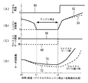
- FIG. 2 is a diagram for explaining characteristic control in the system according to the first embodiment of the present invention.
- the engine 10 is automatically stopped when a predetermined idle stop condition (for example, the accelerator opening is 0 and the engine speed is a specified idle speed) is established.
- a predetermined idle stop condition for example, the accelerator opening is 0 and the engine speed is a specified idle speed
- the accelerator opening (60) becomes 0 at time t0, and then the engine speed (62, 64) decreases to the idle speed, and the engine is automatically stopped at time t1.
- the WGV 38 is in the open state (68)
- the turbo speed (72) is greatly reduced.
- the acceleration performance is deteriorated when accelerating immediately after the engine restart at time t2 (for example, when the engine is restarted and accelerated after an idle stop during a temporary stop due to a signal or the like) (64).
- the WGV 38 when the engine is automatically stopped by the idle stop control, the WGV 38 is controlled to be in the closed state (66). As described above, the WGV 38 can be forcibly controlled by electronic control. By setting the WGV 38 in the closed state at the time of idling stop, the decrease in the turbo rotational speed (70) becomes gentler than in the case where the WGV 38 is in the open state (68) (72). Therefore, high acceleration is ensured when accelerating after engine restart at time t2 (62).
- the WGV 38 may stick or move depending on the oil condition, temperature, and time in that state. In such a case, there is a concern that the catalyst warm-up property may deteriorate due to a delay in opening the WGV 38 at the next engine start.
- the WGV 38 is controlled to be closed. Further, after the engine 10 is automatically stopped, the WGV 38 is controlled to be opened when the ignition switch 56 shifts from the ON state (IG-ON) to the OFF state (IG-OFF) by the operation of the driver. Thereby, it is possible to prevent the WGV 38 from sticking, which is a concern when the engine is stopped for a long time. In addition, the catalyst warm-up delay due to the delay in opening the WGV 38 after the next start can be prevented.
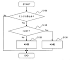
- FIG. 3 is a flowchart of a control routine executed by the ECU 50 in order to realize the above-described operation.
- the idle stop and start function 58 described above is realized in another control routine.
- it is first determined whether or not the engine is stopped (step S100). If the engine is stopped, it is further determined whether the engine is in an “idle stop state” in which the engine 10 is automatically stopped by the idle stop control or an “engine stop state by a driver operation” (step S110). ). Specifically, it is determined whether the ignition switch 56 is in an ON state (IG-ON) or an OFF state (IG-OFF).
- IG-ON ON state
- IG-OFF OFF state
- the ECU 50 controls the WGV 38 to be closed (step S120).
- the ECU 50 controls the WGV 38 to be opened (step S130). Thereafter, the processing of this routine is terminated.
- the WGV 38 can be controlled to be closed in the idle stop state. Therefore, high acceleration can be ensured when the engine 10 is restarted from the idle stop state.
- the WGV 38 can be controlled to be in the open state when the engine is stopped by the operation of the driver. Therefore, the WGV 38 can be prevented from sticking. In addition, the catalyst warm-up delay due to the delay in opening the WGV 38 after the next start can be prevented.
- the engine to which the present invention is applied is not limited to the in-cylinder direct injection engine as in the above-described embodiment.
- the present invention can also be applied to a port injection type engine. Further, the present invention can be applied not only to a spark ignition type engine but also to a compression self-ignition type engine.
- the turbocharger 20 is the “supercharger” in the first invention
- the turbine 20b is the “turbine” in the first invention
- the bypass passage 36 is the first turbocharger.
- the WGV 38 corresponds to the “waste gate valve” in the first invention
- the idle stop and start function 58 corresponds to the “idle stop control means” in the first invention.
- the ECU 50 executes the process of step S120, so that the “waste gate valve closing control means” in the first aspect of the invention executes the process of step S130. “Waste gate valve opening control means” in FIG.
- the “closed state” means “a fully closed state in which the opening degree of the WGV 38 is 0”, but the present invention is not limited to this.
- the WGV 38 may be controlled so that the opening degree of the WGV 38 is smaller than the opening degree at that time.
- the WGV 38 may be controlled so that the opening degree of the WGV 38 is reduced to an opening degree at which sufficient acceleration can be achieved upon subsequent restart.
- “open state” means “a fully open state in which the opening degree of the WGV 38 is maximum”, but the present invention is not limited to this.
- the WGV 38 may be controlled so that the opening degree of the WGV 38 is larger than the opening degree at that time. Preferably, even when the WGV 38 is controlled so that the opening of the WGV 38 can be prevented from sticking while the engine 10 is stopped and the opening of the WGV 38 is sufficient to achieve sufficient catalyst warm-up at the next start. Good.
- the WGV 38 is controlled to be opened when the ignition switch 56 shifts from the ON state to the OFF state by the operation of the driver.
- the WGV 38 may be controlled to be opened when the engine start switch (that is, the switch for starting the internal combustion engine) shifts from the ON state to the OFF state by the operation of the driver.
Landscapes
- Engineering & Computer Science (AREA)
- Chemical & Material Sciences (AREA)
- Combustion & Propulsion (AREA)
- Mechanical Engineering (AREA)
- General Engineering & Computer Science (AREA)
- Supercharger (AREA)
- Output Control And Ontrol Of Special Type Engine (AREA)
Abstract
L'objet de la présente invention est de proposer un dispositif de commande qui doit être utilisé avec un moteur à combustion interne équipé d'un compresseur volumétrique, et qui est capable d'assurer des propriétés d'accélération élevées au redémarrage après un arrêt au ralenti dans un moteur à combustion interne équipé d'un compresseur volumétrique. Le dispositif de commande est pourvu d'une turbine à compresseur volumétrique positionnée dans le tuyau d'échappement du moteur à combustion interne, d'un canal de dérivation permettant de contourner la turbine et de raccorder des sections du tuyau d'échappement qui sont en amont et en aval de la turbine, et d'une soupape de décharge pouvant s'ouvrir/se fermer de manière arbitraire et positionnée dans le clapet de dérivation. De plus, le dispositif de commande arrête automatiquement le moteur à combustion interne lorsqu'une condition prédéterminée d'arrêt au ralenti est satisfaite. La soupape de décharge se ferme lorsque le moteur à combustion interne est arrêté automatiquement.
Priority Applications (1)
| Application Number | Priority Date | Filing Date | Title |
|---|---|---|---|
| PCT/JP2012/061901 WO2013168247A1 (fr) | 2012-05-09 | 2012-05-09 | Dispositif de commande pour moteur à combustion interne équipé d'un compresseur volumétrique |
Applications Claiming Priority (1)
| Application Number | Priority Date | Filing Date | Title |
|---|---|---|---|
| PCT/JP2012/061901 WO2013168247A1 (fr) | 2012-05-09 | 2012-05-09 | Dispositif de commande pour moteur à combustion interne équipé d'un compresseur volumétrique |
Publications (1)
| Publication Number | Publication Date |
|---|---|
| WO2013168247A1 true WO2013168247A1 (fr) | 2013-11-14 |
Family
ID=49550332
Family Applications (1)
| Application Number | Title | Priority Date | Filing Date |
|---|---|---|---|
| PCT/JP2012/061901 Ceased WO2013168247A1 (fr) | 2012-05-09 | 2012-05-09 | Dispositif de commande pour moteur à combustion interne équipé d'un compresseur volumétrique |
Country Status (1)
| Country | Link |
|---|---|
| WO (1) | WO2013168247A1 (fr) |
Cited By (2)
| Publication number | Priority date | Publication date | Assignee | Title |
|---|---|---|---|---|
| JP2016011632A (ja) * | 2014-06-30 | 2016-01-21 | 日産自動車株式会社 | 内燃機関の制御装置 |
| JP2022107376A (ja) * | 2021-01-08 | 2022-07-21 | トヨタ自動車株式会社 | エンジン装置 |
Citations (5)
| Publication number | Priority date | Publication date | Assignee | Title |
|---|---|---|---|---|
| JPH03100325A (ja) * | 1989-09-13 | 1991-04-25 | Mazda Motor Corp | 過給機付エンジンの制御装置 |
| JP2008180176A (ja) * | 2007-01-25 | 2008-08-07 | Toyota Motor Corp | 多気筒内燃機関の排気システム |
| JP2009197738A (ja) * | 2008-02-22 | 2009-09-03 | Mazda Motor Corp | エンジンの自動停止装置 |
| JP2011179336A (ja) * | 2010-02-26 | 2011-09-15 | Daihatsu Motor Co Ltd | 内燃機関の過給システム |
| JP2011214413A (ja) * | 2010-03-31 | 2011-10-27 | Mazda Motor Corp | ディーゼルエンジンの自動停止装置 |
-
2012
- 2012-05-09 WO PCT/JP2012/061901 patent/WO2013168247A1/fr not_active Ceased
Patent Citations (5)
| Publication number | Priority date | Publication date | Assignee | Title |
|---|---|---|---|---|
| JPH03100325A (ja) * | 1989-09-13 | 1991-04-25 | Mazda Motor Corp | 過給機付エンジンの制御装置 |
| JP2008180176A (ja) * | 2007-01-25 | 2008-08-07 | Toyota Motor Corp | 多気筒内燃機関の排気システム |
| JP2009197738A (ja) * | 2008-02-22 | 2009-09-03 | Mazda Motor Corp | エンジンの自動停止装置 |
| JP2011179336A (ja) * | 2010-02-26 | 2011-09-15 | Daihatsu Motor Co Ltd | 内燃機関の過給システム |
| JP2011214413A (ja) * | 2010-03-31 | 2011-10-27 | Mazda Motor Corp | ディーゼルエンジンの自動停止装置 |
Cited By (3)
| Publication number | Priority date | Publication date | Assignee | Title |
|---|---|---|---|---|
| JP2016011632A (ja) * | 2014-06-30 | 2016-01-21 | 日産自動車株式会社 | 内燃機関の制御装置 |
| JP2022107376A (ja) * | 2021-01-08 | 2022-07-21 | トヨタ自動車株式会社 | エンジン装置 |
| JP7512905B2 (ja) | 2021-01-08 | 2024-07-09 | トヨタ自動車株式会社 | エンジン装置 |
Similar Documents
| Publication | Publication Date | Title |
|---|---|---|
| JP5293897B2 (ja) | 内燃機関の制御装置 | |
| US8978378B2 (en) | Method and system for reducing turbocharger noise during cold start | |
| JP6275181B2 (ja) | 電動ウェイストゲートバルブ制御装置 | |
| EP2963263B1 (fr) | Dispositif de commande pour moteur à combustion interne | |
| JP5672417B2 (ja) | 内燃機関の制御装置及び制御方法 | |
| CN104053888A (zh) | 内燃机的控制装置 | |
| WO2012137345A1 (fr) | Appareil de commande de moteur à combustion interne équipé d'un compresseur volumétrique | |
| CN108463620A (zh) | 废气旁通阀的控制方法及控制装置 | |
| WO2011033686A1 (fr) | Dispositif de détermination d'anomalie de soupape de commande pour moteur à combustion interne | |
| CN103237968A (zh) | 带增压器的内燃机的控制装置 | |
| JP4941534B2 (ja) | 内燃機関のウエストゲートバルブ制御装置 | |
| WO2013118263A1 (fr) | Dispositif de commande pour moteur à combustion interne | |
| JP2015132204A (ja) | 内燃機関のバルブの基準位置学習装置 | |
| CN103547781B (zh) | 内燃机的控制装置 | |
| JP6132092B2 (ja) | エンジンの制御装置 | |
| JP5649343B2 (ja) | 内燃機関の吸気絞り弁制御方法 | |
| JP2008075589A (ja) | 内燃機関のegrガス掃気装置 | |
| JP2011190771A (ja) | 内燃機関の制御装置 | |
| WO2013168247A1 (fr) | Dispositif de commande pour moteur à combustion interne équipé d'un compresseur volumétrique | |
| JP5930288B2 (ja) | 内燃機関 | |
| JP6201439B2 (ja) | 内燃機関の制御装置および制御方法 | |
| JP2007303294A (ja) | 過給機付き内燃機関の制御装置 | |
| JP2012188994A (ja) | 過給機付き内燃機関の制御装置 | |
| JP2006017053A (ja) | 過給機付き内燃機関の燃料噴射時期制御装置 | |
| JP2014231821A (ja) | 過給機付き内燃機関の制御装置 |
Legal Events
| Date | Code | Title | Description |
|---|---|---|---|
| 121 | Ep: the epo has been informed by wipo that ep was designated in this application |
Ref document number: 12876237 Country of ref document: EP Kind code of ref document: A1 |
|
| NENP | Non-entry into the national phase |
Ref country code: DE |
|
| 122 | Ep: pct application non-entry in european phase |
Ref document number: 12876237 Country of ref document: EP Kind code of ref document: A1 |
|
| NENP | Non-entry into the national phase |
Ref country code: JP |