WO2013168620A1 - 温度ヒューズ可動電極用の電極材料 - Google Patents
温度ヒューズ可動電極用の電極材料 Download PDFInfo
- Publication number
- WO2013168620A1 WO2013168620A1 PCT/JP2013/062483 JP2013062483W WO2013168620A1 WO 2013168620 A1 WO2013168620 A1 WO 2013168620A1 JP 2013062483 W JP2013062483 W JP 2013062483W WO 2013168620 A1 WO2013168620 A1 WO 2013168620A1
- Authority
- WO
- WIPO (PCT)
- Prior art keywords
- alloy
- layer
- cuo
- electrode material
- electrode
- Prior art date
- Legal status (The legal status is an assumption and is not a legal conclusion. Google has not performed a legal analysis and makes no representation as to the accuracy of the status listed.)
- Ceased
Links
Images

Classifications
-
- H—ELECTRICITY
- H01—ELECTRIC ELEMENTS
- H01H—ELECTRIC SWITCHES; RELAYS; SELECTORS; EMERGENCY PROTECTIVE DEVICES
- H01H85/00—Protective devices in which the current flows through a part of fusible material and this current is interrupted by displacement of the fusible material when this current becomes excessive
- H01H85/02—Details
- H01H85/04—Fuses, i.e. expendable parts of the protective device, e.g. cartridges
- H01H85/05—Component parts thereof
- H01H85/143—Electrical contacts; Fastening fusible members to such contacts
-
- C—CHEMISTRY; METALLURGY
- C22—METALLURGY; FERROUS OR NON-FERROUS ALLOYS; TREATMENT OF ALLOYS OR NON-FERROUS METALS
- C22C—ALLOYS
- C22C5/00—Alloys based on noble metals
- C22C5/06—Alloys based on silver
-
- B—PERFORMING OPERATIONS; TRANSPORTING
- B32—LAYERED PRODUCTS
- B32B—LAYERED PRODUCTS, i.e. PRODUCTS BUILT-UP OF STRATA OF FLAT OR NON-FLAT, e.g. CELLULAR OR HONEYCOMB, FORM
- B32B15/00—Layered products comprising a layer of metal
- B32B15/01—Layered products comprising a layer of metal all layers being exclusively metallic
-
- B—PERFORMING OPERATIONS; TRANSPORTING
- B32—LAYERED PRODUCTS
- B32B—LAYERED PRODUCTS, i.e. PRODUCTS BUILT-UP OF STRATA OF FLAT OR NON-FLAT, e.g. CELLULAR OR HONEYCOMB, FORM
- B32B15/00—Layered products comprising a layer of metal
- B32B15/01—Layered products comprising a layer of metal all layers being exclusively metallic
- B32B15/018—Layered products comprising a layer of metal all layers being exclusively metallic one layer being formed of a noble metal or a noble metal alloy
-
- C—CHEMISTRY; METALLURGY
- C22—METALLURGY; FERROUS OR NON-FERROUS ALLOYS; TREATMENT OF ALLOYS OR NON-FERROUS METALS
- C22C—ALLOYS
- C22C1/00—Making non-ferrous alloys
- C22C1/02—Making non-ferrous alloys by melting
-
- C—CHEMISTRY; METALLURGY
- C22—METALLURGY; FERROUS OR NON-FERROUS ALLOYS; TREATMENT OF ALLOYS OR NON-FERROUS METALS
- C22C—ALLOYS
- C22C5/00—Alloys based on noble metals
- C22C5/06—Alloys based on silver
- C22C5/08—Alloys based on silver with copper as the next major constituent
-
- C—CHEMISTRY; METALLURGY
- C22—METALLURGY; FERROUS OR NON-FERROUS ALLOYS; TREATMENT OF ALLOYS OR NON-FERROUS METALS
- C22C—ALLOYS
- C22C9/00—Alloys based on copper
-
- C—CHEMISTRY; METALLURGY
- C22—METALLURGY; FERROUS OR NON-FERROUS ALLOYS; TREATMENT OF ALLOYS OR NON-FERROUS METALS
- C22F—CHANGING THE PHYSICAL STRUCTURE OF NON-FERROUS METALS AND NON-FERROUS ALLOYS
- C22F1/00—Changing the physical structure of non-ferrous metals or alloys by heat treatment or by hot or cold working
- C22F1/14—Changing the physical structure of non-ferrous metals or alloys by heat treatment or by hot or cold working of noble metals or alloys based thereon
-
- H—ELECTRICITY
- H01—ELECTRIC ELEMENTS
- H01H—ELECTRIC SWITCHES; RELAYS; SELECTORS; EMERGENCY PROTECTIVE DEVICES
- H01H1/00—Contacts
- H01H1/02—Contacts characterised by the material thereof
- H01H1/021—Composite material
- H01H1/023—Composite material having a noble metal as the basic material
- H01H1/0237—Composite material having a noble metal as the basic material and containing oxides
-
- H—ELECTRICITY
- H01—ELECTRIC ELEMENTS
- H01H—ELECTRIC SWITCHES; RELAYS; SELECTORS; EMERGENCY PROTECTIVE DEVICES
- H01H11/00—Apparatus or processes specially adapted for the manufacture of electric switches
- H01H11/04—Apparatus or processes specially adapted for the manufacture of electric switches of switch contacts
- H01H11/041—Apparatus or processes specially adapted for the manufacture of electric switches of switch contacts by bonding of a contact marking face to a contact body portion
- H01H11/042—Apparatus or processes specially adapted for the manufacture of electric switches of switch contacts by bonding of a contact marking face to a contact body portion by mechanical deformation
-
- H—ELECTRICITY
- H01—ELECTRIC ELEMENTS
- H01H—ELECTRIC SWITCHES; RELAYS; SELECTORS; EMERGENCY PROTECTIVE DEVICES
- H01H11/00—Apparatus or processes specially adapted for the manufacture of electric switches
- H01H11/04—Apparatus or processes specially adapted for the manufacture of electric switches of switch contacts
- H01H11/041—Apparatus or processes specially adapted for the manufacture of electric switches of switch contacts by bonding of a contact marking face to a contact body portion
- H01H2011/047—Apparatus or processes specially adapted for the manufacture of electric switches of switch contacts by bonding of a contact marking face to a contact body portion on both sides of the contact body portion
-
- H—ELECTRICITY
- H01—ELECTRIC ELEMENTS
- H01H—ELECTRIC SWITCHES; RELAYS; SELECTORS; EMERGENCY PROTECTIVE DEVICES
- H01H37/00—Thermally-actuated switches
- H01H37/74—Switches in which only the opening movement or only the closing movement of a contact is effected by heating or cooling
- H01H37/76—Contact member actuated by melting of fusible material, actuated due to burning of combustible material or due to explosion of explosive material
- H01H37/764—Contact member actuated by melting of fusible material, actuated due to burning of combustible material or due to explosion of explosive material in which contacts are held closed by a thermal pellet
- H01H37/765—Contact member actuated by melting of fusible material, actuated due to burning of combustible material or due to explosion of explosive material in which contacts are held closed by a thermal pellet using a sliding contact between a metallic cylindrical housing and a central electrode
Definitions
- the present invention relates to an electrode material, and more particularly to a material suitable for a movable electrode of a thermal fuse.
- FIG. 1 shows the structure of a general thermal fuse.
- the thermal fuse 1 lead wires 21 and 22 are connected to a case 10 made of a conductive metal, and an insulating material 30, springs 41 and 42, a movable electrode 50, and a fusible body 60 are housed inside the case 10. Yes.
- the spring 41 is installed between the movable electrode 50 and the insulating material 30, and the spring 42 is installed between the movable electrode 50 and the fusible body 60.
- the movable electrode 50 is in a movable state while being in contact with the inner surface of the case 10.
- the thermal fuse is adapted to energize the lead wire 21 from the lead wire 21 to the movable electrode 50 and the case 10 and further to the lead wire 22 in a normal state (state of FIG. 1).
- the fusible body 60 is deformed and melted at a predetermined operating temperature (generally around 240 ° C.), so that the spring 42 is extended by unloading, and at the same time, the spring 41 is extended, so that the movable electrode 50 moves away from the lead wire 21.
- a predetermined operating temperature generally around 240 ° C.
- the constituent material of the movable electrode of the thermal fuse having the above operating mechanism is required to have resistance to welding to the lead wire and the inner surface of the case in addition to the conductivity as the electrode material. This is because the movable electrode is always energized under the contact state with the lead wire, but if welding occurs, it causes a malfunction of the thermal fuse.
- an Ag—CuO-based oxide dispersion alloy is known as a constituent material of a conventional movable electrode (Patent Document 1: Hereinafter, this Ag—CuO-based oxide dispersion alloy is referred to as an Ag—CuO-based alloy).
- An Ag-CuO alloy is an alloy in which Ag is used as a matrix and CuO is dispersed. It has excellent welding resistance, high conductivity and stable low contact resistance characteristics, and has the characteristics most required for a movable electrode. .
- the Ag—CuO-based alloy is increasingly used in combination with the fact that it does not use Cd, which is a harmful substance, unlike the Ag—CdO-based alloy used before.
- the Ag—CuO alloy is an alloy whose main component is Ag (silver), it can be said to be a relatively expensive material.
- the thickness of the movable electrode is reduced.
- the excessive reduction in thickness causes a malfunction due to insufficient strength of the movable electrode or a decrease in springiness.
- Ag—CuO-based alloys tend to soften the Ag matrix when heated for a long time at the temperature of use of the thermal fuse (100 ° C. or higher), so that it can be said that it is difficult to easily reduce the cost by making it thinner.
- the welding resistance of the Ag—CuO-based alloy is useful as a movable electrode of a thermal fuse, and it is not easy to change the material from the viewpoint of ensuring the reliability of electrical equipment.
- the present invention provides a material suitable as a constituent material of a movable electrode of a thermal fuse, which can be reduced in cost while being based on an Ag—CuO alloy, and a method for manufacturing the same. With the goal.
- the present inventors have intensively studied and decided to apply an electrode material having a clad structure in which a core material layer made of another conductive metal is inserted into an Ag—CuO-based alloy. This is because by setting the core material layer, the amount of Ag used can be reduced correspondingly, leading to cost reduction. Moreover, it is because welding resistance can be ensured by making the surface of the electrode material an Ag—CuO-based alloy as a clad structure.
- the present inventors adopted Cu as a conductive metal applicable as a core material layer. This is because Cu is a metal having better conductivity than the Ag—CuO-based alloy and is suitable as a constituent metal of the electrode material. However, Cu does not have a strong effect of reinforcing the electrode material in terms of strength, and the strength is greatly deteriorated compared to an Ag—CuO-based alloy particularly in a high temperature range. Further, since Cu in the Ag—CuO-based alloy is an oxide, the Ag—CuO-based alloy and Cu are basically different materials, and it is necessary to ensure the bonding strength between the two layers. Accordingly, the present inventors have conceived the present invention by adding an intermediate layer made of an Ag—Cu alloy between the Ag—CuO alloy layer on the surface and the Cu layer as the core material.
- the present invention that solves the above-described problems is an electrode material that constitutes the movable electrode of the thermal fuse, and is formed on a core material layer, an intermediate layer formed on both surfaces of the core material layer, and the intermediate layer.
- the core layer is made of Cu or a Cu alloy
- the intermediate layer is made of an Ag—Cu alloy
- the surface layer is made of an Ag—CuO oxide.
- the electrode material is made of a dispersion strengthened alloy and has a ratio (intermediate layer / surface layer) between the thickness of the intermediate layer and the surface layer (intermediate layer / surface layer) of 0.2 to 1.0.
- the electrode material according to the present invention has a clad structure in which a plurality of metal layers are laminated as described above.
- each metal layer constituting the present invention will be described in detail.
- the surface-layer Ag—CuO-based alloy is preferably one in which 3 to 12% by mass of Cu is contained and the remaining Ag—Cu alloy is internally oxidized.
- the surface layer of the movable electrode of the thermal fuse is required to have welding resistance, but the welding resistance of the Ag—CuO alloy changes depending on the amount of oxide (CuO) dispersed, and this is an Ag—Cu alloy that internally oxidizes. Depends on the Cu content. Considering this, in order to ensure suitable welding resistance, the Cu content of the internally oxidized Ag—Cu alloy is set to 3 to 12 mass%. Further, as the Ag—CuO-based alloy, 3 to 12% by mass of Cu, 0.03 to 0.7% by mass of Ni, and the remaining Ag—Cu—Ni alloy which is internally oxidized is used. Also good. The significance of the addition of Ni is to refine the CuO particles and improve the strength and welding resistance of the Ag—CuO-based alloy.
- the core material layer is made of Cu, and Cu is preferably a conductive material such as so-called oxygen-free copper (OFC) or tough pitch copper (TPC). This is to ensure the electrical conductivity required for the electrode material.
- OFC oxygen-free copper
- TPC tough pitch copper
- the intermediate layer is set between the surface layer made of the Ag—CuO alloy and the core material layer made of Cu, as described above, to improve the strength of the electrode material and to secure the bonding strength between the surface layer and the core material layer.
- This intermediate layer is made of an Ag—Cu alloy.
- a preferred Ag—Cu alloy is an Ag—Cu alloy containing 3 to 12% by mass of Cu, or Ag—Cu—Ni containing 3 to 12% by mass of Cu and 0.03 to 0.7% by mass of Ni.
- middle layer is a metal layer for ensuring the intensity
- the intermediate layer Ag-Cu alloy (Ag-Cu alloy or Ag-Cu-Ni alloy) is an alloy in which Cu (Ni) is dissolved in Ag, and is more than Ag, which is a matrix of Ag-CuO alloy. Excellent strength and little decrease in strength at high temperatures. Therefore, it can function as a reinforcing layer of the electrode material.
- the Ag—Cu alloy and the Ag—Cu—Ni alloy have a composition similar to that of the Ag—CuO alloy as the surface layer, and also have no dispersion layer, so that the Cu as the core material layer is also present. Familiarity is good. Therefore, it also has the effect
- middle layer and the surface layer shall be 0.2 or more and 1.0 or less.
- the reason why the thickness ratio is 0.2 or more is to secure a strength equal to or higher than that of a conventional Ag—CuO-based alloy single-layer electrode material by ensuring strength reduction due to insertion of a copper layer.
- a thickness ratio of 1.0 or less contributes to an increase in strength as the thickness of the surface layer decreases, but the surface layer is consumed due to arc discharge generated when the temperature fuse operates. This is to prevent deterioration of the welding resistance due to exposure of the underlying intermediate layer.
- the surface layer preferably has a thickness of 15 ⁇ m or more.
- the Ag—CuO-based alloy layer as the surface layer and the Ag—Cu-based alloy layer as the intermediate layer are integrated while having the above thickness ratio.
- the Ag—CuO-based alloy is manufactured by the internal oxidation treatment of the Ag—Cu-based alloy, the surface layer and the intermediate layer are partially made of a single-layer plate material made of an Ag—Cu-based alloy. Those formed by internal oxidation treatment are preferred.
- an Ag—Cu alloy that is partially (surface-only) internally oxidized in this way the surface layer and the intermediate layer are continuous.
- the electrode material according to the present invention is a clad material, it can be made a clad material by rolling and joining plate materials, foil materials, or tape materials constituting each metal layer. That is, it can be produced by rolling and rolling an Ag—CuO alloy, an Ag—Cu alloy (Ag—Cu—Ni alloy), a plate material made of Cu or Cu alloy, and the like.
- An Ag—CuO-based alloy can be manufactured by internal oxidation treatment of an Ag—Cu alloy or an Ag—Cu—Ni alloy.
- a preferable manufacturing method includes a step of joining a plate material made of an Ag—Cu based alloy on both sides of a plate material made of Cu to make a clad material, and a method of heat treating the clad material to make a plate material made of an Ag—Cu based alloy.
- This is a method for producing an electrode material including a step of internally oxidizing a part to form a surface layer made of an Ag—CuO-based oxide dispersion strengthened alloy.
- a clad material of three layers (Ag—Cu alloy / Cu / Ag—Cu alloy) is manufactured first, and the Ag—Cu alloy layer is partially internally oxidized, so that Simplification can be achieved, and the surface layer and the intermediate layer can be integrated.
- the thickness of the Ag—CuO-based alloy layer as the surface layer can be adjusted within the conditions of the internal oxidation treatment described later, and an electrode material having a target structure without allowing oxygen to reach the core material layer (Cu) during the treatment. Can be manufactured.
- a clad material is manufactured in which a plate material made of an Ag—Cu alloy (Ag—Cu—Ni alloy) is rolled and bonded on both surfaces of a core material made of Cu.
- the thickness of the clad bonded plate material may be adjusted by rolling or the like before the internal oxidation treatment.
- the clad material produced above is internally oxidized to form an Ag—CuO-based alloy layer.
- the heat treatment temperature is preferably 500 to 700 ° C.
- the heat treatment temperature is less than 500 ° C., oxygen atoms are not sufficiently diffused in the Ag—Cu alloy, and it takes a considerable time to oxidize a certain depth range from the alloy surface, which is not practical. .
- the heat treatment temperature exceeds 700 ° C., the rate of progress of internal oxidation is too fast, making it difficult to control the thickness of the surface layer.
- the oxygen partial pressure is preferably 0.01 MPa or more and less than 0.3 MPa.
- the oxygen partial pressure is less than 0.01 MPa, it is difficult to supply an oxygen amount necessary for sufficient internal oxidation into the Ag—Cu alloy.
- the oxygen partial pressure is 0.3 MPa or more, the rate of progress of internal oxidation is too high as in the case where the heat treatment temperature is raised, and it becomes difficult to control the thickness of the surface layer.
- the heat treatment time is preferably 3 to 15 hours.
- the thickness of the surface layer is controlled by the heat treatment temperature, oxygen partial pressure, and heat treatment time. If the heat treatment time is short, the predetermined surface layer thickness cannot be obtained, and if it is too long, the intermediate layer becomes thin and the strength deteriorates. In addition, when the oxidation reaches the interface between the intermediate layer and the core material layer, the core material layer is oxidized, thereby remarkably deteriorating the bonding strength between the intermediate layer and the core material layer.
- an Ag—CuO-based alloy layer can be formed and an electrode material having a five-layer structure can be manufactured.
- the clad material manufactured in this way may then be rolled as necessary to adjust the overall thickness. Then, cutting, slitting, and bending can be performed into shapes and dimensions necessary for the movable electrode of the thermal fuse.
- the electrode material according to the present invention is suitable for a movable electrode of a thermal fuse, and the material cost can be reduced by combining Cu with an Ag—CuO alloy to form a clad material.
- the intermediate layer by setting the intermediate layer, contact with the case of the thermal fuse can be stably maintained without lowering the strength and springiness even under heating.
- the surface layer is an Ag—CuO-based alloy, and the welding resistance originally required for the movable electrode is also good.
- Cu is applied as a core material layer, and an Ag—Cu alloy (Cu content: 10 mass%) as an intermediate layer on both sides of the core material layer and an Ag—CuO alloy (Cu
- An electrode material having a five-layer clad structure with a content of 10% by mass (12% by mass in terms of CuO) was produced, and its characteristics were evaluated.
- Example 1 First, each metal was weighed so that the alloy composition was Ag: 90.0 mass% and Cu: 10.0 mass%, and the Ag—Cu alloy was melted and cast. Thereafter, an Ag—Cu alloy ingot was rolled to a thickness of 4.15 mm and cut to produce an Ag—Cu alloy plate having a width of 115 mm and a length of 195 mm. Then, the oxygen-free copper ingot is rolled to produce a Cu plate having a width of 120 mm, a length of 200 mm, and a thickness of 9 mm. After being held at 800 ° C. for 60 minutes in a mixed gas of nitrogen and hydrogen, hot pressing was performed at a pressure of 100 ton. The clad material of the three layers (Ag—Cu alloy / Cu / Ag—Cu alloy) thus press-bonded was rolled to produce a clad material tape.
- the above clad tape is rolled to 450 ⁇ m to form a three-layer clad tape comprising a 110 ⁇ m thick Ag—Cu alloy layer and a 230 ⁇ m thick core material layer.
- the thickness ratio between the Ag—Cu alloy layer and the core material layer was almost the same as the thickness ratio between the Ag—Cu alloy plate and the Cu plate before being pressed.
- This three-layer clad material tape was internally oxidized to form an Ag—CuO alloy layer as a surface layer.
- the internal oxidation treatment was carried out in an internal oxidation furnace under the conditions of heat treatment temperature: 600 ° C., oxygen partial pressure: 0.02 MPa, and heat treatment time: 8 hours.
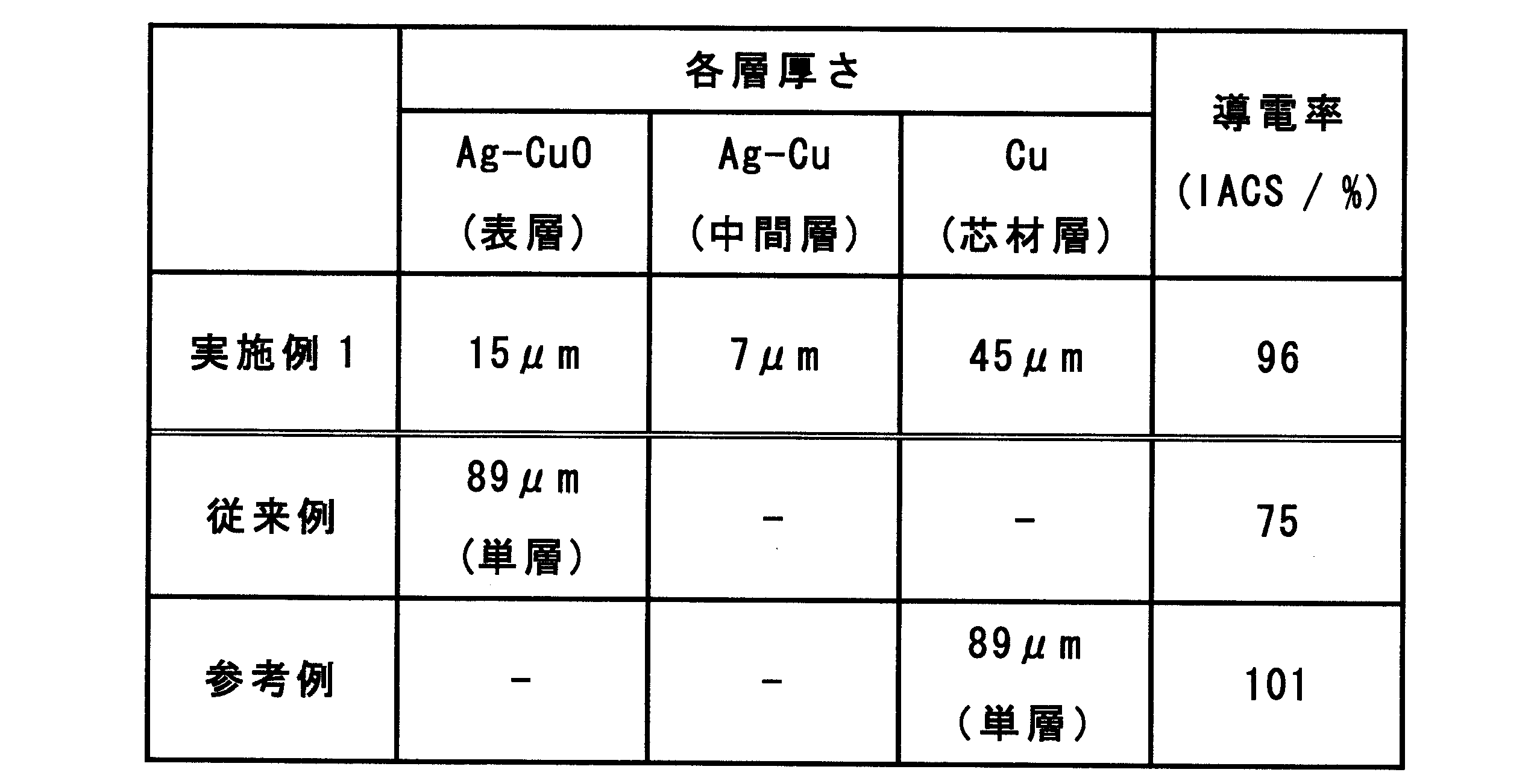
- the manufactured clad tape has a total thickness of 89 ⁇ m of Ag—CuO (15 ⁇ m) / Ag—Cu (7 ⁇ m) / Cu (45 ⁇ m) / Ag—Cu (7 ⁇ m) / Ag—CuO (15 ⁇ m).
- the obtained clad tape was cut and used as an electrode material for evaluation having dimensions of 7 mm in width and 50 mm in length. In addition, the thickness of each layer was measured from cross-sectional observation with a metal microscope.
- Example 2 In Example 1, the heat treatment time was set to 10 hours during internal oxidation of the three-layer clad material (Ag—Cu alloy / Cu / Ag—Cu alloy). As a result, the thickness of the Ag—CuO alloy layer was 91 ⁇ m, and the thickness of the Ag—Cu alloy layer was 19 ⁇ m. Thereafter, rolling was performed in the same manner as in Example 1 to produce a clad tape having a five-layer structure. The manufactured clad tape has a total thickness of Ag—CuO (18.3 ⁇ m) / Ag—Cu (3.7 ⁇ m) / Cu (45 ⁇ m) / Ag—Cu (3.7 ⁇ m) / Ag—CuO (18.3 ⁇ m). 89 ⁇ m. The obtained clad tape was cut and used as an electrode material for evaluation.
- Example 3 In Example 1, the heat treatment time was set to 3 hours during the internal oxidation of the three-layer clad material (Ag—Cu alloy / Cu / Ag—Cu alloy). As a result, the thickness of the Ag—CuO alloy layer was 55 ⁇ m, and the thickness of the Ag—Cu alloy layer was 55 ⁇ m. Thereafter, rolling was performed in the same manner as in Example 1 to produce a clad tape having a five-layer structure.
- the manufactured clad tape has a total thickness of 89 ⁇ m of Ag—CuO (11 ⁇ m) / Ag—Cu (11 ⁇ m) / Cu (45 ⁇ m) / Ag—Cu (11 ⁇ m) / Ag—CuO (11 ⁇ m).
- the obtained clad tape was cut and used as an electrode material for evaluation.
- Example 1 In Example 1, the heat treatment time was 12 hours during the internal oxidation of the three-layer clad material (Ag—Cu alloy / Cu / Ag—Cu alloy). As a result, the thickness of the Ag—CuO alloy layer was 100 ⁇ m, and the thickness of the Ag—Cu alloy layer was 10 ⁇ m. Thereafter, rolling was performed in the same manner as in Example 1 to produce a clad tape having a five-layer structure.
- the manufactured clad tape has a total thickness of 89 ⁇ m of Ag—CuO (20 ⁇ m) / Ag—Cu (2 ⁇ m) / Cu (45 ⁇ m) / Ag—Cu (2 ⁇ m) / Ag—CuO (20 ⁇ m).
- the obtained clad tape was cut and used as an electrode material for evaluation.
- the spring limit value tends to increase as the thickness of the Ag—Cu alloy layer as the intermediate layer increases (the ratio increases).
- the thickness of the intermediate layer is thin (intermediate layer / surface layer: 0.1), and the strength is equivalent to that of the conventional Ag—CuO alloy powder material.
- the introduction of the copper layer, which is the core material layer aims to reduce the cost by reducing the amount of Ag used.
- the Ag—Cu alloy layer is 0.2 times the surface layer.
- the conductivity (% IACS) was measured for each electrode material of Example 1, the conventional example, and the reference example, and the conductivity was evaluated. Conductivity is measured by cutting each electrode material with a thickness of 89 ⁇ m into a width of 7mm and a length of 150mm, measuring the electrical resistance by clamping a current terminal at both ends and a voltage terminal between the inner 100mm, and calculating IACS. did. The measurement results are shown in Table 2.
- Example 1 From the results shown in Table 2, by using Cu having higher conductivity than the Ag—CuO alloy as the core material layer as in Example 1, the conductivity is higher than that of the conventional Ag—CuO alloy single layer material. I understood it.
- the conductivity of Example 1 was a characteristic approaching that of an electrode material having a single copper layer.
- the present invention employs a clad structure in which an Ag—Cu alloy layer as an intermediate layer is set while using a copper layer as a core material, thereby providing an electrode material that is excellent in conductivity and can achieve both cost and strength. It is suitable for a movable electrode of a thermal fuse.
- the thickness of the intermediate layer within an appropriate range, the surface-layer Ag—CuO alloy has excellent welding resistance. According to the present invention, it is possible to suppress malfunction of the thermal fuse, and to ensure the reliability of various electric devices.
Landscapes
- Chemical & Material Sciences (AREA)
- Engineering & Computer Science (AREA)
- Materials Engineering (AREA)
- Mechanical Engineering (AREA)
- Metallurgy (AREA)
- Organic Chemistry (AREA)
- Composite Materials (AREA)
- Manufacturing & Machinery (AREA)
- Physics & Mathematics (AREA)
- Thermal Sciences (AREA)
- Crystallography & Structural Chemistry (AREA)
- Combustion & Propulsion (AREA)
- Contacts (AREA)
- Fuses (AREA)
Abstract
Description

Claims (7)
- 温度ヒューズの可動電極を構成する電極材料において、
芯材層と、前記芯材層の両面上に形成された中間層と、前記中間層上に形成される表層とからなる5層のクラッド構造を有し、
前記芯材層は、Cuからなり、
前記中間層は、Ag-Cu系合金からなり、
前記表層は、Ag-CuO系酸化物分散強化合金からなり、
前記中間層の厚さと、前記表層の厚さとの比(中間層/表層)が0.2以上1.0以下である電極材料。 - 表層を構成するAg-CuO系酸化物分散強化合金は、Cu:3~12質量%、残部AgのAg-Cu合金、又は、Cu:3~12質量%、Ni:0.03~0.7質量%、残部AgのAg-Cu-Ni合金のいずれかを内部酸化処理したものである請求項1記載の電極材料。
- 中間層を構成するAg-Cu系合金は、Cu:3~12質量%、残部AgのAg-Cu合金又はCu:3~12質量%、Ni:0.03~0.7質量%、残部AgのAg-Cu-Ni合金からなる請求項1又は請求項2記載の電極材料。
- 芯材層を構成するCuは、無酸素銅又はタフピッチ銅のいずれかである請求項1~請求項3のいずれかに記載の電極材料。
- 中間層及び表層は、Ag-Cu系合金からなる単層の板材を、部分的に内部酸化処理して形成されるものである請求項1~請求項4のいずれかに記載の電極材料。
- 請求項1~請求項5のいずれかに記載の電極材料の製造方法であって、
Cuからなる板材の両面にAg-Cu系合金からなる板材を接合してクラッド材とする工程と、
前記クラッド材を熱処理してAg-Cu系合金からなる板材の一部を内部酸化させ、Ag-CuO系酸化物分散強化合金からなる表層を形成する工程と、を含む電極材料の製造方法。 - Ag-Cu系合金を部分的に内部酸化する処理は、熱処理温度:500~700℃、酸素分圧:0.01MPa~0.3MPa、熱処理時間:3~15時間とする請求項6記載の電極材料の製造方法。
Priority Applications (4)
| Application Number | Priority Date | Filing Date | Title |
|---|---|---|---|
| CN201380024158.6A CN104272419B (zh) | 2012-05-07 | 2013-04-26 | 用于温度保险丝可动电极的电极材料 |
| US14/389,911 US10176958B2 (en) | 2012-05-07 | 2013-04-26 | Electrode material for thermal-fuse movable electrode |
| KR1020147034013A KR101649064B1 (ko) | 2012-05-07 | 2013-04-26 | 온도 퓨즈 가동 전극용의 전극 재료 |
| EP13787476.4A EP2849194B1 (en) | 2012-05-07 | 2013-04-26 | Electrode material for thermal-fuse movable electrode |
Applications Claiming Priority (2)
| Application Number | Priority Date | Filing Date | Title |
|---|---|---|---|
| JP2012106037A JP5923378B2 (ja) | 2012-05-07 | 2012-05-07 | 温度ヒューズ可動電極用の電極材料 |
| JP2012-106037 | 2012-05-07 |
Publications (1)
| Publication Number | Publication Date |
|---|---|
| WO2013168620A1 true WO2013168620A1 (ja) | 2013-11-14 |
Family
ID=49550665
Family Applications (1)
| Application Number | Title | Priority Date | Filing Date |
|---|---|---|---|
| PCT/JP2013/062483 Ceased WO2013168620A1 (ja) | 2012-05-07 | 2013-04-26 | 温度ヒューズ可動電極用の電極材料 |
Country Status (6)
| Country | Link |
|---|---|
| US (1) | US10176958B2 (ja) |
| EP (1) | EP2849194B1 (ja) |
| JP (1) | JP5923378B2 (ja) |
| KR (1) | KR101649064B1 (ja) |
| CN (1) | CN104272419B (ja) |
| WO (1) | WO2013168620A1 (ja) |
Families Citing this family (6)
| Publication number | Priority date | Publication date | Assignee | Title |
|---|---|---|---|---|
| WO2017204129A1 (ja) * | 2016-05-23 | 2017-11-30 | 田中貴金属工業株式会社 | 電気接点用のクラッド材及び該クラッド材の製造方法 |
| CN109585235B (zh) * | 2018-12-14 | 2019-11-12 | 郑州机械研究所有限公司 | 一种三明治结构银铜熔体 |
| JP7524156B2 (ja) * | 2021-12-20 | 2024-07-29 | ショット日本株式会社 | 温度ヒューズ用接点材およびこれを用いた感温ペレット型温度ヒューズ |
| CN115527817A (zh) * | 2022-09-01 | 2022-12-27 | 浙江福达合金材料科技有限公司 | 银金属氧化物电接触材料及其制备方法和在有机物型温度保险丝中的应用 |
| CN117766356A (zh) * | 2022-09-16 | 2024-03-26 | 热敏碟公司 | 用于高功率应用的热切断装置 |
| CN119305266A (zh) * | 2024-10-14 | 2025-01-14 | 浙江福达合金材料科技有限公司 | 一种AgMeO复Cu带材及其在有机物型温度保险丝中的应用 |
Citations (8)
| Publication number | Priority date | Publication date | Assignee | Title |
|---|---|---|---|---|
| JPS56169320U (ja) * | 1980-05-17 | 1981-12-15 | ||
| JPS62241211A (ja) * | 1986-04-11 | 1987-10-21 | 中外電気工業株式会社 | 点溶接可能なテ−プ状電気接点材料 |
| JPH025844U (ja) * | 1988-06-24 | 1990-01-16 | ||
| JPH02179369A (ja) * | 1988-12-29 | 1990-07-12 | Tokuriki Honten Co Ltd | Ag―酸化物系複合接点材料およびその製造方法 |
| JPH0547252A (ja) * | 1991-08-15 | 1993-02-26 | Furukawa Electric Co Ltd:The | 電気接点材料とその製造方法 |
| JP2001192863A (ja) * | 2000-01-11 | 2001-07-17 | Furukawa Electric Co Ltd:The | 銅合金材料およびその製造方法 |
| WO2003009323A1 (en) * | 2001-07-18 | 2003-01-30 | Nec Schott Components Corporation | Thermal fuse |
| JP2011137198A (ja) | 2009-12-28 | 2011-07-14 | Tokuriki Honten Co Ltd | 電極材料およびその製造方法 |
Family Cites Families (14)
| Publication number | Priority date | Publication date | Assignee | Title |
|---|---|---|---|---|
| US4523711A (en) * | 1980-09-18 | 1985-06-18 | Fuji Electric Co., Ltd. | Method for bonding silver-based contact |
| JPS56169320A (en) | 1981-04-15 | 1981-12-26 | Shunpei Yamazaki | Silicon carbide semiconductor |
| JPS60248842A (ja) * | 1984-05-24 | 1985-12-09 | Tanaka Kikinzoku Kogyo Kk | 電気接点材料 |
| JPH025844A (ja) | 1988-06-22 | 1990-01-10 | Idemitsu Petrochem Co Ltd | 食品用包装容器 |
| JP2641547B2 (ja) * | 1988-12-29 | 1997-08-13 | 株式会社徳力本店 | インレイクラッド材の製造方法 |
| JP2714555B2 (ja) * | 1992-09-17 | 1998-02-16 | 科学技術庁金属材料技術研究所長 | 高強度・高導電率銅合金板材 |
| JP3856073B2 (ja) * | 1999-07-28 | 2006-12-13 | 住友電気工業株式会社 | Cu−Ag合金の製造方法 |
| JP3539370B2 (ja) | 2000-08-24 | 2004-07-07 | 東陶機器株式会社 | 健康管理ネットワークシステム |
| KR100462685B1 (ko) * | 2002-12-03 | 2004-12-23 | 엔이씨 쇼트 컴포넌츠 가부시키가이샤 | 온도 퓨즈 |
| JP4932465B2 (ja) * | 2006-12-14 | 2012-05-16 | 株式会社徳力本店 | Ag−酸化物系電気接点材料およびその製造方法 |
| EP2200056A1 (en) * | 2007-09-26 | 2010-06-23 | The Furukawa Electric Co., Ltd. | Silver-clad composite material for movable contacts and process for production thereof |
| CN101562081B (zh) * | 2008-04-18 | 2012-03-21 | 佛山通宝精密合金股份有限公司 | 一种节银型层状复合触头片件的制备方法 |
| KR101648645B1 (ko) * | 2011-07-06 | 2016-08-16 | 가부시키가이샤 토쿠리키 혼텐 | 온도 퓨즈용 전극 재료 및 그 제조 방법과 그 전극 재료를 이용한 온도 퓨즈 |
| KR101955747B1 (ko) * | 2011-11-22 | 2019-03-07 | 쇼트 니혼 가부시키가이샤 | 온도 퓨즈 및 당해 온도 퓨즈에 이용되는 활주전극 |
-
2012
- 2012-05-07 JP JP2012106037A patent/JP5923378B2/ja active Active
-
2013
- 2013-04-26 EP EP13787476.4A patent/EP2849194B1/en active Active
- 2013-04-26 WO PCT/JP2013/062483 patent/WO2013168620A1/ja not_active Ceased
- 2013-04-26 CN CN201380024158.6A patent/CN104272419B/zh active Active
- 2013-04-26 US US14/389,911 patent/US10176958B2/en active Active
- 2013-04-26 KR KR1020147034013A patent/KR101649064B1/ko active Active
Patent Citations (8)
| Publication number | Priority date | Publication date | Assignee | Title |
|---|---|---|---|---|
| JPS56169320U (ja) * | 1980-05-17 | 1981-12-15 | ||
| JPS62241211A (ja) * | 1986-04-11 | 1987-10-21 | 中外電気工業株式会社 | 点溶接可能なテ−プ状電気接点材料 |
| JPH025844U (ja) * | 1988-06-24 | 1990-01-16 | ||
| JPH02179369A (ja) * | 1988-12-29 | 1990-07-12 | Tokuriki Honten Co Ltd | Ag―酸化物系複合接点材料およびその製造方法 |
| JPH0547252A (ja) * | 1991-08-15 | 1993-02-26 | Furukawa Electric Co Ltd:The | 電気接点材料とその製造方法 |
| JP2001192863A (ja) * | 2000-01-11 | 2001-07-17 | Furukawa Electric Co Ltd:The | 銅合金材料およびその製造方法 |
| WO2003009323A1 (en) * | 2001-07-18 | 2003-01-30 | Nec Schott Components Corporation | Thermal fuse |
| JP2011137198A (ja) | 2009-12-28 | 2011-07-14 | Tokuriki Honten Co Ltd | 電極材料およびその製造方法 |
Non-Patent Citations (1)
| Title |
|---|
| See also references of EP2849194A1 |
Also Published As
| Publication number | Publication date |
|---|---|
| CN104272419A (zh) | 2015-01-07 |
| JP2013235674A (ja) | 2013-11-21 |
| CN104272419B (zh) | 2017-04-05 |
| EP2849194A1 (en) | 2015-03-18 |
| US10176958B2 (en) | 2019-01-08 |
| EP2849194A4 (en) | 2016-06-01 |
| JP5923378B2 (ja) | 2016-05-24 |
| KR101649064B1 (ko) | 2016-08-30 |
| US20150054613A1 (en) | 2015-02-26 |
| EP2849194B1 (en) | 2018-05-30 |
| KR20150008443A (ko) | 2015-01-22 |
Similar Documents
| Publication | Publication Date | Title |
|---|---|---|
| JP5923378B2 (ja) | 温度ヒューズ可動電極用の電極材料 | |
| KR101648645B1 (ko) | 온도 퓨즈용 전극 재료 및 그 제조 방법과 그 전극 재료를 이용한 온도 퓨즈 | |
| JP5730480B2 (ja) | 電極材料およびその製造方法 | |
| JP7153565B2 (ja) | テープ状接点材及びその製造方法 | |
| WO2013141273A1 (ja) | クラッド構造を有する電極材料 | |
| CN101542663B (zh) | 电接点材料的制造方法、电接点材料以及温度熔断器 | |
| CN109155208B (zh) | 电触点用的覆层材料和该覆层材料的制造方法 | |
| CN101145586A (zh) | 太阳能电池用连接引线和它的制造方法及太阳能电池 | |
| KR101552428B1 (ko) | 차단기용 고산화물 은/은 합금계 전기접점 소재 | |
| JP6530267B2 (ja) | 温度ヒューズ用電極材料 | |
| US20230187866A1 (en) | Silver alloy clad structure for charging terminals and manufacturing method thereof | |
| EP3859033B1 (en) | Foil for negative-electrode current collector of secondary cell | |
| EP2974818B1 (en) | Solder joining method | |
| KR101491932B1 (ko) | 은-산화물계 전기접점재료 및 이의 제조방법 | |
| CN101026025A (zh) | 铜银合金导线及其制备方法 | |
| JP4796522B2 (ja) | 配線用導体およびその製造方法 | |
| JP2007157509A (ja) | 配線用電線導体およびそれを用いた配線用電線 | |
| JP4994143B2 (ja) | 銀−酸化物系電気接点材料 | |
| CN117791202A (zh) | 一种银镍/银基金属氧化物触头材料及其制备方法 | |
| WO2014091634A1 (ja) | 温度ヒューズ用電極材料およびその製造方法 |
Legal Events
| Date | Code | Title | Description |
|---|---|---|---|
| 121 | Ep: the epo has been informed by wipo that ep was designated in this application |
Ref document number: 13787476 Country of ref document: EP Kind code of ref document: A1 |
|
| WWE | Wipo information: entry into national phase |
Ref document number: 14389911 Country of ref document: US |
|
| WWE | Wipo information: entry into national phase |
Ref document number: 2013787476 Country of ref document: EP |
|
| NENP | Non-entry into the national phase |
Ref country code: DE |
|
| ENP | Entry into the national phase |
Ref document number: 20147034013 Country of ref document: KR Kind code of ref document: A |