WO2013168800A1 - 注射器 - Google Patents
注射器 Download PDFInfo
- Publication number
- WO2013168800A1 WO2013168800A1 PCT/JP2013/063171 JP2013063171W WO2013168800A1 WO 2013168800 A1 WO2013168800 A1 WO 2013168800A1 JP 2013063171 W JP2013063171 W JP 2013063171W WO 2013168800 A1 WO2013168800 A1 WO 2013168800A1
- Authority
- WO
- WIPO (PCT)
- Prior art keywords
- unit
- injection
- housing
- holding
- drive
- Prior art date
- Legal status (The legal status is an assumption and is not a legal conclusion. Google has not performed a legal analysis and makes no representation as to the accuracy of the status listed.)
- Ceased
Links
Images




Classifications
-
- A—HUMAN NECESSITIES
- A61—MEDICAL OR VETERINARY SCIENCE; HYGIENE
- A61M—DEVICES FOR INTRODUCING MEDIA INTO, OR ONTO, THE BODY; DEVICES FOR TRANSDUCING BODY MEDIA OR FOR TAKING MEDIA FROM THE BODY; DEVICES FOR PRODUCING OR ENDING SLEEP OR STUPOR
- A61M5/00—Devices for bringing media into the body in a subcutaneous, intra-vascular or intramuscular way; Accessories therefor, e.g. filling or cleaning devices, arm-rests
- A61M5/178—Syringes
- A61M5/24—Ampoule syringes, i.e. syringes with needle for use in combination with replaceable ampoules or carpules, e.g. automatic
-
- A—HUMAN NECESSITIES
- A61—MEDICAL OR VETERINARY SCIENCE; HYGIENE
- A61M—DEVICES FOR INTRODUCING MEDIA INTO, OR ONTO, THE BODY; DEVICES FOR TRANSDUCING BODY MEDIA OR FOR TAKING MEDIA FROM THE BODY; DEVICES FOR PRODUCING OR ENDING SLEEP OR STUPOR
- A61M5/00—Devices for bringing media into the body in a subcutaneous, intra-vascular or intramuscular way; Accessories therefor, e.g. filling or cleaning devices, arm-rests
- A61M5/178—Syringes
- A61M5/30—Syringes for injection by jet action, without needle, e.g. for use with replaceable ampoules or carpules
-
- A—HUMAN NECESSITIES
- A61—MEDICAL OR VETERINARY SCIENCE; HYGIENE
- A61M—DEVICES FOR INTRODUCING MEDIA INTO, OR ONTO, THE BODY; DEVICES FOR TRANSDUCING BODY MEDIA OR FOR TAKING MEDIA FROM THE BODY; DEVICES FOR PRODUCING OR ENDING SLEEP OR STUPOR
- A61M5/00—Devices for bringing media into the body in a subcutaneous, intra-vascular or intramuscular way; Accessories therefor, e.g. filling or cleaning devices, arm-rests
- A61M5/178—Syringes
- A61M5/30—Syringes for injection by jet action, without needle, e.g. for use with replaceable ampoules or carpules
- A61M5/3015—Syringes for injection by jet action, without needle, e.g. for use with replaceable ampoules or carpules for injecting a dose of particles in form of powdered drug, e.g. mounted on a rupturable membrane and accelerated by a gaseous shock wave or supersonic gas flow
-
- A—HUMAN NECESSITIES
- A61—MEDICAL OR VETERINARY SCIENCE; HYGIENE
- A61M—DEVICES FOR INTRODUCING MEDIA INTO, OR ONTO, THE BODY; DEVICES FOR TRANSDUCING BODY MEDIA OR FOR TAKING MEDIA FROM THE BODY; DEVICES FOR PRODUCING OR ENDING SLEEP OR STUPOR
- A61M5/00—Devices for bringing media into the body in a subcutaneous, intra-vascular or intramuscular way; Accessories therefor, e.g. filling or cleaning devices, arm-rests
- A61M5/178—Syringes
- A61M5/31—Details
- A61M5/315—Pistons; Piston-rods; Guiding, blocking or restricting the movement of the rod or piston; Appliances on the rod for facilitating dosing ; Dosing mechanisms
- A61M5/31533—Dosing mechanisms, i.e. setting a dose
- A61M5/31535—Means improving security or handling thereof, e.g. blocking means, means preventing insufficient dosing, means allowing correction of overset dose
-
- A—HUMAN NECESSITIES
- A61—MEDICAL OR VETERINARY SCIENCE; HYGIENE
- A61M—DEVICES FOR INTRODUCING MEDIA INTO, OR ONTO, THE BODY; DEVICES FOR TRANSDUCING BODY MEDIA OR FOR TAKING MEDIA FROM THE BODY; DEVICES FOR PRODUCING OR ENDING SLEEP OR STUPOR
- A61M5/00—Devices for bringing media into the body in a subcutaneous, intra-vascular or intramuscular way; Accessories therefor, e.g. filling or cleaning devices, arm-rests
- A61M5/178—Syringes
- A61M5/31—Details
- A61M5/315—Pistons; Piston-rods; Guiding, blocking or restricting the movement of the rod or piston; Appliances on the rod for facilitating dosing ; Dosing mechanisms
- A61M5/31565—Administration mechanisms, i.e. constructional features, modes of administering a dose
- A61M5/31566—Means improving security or handling thereof
-
- A—HUMAN NECESSITIES
- A61—MEDICAL OR VETERINARY SCIENCE; HYGIENE
- A61M—DEVICES FOR INTRODUCING MEDIA INTO, OR ONTO, THE BODY; DEVICES FOR TRANSDUCING BODY MEDIA OR FOR TAKING MEDIA FROM THE BODY; DEVICES FOR PRODUCING OR ENDING SLEEP OR STUPOR
- A61M5/00—Devices for bringing media into the body in a subcutaneous, intra-vascular or intramuscular way; Accessories therefor, e.g. filling or cleaning devices, arm-rests
- A61M5/178—Syringes
- A61M5/31—Details
- A61M5/315—Pistons; Piston-rods; Guiding, blocking or restricting the movement of the rod or piston; Appliances on the rod for facilitating dosing ; Dosing mechanisms
- A61M5/31565—Administration mechanisms, i.e. constructional features, modes of administering a dose
- A61M5/31576—Constructional features or modes of drive mechanisms for piston rods
-
- A—HUMAN NECESSITIES
- A61—MEDICAL OR VETERINARY SCIENCE; HYGIENE
- A61M—DEVICES FOR INTRODUCING MEDIA INTO, OR ONTO, THE BODY; DEVICES FOR TRANSDUCING BODY MEDIA OR FOR TAKING MEDIA FROM THE BODY; DEVICES FOR PRODUCING OR ENDING SLEEP OR STUPOR
- A61M5/00—Devices for bringing media into the body in a subcutaneous, intra-vascular or intramuscular way; Accessories therefor, e.g. filling or cleaning devices, arm-rests
- A61M5/178—Syringes
- A61M5/24—Ampoule syringes, i.e. syringes with needle for use in combination with replaceable ampoules or carpules, e.g. automatic
- A61M2005/2403—Ampoule inserted into the ampoule holder
- A61M2005/2411—Ampoule inserted into the ampoule holder from the front
Definitions
- the present invention relates to a syringe for injecting an injection target substance into an injection target region of a living body.
- Patent Document 1 discloses a configuration in which a gas generating agent for performing pressurization and an injection solution are formed in one unit, and the unit is loaded into a syringe body for use. In this configuration, the unit inserted into the syringe body is ready for use with the lid covering it closed. And after use, the next injection becomes possible by loading a new unit.
- Patent Document 2 discloses a configuration in which a portion for holding an injection solution and a pressurizing portion for applying pressure to the injection solution are made independent. In the said structure, after injection
- an object of the present invention is to provide a syringe that easily realizes injection of an injection solution for various purposes and has improved user convenience.
- the present invention is provided with a configuration for defining the arrangement of components of the syringe, which is loaded in the syringe housing.
- the present invention is a syringe for injecting an injection target substance into an injection target region of a living body, and includes a housing, a holding part for storing the injection target substance, and the injection purpose stored in the holding part.
- a drive unit that applies energy to the substance for injection from the holding unit; and a channel through which the injection target substance injected from the holding unit flows, and an injection target region from an open end of the channel A nozzle portion for injecting the injection target substance.
- emit the said injection target substance is formed by the said holding
- the syringe has the holding unit with respect to the housing such that a loading state in which the holding unit and the driving unit are always loaded in the same row in the housing for injection of the injection target substance is formed. And a defining means for defining the loading position of the drive unit and the drive unit.
- the injection device is prepared for injection of the injection target substance by loading the holding portion, the drive portion, and the nozzle portion, which are the constituent portions, into the housing independently.
- the injection energy is applied to the injection target substance stored in the holding unit by the drive unit, so that the injection target substance flows through the flow path of the nozzle portion, and the injection is performed from the open end of the flow path. Injected to the target area.
- This injection target substance contains a component expected to have an effect inside the injection target region, and the injection energy applied by the drive unit as described above is a drive source at the time of injection.
- the specific physical form of the injection target substance such as the accommodation state of the injection target substance in the syringe, the fluid such as liquid or gel, the powder, the granular solid, etc. It doesn't matter.
- the injection target substance is a liquid, and even if it is a solid, it may be a gel-like solid as long as fluidity enabling injection is ensured.
- the injection target substance may be in a powder state.
- the injection target substance includes a component to be sent to the injection target region of the living body, and the component may exist in a state dissolved in the injection target substance, or the component is simply mixed without being dissolved. It may be in the state where it was done.
- ingredients to be delivered there are vaccines for antibody enhancement, proteins for cosmetics, cultured cells for hair regeneration, etc., so that these can be injected into fluids such as liquids and gels. By inclusion, a substance for injection is formed.
- various energy sources can be used as long as the injection target substance can be injected.
- those using the pressure of gas generated by the combustion of explosives and those using an electric actuator (motor, piezo element, etc.) for pressurization are examples of energy sources for injection.
- the injection target substance when supplied to the living body using the syringe according to the present invention, there are individual differences such as the size, age, and sex of the living body, and the injection target substance used depending on the difference in the effect to be expressed. Different types.
- the thickness of each layer in living tissue such as epidermis, intradermal, subcutaneous, and muscle layers varies depending on the injection target region, and in order to reach the injection target substance at each depth, the load to be applied to the injection target substance is also different. Need to adjust.
- a holding unit that stores the injection target substance
- a drive unit that applies injection energy to the injection target substance stored therein
- a plurality of types and amounts of the injection target substance are prepared, and in the driving unit, as an energy source for supplying the injection energy to the injection target substance.
- a plurality of forms are prepared, and are combined and used in a syringe housing according to the purpose of injection. Further, by preparing a plurality of modes for the nozzle portion and including them in the above combination, a mode of injection of the injection target substance (for example, injection of a plurality of injection target substances into the injection target region, It is easy to adjust the flow diameter).
- the usefulness and convenience of the syringe according to the present invention are improved.
- the plurality of types of drive units means that, for example, when the energy source is an explosive or a gas generating agent, there are a plurality of different amounts, shapes, dimensions, etc., and when a pressurized gas is used as the energy source Is to vary the filling amount of the gas. Furthermore, when the energy source is a spring, there are a plurality of those having different spring constants.
- the plurality of holding parts means that there are a plurality of different types or amounts of the injection target substances to be filled.
- the syringe according to the present invention is provided with a defining means for defining at least the loading position of the holding unit and the driving unit with respect to the housing.
- a defining means for defining at least the loading position of the holding unit and the driving unit with respect to the housing.
- the loading position of the holding portion or the like with respect to the housing is uniquely defined by the above-described defining means, in other words, the loading portion in which the holding portion and the driving portion are defined. Since it is not in a state of being loaded in the housing at a position other than the position, if the loading order of the holding portion or the like is wrong, the user can immediately recognize the error. This makes it possible to realize various injection modes by appropriately combining the components without impairing the convenience for the user.
- the holding unit may be discarded after being used once, and injection may be performed by incorporating a new holding unit.
- the drive unit and the nozzle unit may be used only once, and a new drive unit or the like may be used after use.
- the driving unit and the nozzle unit may be used repeatedly or continuously several times as long as they can be used repeatedly.
- the housing of the syringe can basically be used repeatedly. Therefore, it is not necessary to own a plurality of housings for the purpose of injection, and management of the components of the syringe is easy.
- the holding unit and the driving unit whose loading positions are defined by the defining means
- they are temporarily fixed to each other with adhesive tape or glue. May be loaded. Or you may load a holding
- the nozzle portion may be included as the loading position is defined by the defining means.
- the loading position of the nozzle part is also specified. It does not exclude what is prescribed by means.
- the drive unit includes an explosive or a gas generating agent that burns by an applied voltage from a power supply unit, and via a pressure of combustion gas generated by the combustion of the explosive or the gas generating agent, You may comprise so that injection energy may be provided to the said injection target substance.
- the defining means is formed so that a loading state is formed in which the power supply unit, the holding unit, and the driving unit are always loaded in the same arrangement in the housing for injection of the injection target substance. You may prescribe
- the loading position of the power supply unit is defined by the defining unit, but instead, the loading position of the power supply unit may not be defined by the defining unit. That is, in the case where the power supply unit is provided in a syringe, the defining means is a loading state in which the holding unit and the driving unit are always loaded in the same arrangement in the housing for injection of the injection target substance.
- the mounting position of the holding unit and the driving unit with respect to the housing is defined such that the power supply unit defines the loading position by the defining means when loading the housing. You may make it not break.
- the drive portion, the holding portion, and the nozzle portion are formed so as to overlap each other in the axial direction of the housing, and the opening is formed in the housing.
- the drive unit, the holding unit, and the nozzle unit may be sequentially loaded from one direction through the unit.
- the defining means is a continuous outer peripheral surface formed from the driving unit to the holding unit when the driving unit, the holding unit, and the nozzle unit are overlapped with each other.
- a first tapered surface formed so that the radius of the continuous outer peripheral surface increases as it goes to the holding portion, and a continuous inner peripheral surface on the housing side, corresponding to the first tapered surface, A second tapered surface.
- the defining means is formed.
- the radii of these tapered surfaces are formed so as to increase toward the opening into which the component is loaded inside the housing. For this reason, since the radius increases in the order of the drive unit, the holding unit, and the nozzle unit, if it is attempted to load the holding unit or nozzle unit into the housing before the drive unit, the nozzle unit is loaded. Since the nozzle part cannot enter deeper than the position, the drive part cannot be loaded as a result, and the user immediately recognizes that the loading order of the constituent parts of the syringe is wrong. Can do.
- the defining means includes an outer peripheral surface of the driving unit and an outer peripheral surface of the holding unit having a radius larger than the radius of the outer peripheral surface of the driving unit.
- a first outer peripheral surface including a first outer peripheral surface, and an inner peripheral surface formed stepwise on the housing side, the second inner peripheral surface corresponding to the first outer peripheral surface. May be configured.
- the drive unit and the holding unit are used. It is possible to define the loading position of the part.
- the drive unit and the holding unit can be arranged coaxially with respect to the housing, and the power supply unit and the nozzle unit can also be arranged coaxially.
- the driving unit has a driving unit side opening which is an opening for applying the ejection energy to the holding unit, and the holding unit is configured to transfer the injection target substance.
- this accommodation hole may be comprised so that it may have the accommodation hole side edge part which receives the said injection
- an annular projection that surrounds the drive portion side opening or the accommodation hole side end, and the annular projection deforms in the loaded state, so that the drive portion side opening and the accommodation
- An annular projection that seals the space between the hole side end is provided on either the drive unit side or the holding unit side.
- annular groove surrounding the drive part side opening or the receiving hole side end, and the annular protrusion fits in the loaded state, so that the drive part side opening
- An annular groove that seals the space between the housing and the receiving hole side end is provided on the other side of the drive unit side or the holding unit side.
- the injection energy emitted from the drive unit side opening of the drive unit is transmitted to the accommodation hole side end of the holding unit, so that the injection energy is applied to the injection target substance contained in the accommodation hole. become.
- the drive unit and the holding unit are independently configured and loaded into the housing. For this reason, if the injection energy is not suitably applied between the drive unit and the holding unit, the injection target substance is not injected well into the injection target region. Therefore, as described above, by providing a deformable annular protrusion on the drive part side or the holding part side, or on the drive part side and the holding part side, an annular protrusion part and an annular groove part that are fitted to each other are provided.
- the sealing performance in the space between the drive unit side opening and the receiving hole side end is improved, and the emission energy transmitted from the drive unit side is suppressed as much as possible from leaking to the outside. Is possible.
- region can be performed favorably.
- FIG. 1 It is sectional drawing which shows schematic structure in the assembly completion state of the syringe which concerns on the 1st Example of this invention.
- FIG. 2 is a diagram for explaining a mode in which the power supply unit is loaded in a different order from the loading order shown in FIG. 1 in the syringe shown in FIG. 1.
- FIG. 1 it is a 1st figure which shows the detailed relative relationship of a drive part and a holding
- FIG. 4 is a second view showing a detailed relative relationship between the drive unit and the holding unit in the syringe shown in FIG. 1.
- the syringe which concerns on the 2nd Example of this invention, it is a figure which shows the relative relationship of each structure part with the order which loads the structure part of this syringe.
- the syringe 70 according to an embodiment of the present invention is a needleless syringe that does not have a so-called injection needle, but the present invention is applied regardless of the presence or absence of the injection needle as long as the gist of the present invention does not change. Is possible.
- the configuration of the following embodiment is an exemplification, and the present invention is not limited to the configuration of this embodiment.
- FIG. 1 is a cross-sectional view showing a schematic configuration of the syringe 70 in a state where the assembly is almost completed in the syringe 70 according to the present invention.
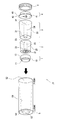
- FIG. 2 is a figure which shows the loading order of the component part for assembling the syringe 70.
- the power supply unit 1, the drive unit 2, the holding unit 3, and the nozzle unit 4, which are components of the syringe 70 are sequentially loaded in the housing 5 serving as a main body. These components are fixed to the housing 5 by the fixing ring 6 and assembled.
- the housing 5 is formed in a hollow shape so that the power supply unit 1, the drive unit 2, the holding unit 3, and the nozzle unit 4 can be loaded into the housing at one end side in the axial direction. Opening 52 is formed. On the other hand, on the other end side in the axial direction of the housing 5, an opening provided so that the top of the pushbutton switch 11 provided in the power supply unit 1 that is initially loaded in the housing 5 is exposed as will be described later. 53 is formed.
- the hollow portion in the housing 5 is formed as a tapered surface 50 having a continuous inner peripheral surface, and the radius of the tapered surface 50 (inner diameter of the housing 5) advances from the opening 53 to the loading opening 52. In other words, it is formed so as to increase along the axis of the housing 5.
- the opening 53 side of the housing 5 is referred to as an upstream side, and the loading opening 52 side is referred to as a downstream side. This is based on the direction of flow when the injection liquid 34 is ejected in a state where each component is loaded in the housing 5 and the syringe 70 is assembled.
- the power supply unit 1, the driving unit 2, the holding unit 3, and the nozzle unit 4 are provided as individually configured components that are independently formed. 1 are sequentially loaded into the interior of the device to form the loaded state shown in FIG.
- the power source unit 1 is a power source for supplying power to an igniter 22 provided in the driving unit 2 described later.
- the power of the battery held therein is used.
- An applied voltage is generated between the power supply side electrodes 12.
- the power supply side electrode 12 is formed as a pair of electrodes of a protruding first electrode located on the central axis of the syringe 70 (housing 5) and a protruding second electrode separated from the electrode by a predetermined distance. Is done.
- the drive part 2 has the gas generating agent 25 in the inside, and the pressure of the combustion gas generated when the gas generating agent 25 burns is used as the injection energy of the injection solution stored in the holding part 3 to be described later.
- a drive unit side electrode 21 corresponding to the power supply side electrode 12 of the power supply unit 1 is formed on the end face of the drive unit 2.
- the drive unit side electrode 21 is formed in a circular shape having a minute circular first electrode located on the central axis of the syringe 70 (housing 5) and a radius equal to the predetermined distance with the first electrode as a center.
- the second electrode is formed as a pair of electrodes.
- the drive unit side electrode 21 By forming the drive unit side electrode 21 in this way, the drive unit side electrode 21 regardless of the relative position of the power supply unit 1 with respect to the drive unit 2 (relative position in the rotation direction around the central axis of the syringe 70). And the power supply unit side electrode 12 can be favorably maintained.
- the drive unit side electrode 21 is connected to an igniter 22 provided in the drive unit 2.
- the igniter 22 is a known electric ignition device.
- a voltage is applied between the drive unit side electrodes 21 from the power supply unit 1
- a current flows, whereby the igniter provided in the igniter 22 is burned.
- a combustion product resulting from the combustion of the igniting agent flows toward the gas generating agent 25 arranged in the combustion chamber 24 adjacent to the igniter 22, and as a result, the combustion of the gas generating agent 25 in the combustion chamber 24.
- the combustion gas is rapidly generated by the combustion of the gas generating agent 25, whereby pressure is applied to the metal piston 23 provided adjacent to the combustion chamber 24, and the piston 23 is disposed downstream of the syringe 70. It will be promoted toward the side.
- the end of the combustion chamber 24 closed by the piston 23 on the side of the holding unit 3 serves as a driving unit side opening.
- the igniter used in the igniter 22 is preferably an explosive containing zirconium and potassium perchlorate (ZPP), an explosive containing titanium hydride and potassium perchlorate (THPP), titanium and potassium perchlorate.
- ZPP zirconium and potassium perchlorate
- THPP titanium hydride and potassium perchlorate
- TiPP gunpowder containing aluminum and potassium perchlorate
- APP gunpowder containing aluminum and bismuth oxide
- AMO aluminum and molybdenum oxide
- ACO gunpowder containing aluminum and copper oxide
- Explosives containing aluminum and iron oxide (AFO) or explosives composed of a combination of these explosives.
- These explosives generate high-temperature and high-pressure plasma at the time of combustion immediately after ignition, but exhibit a characteristic that the generated pressure rapidly decreases because the combustible organisms do not contain gas components when they become room temperature.
- the gas generating agent 25 disposed in the combustion chamber 24 is preferably a single base smokeless powder composed of 98% by mass of nitrocellulose, 0.8% by mass of diphenylamine and 1.2% by mass of potassium sulfate. It is also possible to use various gas generating agents that are used in gas generators for airbags and gas generators for seat belt pretensioners.
- the predetermined gas generated during combustion contains a gas component even at room temperature.
- the gas generating agent 25 is not necessarily used, and the drive unit 2 may be configured by the igniter 22 and the piston 23.
- the holding unit 3 accommodates an injection solution 34 that is an injection target substance to be injected by the syringe 70 therein.
- a through hole (accommodating hole) is provided at the center of the holding portion 3 so as to be along the central axis of the housing 5 in a state where the holding portion 3 is loaded in the housing 5 as shown in FIG. ) 33 is formed.
- the injection liquid 34 is accommodated in the space between the upstream stopper 31 and the downstream stopper 32.
- FIG. The upstream stopper 31 and the downstream stopper 32 allow the injection liquid 34 to smoothly flow into the through-hole 33 as the piston 23 slides, as will be described later, so that the injection liquid does not leak when the injection liquid 34 is accommodated.
- the nozzle part 4 has a flow path for injecting the injection solution 34 accommodated in the holding part 3 to an injection target (injection target region) outside the syringe 70.
- the nozzle portion 4 is formed with a nozzle 43 for injecting the injection solution 34, and the downstream stopper 32 in a state where the nozzle portion 4 is loaded in the housing 5 as shown in FIG. 1.
- a recessed portion 41 that can accommodate the downstream plug 32 is formed at a location facing the.
- the recess 41 has substantially the same diameter as the downstream plug 32 and has a depth slightly longer than the length of the downstream plug 32.
- the downstream stopper 32 can be accommodated in the recess 41 when pressure is applied to the injection solution 34 by the injection energy from the drive unit 2.
- the pressurized injection solution 34 is released from the space in the through hole 33 of the holding unit 3.
- a flow path 42 for guiding the opened injection solution 34 to the nozzle 43 is provided so as to extend in a direction perpendicular to the central axis of the syringe 70.
- the released injection solution 34 is ejected from the nozzle 43 to the injection target through the flow path 42.
- a plurality of nozzles 43 may be formed in the nozzle portion 4 or one nozzle 43 may be formed.
- the flow paths 42 corresponding to the nozzles 43 are formed so that the injection solution released to the nozzles 43 is fed.
- the nozzles 43 are arranged at equal intervals around the central axis of the syringe 70.
- the diameter of the nozzle 43 is appropriately set in consideration of the injection target, the injection pressure applied to the injection liquid 34, the physical properties (viscosity) of the injection liquid, and the like.
- the power supply unit 1, the drive unit 2, the holding unit 3, and the nozzle unit 4 are independently configured, and each component unit is mounted on the housing 5 as shown in FIG. By sequentially loading, the loading state shown in FIG. 1 is formed.
- the user can select components according to the purpose of injection and assemble them to assemble the final syringe 70.
- a plurality of types of driving units 2 with different types and amounts of the gas generating agent 25 can be prepared so that the pressure profile applied to the injection solution 34 can be changed to adjust the injection depth of the injection target. .
- the type and amount of the injection liquid 34 to be injected onto the injection target can be adjusted according to the state of the injection target (for example, the case where the injection target is an adult skin structure and the skin of a child Preparation of multiple types of holding portions 3 with different types and amounts of injection solutions, so that the dose can be adjusted considering that the amount of injection solution to be administered is different from that of a structure. can do.
- a plurality of types of nozzle portions 4 having different numbers of nozzles 43, nozzle diameters, and the like can be prepared so that a suitable injection form of the injection solution 34 can be selected according to the injection target.
- the user selects one drive unit 2, one holding unit 3, and one nozzle unit 4 in order to achieve a predetermined injection purpose performed by the user, and each configuration as shown in FIG.
- the part is loaded into the housing 5 through the loading opening 52 and the syringe 70 can be used.
- pouring of the injection solution according to various objectives is easily implement
- each component unit has its outer shape. It is preferable to attach a predetermined unified paint or design.
- the drive unit 2 is unified with blue paint
- the holding unit 3 is unified with yellow paint
- the nozzle unit 4 is unified with red paint, and the like. Thereby, user's mistakes, such as selecting the some drive part 2, can be suppressed.
- the power supply unit 1 is first loaded in the housing 5.
- the stepped portion 13 provided around the pushbutton switch 11 is replaced with the stepped portion provided around the opening 53 of the housing 5.
- the loading position of the power supply unit 1 is determined. In this loading position, the top surface of the pushbutton switch 11 and the end surface of the housing 5 on the opening 53 side are flush with each other.
- the drive unit 2 receives the applied voltage from the power supply unit 1, burns the gas generating agent 25, pressurizes the injection solution 34 with the generated combustion gas, and pressurizes the injection. Since the liquid 34 is ejected from the nozzle 43 to the outside, the order of loading the components into the housing 5 is as shown in FIG. 2, after the power supply unit 1, the drive unit 2, the holding unit 3, and the nozzle unit. Must be 4. If it is loaded in the wrong order, the injection solution 34 cannot be ejected by the syringe 70.
- the outer peripheral surface of each component is formed as a tapered surface (first tapered surface) so as to correspond to the tapered surface 50 (second tapered surface) which is the inner peripheral surface of the housing 5.
- first tapered surface the tapered surface
- second tapered surface the tapered surface 50
- the radius (outer diameter) forming the tapered surface 50 increases from the upstream side toward the downstream side.
- each component is formed so that the outer peripheral surface of the power supply unit 1, the drive unit 2, the holding unit 3, and the nozzle unit 4 forms a tapered surface (first tapered surface) so as to correspond to the tapered surface 50 on the housing 5 side.
- the outer peripheral surfaces 10, 20, 30, 40 are formed.
- the outer peripheral surfaces 10, 20, 30, 40 of the respective components are formed so as to have a continuous tapered surface when they are overlapped, so that the syringe 70 can be used.
- the loading position of each component is uniquely determined as shown in FIG. If the holding unit 3 is loaded into the housing 5 before the drive unit 2, the holding unit 3 is in a position where the outer peripheral surface 30 of the holding unit 3 and a part of the corresponding tapered surface 50 are in contact with each other, that is, holding. It is not possible to proceed deeper (upstream side) than the loading position where the unit 30 is to be loaded. Therefore, when the user tries to load the drive unit 2 thereafter, the drive unit 2 cannot be loaded, so that the user can quickly notice that the loading order is incorrect. Therefore, the taper surface 50 (second taper surface) of the housing 5 and the continuous taper surface (first taper surface) formed by overlapping the outer peripheral surfaces 10, 20, 30, and 40 of the respective components are provided in the present invention. Corresponds to the defining means.
- the fixing ring 6 is inserted into the housing 5 so as to come into contact with the end face of the nozzle portion 4 located on the most downstream side.
- the fixing ring 6 has a male screw cut on the outer periphery thereof, and is screwed with a female screw portion 51 provided in the vicinity of the end portion (loading opening 52) of the inner peripheral surface of the housing 5. Thereby, each component loaded in the housing 5 can be pressed and fixed via the nozzle portion 4.
- the power supply unit 1 is also loaded into the housing 5 through the loading opening 52 together with the other components.
- the power supply unit 1 may be loaded from the upstream side with respect to the housing 5.
- the stepped portion 14 is provided around the end surface opposite to the end surface where the push button switch 11 of the power supply unit 1 is provided.
- a recess 55 for accommodating the power supply unit 1 is provided on the opening 53 side of the housing 5, and protrudes into a space connecting the recess 55 and the space in the housing 5 defined by the tapered surface 50.
- a portion 56 is provided.
- the stepped portion 14 on the power supply unit 1 side is abutted against the protrusion 56 on the housing 5 side, so that the loading position of the power supply unit 1 is determined.
- the loaded power supply unit 1 is fixed to the housing 5 by a known fixing means or the like (for example, in a state where the power supply unit 1 has a snap fit or the like and is detachable from the housing).
- the power supply unit side electrode 12 is exposed toward the space in the housing 5 defined by the tapered surface 50, as in FIG. Then, the drive unit 2 can be brought into contact with the drive unit side electrode 21 of the drive unit 2 loaded through the loading opening 52.
- the power supply unit 1 can execute power supply to the drive unit 2 several times depending on the storage capacity. In such a case, as shown in FIG. 1, as with other components such as the drive unit 2, it may be troublesome to load the power supply unit 1 into the housing 5 each time the injection solution 34 is injected. is there. Therefore, as shown in FIG. 3, only the power supply unit 1 is loaded separately from the other components, in other words, the power supply unit 1 is not subject to the regulation of the loading position by the tapered surfaces described above. Thereby, the troublesomeness regarding the loading of the power supply unit 1 can be reduced. It should be noted that after supplying power a predetermined number of times according to the storage capacity of the power supply unit 1, the power supply unit 1 may be removed from the housing and a new power supply unit 1 may be loaded.
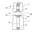
- FIG. 4 shows a relative relationship between the drive unit 2 and the holding unit 3 according to this modification.
- a gas generating agent 25 is disposed in the combustion chamber 24.
- the gas generating agent 25 is combusted by ignition of the igniter 22, and the piston 23 is pressed by the combustion gas.
- the piston 23 moves from the opening part (driving part side opening part) 24a on the driving part 3 side of the combustion chamber 24 to the holding part 3 side.
- the piston 23 enters through the end portion (receiving hole side end portion) 33a of the through hole 33 in which the upstream plug 31, the injection solution 34, and the downstream plug 32 are arranged.
- the injection energy of the gas generating agent 25 from the combustion gas is transmitted to the injection solution 34 via the upstream plug 31.
- annular protrusion 26 is provided on the end surface of the driving unit 2 on the holding unit 3 side so as to surround the opening 24a.
- the annular protrusion 26 is formed of a relatively soft metal such as aluminum.
- FIG. 5 shows a relative relationship between the drive unit 2 and the holding unit 3 according to this modification.
- annular protrusion 27 and an annular groove 28 are provided so that effective injection energy can be transmitted to the injection solution 34 in the same manner.
- the structure to perform is disclosed. Specifically, an annular protrusion 27 is provided on the end surface of the driving unit 2 on the holding unit 3 side so as to surround the opening 24a. Unlike the annular protrusion 26, the annular protrusion 27 is not deformed when fixed on the housing 5, and is provided so as to surround the end 33a on the end face of the holding part 3 on the drive part 2 side.
- the annular groove 28 is fitted. The depth of the annular groove 28 is set slightly deeper than the height of the annular protrusion 27.
- the second embodiment of the syringe 70 will be described, in particular, the defining means for defining the loading position of each component loaded in the housing 5.
- the configuration other than the defining means is the same as that of the syringe 70 according to the first embodiment. Therefore, the same reference numerals are assigned to the same configuration. Therefore, the detailed description is abbreviate
- the power supply unit 1, the drive unit 2, the holding unit 3, and the nozzle unit 4 loaded in the housing 5 are formed in a substantially cylindrical shape, and the radius (outer diameter) of the outer peripheral surface of each component unit is
- the outer peripheral surface 100 of the power supply unit 1, the outer peripheral surface 200 of the driving unit 2, the outer peripheral surface 300 of the holding unit 3, and the outer peripheral surface 400 of the nozzle unit 4 are designed to increase in this order. Therefore, in the case of the present embodiment, when the respective constituent portions are overlapped in the housing 5, the outer peripheral surface of each constituent portion does not form a continuous tapered surface as in the first embodiment, but is stepped. A discontinuous outer peripheral surface is formed.
- the inner peripheral surface on the housing 5 side is formed corresponding to the outer peripheral surface of each component.
- an inner peripheral surface 501 is provided corresponding to the outer peripheral surface 100 of the power supply unit 1
- an inner peripheral surface 502 is provided corresponding to the outer peripheral surface 200 of the drive unit 2
- the outer peripheral surface 300 of the holding unit 3 is provided corresponding to the outer peripheral surface 400 of the nozzle portion 4.
- the respective radii are set larger in the order of the inner peripheral surfaces 501, 502, 503, and 504. Therefore, the inner peripheral surface of the housing 5 is also formed as a stepped discontinuous surface.
- the outer peripheral surfaces 100, 200, 300, and 400 of the respective components are formed so as to be stepped discontinuous outer peripheral surfaces when they are overlapped, and the inner peripheral surface of the housing 5 is the outer peripheral surface.
- the loading position of each component in the housing 5 is uniquely determined as shown in FIG. .
- the stepped inner peripheral surfaces 501, 502, 503, and 504 on the housing 5 side and the stepped outer peripheral surfaces formed by overlapping the outer peripheral surfaces 100, 200, 300, and 400 of the respective components are provided in the present invention. Corresponds to the defining means.
- each component may be a truncated cone shape so that the outer peripheral surface becomes a tapered surface instead of the above-described columnar shape.
- the cells to be injected and the cultured cells in the scaffold tissue / scaffold It is possible to seed stem cells and the like.
- the cells to be injected in addition to the case where the above-mentioned injection solution is injected into the skin structure, for example, in the field of regenerative medicine for humans, the cells to be injected and the cultured cells in the scaffold tissue / scaffold It is possible to seed stem cells and the like.
- cells that can be appropriately determined by those skilled in the art depending on the site to be transplanted and the purpose of recellularization such as endothelial cells, endothelial precursor cells, bone marrow cells, prebones Blast cells, chondrocytes, fibroblasts, skin cells, muscle cells, liver cells, kidney cells, intestinal cells, stem cells, and any other cells considered in the field of regenerative medicine can be injected by the syringe 70. . More specifically, the liquid (cell suspension) containing the cells to be seeded is accommodated in the holding unit 3 and pressurized by the combustion of the gas generating agent 25 to thereby give a predetermined site to the transplanted site. Cells are injected and transplanted.
- the syringe 70 according to the present invention can also be used for delivery of DNA or the like to cells, scaffold tissues, scaffolds, etc. as described in JP-T-2007-525192.
- the use of the syringe 70 according to the present invention is more preferable than the case where delivery is performed using a needle because the influence on the cells, the scaffold tissue, the scaffold, and the like can be suppressed.
- the syringe 70 according to the present invention is suitable also when various genes, tumor suppressor cells, lipid envelopes, etc. are directly delivered to a target tissue or when an antigen gene is administered to enhance immunity against a pathogen. Used for.
- various disease treatment fields fields described in JP 2008-508881, JP 2010-503616, etc.
- immunomedical fields fields described in JP 2005-523679, etc.
- the syringe 70 can be used, and the field in which the syringe 70 can be used is not intentionally limited.
Landscapes
- Health & Medical Sciences (AREA)
- Engineering & Computer Science (AREA)
- Hematology (AREA)
- Anesthesiology (AREA)
- Biomedical Technology (AREA)
- Heart & Thoracic Surgery (AREA)
- Vascular Medicine (AREA)
- Life Sciences & Earth Sciences (AREA)
- Animal Behavior & Ethology (AREA)
- General Health & Medical Sciences (AREA)
- Public Health (AREA)
- Veterinary Medicine (AREA)
- Bioinformatics & Cheminformatics (AREA)
- Pharmacology & Pharmacy (AREA)
- Infusion, Injection, And Reservoir Apparatuses (AREA)
Description
本発明は、注射目的物質を生体の注射対象領域に注射する注射器に関する。
注射針を介することなく注射を行う無針注射器では、一般に、火薬、加圧ガス、バネ等により薬剤等を含む注射液に対して圧力を加えることで注射成分の射出が行われる構成が採用される。そして、注射液を生体内の所望の領域に送り込めるよう、注射液に掛けられる加圧力が調整されることになる。ここで、特許文献1に示す技術では、加圧を行うためのガス発生剤と注射液とを一つのユニットに形成し、当該ユニットを注射器本体に装填して使用する構成が開示されている。当該構成では、注射器本体に挿入されたユニットは、それを覆う蓋が閉じられて、使用準備状態に至る。そして、使用後は新しいユニットを装填することで、次の注射が可能となる。
また、特許文献2では、注射液を保持する部分と、その注射液に対して圧力を加える加圧部分とを独立させた構成が開示されている。当該構成では、注射液の射出後、注射液を保持する部分と、加圧部分の動力源とをそれぞれ交換することで、次の注射が可能となる。
注射針の有無にかかわらず、注射液をその注射対象に注射する場合、その注射対象者や注射目的に応じて、注射液の種類や量、また、注射液を目的とする部位に送り届けるために該注射液に対してかけるべき荷重の大きさ等、注射に関する条件が変動する。そのため、目的とする条件での注射を実現するために、注射器の構成を当該条件に応じたものとする必要があり、ユーザの利便性が必ずしも良いものとは限らない。
本発明では、上記した問題に鑑み、様々な目的に応じた注射液の射出を容易に実現するとともに、ユーザの利便性を向上させた注射器を提供することを目的とする。
上記課題を解決するために、本発明は、注射器のハウジングに装填される、該注射器の構成部の並びを規定するための構成を注射器に備えることとした。このような構成を採用することで、注射を行うために注射器に各構成部を装填した場合、仮に構成部の装填順序を間違ったとしても、当該規定するための構成によってユーザがその誤りを早期に認識することができるため、注射器の利便性を向上させることが可能となる。
具体的には、本発明は、生体の注射対象領域に注射目的物質を注射する注射器であって、ハウジングと、注射目的物質を収容する保持部と、前記保持部に収容されている前記注射目的物質に対して、該保持部からの射出のためのエネルギーを付与する駆動部と、前記保持部から射出された前記注射目的物質が流れる流路を含み、該流路の開口端から注射対象領域に対して該注射目的物質を射出するノズル部と、を備える。そして、前記ハウジングに対して、前記保持部、前記駆動部、前記ノズル部が、それぞれ独立して装填されることで、前記注射目的物質の射出が可能な状態が形成される。更に、前記注射器は、前記注射目的物質の射出のために前記ハウジング内に前記保持部および前記駆動部が常に同一の並びで装填される装填状態が形成されるように、該ハウジングに対する、該保持部および該駆動部の装填位置を規定する規定手段を、備える。
本発明に係る注射器は、その構成部である保持部、駆動部、ノズル部がそれぞれ独立してハウジングに装填されることで、注射目的物質の射出準備が行われるものである。そして、当該注射器では、保持部に収容されている注射目的物質に対して駆動部によって射出エネルギーが加えられることで、ノズル部の流路を注射目的物質が流れ、該流路の開口端から注射対象領域に対して射出される。この注射目的物質は、注射対象領域の内部で効能が期待される成分を含むものであり、上記のように駆動部により加えられる射出エネルギーがその射出時の駆動源である。そのため、駆動部による射出が可能であれば、注射目的物質の注射器内の収容状態や、液体やゲル状等の流体、粉体、粒状の固体等の注射目的物質の具体的な物理的形態は問われない。
たとえば、注射目的物質は液体であり、また固体であっても射出を可能とする流動性が担保されればゲル状の固体であってもよい。更には、注射目的物質は、粉体の状態であってもよい。そして、注射目的物質には、生体の注射対象領域に送り込むべき成分が含まれ、当該成分は注射目的物質の内部に溶解した状態で存在してもよく、又は当該成分が溶解せずに単に混合された状態であってもよい。一例を挙げれば、送りこむべき成分として、抗体増強のためのワクチン、美容のためのタンパク質、毛髪再生用の培養細胞等があり、これらが射出可能となるように、液体、ゲル状等の流体に含まれることで注射目的物質が形成される。
また、駆動部による注射目的物質への射出エネルギーの付与態様は、注射目的物質の射出が可能であれば、様々なエネルギー源を利用することができる。たとえば、火薬の燃焼で発生するガスの圧力を利用したもの、加圧のための電気的アクチュエータ(モータやピエゾ素子等)を利用したものが、射出のためのエネルギー源として挙げられる。
ここで、本発明に係る注射器を使って生体に注射目的物質を供給するときには、当該生体の大きさ、年齢、性別などの個体差があり、発現させる効果の違いによって使用される注射目的物質の種類も異なる。また注射対象領域によっても表皮、皮内、皮下、筋肉層などの生体組織における各層の厚さも異なり、それぞれの深さに注射目的物質を到達させるためには、当該注射目的物質に加えるべき荷重も調整する必要がある。そこで、当該注射器においては、注射目的物質を収容する保持部と、そこに収容されている注射目的物質に対して射出エネルギーを付与する駆動部と、注射目的物質の射出が行われるための流路を有するノズル部とが、それぞれ独立して構成されるとともに、それぞれがハウジングに対して独立して装填される。
すなわち、注射目的物質を収容する上記保持部においては、その注射目的物質の種類や量を複数準備しておき、また上記駆動部においては、注射目的物質に射出エネルギーを供給するためのエネルギー源として複数の形態を準備しておき、注射目的に応じてそれらを組み合わせて注射器のハウジングに組み込んで使用される。更に、ノズル部についても複数の態様を準備して上記組み合わせに含めることで、注射目的物質の射出の態様(例えば、注射対象領域に対して複数箇所で注射を行う、射出された注射目的物質の流れの直径をどの程度にするか等)も、調整しやすくなる。このように、注射器の各構成部を注射目的に応じて適宜組み合わせることを可能とすることで、本発明に係る注射器では有用性、利便性が向上する。
ここで、複数種類の駆動部とは、例えばエネルギー源が火薬やガス発生剤の場合、その量、形状、寸法などが異なるものを複数存在させることであり、加圧ガスをエネルギー源とする場合は、当該ガスの充填量を異ならせることである。さらにエネルギー源がバネである場合、そのばね定数が異なるものを複数存在させることである。また複数の保持部とは、充填される注射目的物質の種類や量などが異なるものが複数存在することを意味する。
そして、保持部と駆動部、更にはノズル部を適宜組み合わせてハウジングに対して装填されることで、上記のような注射目的に応じた注射目的物質の多様な射出を容易に実現することができるが、一方で、ハウジングに対する各構成部の装填順序を誤ると注射器が正常に機能しない場合がある。そのような場合には、ユーザが直ちに装填順序の誤りを認識できることが好ましく、それにより注射器の利便性を高めることになる。また、各構成部の装填順序を正しく行うことで、注射器の安定した性能発現につながり、再現性のよい注射が達成できるため好ましいとも言える。
そこで、本発明に係る注射器では、ハウジングに対する、少なくとも保持部と駆動部の装填位置を規定する規定手段が備えられる。保持部と駆動部がハウジングに装填される場合、駆動部から供給される射出エネルギーが、保持部に収容される注射目的物質に付与されることで、その射出が実現されるという構成を踏まえ、ハウジングに対する保持部および駆動部の装填位置は所定の位置とされている。したがって、この所定の位置と異なる位置に保持部等が装填されてしまうと、注射器による注射目的物質の射出が好適に行うことができなくなる。しかし、本発明に係る注射器では、上記規定手段により、ハウジングに対する保持部等の装填位置が一義的に規定されることになるため、換言すれば、保持部や駆動部が、規定されている装填位置以外の位置においてハウジング内に装填された状態とはならないため、仮に保持部等の装填順序を誤ると、ユーザはその誤りを直ちに認識することが可能となる。これにより、各構成部を適宜組み合わせることによる多様な注射態様の実現を、ユーザの利便性を損なうことなく実現することが可能となる。
なお、上記保持部は、一度使用した後は廃棄し、新たな保持部を組み込んで注射を行うようにしてもよい。このとき、駆動部およびノズル部も1回限りの使用とし、使用後は新たな駆動部等を使用してもよい。あるいは、駆動部およびノズル部は繰り返し使用できるものであれば、繰り返し、もしくは数回連続して使用してもよい。なお、注射器のハウジングは基本的には繰り返し使用でき、このため注射目的にあわせて複数のハウジングを所有する必要が無く、注射器の構成部品の管理が容易となる。
また、規定手段によって装填位置が規定される保持部および駆動部については、保持部と駆動部がハウジング内に装填される前に、例えば粘着テープや糊などによって互いに仮止めをした状態でハウジングに装填してもよい。あるいは、保持部と駆動部を個別にハウジング内部に装填してもよい。また、規定手段によって装填位置が規定されるものとして、ノズル部を含めてもよい。ノズル部の場合、注射目的物質を射出する流路が含まれることから、ユーザにおいても比較的装填順序を間違えにくいと考えられるが、本発明においては、上記の通り、ノズル部の装填位置も規定手段によって規定されることを排除するものではない。
ここで、上記注射器において、前記駆動部は、電源部からの印加電圧により燃焼する火薬又はガス発生剤を含み、該火薬又は該ガス発生剤の燃焼で生成される燃焼ガスの圧力を介して、前記注射目的物質に射出エネルギーを付与するように構成してもよい。その場合、前記規定手段は、前記注射目的物質の射出のために前記ハウジング内に前記電源部、前記保持部、前記駆動部が常に同一の並びで装填される装填状態が形成されるように、該ハウジングに対する、該電源部、該保持部、該駆動部の装填位置を規定してもよい。すなわち、電源部を含めて、規定手段によってハウジングに対する各構成部の装填位置が規定されることで、各構成部を適宜組み合わせることによる多様な注射態様の実現を、ユーザの利便性を損なうことなく実現することが可能となる。
上記の態様では、電源部の装填位置が規定手段によって規定されていたが、それに代えて、当該電源部の装填位置は、規定手段によって規定されないようにしてもよい。すなわち、注射器に上記電源部を備える場合であって、前記規定手段は、前記注射目的物質の射出のために前記ハウジング内に前記保持部、前記駆動部が常に同一の並びで装填される装填状態が形成されるように、該ハウジングに対する、該保持部、該駆動部の装填位置を規定し、一方で、前記電源部は、前記ハウジングへの装填において、前記規定手段による装填位置の規定は行われないようにしてもよい。電源部が有する蓄電容量次第では、複数回にわたって駆動部に対して火薬等の燃焼に要する電圧印加が可能な場合がある。そのような場合には、注射目的物質の射出ごとに電源部をハウジングから取り外す必要はないため、規定手段による装填位置の規定の対象に含める必要はない。また蓄電容量次第では、駆動部や保持部とは独立して電源部をハウジングから取り出し可能になっているほうが、交換等における利便性が向上する。
ここで、上述までの注射器での前記ハウジングへの装填において、前記駆動部、前記保持部、前記ノズル部が該ハウジングの軸方向に重ねあわされて形成されるとともに、該ハウジングには、その開口部を介して該駆動部、該保持部、該ノズル部が順に一方向から装填されるように構成してもよい。その場合、前記規定手段は、前記駆動部、前記保持部、前記ノズル部が重ねあわされたときに前記駆動部から前記保持部にかけて形成される連続した外周面であって、前記駆動部から前記保持部に向かうに従い、該連続した外周面の半径が増大するように形成された、第一テーパ面と、前記ハウジング側の連続した内周面であって、前記第一テーパ面に対応する、第二テーパ面と、を有する。
すなわち、駆動部、保持部、ノズル部が重ねあわされることで形成される構成物側に設けられる第一テーパ面と、それに対応する該構成物が装填されるハウジング側に設けられる第二テーパ面とで、規定手段が形成される。これらのテーパ面の半径は、ハウジングの内部において当該構成物が装填される開口部に向かうに従い増大するように形成されている。そのため、相対的には、駆動部、保持部、ノズル部の順で、その半径が大きくなるため、仮に保持部やノズル部を駆動部よりも先にハウジングに装填しようとすると、ノズル部の装填位置よりも奥に、該ノズル部は進入することはできないため、結果として駆動部を装填することができなくなり、以てユーザは、注射器の構成部の装填順序を誤ったことを直ちに認識することができる。
また、上記のようにテーパ面を利用する形態に代えて、規定手段が、前記駆動部の外周面と、該駆動部の外周面の半径より大きい半径を有する、前記保持部の外周面とを含んで段状に形成される第一外周面と、前記ハウジング側に段状に形成される内周面であって、前記第一外周面に対応する、第二内周面と、を有するように構成されてもよい。このように、半径の異なる段状の外周面および内周面、換言すると、駆動部と保持部とでは連続しない外周面およびそれに対応するハウジングの内周面を利用することで、駆動部および保持部の装填位置を規定することが可能である。なお上記の発明においては、駆動部および保持部はハウジングに対して同軸上に配置されることができ、さらに電源部やノズル部も同軸上に配置されるようにすることができる。
この他、ハウジングへの装填において、仮にある構成部の装填順序を誤った場合、その構成部が本来装填される装填位置に至ることで、別の構成部の装填が阻害されるように構成され、ユーザに装填順序の誤りを認識させることが可能であれば、別の具体的な態様の規定手段も、本発明に係る注射器に採用してもよい。
ここで、上述までの注射器において、前記駆動部は、前記射出エネルギーを前記保持部側に付与するための開口部である駆動部側開口部を有し、前記保持部は、前記注射目的物質を収容する収容孔を有するとともに、該収容孔は、前記駆動部側開口部から付与される前記射出エネルギーを受ける収容孔側端部を有するように構成してもよい。その場合、前記駆動部側開口部もしくは前記収容孔側端部を囲む環状の突起部であって、前記装填状態において該環状の突起部が変形することで、該駆動部側開口部と該収容孔側端部との間の空間を密封する環状突起部が、前記駆動部側もしくは前記保持部側の何れか一方に設けられる。または、別法として、前記駆動部側開口部もしくは前記収容孔側端部を囲む環状の溝であって、前記装填状態において前記環状の突起部が嵌まり込むことで、該駆動部側開口部と該収容孔側端部との間の空間を密封する環状の溝部が、前記駆動部側もしくは前記保持部側の他方に設けられる。
駆動部の駆動部側開口部から放たれた射出エネルギーは、保持部の収容孔側端部に伝えられることで、収容孔に収容されている注射目的物質への射出エネルギーの付与が行われることになる。ここで、上述までの通り、本発明に係る注射器では、駆動部と保持部がそれぞれ独立して構成され、そしてハウジングへ装填される。そのため、駆動部と保持部との間での上記射出エネルギーの付与が好適に行われなければ、注射目的物質の注射対象領域への射出が良好に行われないことになる。そこで、上記の通り、駆動部側もしくは保持部側に変形可能な環状の突起部を設けることで、又は、駆動部側と保持部側に、互いに嵌合する環状の突起部と環状の溝部をそれぞれ設けることで、駆動部側開口部と収容孔側端部との間の空間での密封性を高め、駆動部側から伝えられる射出エネルギーが外部に漏れ出すのを可及的に抑制することが可能となる。これにより、注射目的物質の注射対象領域への射出を良好に行い得る。
様々な目的に応じた注射液の射出を容易に実現するとともに、ユーザの利便性を向上させた注射器を提供することが可能となる。
以下に、図面を参照して本発明の実施形態に係る注射器70について説明する。なお、本発明の実施例に係る注射器70は、いわゆる注射針を有していない無針注射器であるが、本発明の趣旨が変わらない範囲においては、注射針の有無にかかわらず本発明を適用することが可能である。また、以下の実施形態の構成は例示であり、本発明はこの実施の形態の構成に限定されるものではない。
図1は、本発明に係る注射器70において、組み立てが概ね完了した状態における、注射器70の概略構成を示す断面図である。また、図2は、注射器70を組み立てるための、その構成部の装填順序を示す図である。注射器70は、図2に示すように、その本体となるハウジング5の内部に、注射器70の構成部である、電源部1、駆動部2、保持部3、ノズル部4が順次装填され、最後に固定リング6によって、これらの構成部がハウジング5に対して固定され、組み立てられることになる。
詳細には、ハウジング5は、その内部が中空状に形成され、軸方向の一端側に、電源部1、駆動部2、保持部3、ノズル部4がハウジング内に装填可能となるように装填用開口部52が形成されている。一方で、ハウジング5の軸方向の他端側には、後述するようにハウジング5に最初に装填される電源部1に設けられた押ボタンスイッチ11の頂部が露呈するように設けられた開口部53が形成されている。そして、ハウジング5内の中空部分は、その内周面が連続したテーパ面50として形成され、テーパ面50の半径(ハウジング5の内径)は、開口部53から装填用開口部52に進むに従い、換言すれば、ハウジング5の軸に沿ってその増大するように形成されている。なお、本実施例では、注射器70において、ハウジング5の開口部53側を上流側と称し、装填用開口部52側を下流側と称する。これは、各構成部がハウジング5に装填され注射器70が組み立て完了となった状態において、注射液34が射出されるときの流れの方向に基づいたものである。
ここで、注射器70においては、個別に機能を有し、独立して形成される構成部として、電源部1、駆動部2、保持部3、ノズル部4が、ハウジング5の装填用開口部52を介して、順次その内部に装填されて、図1に示す装填状態が形成される。電源部1は、後述する駆動部2に設けられた点火器22に電力供給を行うための電源であり、ユーザが押ボタンスイッチ11を押下すると、内部に保有するバッテリの電力を利用して、電源側電極12間に印加電圧を発生させる。この電源側電極12は、注射器70(ハウジング5)の中心軸上に位置する突起状の第一電極と、当該電極から所定の距離だけ離れた突起状の第二電極との一対の電極として形成される。
次に、駆動部2は、その内部にガス発生剤25を有し、ガス発生剤25が燃焼することで生じる燃焼ガスの圧力を、後述する保持部3に収容される注射液の射出エネルギーとして付与する。具体的には、電源部1の電源側電極12に対応する駆動部側電極21が、駆動部2の端面に形成されている。この駆動部側電極21は、注射器70(ハウジング5)の中心軸上に位置する微小円形の第一電極と、当該第一電極を中心として上記所定の距離と同じ半径を有する円周形状に形成された第二電極との一対の電極として形成される。このように駆動部側電極21が形成されることで、駆動部2に対する電源部1の相対位置(注射器70の中心軸を中心とする回転方向の相対位置)を問わず、駆動部側電極21と電源部側電極12との接触を良好に維持することができる。
そして、駆動部側電極21は、駆動部2内に設けられた点火器22に接続されている。点火器22は、公知の電気式の点火装置である。駆動部側電極21間に電源部1から電圧印加されると電流が流れ、それにより点火器22内に設けられた点火薬が燃焼する。このとき、点火薬の燃焼による燃焼生成物は、点火器22に隣接する燃焼室24に配置されているガス発生剤25側へと流れ込み、その結果、燃焼室24内でガス発生剤25の燃焼が開始される。そして、ガス発生剤25の燃焼により燃焼ガスが急激に発生することで、燃焼室24に隣接して設けられた金属製のピストン23に対して圧力が付与され、ピストン23が、注射器70の下流側に向かって推進していくことになる。図1ではピストン23で閉塞されている燃焼室24の保持部3側端部が駆動部側開口部となる。
なお、点火器22において用いられる点火薬として、好ましくは、ジルコニウムと過塩素酸カリウムを含む火薬(ZPP)、水素化チタンと過塩素酸カリウムを含む火薬(THPP)、チタンと過塩素酸カリウムを含む火薬(TiPP)、アルミニウムと過塩素酸カリウムを含む火薬(APP)、アルミニウムと酸化ビスマスを含む火薬(ABO)、アルミニウムと酸化モリブデンを含む火薬(AMO)、アルミニウムと酸化銅を含む火薬(ACO)、アルミニウムと酸化鉄を含む火薬(AFO)、もしくはこれらの火薬のうちの複数の組合せからなる火薬が挙げられる。これらの火薬は、点火直後の燃焼時には高温高圧のプラズマを発生させるが、常温となり燃焼性生物が凝縮すると気体成分を含まないために発生圧力が急激に低下する特性を示す。
また、燃焼室24内に配置されるガス発生剤25としては、好ましくは、ニトロセルロース98質量%、ジフェニルアミン0.8質量%、硫酸カリウム1.2質量%からなるシングルベース無煙火薬が挙げられる。また、エアバッグ用ガス発生器やシートベルトプリテンショナ用ガス発生器に使用されている各種ガス発生剤を用いることも可能である。このガス発生剤25は、上記点火薬と異なり、燃焼時に発生した所定のガスは常温においても気体成分を含む。なお、ガス発生剤25は必ずしも使用しなくてもよく、点火器22とピストン23とで駆動部2が構成されていてもよい。
次に、保持部3は、注射器70によって注射される注射目的物質である注射液34を、その内部に収容する。具体的には、保持部3の中央には、該保持部3が図1に示すようにハウジング5内に装填された状態において、ハウジング5の中心軸上に沿うように、貫通孔(収容孔)33が形成されている。そして、この貫通孔33において、上流栓31と下流栓32との間の空間に、注射液34が収容されている。そして、上流栓31および下流栓32は、注射液34の収容時に該注射液が漏れ出さないように、且つ後述するようにピストン23の摺動に伴って注射液34が円滑に貫通孔33内を移動できるように、表面にシリコンオイルを薄く塗布したゴム製のものである。そして上流線31で閉塞されている貫通孔(収容孔)33の駆動部2側端部が収容孔側端部となる。
次に、ノズル部4は、保持部3が収容している注射液34を、注射器70の外部の注射対象物(注射対象領域)に射出するための流路を有している。具体的には、ノズル部4には、注射液34を射出するためのノズル43が形成されるとともに、図1に示すようにノズル部4がハウジング5内に装填された状態において、下流栓32と対向する箇所に、下流栓32を収容可能な凹部41が形成されている。この凹部41は、下流栓32とほぼ同じ径を有し、下流栓32の長さより若干長い深さを有する。これにより、駆動部2からの射出エネルギーで注射液34に圧力が掛かったときに、下流栓32が凹部41内に収容されることが可能となる。凹部41に下流栓32が収容されると、加圧された注射液34は、保持部3の貫通孔33内の空間から解放されることになる。その開放された注射液34を、ノズル43まで導くための流路42が、注射器70の中心軸に垂直な方向に延在するように設けられている。これにより、解放された注射液34は、流路42を経てノズル43から注射対象物へ射出されることになる。また、凹部41が下流栓32を収容する深さを有することで、注射液34の射出が下流栓32によって阻害されることを回避できる。
なお、ノズル43は、ノズル部4に複数形成されてもよく、または、一つ形成されてもよい。複数のノズル43が形成される場合には、各ノズル43に対して解放された注射液が送り込まれるように、各ノズル43に対応する流路42が形成される。さらに、複数のノズル43が形成される場合には、注射器70の中心軸の周囲に等間隔で各ノズル43が配置されるのが好ましい。また、ノズル43の径は、注射対象物、注射液34に掛かる射出圧力、注射液の物性(粘性)等を考慮して適宜設定される。
上述までのように、注射器70においては、電源部1、駆動部2、保持部3、ノズル部4が、それぞれ独立して構成され、各構成部が、図2に示すように、ハウジング5に対して順次装填されることで、図1に示す装填状態が形成されることになる。
このように、注射器70の構成部を、それぞれ独立して構成することで、ユーザは、注射目的に応じた構成部を選択して、それらを組み合わせて最終的な注射器70を組み立てることができる。例えば、注射液34に掛ける圧力プロファイルを変えて、注射対象物における注射深さを調整できるように、ガス発生剤25の種類や量を異ならせた複数種類の駆動部2を準備することができる。また、注射対象物に射出する注射液34の種類や量を、その注射対象物の状態等に応じて調整できるように(例えば、注射対象物が大人の皮膚構造体である場合と子供の皮膚構造体である場合とでは、投与すべき注射液の量も異なる点を踏まえて、その投与量を調整できるように)、注射液の種類や量を異ならせた複数種類の保持部3を準備することができる。また、注射対象物に応じた好適な注射液34の射出形態を選択できるように、ノズル43の数やそのノズル径等を異ならせた複数種類のノズル部4を準備することができる。そして、ユーザは、自己が行う所定の注射目的を達成するために、一つの駆動部2と、一つの保持部3と、一つのノズル部4とを選択し、図2に示すように各構成部を装填用開口部52を介して、ハウジング5に装填し注射器70が使用できる状態に至らせる。これにより、様々な目的に応じた注射液の射出が容易に実現される。
なお、ユーザが、ハウジングに対して、注射準備を行うために一つの駆動部2と、一つの保持部3と、一つのノズル部4とを選択しやすいように、各構成部は、その外形を所定の統一した塗装やデザインを付すのが好ましい。例えば、駆動部2は青色の塗装で統一し、保持部3は黄色の塗装で統一し、ノズル部4は赤色の塗装で統一する等である。これにより、複数の駆動部2を選択してしまう等のユーザのミスを抑制することができる。
ところで、図1、図2に示すように、ハウジング5に最初に装填されるのは電源部1である。電源部1が、押ボタンスイッチ11の面からハウジング5内に装填されると、押ボタンスイッチ11の周囲に設けられた段部13が、ハウジング5の開口部53の周囲に設けられた段部54に突き当てられて、電源部1の装填位置が決定される。この装填位置において、押ボタンスイッチ11の頂面と、ハウジング5の開口部53側の端面が面一の状態となる。
ここで、注射器70においては、電源部1からの印加電圧を駆動部2が受けて、ガス発生剤25を燃焼させ、それにより生じた燃焼ガスで注射液34を加圧し、加圧された注射液34をノズル43から外部に射出するという構成から、ハウジング5への各構成部の装填順序は、図2に示すように、電源部1の後は、駆動部2、保持部3、ノズル部4でなければならない。仮にこの順序を間違えて装填してしまうと、注射器70によって注射液34を射出することができない。
そこで、注射器70においては、各構成部のハウジング5への装填順序が適正なものとなるように、換言すれば、仮にユーザが各構成部の装填順序を誤った場合には、直ちにユーザがその誤りを認識できるように、ハウジング5内での各構成部の装填位置を規定するための構成が採用されている。具体的には、ハウジング5の内周面であるテーパ面50(第二テーパ面)に対応するように、各構成部の外周面がテーパ面(第一テーパ面)として形成されている。上記の通り、テーパ面50については、上流側から下流側に向けて、テーパ面50を形成する半径(外径)が増大するようになっている。そして、このテーパ面50に対応するように、ハウジング50に装填されるべき順序に従って、換言すれば、図1のように各構成部がハウジング5内でその軸方向に重ねあわされた状態で、ハウジング5側のテーパ面50に対応するように電源部1、駆動部2、保持部3、ノズル部4の外周面が連続したテーパ面(第一テーパ面)を形成するように、各構成部の外周面10、20、30、40が形成される。
このように各構成部の外周面10、20、30、40が、重ね合わされたときに連続したテーパ面となるように形成されることで、注射器70を使用できる状態にするためには、ハウジング5内での各構成部の装填位置が、図1に示すように一義的に決定されることになる。仮に、駆動部2より先に保持部3をハウジング5に装填してしまうと、保持部3は、自己の外周面30と、それに対応するテーパ面50の一部とが接触する位置、すなわち保持部30が装填されるべき装填位置よりも奥(上流側)には進むことができない。そのため、その後にユーザが駆動部2を装填しようとしたときに、駆動部2が装填できない状態となっているため、ユーザは装填順序を誤っていることに速やかに気付くことができる。したがって、ハウジング5のテーパ面50(第二テーパ面)と、各構成部の外周面10、20、30、40が重ね合わされて形成される連続したテーパ面(第一テーパ面)が、本発明に係る規定手段に相当する。
そして、図1に示すように各構成部がハウジング5内に装填されると、最も下流側に位置するノズル部4の端面に接触するように、固定リング6をハウジング5内に挿入する。固定リング6が、その外周に雄ネジが切ってあり、ハウジング5の内周面の端部(装填用開口部52)近傍に設けられた雌ネジ部51と螺合する。これにより、ノズル部4を介して、ハウジング5内に装填されている各構成部を押圧し、固定することができる。
<変形例1>
上記実施例では、電源部1も、他の構成部とともに、装填用開口部52を介してハウジング5内に装填されたが、その形態に代えて、図3に示すように、駆動部2等とは別に電源部1はハウジング5に対して上流側から装填するようにしてもよい。このとき、電源部1の押ボタンスイッチ11が設けられている端面とは反対側の端面の周囲に段部14が設けられる。そして、ハウジング5の開口部53側には、電源部1が収容される凹部55が設けられるとともに、この凹部55と、テーパ面50で画定されるハウジング5内の空間とを連結する空間に突部56が設けられる。そして、凹部55に電源部1が装填されると、電源部1側の段部14が、ハウジング5側の突部56に突き当てられることで、電源部1の装填位置が決まることになる。なお、装填された電源部1は、公知の固定手段等(例えば電源部1が有するスナップフィットなどで、ハウジングに対して着脱可能な状態で)でハウジング5に固定される。このようにハウジング5に電源部1が装填されると、電源部側電極12が、テーパ面50で画定されるハウジング5内の空間に向けて露呈された状態になり、図1と同じように、装填用開口部52を介して装填された駆動部2の駆動部側電極21と接触可能な状態となる。
上記実施例では、電源部1も、他の構成部とともに、装填用開口部52を介してハウジング5内に装填されたが、その形態に代えて、図3に示すように、駆動部2等とは別に電源部1はハウジング5に対して上流側から装填するようにしてもよい。このとき、電源部1の押ボタンスイッチ11が設けられている端面とは反対側の端面の周囲に段部14が設けられる。そして、ハウジング5の開口部53側には、電源部1が収容される凹部55が設けられるとともに、この凹部55と、テーパ面50で画定されるハウジング5内の空間とを連結する空間に突部56が設けられる。そして、凹部55に電源部1が装填されると、電源部1側の段部14が、ハウジング5側の突部56に突き当てられることで、電源部1の装填位置が決まることになる。なお、装填された電源部1は、公知の固定手段等(例えば電源部1が有するスナップフィットなどで、ハウジングに対して着脱可能な状態で)でハウジング5に固定される。このようにハウジング5に電源部1が装填されると、電源部側電極12が、テーパ面50で画定されるハウジング5内の空間に向けて露呈された状態になり、図1と同じように、装填用開口部52を介して装填された駆動部2の駆動部側電極21と接触可能な状態となる。
電源部1は、その蓄電容量次第では、駆動部2への電力供給を数回にわたって実行することが可能である。そのような場合に、図1に示すように、駆動部2等の他の構成部と同じように、注射液34の射出の度に電源部1をハウジング5へ装填するのは、煩わしい場合もある。そこで、図3に示すように、電源部1のみを他の構成部とは別に装填することで、換言すると、電源部1を上述したテーパ面同士による装填位置の規定の対象としないようにすることで、電源部1の装填に関する煩わしさを軽減することができる。なお、電源部1の蓄電容量に応じた所定回数の電力供給を行った後は、ハウジングから電源部1を取り外し、新しい電源部1を装填すればよい。
<変形例2>
図4に、本変形例に係る駆動部2と保持部3との相対関係を示す。燃焼室24にはガス発生剤25が配置され、点火器22の点火によりガス発生剤25が燃焼し、その燃焼ガスによりピストン23が押圧されることになる。このとき、ピストン23は、燃焼室24の駆動部3側の開口部(駆動部側開口部)24aから保持部3側に移動することになる。一方で、保持部3側では、上流栓31、注射液34、下流栓32が配置される貫通孔33の端部(収容孔側端部)33aを介して、ピストン23が進入することで、ガス発生剤25の燃焼ガスによる射出エネルギーが、上流栓31を介して注射液34に伝わることになる。
図4に、本変形例に係る駆動部2と保持部3との相対関係を示す。燃焼室24にはガス発生剤25が配置され、点火器22の点火によりガス発生剤25が燃焼し、その燃焼ガスによりピストン23が押圧されることになる。このとき、ピストン23は、燃焼室24の駆動部3側の開口部(駆動部側開口部)24aから保持部3側に移動することになる。一方で、保持部3側では、上流栓31、注射液34、下流栓32が配置される貫通孔33の端部(収容孔側端部)33aを介して、ピストン23が進入することで、ガス発生剤25の燃焼ガスによる射出エネルギーが、上流栓31を介して注射液34に伝わることになる。
ここで、駆動部2の、保持部3側の端面に、開口部24aを囲むように環状の突起部26が設けられている。この環状の突起部26は、アルミニウム等の比較的軟らかい金属で形成されており、図1に示すように各構成部がハウジング5内に装填され、固定リング6によって固定されると、そのときに係る押圧力で駆動部2と保持部3との間で潰れて変形する。なお、この変形によって、ピストン23から上流栓31への射出エネルギーの伝達は阻害されない。この結果、変形した環状の突起部26が、燃焼室24、貫通孔33を中心とした駆動部2と保持部3との間の空間を囲むように密封することになるため、ガス発生剤25の燃焼ガスが、駆動部2と保持部3の間から外に漏出するのを抑制することができ、以て、注射液34への効果的な射出エネルギーの伝達を図ることができる。
<変形例3>
図5に、本変形例に係る駆動部2と保持部3との相対関係を示す。図5には、図4に示す環状の突起部26に代えて、環状の突部27および環状の溝部28を設けて、同じように注射液34への効果的な射出エネルギーの伝達を図ろうとする構成が開示されている。具体的には、駆動部2の、保持部3側の端面に、開口部24aを囲むように環状の突部27が設けられている。この環状の突部27は、上記環状の突起部26とは異なり、ハウジング5での固定時に変形はせず、保持部3の、駆動部2側の端面において端部33aを囲むように設けられた環状の溝部28に嵌り込む。環状の溝部28の深さは、環状の突部27の高さよりやや深く設定されている。
図5に、本変形例に係る駆動部2と保持部3との相対関係を示す。図5には、図4に示す環状の突起部26に代えて、環状の突部27および環状の溝部28を設けて、同じように注射液34への効果的な射出エネルギーの伝達を図ろうとする構成が開示されている。具体的には、駆動部2の、保持部3側の端面に、開口部24aを囲むように環状の突部27が設けられている。この環状の突部27は、上記環状の突起部26とは異なり、ハウジング5での固定時に変形はせず、保持部3の、駆動部2側の端面において端部33aを囲むように設けられた環状の溝部28に嵌り込む。環状の溝部28の深さは、環状の突部27の高さよりやや深く設定されている。
この結果、環状の突部27と環状の溝部28との嵌合が、燃焼室24、貫通孔33を中心とした駆動部2と保持部3との間の空間を囲むように密封することになる。そのため、ガス発生剤25の燃焼ガスが、駆動部2と保持部3の間から外に漏出するのを抑制することができ、以て、注射液34への効果的な射出エネルギーの伝達を図ることができる。
図6に基づいて、注射器70の第二の実施例について、特に、ハウジング5内に装填される各構成部の装填位置を規定する規定手段について説明する。なお、第二の実施例に係る注射器70において、規定手段以外の構成については上記第一の実施例に係る注射器70と同一であるから、そのような同一の構成については同一の参照番号を付すことで、その詳細な説明は省略する。
本実施例では、ハウジング5に装填される電源部1、駆動部2、保持部3、ノズル部4の外形を概ね円柱状に形成するとともに、各構成部の外周面の半径(外径)が、電源部1の外周面100、駆動部2の外周面200、保持部3の外周面300、ノズル部4の外周面400の順に、大きくなるように設計されている。したがって、本実施例の場合、ハウジング5内で各構成部を重ねあわせると、各構成部の外周面は、上記第一の実施例のように連続したテーパ面を形成するのではなく、段状の不連続な外周面を形成することになる。そして、ハウジング5側の内周面については、各構成部の外周面に対応させて形成される。具体的には、電源部1の外周面100に対応して内周面501が設けられ、駆動部2の外周面200に対応して内周面502が設けられ、保持部3の外周面300に対応して内周面503が設けられ、ノズル部4の外周面400に対応して内周面504が設けられる。そして、内周面501、502、503、504の順で、それぞれの半径(内径)は大きく設定される。そのため、ハウジング5の内周面についても、段状の不連続な面として形成される。
このように各構成部の外周面100、200、300、400が、重ね合わされたときに段状の不連続な外周面となるように形成され、且つハウジング5の内周面が当該外周面に対応するように形成されることで、注射器70を使用できる状態にするためには、ハウジング5内での各構成部の装填位置が、図1に示すように一義的に決定されることになる。このため、ユーザは装填順序を誤るとそれに速やかに気付くことができる。したがって、ハウジング5側の段状の内周面501、502、503、504と、各構成部の外周面100、200、300、400が重ね合わされて形成される段状の外周面が、本発明に係る規定手段に相当する。
また、各構成部の外形は、上述した円柱状に代えて、外周面がテーパ面となるように円錐台形状としてもよい。
<その他の実施例>
本発明に係る注射器70によれば、上述した注射液を皮膚構造体に注射する場合以外にも、例えば、ヒトに対する再生医療の分野において、注射対象となる細胞や足場組織・スキャフォールドに培養細胞、幹細胞等を播種することが可能となる。例えば、特開2008-206477号公報に示すように、移植される部位及び再細胞化の目的に応じて当業者が適宜決定し得る細胞、例えば、内皮細胞、内皮前駆細胞、骨髄細胞、前骨芽細胞、軟骨細胞、繊維芽細胞、皮膚細胞、筋肉細胞、肝臓細胞、腎臓細胞、腸管細胞、幹細胞、その他再生医療の分野で考慮されるあらゆる細胞を、注射器70により注射することが可能である。より具体的には、上記播種すべき細胞を含む液(細胞懸濁液)を保持部3に収容し、それに対してガス発生剤25の燃焼により加圧することで、移植される部位に所定の細胞を注射、移植する。
本発明に係る注射器70によれば、上述した注射液を皮膚構造体に注射する場合以外にも、例えば、ヒトに対する再生医療の分野において、注射対象となる細胞や足場組織・スキャフォールドに培養細胞、幹細胞等を播種することが可能となる。例えば、特開2008-206477号公報に示すように、移植される部位及び再細胞化の目的に応じて当業者が適宜決定し得る細胞、例えば、内皮細胞、内皮前駆細胞、骨髄細胞、前骨芽細胞、軟骨細胞、繊維芽細胞、皮膚細胞、筋肉細胞、肝臓細胞、腎臓細胞、腸管細胞、幹細胞、その他再生医療の分野で考慮されるあらゆる細胞を、注射器70により注射することが可能である。より具体的には、上記播種すべき細胞を含む液(細胞懸濁液)を保持部3に収容し、それに対してガス発生剤25の燃焼により加圧することで、移植される部位に所定の細胞を注射、移植する。
さらには、特表2007-525192号公報に記載されているような、細胞や足場組織・スキャフォールド等へのDNA等の送達にも、本発明に係る注射器70を使用することができる。この場合、針を用いて送達する場合と比較して、本発明に係る注射器70を使用した方が、細胞や足場組織・スキャフォールド等自体への影響を抑制できるためより好ましいと言える。
さらには、各種遺伝子、癌抑制細胞、脂質エンベロープ等を直接目的とする組織に送達させたり、病原体に対する免疫を高めるために抗原遺伝子を投与したりする場合にも、本発明に係る注射器70は好適に使用される。その他、各種疾病治療の分野(特表2008-508881号公報、特表2010-503616号公報等に記載の分野)、免疫医療分野(特表2005-523679号公報等に記載の分野)等にも、当該注射器70は使用することができ、その使用可能な分野は意図的には限定されない。
1・・・・電源部
2・・・・駆動部
3・・・・保持部
4・・・・ノズル部
5・・・・ハウジング
6・・・・固定リング
10、20、30、40・・・・外周面
12・・・・電源側電極
21・・・・駆動部側電極
22・・・・点火器
23・・・・ピストン
24・・・・燃焼室 24a・・・・開口部
25・・・・ガス発生剤
26・・・・環状の突起部
31・・・・上流栓
32・・・・下流栓
33・・・・貫通孔
33a・・・・端部
34・・・・注射液
41・・・・凹部
43・・・・ノズル
70・・・・注射器
100、200、300、400・・・・外周面
501、502、503、504・・・・内周面
2・・・・駆動部
3・・・・保持部
4・・・・ノズル部
5・・・・ハウジング
6・・・・固定リング
10、20、30、40・・・・外周面
12・・・・電源側電極
21・・・・駆動部側電極
22・・・・点火器
23・・・・ピストン
24・・・・燃焼室 24a・・・・開口部
25・・・・ガス発生剤
26・・・・環状の突起部
31・・・・上流栓
32・・・・下流栓
33・・・・貫通孔
33a・・・・端部
34・・・・注射液
41・・・・凹部
43・・・・ノズル
70・・・・注射器
100、200、300、400・・・・外周面
501、502、503、504・・・・内周面
Claims (7)
- 生体の注射対象領域に注射目的物質を注射する注射器であって、
ハウジングと、
注射目的物質を収容する保持部と、
前記保持部に収容されている前記注射目的物質に対して、該保持部からの射出のためのエネルギーを付与する駆動部と、
前記保持部から射出された前記注射目的物質が流れる流路を含み、該流路の開口端から注射対象領域に対して該注射目的物質を射出するノズル部と、を備え、
前記ハウジングに対して、前記保持部、前記駆動部、前記ノズル部が、それぞれ独立して装填されることで、前記注射目的物質の射出が可能な状態が形成され、
更に、前記注射目的物質の射出のために前記ハウジング内に前記保持部および前記駆動部が常に同一の並びで装填される装填状態が形成されるように、該ハウジングに対する、該保持部および該駆動部の装填位置を規定する規定手段を、備える、
注射器。 - 前記駆動部は、電源部からの印加電圧により燃焼する火薬又はガス発生剤を含み、該火薬又は該ガス発生剤の燃焼で生成される燃焼ガスの圧力を介して、前記注射目的物質に射出エネルギーを付与し、
前記規定手段は、前記注射目的物質の射出のために前記ハウジング内に前記電源部、前記保持部、前記駆動部が常に同一の並びで装填される装填状態が形成されるように、該ハウジングに対する、該電源部、該保持部、該駆動部の装填位置を規定する、
請求項1に記載の注射器。 - 前記駆動部は、電源部からの印加電圧により燃焼する火薬又はガス発生剤を含み、該火薬又は該ガス発生剤の燃焼で生成される燃焼ガスの圧力を介して、前記注射目的物質に射出エネルギーを付与し、
前記規定手段は、前記注射目的物質の射出のために前記ハウジング内に前記保持部、前記駆動部が常に同一の並びで装填される装填状態が形成されるように、該ハウジングに対する、該保持部、該駆動部の装填位置を規定し、
前記電源部は、前記ハウジングへの装填において、前記規定手段による装填位置の規定は行われない、
請求項1に記載の注射器。 - 前記ハウジングへの装填において、前記駆動部、前記保持部、前記ノズル部が該ハウジングの軸方向に重ねあわされて形成されるとともに、該ハウジングには、その開口部を介して該駆動部、該保持部、該ノズル部が順に一方向から装填され、
前記規定手段は、
前記駆動部、前記保持部、前記ノズル部が重ねあわされたときに前記駆動部から前記保持部にかけて形成される連続した外周面であって、前記駆動部から前記保持部に向かうに従い、該連続した外周面の半径が増大するように形成された、第一テーパ面と、
前記ハウジング側の連続した内周面であって、前記第一テーパ面に対応する、第二テーパ面と、
を有する、請求項1から請求項3の何れか1項に記載の注射器。 - 前記ハウジングへの装填において、前記駆動部、前記保持部、前記ノズル部が該ハウジングの軸方向に重ねあわされて形成されるとともに、該ハウジングには、その開口部を介して該駆動部、該保持部、該ノズル部が順に一方向から装填され、
前記規定手段は、
前記駆動部の外周面と、該駆動部の外周面の半径より大きい半径を有する、前記保持部の外周面とを含んで段状に形成される第一外周面と、
前記ハウジング側に段状に形成される内周面であって、前記第一外周面に対応する、第二内周面と、
を有する、請求項1から請求項3の何れか1項に記載の注射器。 - 前記駆動部は、前記射出エネルギーを前記保持部側に付与するための開口部である駆動部側開口部を有し、
前記保持部は、前記注射目的物質を収容する収容孔を有するとともに、該収容孔は、前記駆動部側開口部から付与される前記射出エネルギーを受ける収容孔側端部を有し、
前記駆動部側開口部もしくは前記収容孔側端部を囲む環状の突起部であって、前記装填状態において該環状の突起部が変形することで、該駆動部側開口部と該収容孔側端部との間の空間を密封する環状突起部が、前記駆動部側もしくは前記保持部側の何れか一方に設けられる、
請求項1から請求項5の何れか1項に記載の注射器。 - 前記駆動部は、前記射出エネルギーを前記保持部側に付与するための開口部である駆動部側開口部を有し、
前記保持部は、前記注射目的物質を収容する収容孔を有するとともに、該収容孔は、前記駆動部側開口部から付与される前記射出エネルギーを受ける収容孔側端部を有し、
前記駆動部側開口部もしくは前記収容孔側端部を囲む環状の突起部が、前記駆動部側もしくは前記保持部側の何れか一方に設けられ、
前記駆動部側開口部もしくは前記収容孔側端部を囲む環状の溝であって、前記装填状態において前記環状の突起部が嵌まり込むことで、該駆動部側開口部と該収容孔側端部との間の空間を密封する環状の溝部が、前記駆動部側もしくは前記保持部側の他方に設けられる、
請求項1から請求項6の何れか1項に記載の注射器。
Priority Applications (6)
| Application Number | Priority Date | Filing Date | Title |
|---|---|---|---|
| SG11201407451VA SG11201407451VA (en) | 2012-05-11 | 2013-05-10 | Syringe |
| CN201380036896.2A CN104411352B (zh) | 2012-05-11 | 2013-05-10 | 注射器 |
| EP13788583.6A EP2848272B1 (en) | 2012-05-11 | 2013-05-10 | Syringe |
| US14/400,534 US9555193B2 (en) | 2012-05-11 | 2013-05-10 | Syringe |
| HK15107450.1A HK1206662B (en) | 2012-05-11 | 2013-05-10 | Syringe |
| US15/389,272 US9956346B2 (en) | 2012-05-11 | 2016-12-22 | Syringe |
Applications Claiming Priority (2)
| Application Number | Priority Date | Filing Date | Title |
|---|---|---|---|
| JP2012-109863 | 2012-05-11 | ||
| JP2012109863A JP5973228B2 (ja) | 2012-05-11 | 2012-05-11 | 注射器 |
Related Child Applications (2)
| Application Number | Title | Priority Date | Filing Date |
|---|---|---|---|
| US14/400,534 A-371-Of-International US9555193B2 (en) | 2012-05-11 | 2013-05-10 | Syringe |
| US15/389,272 Division US9956346B2 (en) | 2012-05-11 | 2016-12-22 | Syringe |
Publications (1)
| Publication Number | Publication Date |
|---|---|
| WO2013168800A1 true WO2013168800A1 (ja) | 2013-11-14 |
Family
ID=49550832
Family Applications (1)
| Application Number | Title | Priority Date | Filing Date |
|---|---|---|---|
| PCT/JP2013/063171 Ceased WO2013168800A1 (ja) | 2012-05-11 | 2013-05-10 | 注射器 |
Country Status (7)
| Country | Link |
|---|---|
| US (2) | US9555193B2 (ja) |
| EP (2) | EP2848272B1 (ja) |
| JP (1) | JP5973228B2 (ja) |
| CN (1) | CN104411352B (ja) |
| HK (1) | HK1251496A1 (ja) |
| SG (1) | SG11201407451VA (ja) |
| WO (1) | WO2013168800A1 (ja) |
Cited By (1)
| Publication number | Priority date | Publication date | Assignee | Title |
|---|---|---|---|---|
| JP2015213567A (ja) * | 2014-05-08 | 2015-12-03 | 株式会社ダイセル | 無針注射器 |
Families Citing this family (4)
| Publication number | Priority date | Publication date | Assignee | Title |
|---|---|---|---|---|
| JP5973228B2 (ja) | 2012-05-11 | 2016-08-23 | 株式会社ダイセル | 注射器 |
| JP6254644B2 (ja) * | 2016-07-14 | 2017-12-27 | 株式会社ダイセル | 注射器 |
| US10549038B2 (en) * | 2017-06-29 | 2020-02-04 | Daicel Corporation | Syringe |
| WO2020081480A1 (en) * | 2018-10-15 | 2020-04-23 | Amgen Inc. | Platform assembly process for drug delivery device |
Citations (10)
| Publication number | Priority date | Publication date | Assignee | Title |
|---|---|---|---|---|
| JPH10507390A (ja) * | 1994-10-24 | 1998-07-21 | パウダージェクト・リサーチ・リミテッド | 粒子供給装置 |
| US6258063B1 (en) | 1997-01-17 | 2001-07-10 | Roche Diagnostics Gmbh | Hypodermic injection system |
| US20030114789A1 (en) | 2001-12-14 | 2003-06-19 | Hans-Peter Haar | Needleless hypodermic injection device |
| JP2003535654A (ja) | 2000-06-22 | 2003-12-02 | クロスジェクト | モジュール貯蔵器を有する針なし注射器 |
| JP2005523679A (ja) | 2001-07-05 | 2005-08-11 | カイロン コーポレイション | 抗原性c型hivポリペプチドをコードするポリヌクレオチド、ポリペプチドおよびそれらの使用 |
| JP2006523484A (ja) * | 2003-04-16 | 2006-10-19 | クロスジェクト | 最適化された注射器用受容器を備える無針注射器 |
| JP2007525192A (ja) | 2003-05-23 | 2007-09-06 | サーナ・セラピューティクス・インコーポレイテッド | 化学修飾した低分子干渉核酸(siNA)を使用する遺伝子発現のRNA干渉仲介抑制 |
| JP2008508881A (ja) | 2004-08-04 | 2008-03-27 | アムジェン インコーポレイテッド | Dkk−1に対する抗体 |
| JP2008206477A (ja) | 2007-02-27 | 2008-09-11 | National Cardiovascular Center | 無針注射器を用いた細胞播種法 |
| JP2010503616A (ja) | 2006-08-29 | 2010-02-04 | フォルマンテク.・カンパニー, リミテッド | アポトーシスを抑制するための薬学的組成物および前記薬学的組成物をデリバーするための方法 |
Family Cites Families (12)
| Publication number | Priority date | Publication date | Assignee | Title |
|---|---|---|---|---|
| US6013050A (en) | 1995-10-20 | 2000-01-11 | Powderject Research Limited | Particle delivery |
| JP4294868B2 (ja) * | 1998-07-27 | 2009-07-15 | アンテアリーズ ファーマ インコーポレイテッド | 医療用注射器組立体用の注射補助プローブ |
| FR2807946B1 (fr) | 2000-04-19 | 2002-06-07 | Poudres & Explosifs Ste Nale | Seringue sans aiguille fonctionnant avec un chargement pyrotechnique bicomposition |
| DE10029325A1 (de) | 2000-06-20 | 2002-01-03 | Peter Lell | Nadellose Injektionsvorrichtung mit pyrotechnischem Antrieb |
| AU2004266311B2 (en) | 2001-05-18 | 2009-07-23 | Sirna Therapeutics, Inc. | RNA interference mediated inhibition of gene expression using chemically modified short interfering nucleic acid (siNA) |
| DE10215297A1 (de) * | 2002-04-08 | 2003-10-23 | Mbb Airbag Systems Gmbh | Nadelloses Injektionsgerät |
| JP5575593B2 (ja) * | 2010-09-17 | 2014-08-20 | 株式会社ダイセル | 注射器 |
| JP5559647B2 (ja) * | 2010-09-24 | 2014-07-23 | 株式会社ダイセル | 注射器 |
| JP5608498B2 (ja) * | 2010-09-24 | 2014-10-15 | 株式会社ダイセル | 注射器 |
| JP5794786B2 (ja) | 2011-02-04 | 2015-10-14 | 株式会社ダイセル | 無針注射器 |
| JP5973228B2 (ja) | 2012-05-11 | 2016-08-23 | 株式会社ダイセル | 注射器 |
| JP6297794B2 (ja) * | 2013-06-12 | 2018-03-20 | 株式会社ダイセル | 注射器 |
-
2012
- 2012-05-11 JP JP2012109863A patent/JP5973228B2/ja active Active
-
2013
- 2013-05-10 SG SG11201407451VA patent/SG11201407451VA/en unknown
- 2013-05-10 WO PCT/JP2013/063171 patent/WO2013168800A1/ja not_active Ceased
- 2013-05-10 EP EP13788583.6A patent/EP2848272B1/en not_active Not-in-force
- 2013-05-10 US US14/400,534 patent/US9555193B2/en active Active
- 2013-05-10 CN CN201380036896.2A patent/CN104411352B/zh not_active Expired - Fee Related
- 2013-05-10 EP EP17195065.2A patent/EP3299051A1/en not_active Withdrawn
-
2016
- 2016-12-22 US US15/389,272 patent/US9956346B2/en not_active Expired - Fee Related
-
2018
- 2018-08-22 HK HK18110820.5A patent/HK1251496A1/en unknown
Patent Citations (10)
| Publication number | Priority date | Publication date | Assignee | Title |
|---|---|---|---|---|
| JPH10507390A (ja) * | 1994-10-24 | 1998-07-21 | パウダージェクト・リサーチ・リミテッド | 粒子供給装置 |
| US6258063B1 (en) | 1997-01-17 | 2001-07-10 | Roche Diagnostics Gmbh | Hypodermic injection system |
| JP2003535654A (ja) | 2000-06-22 | 2003-12-02 | クロスジェクト | モジュール貯蔵器を有する針なし注射器 |
| JP2005523679A (ja) | 2001-07-05 | 2005-08-11 | カイロン コーポレイション | 抗原性c型hivポリペプチドをコードするポリヌクレオチド、ポリペプチドおよびそれらの使用 |
| US20030114789A1 (en) | 2001-12-14 | 2003-06-19 | Hans-Peter Haar | Needleless hypodermic injection device |
| JP2006523484A (ja) * | 2003-04-16 | 2006-10-19 | クロスジェクト | 最適化された注射器用受容器を備える無針注射器 |
| JP2007525192A (ja) | 2003-05-23 | 2007-09-06 | サーナ・セラピューティクス・インコーポレイテッド | 化学修飾した低分子干渉核酸(siNA)を使用する遺伝子発現のRNA干渉仲介抑制 |
| JP2008508881A (ja) | 2004-08-04 | 2008-03-27 | アムジェン インコーポレイテッド | Dkk−1に対する抗体 |
| JP2010503616A (ja) | 2006-08-29 | 2010-02-04 | フォルマンテク.・カンパニー, リミテッド | アポトーシスを抑制するための薬学的組成物および前記薬学的組成物をデリバーするための方法 |
| JP2008206477A (ja) | 2007-02-27 | 2008-09-11 | National Cardiovascular Center | 無針注射器を用いた細胞播種法 |
Cited By (1)
| Publication number | Priority date | Publication date | Assignee | Title |
|---|---|---|---|---|
| JP2015213567A (ja) * | 2014-05-08 | 2015-12-03 | 株式会社ダイセル | 無針注射器 |
Also Published As
| Publication number | Publication date |
|---|---|
| EP2848272B1 (en) | 2017-11-22 |
| US9956346B2 (en) | 2018-05-01 |
| US20150100015A1 (en) | 2015-04-09 |
| HK1251496A1 (en) | 2019-02-01 |
| EP2848272A4 (en) | 2016-02-24 |
| SG11201407451VA (en) | 2014-12-30 |
| EP2848272A1 (en) | 2015-03-18 |
| EP3299051A1 (en) | 2018-03-28 |
| CN104411352A (zh) | 2015-03-11 |
| JP5973228B2 (ja) | 2016-08-23 |
| JP2013236675A (ja) | 2013-11-28 |
| US20170100545A1 (en) | 2017-04-13 |
| US9555193B2 (en) | 2017-01-31 |
| HK1206662A1 (zh) | 2016-01-15 |
| CN104411352B (zh) | 2017-06-27 |
Similar Documents
| Publication | Publication Date | Title |
|---|---|---|
| JP6297794B2 (ja) | 注射器 | |
| US10894130B2 (en) | Syringe | |
| JP5973228B2 (ja) | 注射器 | |
| JP6116874B2 (ja) | 注射器 | |
| JP6678130B2 (ja) | 注射器 | |
| JP6193558B2 (ja) | 注射器 | |
| JP6254644B2 (ja) | 注射器 | |
| JP5837392B2 (ja) | 無針注射器 | |
| JP2024040513A (ja) | 無針注射器 | |
| JP2019055331A (ja) | 注射器 | |
| US11992460B2 (en) | Adapter and injection fluid transfer method | |
| CN113226408B (zh) | 无针注射器 | |
| JP7140442B2 (ja) | 無針注射器 | |
| JP6336649B2 (ja) | 注射器 | |
| HK1206662B (en) | Syringe | |
| JPWO2020138476A1 (ja) | 無針注射器 | |
| JP7168489B2 (ja) | 投与装置、及び投与装置の製造方法 | |
| WO2025104987A1 (ja) | 注射器用のコンテナユニット、及び注射器 | |
| JP2016019924A (ja) | 無針注射器 |
Legal Events
| Date | Code | Title | Description |
|---|---|---|---|
| 121 | Ep: the epo has been informed by wipo that ep was designated in this application |
Ref document number: 13788583 Country of ref document: EP Kind code of ref document: A1 |
|
| NENP | Non-entry into the national phase |
Ref country code: DE |
|
| WWE | Wipo information: entry into national phase |
Ref document number: 14400534 Country of ref document: US |
|
| REEP | Request for entry into the european phase |
Ref document number: 2013788583 Country of ref document: EP |
|
| WWE | Wipo information: entry into national phase |
Ref document number: 2013788583 Country of ref document: EP |