WO2013168940A1 - Dispositif d'amélioration de rapport de carburant et procédé d'amélioration de rapport de carburant pour un véhicule ayant un embrayage pour détecter des sections de manœuvre de l'accélérateur et du frein, en utilisant la marche en roue libre - Google Patents
Dispositif d'amélioration de rapport de carburant et procédé d'amélioration de rapport de carburant pour un véhicule ayant un embrayage pour détecter des sections de manœuvre de l'accélérateur et du frein, en utilisant la marche en roue libre Download PDFInfo
- Publication number
- WO2013168940A1 WO2013168940A1 PCT/KR2013/003908 KR2013003908W WO2013168940A1 WO 2013168940 A1 WO2013168940 A1 WO 2013168940A1 KR 2013003908 W KR2013003908 W KR 2013003908W WO 2013168940 A1 WO2013168940 A1 WO 2013168940A1
- Authority
- WO
- WIPO (PCT)
- Prior art keywords
- power
- clutch
- unit
- fuel
- brake
- Prior art date
- Legal status (The legal status is an assumption and is not a legal conclusion. Google has not performed a legal analysis and makes no representation as to the accuracy of the status listed.)
- Ceased
Links
Images
Classifications
-
- B—PERFORMING OPERATIONS; TRANSPORTING
- B60—VEHICLES IN GENERAL
- B60W—CONJOINT CONTROL OF VEHICLE SUB-UNITS OF DIFFERENT TYPE OR DIFFERENT FUNCTION; CONTROL SYSTEMS SPECIALLY ADAPTED FOR HYBRID VEHICLES; ROAD VEHICLE DRIVE CONTROL SYSTEMS FOR PURPOSES NOT RELATED TO THE CONTROL OF A PARTICULAR SUB-UNIT
- B60W10/00—Conjoint control of vehicle sub-units of different type or different function
- B60W10/02—Conjoint control of vehicle sub-units of different type or different function including control of driveline clutches
-
- B—PERFORMING OPERATIONS; TRANSPORTING
- B60—VEHICLES IN GENERAL
- B60K—ARRANGEMENT OR MOUNTING OF PROPULSION UNITS OR OF TRANSMISSIONS IN VEHICLES; ARRANGEMENT OR MOUNTING OF PLURAL DIVERSE PRIME-MOVERS IN VEHICLES; AUXILIARY DRIVES FOR VEHICLES; INSTRUMENTATION OR DASHBOARDS FOR VEHICLES; ARRANGEMENTS IN CONNECTION WITH COOLING, AIR INTAKE, GAS EXHAUST OR FUEL SUPPLY OF PROPULSION UNITS IN VEHICLES
- B60K17/00—Arrangement or mounting of transmissions in vehicles
- B60K17/02—Arrangement or mounting of transmissions in vehicles characterised by arrangement, location, or kind of clutch
-
- B—PERFORMING OPERATIONS; TRANSPORTING
- B60—VEHICLES IN GENERAL
- B60K—ARRANGEMENT OR MOUNTING OF PROPULSION UNITS OR OF TRANSMISSIONS IN VEHICLES; ARRANGEMENT OR MOUNTING OF PLURAL DIVERSE PRIME-MOVERS IN VEHICLES; AUXILIARY DRIVES FOR VEHICLES; INSTRUMENTATION OR DASHBOARDS FOR VEHICLES; ARRANGEMENTS IN CONNECTION WITH COOLING, AIR INTAKE, GAS EXHAUST OR FUEL SUPPLY OF PROPULSION UNITS IN VEHICLES
- B60K23/00—Arrangement or mounting of control devices for vehicle transmissions, or parts thereof, not otherwise provided for
- B60K23/02—Arrangement or mounting of control devices for vehicle transmissions, or parts thereof, not otherwise provided for for main transmission clutches
-
- B—PERFORMING OPERATIONS; TRANSPORTING
- B60—VEHICLES IN GENERAL
- B60K—ARRANGEMENT OR MOUNTING OF PROPULSION UNITS OR OF TRANSMISSIONS IN VEHICLES; ARRANGEMENT OR MOUNTING OF PLURAL DIVERSE PRIME-MOVERS IN VEHICLES; AUXILIARY DRIVES FOR VEHICLES; INSTRUMENTATION OR DASHBOARDS FOR VEHICLES; ARRANGEMENTS IN CONNECTION WITH COOLING, AIR INTAKE, GAS EXHAUST OR FUEL SUPPLY OF PROPULSION UNITS IN VEHICLES
- B60K26/00—Arrangement or mounting of propulsion-unit control devices in vehicles
- B60K26/02—Arrangement or mounting of propulsion-unit control devices in vehicles of initiating means or elements
-
- B—PERFORMING OPERATIONS; TRANSPORTING
- B60—VEHICLES IN GENERAL
- B60W—CONJOINT CONTROL OF VEHICLE SUB-UNITS OF DIFFERENT TYPE OR DIFFERENT FUNCTION; CONTROL SYSTEMS SPECIALLY ADAPTED FOR HYBRID VEHICLES; ROAD VEHICLE DRIVE CONTROL SYSTEMS FOR PURPOSES NOT RELATED TO THE CONTROL OF A PARTICULAR SUB-UNIT
- B60W30/00—Purposes of road vehicle drive control systems not related to the control of a particular sub-unit, e.g. of systems using conjoint control of vehicle sub-units
- B60W30/18—Propelling the vehicle
- B60W30/18009—Propelling the vehicle related to particular drive situations
- B60W30/18072—Coasting
- B60W2030/1809—Without torque flow between driveshaft and engine, e.g. with clutch disengaged or transmission in neutral
-
- B—PERFORMING OPERATIONS; TRANSPORTING
- B60—VEHICLES IN GENERAL
- B60W—CONJOINT CONTROL OF VEHICLE SUB-UNITS OF DIFFERENT TYPE OR DIFFERENT FUNCTION; CONTROL SYSTEMS SPECIALLY ADAPTED FOR HYBRID VEHICLES; ROAD VEHICLE DRIVE CONTROL SYSTEMS FOR PURPOSES NOT RELATED TO THE CONTROL OF A PARTICULAR SUB-UNIT
- B60W2540/00—Input parameters relating to occupants
- B60W2540/10—Accelerator pedal position
-
- B—PERFORMING OPERATIONS; TRANSPORTING
- B60—VEHICLES IN GENERAL
- B60W—CONJOINT CONTROL OF VEHICLE SUB-UNITS OF DIFFERENT TYPE OR DIFFERENT FUNCTION; CONTROL SYSTEMS SPECIALLY ADAPTED FOR HYBRID VEHICLES; ROAD VEHICLE DRIVE CONTROL SYSTEMS FOR PURPOSES NOT RELATED TO THE CONTROL OF A PARTICULAR SUB-UNIT
- B60W2540/00—Input parameters relating to occupants
- B60W2540/10—Accelerator pedal position
- B60W2540/103—Accelerator thresholds, e.g. kickdown
-
- Y—GENERAL TAGGING OF NEW TECHNOLOGICAL DEVELOPMENTS; GENERAL TAGGING OF CROSS-SECTIONAL TECHNOLOGIES SPANNING OVER SEVERAL SECTIONS OF THE IPC; TECHNICAL SUBJECTS COVERED BY FORMER USPC CROSS-REFERENCE ART COLLECTIONS [XRACs] AND DIGESTS
- Y02—TECHNOLOGIES OR APPLICATIONS FOR MITIGATION OR ADAPTATION AGAINST CLIMATE CHANGE
- Y02T—CLIMATE CHANGE MITIGATION TECHNOLOGIES RELATED TO TRANSPORTATION
- Y02T10/00—Road transport of goods or passengers
- Y02T10/60—Other road transportation technologies with climate change mitigation effect
Definitions
- the present invention relates to an apparatus and method for improving fuel economy of an automobile.
- the clutch is coupled with the fuel and power is supplied to the power unit to accelerate or decelerate the automobile.
- the pedal is released or the brake pedal is released, the vehicle is inertial running by disconnecting the clutch and cutting off fuel or electric power to the power unit. It relates to a fuel economy improvement device and a fuel economy improvement method.
- Conventional vehicles are coupled to a power train from the power unit to the drive unit, consuming fuel continuously even when acceleration is not required.
- the conventional vehicle when the vehicle is off the accelerator pedal when approaching a congested road, a streamlined road, or a downhill road, when the vehicle is no longer accelerated, flashing lights, spare signals, stop lights, etc.
- the resistance of the power transmission unit combined into one, there was a problem in that the power obtained from the engine or the motor of the power unit is naturally dissipated.
- the clutch installed in the driving unit close to the wheel separates the wheel and the power transmission device so that the power that has been left to disappear naturally can be used to the maximum.
- the present invention relates to a technology for maximizing fuel economy by enabling inertial driving while minimizing fuel consumption.
- An object of the present invention is to reduce the fuel consumption of the vehicle by releasing the accelerator pedal when the acceleration pedal is not required to enable inertia driving by cutting off the power.
- the present invention stops the fuel or power consumption by stopping the engine or motor of the power unit while inertial driving is possible by releasing the accelerator pedal stepped on the flashing lights, preliminary lights, stop lights, congestion road, streamlined road, downhill road, etc. To reduce fuel consumption.
- the present invention is to combine the clutch to the hub or knuckle close to the wheel so as to make the best use of the inertial power, the purpose of minimizing the resistance due to the power transmission device during inertial driving.
- an apparatus for improving fuel economy of an automobile using inertial driving provided with a clutch sensitive to an operation period of an accelerator and a brake includes a power source having an engine or a motor that generates power for driving the vehicle. And a driving unit including a wheel connected to the power unit and a power transmission device to drive the vehicle by the power generated by the power unit, and an accelerator pedal and a brake pedal for controlling the driving unit to accelerate or decelerate the vehicle.
- An automobile comprising a control unit, comprising: an accelerator sensor for sensing an up and down operating section of the accelerator pedal; A brake sensor for sensing a vertical operation section of the brake pedal; A clutch coupled to a power transmission device connecting the power unit and the driving unit to transmit or block power generated from the power unit to the driving unit, the clutch being separated and coupled by a clutch control unit; A fuel controller or an electrical controller for interrupting or supplying fuel or electric power to the engine or motor of the power unit; According to the up and down operating sections of the accelerator pedal and the brake pedal detected by the accelerator sensor and the brake sensor, the clutch control device to control the clutch to separate or engage, and the fuel control device to cut off or supply fuel or electricity to the power unit or Control system for controlling the electric control device; including, when the accelerator pedal or the brake pedal is pressed while driving the vehicle coupled to the clutch at the same time supplying fuel or power to the power unit to accelerate or decelerate, accelerator pedal Release the brake pedal, or release the clutch and at the same time characterized in that the inertia driving by cutting
- the clutch in the vehicle fuel economy improving apparatus is characterized in that it is installed on the hub or knuckle of the vehicle.
- the apparatus for improving fuel efficiency of a vehicle includes an electronic hydraulic pump and an electronic vacuum pump, which enable an electronic steering device and a brake braking to enable a steering wheel operation even when the power unit is stopped by cutting off fuel or electric power to the power unit. It further comprises.
- the apparatus for improving fuel economy of a vehicle according to the invention is characterized in that a control switch for determining whether to use the control system is provided.
- the method of improving fuel economy of an automobile using inertial driving provided with a clutch sensitive to an operation period of an accelerator and a brake transmits the power of the power unit to the driving unit.
- fuel or power is supplied to the power unit to accelerate or decelerate the vehicle, and when the accelerator pedal or the brake pedal is released, the clutch is released and the fuel unit is released. Or by cutting off the power it is characterized in that the vehicle to drive inertia.
- the fuel consumption can be reduced by cutting off the power to enable inertia driving.
- the present invention has the effect of maximizing the fuel savings effect by minimizing the resistance due to the power transmission device when driving the inertia driving by coupling the clutch to the hub or knuckle close to the wheel to maximize the inertial power.
- the present invention limits the unnecessary fuel consumption by cutting off the fuel supplied to the power unit when the accelerator pedal is not pressed, while minimizing the resistance caused by the power transmission device by separating the clutch, inertial driving using power obtained by fuel consumption
- This enables non-resistance on city driving, frequent flashing lights, preliminary lights, stop lights, and congestion roads where speed changes are frequent, and on mountainous streamlined roads and downhill roads that cannot be leveled like Korea.
- fuel efficiency can be improved by enabling powerless driving.
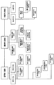
- FIG. 1 is a block diagram of an apparatus for improving fuel efficiency of a vehicle using inertial driving provided with a clutch sensitive to an operation section of an accelerator and a brake according to the present invention.
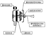
- FIG. 2 is a view for explaining a clutch coupled to the vehicle hub or knuckle according to the present invention.
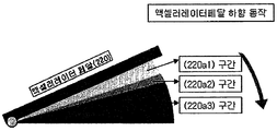
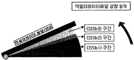
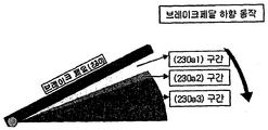
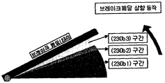
- 3 and 4 are diagrams for explaining the function according to the downward and upward operation of the accelerator pedal of the present invention, respectively.
- 5 and 6 are views for explaining the function according to the downward and upward operation of the brake pedal of the present invention, respectively.
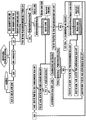
- FIG. 7 is a view for explaining the operation relationship of the clutch in response to the accelerator and the brake according to the present invention.
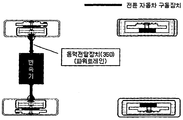
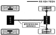
- FIG. 8 is a view showing a state in which an accelerator brake sensitive clutch coupled to an automobile hub or knuckle according to the present invention is mounted on a front wheel drive vehicle;
- FIG. 9 is a view showing an accelerator brake-sensitive clutch coupled to a vehicle hub or knuckle according to the present invention mounted on a rear wheel drive vehicle.
- FIG. 1 is a schematic diagram of an apparatus for improving fuel efficiency of a vehicle using inertia driving having a clutch sensitive to an operation section of an accelerator and a brake according to an exemplary embodiment of the present invention.
- a motor vehicle is connected to a power unit 100 including an engine 110a or a motor 110b for generating power that the vehicle can drive, the power unit 100, and a power transmission device 350.
- the control unit 200 is provided with a driving unit 300 for driving the vehicle by the power generated by the power unit, and an accelerator pedal 220 and a brake pedal 230 for accelerating or decelerating the vehicle by controlling the driving unit. ).
- the power unit 200 is a fuel control device 140 and the starting control device 140a for shutting off or supplying the fuel entering the engine 110a, the engine to shut off the fuel entering the engine Even when stopped, the electronic steering apparatus 130, the electrohydraulic pump 120a, and the electromagnetic vacuum pump 120b are provided so that the handle operation and the brake operation can be performed.
- an electric control device 150 is provided to block or supply electricity to the motor 110b.
- an electrohydraulic vacuum pump may be provided in place of the electrohydraulic pump and the electrovacuum pump.
- the driving unit 300 is connected to the power unit 100 and the power transmission unit 350 to drive the car, and connects between the power unit and the driving unit to connect or release the power of the power unit transferred to the driving unit.
- the clutch 330 is installed at a predetermined position of the power transmission device 350, and includes a clutch control device 330a for controlling the clutch, and a train sensor 340 for measuring the rotational speed of the power transmission device.
- the clutch is preferably installed in the hub 310 or the knuckle 320 of the vehicle close to the driving unit to minimize the resistance.
- the controller 200 may include an accelerator sensor 220a, an accelerator sensor 220a for detecting an up and down operation period of the accelerator pedal, a brake pedal 230, and a brake sensor 230a for detecting an up and down operation period of the brake pedal. And a control system 200a for controlling the clutch control device and the fuel control device, and a control switch 210 for determining whether the user uses the fuel efficiency improving device according to the present invention.
- the power unit 100 includes an engine 110a or a motor 110b for producing power required for driving a vehicle.
- it includes a fuel controller 140 and a starting controller 140a, and the fuel controller 140 functions to supply or shut off fuel to the engine 110a using fuel.
- the starting control device 140a functions to start the engine 110a using fuel.
- the electric control device 150 includes an electric control device 150, and the electric control device 150 functions to supply or cut off electricity of the motor 110b.
- the electronic steering device 130 and the electrohydraulic pump 120a and the electronic vacuum pump 120b which are required for braking the brake are mounted to facilitate the steering wheel operation even when the engine 110a or the motor 110b is stopped. Or, even when the motor is stopped, it provides a feature that poses no problem in steering and braking of the vehicle.
- the clutch 330 is mounted on the hub 310 or the knuckle 320 of the automobile, and the automobile wheel and the power transmission device 350 are provided.
- the clutch 330 is separated or coupled, and a clutch control device 330a for controlling the clutch and a train sensor 340 for detecting a rotation signal of the power transmission device are provided.
- the control unit 200 includes a control system 200a, a control switch 210, an accelerator pedal 220, an accelerator sensor 220a, a brake pedal 230.
- a brake sensor 230a is provided, and the controller 200 is connected to the power unit 100 and the driver 300 by an electrical signal.
- the control system 200a analyzes the rotation signal of the train sensor 340, and determines the signals of the accelerator sensor 220a and the brake sensor 230a to determine the fuel control device 140, the starting control device 140a, It functions to control the operation of the clutch control device 330a and the like.
- the control switch 210 of the control unit 200 functions to determine whether to use the fuel economy improvement apparatus according to the present invention.
- 3 and 4 are views for explaining the function according to the downward and upward operation of the accelerator pedal
- 5 and 6 are views for explaining the function according to the downward and upward operation of the brake pedal
- Figure 7 is an accelerator and the brake It is a figure for demonstrating the operation relationship of the clutch which responds to.
- the accelerator sensor 220a is connected to the accelerator pedal 220, and the accelerator sensor 220a may be configured to allow the driver to step on the accelerator pedal 220 so that the accelerator pedal 220 is in a section 220a1. When nothing happens.
- the fuel controller 140 supplies fuel to the engine 110a and the starting controller 140a starts the engine 110a.
- the electric controller 150 supplies electricity to the motor 110b to start the motor.
- the clutch wheel 330 is coupled to the separated vehicle wheel and the power transmission device 350 to prepare to transmit the engine 110a rotational power to the driving wheel.
- the accelerator sensor 220a accelerates by using the engine 110a or the motor 110b in a section 220b1 where the driver continues to press the accelerator pedal 220 of FIG. 4, or releases the accelerator pedal 220.
- the fuel control device 140 stops the fuel supply to the engine 110a to stop the engine 110a.
- the electric controller 150 cuts off electricity to the motor 110b to stop the motor.
- the clutch 330 separates the wheel and the power transmission unit 350 coupled to the power transmission unit 350 when the accelerator pedal 220 of FIG. 4 is moved from the section 220b2 to the section 220b3. It is possible to drive the inertia without resistance and no load.
- the brake pedal 230 is connected to the brake sensor 230a and the brake sensor 230a is a driver of FIG. 5.
- the brake pedal 230 is moved to the section 230a1 by stepping on the brake pedal 230, the deceleration starts, and when the brake pedal 230 is moved from the section 230a1 to the section 230a2, the fuel control device 140 is connected to the engine 110a.
- the fuel is supplied, and the starting controller 140a starts the engine 110a.
- the power unit 100 is a motor 110b
- the electric controller 150 supplies electricity to the motor 110b to start the motor.
- the clutch 330 is coupled to decelerate using the resistance of the power unit 100 and the power transmission unit 350.
- the fuel control unit 140 cuts off the fuel supply to the engine 110a so that the engine ( Stop 110a).
- the electric controller 150 cuts off electricity to the motor 110b to stop the motor.
- the vehicle wheel coupled by the clutch and the clutch 330 of the power transmission device 350 is separated while the resistance due to the power transmission device 350 is released.
- the hub 310 or the knuckle 320 of the drive unit 300 is coupled to the clutch 330 to which the clutch control device 330a is coupled, and the power transmission device 350 is coupled to the train sensor 340,
- the clutch 330 is coupled or separated by the clutch control device 330a to transfer the power of the power unit 100 to the wheels, or the clutch 330 is separated to minimize resistance by the power transmission device and to enable inertia driving. Function.
- the clutch 330 coupled to the hub 310 or the knuckle 320 reacts in response to the operation section of the accelerator pedal 220 and the brake pedal 230.
- the section and the section 230b2 of FIG. 6 function to be separated.
- the hub 310 or the knuckle 320 is coupled to the clutch 330 is installed to transmit or block the power of the power unit in the drive unit of the power transmission device for connecting the power unit and the drive unit. Can be installed in any position.
- FIG. 8 is a view showing a state in which an accelerator brake sensitive clutch coupled to an automobile hub or knuckle according to the present invention is mounted on a front wheel drive vehicle
- FIG. 9 is an accelerator brake sensitive type coupled to an automobile hub or knuckle according to the present invention.
- Figure shows the clutch mounted on the rear wheel drive car.
Landscapes
- Engineering & Computer Science (AREA)
- Chemical & Material Sciences (AREA)
- Combustion & Propulsion (AREA)
- Transportation (AREA)
- Mechanical Engineering (AREA)
- Hydraulic Clutches, Magnetic Clutches, Fluid Clutches, And Fluid Joints (AREA)
- Control Of Driving Devices And Active Controlling Of Vehicle (AREA)
- Electric Propulsion And Braking For Vehicles (AREA)
Applications Claiming Priority (6)
| Application Number | Priority Date | Filing Date | Title |
|---|---|---|---|
| KR10-2012-0047784 | 2012-05-06 | ||
| KR1020120047784A KR20120065979A (ko) | 2012-05-06 | 2012-05-06 | 유휴동력을 이용한 자동차 연비 개선방법 |
| KR10-2012-0111573 | 2012-10-08 | ||
| KR1020120111573A KR20120118843A (ko) | 2012-10-08 | 2012-10-08 | 액셀러레이터 브레이크 감응식 클러치 내장형 자동차허브 |
| KR1020130011618A KR20130018358A (ko) | 2013-02-01 | 2013-02-01 | 자동차 허브나 너클에 결합 된 액셀러레이터, 브레이크 감응 클러치 |
| KR10-2013-0011618 | 2013-02-01 |
Publications (1)
| Publication Number | Publication Date |
|---|---|
| WO2013168940A1 true WO2013168940A1 (fr) | 2013-11-14 |
Family
ID=49550922
Family Applications (1)
| Application Number | Title | Priority Date | Filing Date |
|---|---|---|---|
| PCT/KR2013/003908 Ceased WO2013168940A1 (fr) | 2012-05-06 | 2013-05-06 | Dispositif d'amélioration de rapport de carburant et procédé d'amélioration de rapport de carburant pour un véhicule ayant un embrayage pour détecter des sections de manœuvre de l'accélérateur et du frein, en utilisant la marche en roue libre |
Country Status (2)
| Country | Link |
|---|---|
| KR (1) | KR101482740B1 (fr) |
| WO (1) | WO2013168940A1 (fr) |
Cited By (2)
| Publication number | Priority date | Publication date | Assignee | Title |
|---|---|---|---|---|
| CN110121452A (zh) * | 2017-01-19 | 2019-08-13 | 舍弗勒技术股份两合公司 | 用于控制具有自动化离合器的车辆的滑行运行的方法 |
| KR102231972B1 (ko) * | 2019-10-08 | 2021-03-30 | 오토딘시스 주식회사 | 엑셀 및 브레이크 연동 동력 전달 기구 |
Families Citing this family (3)
| Publication number | Priority date | Publication date | Assignee | Title |
|---|---|---|---|---|
| KR101558376B1 (ko) | 2014-05-27 | 2015-10-07 | 현대자동차 주식회사 | 하이브리드 차량의 엔진 클러치 제어 장치 및 방법 |
| KR101725189B1 (ko) * | 2015-11-17 | 2017-04-12 | 주식회사 제이시스메디칼 | 초음파를 이용한 의료장치 및 트랜스듀서의 이동 제어 방법 |
| FR3052833B1 (fr) * | 2016-06-17 | 2019-07-19 | Renault S.A.S | Procede et dispositif de commande d’ouverture et de fermeture automatique d’embrayage |
Citations (5)
| Publication number | Priority date | Publication date | Assignee | Title |
|---|---|---|---|---|
| KR20050051098A (ko) * | 2003-11-27 | 2005-06-01 | 김인동 | 엔진 공회전 제어장치 및 이를 이용한 엔진 공회전 제어방법 |
| KR200431446Y1 (ko) * | 2006-08-31 | 2006-11-23 | 김영돈 | 자동차 주행상태에 따른 차량의 자동 중립 변속 착탈 장치 |
| JP2007050789A (ja) * | 2005-08-18 | 2007-03-01 | Toyota Motor Corp | ハイブリッド車の制御装置 |
| KR20080048013A (ko) * | 2008-05-07 | 2008-05-30 | 손영희 | 자동차 연료차단 장치 |
| JP2010137828A (ja) * | 2008-12-15 | 2010-06-24 | Toyota Motor Corp | 車両用ブレーキシステム |
-
2013
- 2013-05-06 WO PCT/KR2013/003908 patent/WO2013168940A1/fr not_active Ceased
- 2013-05-06 KR KR20130050865A patent/KR101482740B1/ko not_active Expired - Fee Related
Patent Citations (5)
| Publication number | Priority date | Publication date | Assignee | Title |
|---|---|---|---|---|
| KR20050051098A (ko) * | 2003-11-27 | 2005-06-01 | 김인동 | 엔진 공회전 제어장치 및 이를 이용한 엔진 공회전 제어방법 |
| JP2007050789A (ja) * | 2005-08-18 | 2007-03-01 | Toyota Motor Corp | ハイブリッド車の制御装置 |
| KR200431446Y1 (ko) * | 2006-08-31 | 2006-11-23 | 김영돈 | 자동차 주행상태에 따른 차량의 자동 중립 변속 착탈 장치 |
| KR20080048013A (ko) * | 2008-05-07 | 2008-05-30 | 손영희 | 자동차 연료차단 장치 |
| JP2010137828A (ja) * | 2008-12-15 | 2010-06-24 | Toyota Motor Corp | 車両用ブレーキシステム |
Cited By (4)
| Publication number | Priority date | Publication date | Assignee | Title |
|---|---|---|---|---|
| CN110121452A (zh) * | 2017-01-19 | 2019-08-13 | 舍弗勒技术股份两合公司 | 用于控制具有自动化离合器的车辆的滑行运行的方法 |
| KR102231972B1 (ko) * | 2019-10-08 | 2021-03-30 | 오토딘시스 주식회사 | 엑셀 및 브레이크 연동 동력 전달 기구 |
| WO2021071068A1 (fr) * | 2019-10-08 | 2021-04-15 | 오토딘시스 주식회사 | Accélérateur et mécanisme de transmission de puissance de timonerie de frein |
| US11542990B2 (en) | 2019-10-08 | 2023-01-03 | Autodyn Sys Inc. | Power transmission device interlocking with accelerator and brake pedal |
Also Published As
| Publication number | Publication date |
|---|---|
| KR20130124459A (ko) | 2013-11-14 |
| KR101482740B1 (ko) | 2015-01-14 |
Similar Documents
| Publication | Publication Date | Title |
|---|---|---|
| CN106347354B (zh) | 车辆的控制装置 | |
| CN102627068B (zh) | 轮毂电机式混合动力汽车的控制方法 | |
| CN104553886A (zh) | 一种电动汽车自动驻车控制方法及装置 | |
| CN103930937A (zh) | 驾驶支援装置 | |
| CN103687770A (zh) | 驾驶辅助系统 | |
| EP3174768B1 (fr) | Procédé de commande de frein de stationnement à commande électronique d'un véhicule ayant une transmission à double embrayage | |
| CN104742907A (zh) | 一种驻车控制方法和驻车控制系统 | |
| CN105966401A (zh) | 一种车辆滑行停机节油控制方法及系统 | |
| CN111836746A (zh) | 车辆控制装置、车辆控制方法和车辆追随行驶系统 | |
| KR101048142B1 (ko) | 하이브리드 차량의 회생제동토크 제어장치 및 방법 | |
| CN102923110B (zh) | 一种车辆用分段释放的电子驻车制动系统及控制方法 | |
| CN109572448A (zh) | 一种基于坡道传感器的纯电动汽车辅助控制方法及其控制系统 | |
| KR101482740B1 (ko) | 액셀러레이터와 브레이크의 동작구간에 감응하는 클러치를 구비한 관성주행을 이용한 자동차의 연비 개선 장치 | |
| WO2024003666A1 (fr) | Dispositif de régulation et procédé de régulation pour un système d'assistance au motocycliste | |
| CN114312349A (zh) | 一种纯电动汽车缓速行驶方法 | |
| CN102642531A (zh) | 四轮电动车的自动驻车装置 | |
| CN102358274A (zh) | 一种防止汽车制动跑偏的控制装置及其控制方法 | |
| CN101195372A (zh) | 汽车误踩油门控制装置 | |
| JP6253646B2 (ja) | 車両制御装置 | |
| CN201646704U (zh) | 电子驻车制动系统 | |
| CN208306624U (zh) | 一种基于电控液压制动的坡道起步辅助系统 | |
| JP7052331B2 (ja) | 車両制御装置 | |
| CN104742885A (zh) | 一种车辆驻车控制方法 | |
| JP5553743B2 (ja) | アイドルストップ車の制御装置 | |
| KR20130018358A (ko) | 자동차 허브나 너클에 결합 된 액셀러레이터, 브레이크 감응 클러치 |
Legal Events
| Date | Code | Title | Description |
|---|---|---|---|
| 121 | Ep: the epo has been informed by wipo that ep was designated in this application |
Ref document number: 13788625 Country of ref document: EP Kind code of ref document: A1 |
|
| NENP | Non-entry into the national phase |
Ref country code: DE |
|
| 122 | Ep: pct application non-entry in european phase |
Ref document number: 13788625 Country of ref document: EP Kind code of ref document: A1 |