WO2013171838A1 - Jeu à commande sans fil - Google Patents
Jeu à commande sans fil Download PDFInfo
- Publication number
- WO2013171838A1 WO2013171838A1 PCT/JP2012/062370 JP2012062370W WO2013171838A1 WO 2013171838 A1 WO2013171838 A1 WO 2013171838A1 JP 2012062370 W JP2012062370 W JP 2012062370W WO 2013171838 A1 WO2013171838 A1 WO 2013171838A1
- Authority
- WO
- WIPO (PCT)
- Prior art keywords
- toy
- control signal
- controller
- unit
- control unit
- Prior art date
- Legal status (The legal status is an assumption and is not a legal conclusion. Google has not performed a legal analysis and makes no representation as to the accuracy of the status listed.)
- Ceased
Links
Images




Classifications
-
- A—HUMAN NECESSITIES
- A63—SPORTS; GAMES; AMUSEMENTS
- A63H—TOYS, e.g. TOPS, DOLLS, HOOPS OR BUILDING BLOCKS
- A63H30/00—Remote-control arrangements specially adapted for toys, e.g. for toy vehicles
- A63H30/02—Electrical arrangements
- A63H30/04—Electrical arrangements using wireless transmission
Definitions
- the present invention relates to a wirelessly controlled toy.
- a wirelessly controlled toy that can operate a toy body based on a control signal transmitted from a controller by wireless communication using infrared (IR) or the like is known (for example, see Patent Document 1).
- the toy body to be operated is a model of the shape of a vehicle such as a car, a ship, or an airplane, or a model of the shape of various robots, etc. It has been realized in various shapes.
- the operation mode such as forward / backward / turning / stopping is transmitted as a control signal from the controller
- the toy body travels and rotates according to its own shape according to the operation mode based on the control signal, An operation such as walking is executed.
- Such a rechargeable toy includes a toy body including a rechargeable battery (charger) and a drive source such as a motor, and a generator that is a power generation means separate from the toy body.
- a rechargeable toy to a wireless control toy has also been proposed.
- a generator is required, but an integrated controller and generator is also proposed (for example, see Patent Document 3).
- the toy body and the generator are connected via a lead wire or the like, and the electric power obtained by the self-power generation in the generator is stored in the rechargeable battery of the toy body. In this way, it operates using the power supplied from the rechargeable battery. For this reason, a disposable battery such as a dry battery is not required, and an economical and ecological toy is realized.
- the controller and the generator are integrated, and the controller itself is heavier than the conventional controller, or the controller is provided with a power generation handle. There is a possibility that the operation may be hindered, and as a result, there is a concern that the operability of the toy body in the controller is lowered.
- the controller is also equipped with a battery such as a dry battery or a battery such as a rechargeable battery that is charged by an integrated generator. There is also a need.
- the object of the present invention is to make the generator handle and the controller handle for operating the toy main unit in common to suppress the increase in the number of parts and to secure the power necessary for the controller itself by the generator.
- An object of the present invention is to provide a wirelessly controlled toy capable of (power generation) and detecting the number of rotations of an operation handle (power generation handle) without performing a special sensor to perform wireless control of the toy body.
- the invention according to claim 1
- An operation handle connected to the rotating shaft of the DC motor;
- a controller having a first control unit that generates a control signal that instructs an operation mode based on the number of rotations obtained from the electrical noise of the output of the DC motor and transmits the control signal wirelessly;
- a toy body having a second control unit for controlling its own operation in an operation mode instructed by the received control signal.
- the invention according to claim 2
- An operation handle connected to a rotating shaft of a DC motor as a generator;
- a power generation charging unit that removes electrical noise from the output of the DC motor and switches the polarity to apply to the battery,
- a controller having a first control unit that generates and transmits wirelessly a control signal that indicates an operation mode based on the number of rotations obtained from the electrical noise;
- a toy body having a second control unit for controlling its own operation based on the received control signal;
- the operation handle is rotated to generate electric power necessary for the controller's own operation to transmit the control signal to the first controller, and the second controller controls the operation mode of the toy body. Control is performed in an operation mode instructed by a signal.
- the invention described in claim 3 An operation handle connected to a rotating shaft of a DC motor as a generator; A power generation charging unit that removes electrical noise from the output of the DC motor and switches the polarity to be applied to the capacitor and supplies the output of the capacitor to the outside through the first connection unit; A controller having a first control unit that generates and transmits wirelessly a control signal that indicates an operation mode based on the number of rotations obtained from the electrical noise; A rechargeable battery; A second connecting portion connected to both ends of the rechargeable battery; A toy body having a second control unit that controls its own operation based on the received control signal; At the time of charging, the operation handle is rotated to generate power, and the output of the battery is applied to the rechargeable battery via the first and second connecting portions to charge, and at the time of wireless control, the operation handle is rotated. The controller generates power necessary for its own operation and transmits the control signal to the first control unit, and the second control unit is instructed to operate the toy body by the control signal. It controls to a mode.
- the invention according to claim 4 The wirelessly controlled toy according to any one of claims 1 to 3,
- the first controller is The rotation speed is detected by counting pulses extracted from the electrical noise.
- the invention according to claim 5 The wirelessly controlled toy according to any one of claims 1 to 4,
- the first controller is When the number of rotations exceeds a predetermined number of rotations, a control signal for instructing a moving speed of the toy body that is one step earlier is generated and transmitted wirelessly.
- the invention described in claim 6 The wirelessly controlled toy according to any one of claims 1 to 4,
- the first controller is A control signal instructing a moving speed of the toy main body proportional to the rotation speed is generated and transmitted wirelessly.
- the invention described in claim 7 The wirelessly controlled toy according to any one of claims 1 to 4,
- the first controller is A control signal that specifies the operation of the toy body according to the number of revolutions is generated and transmitted wirelessly
- the second controller is Control is performed such that the toy body performs an operation designated by the control signal.
- the operation handle connected to the rotating shaft of the DC motor and the control signal indicating the operation mode based on the rotational speed obtained from the electric noise of the output of the DC motor are generated and transmitted wirelessly.
- a controller having one control unit and a toy body having a second control unit that controls its own operation in the operation mode instructed by the received control signal, a special sensor is not provided. It is possible to provide a wirelessly controlled toy that can detect the number of rotations of the operation handle and wirelessly control the toy body.
- the wirelessly controlled toy includes a controller 100 and, for example, a toy main body 200 as a traveling toy imitating the shape of an automobile.
- the controller 100 is provided with (connected to) an operation handle 2 (also serving as a power generation handle) that is an operation unit so as to be rotatable in the RR direction (right rotation) and the RL direction (left rotation) with respect to the controller main body 1.
- a part of the controller 100 is provided with a connection part CN1 for connection with the toy main body 200 during charging.
- a connection portion CN2 for connecting to the controller 100 having a power generation function at the time of charging is provided in a part of the toy main body 200.
- connection cable CB When charging the toy main body 200, one end of the connection cable CB is connected to the connection portion CN1 of the controller 100, and the other end of the connection cable CB is connected to the connection portion CN2 of the toy main body 200. Thereafter, the user rotates the operation handle 2 (corresponding to the power generation handle) of the controller 100 to generate power by turning a direct current motor, which is a generator, directly or via a rotation acceleration gear, and the generated voltage is connected.
- the battery is supplied to the toy main body 200 via the cable CB, and the rechargeable battery provided in the toy main body 200 is charged.
- connection cable CB is disconnected from the connection portion CN1 of the controller 100 and the connection portion CN2 of the toy main body 200, and the controller 100 The toy body 200 is separated.
- the user generates electric power necessary for the operation of the controller 100 itself by rotating the operation handle 2 (corresponding to the power generation handle) of the controller 100.
- the controller 100 generates a control signal for controlling the toy body 200 and transmits it wirelessly, and controls the toy body 200 wirelessly.
- the toy body 200 is moved forward at a preset initial speed, and the moving speed (operation mode) of the toy body 200 is controlled according to the number of rotations of the operation handle 2. For example, when the rotational speed exceeds a predetermined rotational speed, the moving speed (operation mode) of the toy main body 200 is increased (shifted).
- controller 100 during charging of the toy main body 200 and during wireless control of the toy main body 200 will be described in more detail with reference to FIGS.
- the filter circuit 4, the polarity switching circuit 5, the capacitor 6, and the connection unit 7 are the power generation charging unit 101, the pulse extraction circuit 8, the count unit 9, the phase detection unit 10, the control signal generation unit 11, and the transmission unit. 12 respectively constitute the control unit 102.
- the functions of the count unit 9, the phase detection unit 10, and the control signal generation unit 11 are realized by a known electronic circuit, or a single chip microprocessor or the like (hereinafter simply referred to as a microprocessor).
- the microprocessor controls the controller 100.
- the microprocessor has various inputs and outputs (all not shown) such as a central processing unit (CPU), a random access memory (RAM), a read only memory (ROM), and an input / output (I / O) port. And various control operations are performed in accordance with various processing programs (not shown) for the controller 100 stored in the ROM.
- the CPU stores various processing results in a storage area in the RAM.
- the RAM includes, for example, a program storage area for expanding a processing program executed by the CPU, a data storage area for storing input data, a processing result generated when the processing program is executed, and the like.
- the ROM executes a program stored in the form of computer-readable program code, specifically, a system program that can be executed by the controller 100, various processing programs that can be executed by the system program, and these various processing programs.
- the data used at the time is stored.
- the I / O port takes in data from outside the microprocessor, outputs data, controls circuits outside the microprocessor, and the like.
- the operation handle 2 is attached (coupled) to the rotating shaft of the DC motor 3 that is a generator directly or via a rotation acceleration gear so as to be rotatable in the clockwise and counterclockwise directions.
- a filter circuit 4 for removing noise such as an LPF (Low-pass filter) circuit is connected to an input terminal of a polarity switching circuit 5, and an output of the polarity switching circuit 5 such as a diode bridge is a capacitor 6 which is a capacitor.
- connecting portions 7 corresponding to CN1 used for connecting to the toy main body 200 during charging.
- the output voltage at both ends of the capacitor 6 that is a capacitor is supplied to the control unit 102 and other circuits constituting the controller 100 as a power supply for the entire controller 100.
- the output of the pulse extraction circuit 8 that cuts the DC component and shapes the pulse waveform includes an input terminal of a count unit 9 that counts the number of extracted pulses and a phase detection unit 10 that detects the phase of the extracted pulses. Connected to each.
- the outputs of the count unit 9 and the phase detection unit 10 are connected to input terminals of a control signal generation unit 11 that generates a control signal for controlling the toy main body 200, respectively.
- the output of the control signal generator 11 is connected to the input terminal of the transmitter 12 that transmits the control signal using infrared rays (wireless).
- the rotation shaft of the DC motor 3 that is a generator attached (connected) directly or via a rotation acceleration gear is also synchronized. Rotate.
- the DC motor 3 is provided with a plurality of commutators CM on the rotating shaft MT, and these commutators CM sequentially contact the brush BR and cut to switch the flow of electricity.
- the DC voltage is generated.
- the commutator CM and the brush BR repeat contact / cutting, a spark is generated, and electrical noise is generated due to the spark.
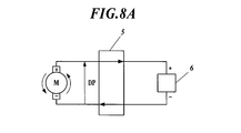
- the generated DC voltage DP (positive polarity) as shown in FIG. A voltage on which the electric noise NP is superimposed is generated between the output terminals of the DC motor 3.
- the controller 100 may malfunction and cause problems, so the filter circuit 4 (LPF circuit) of the power generation charging unit 101 may be used. Used to remove such electrical noise components.
- the polarity of the voltage generated by the polarity switching circuit 5 such as a diode bridge is made uniform.
- a DC voltage DP positive polarity
- the polarity switching circuit 5 directly outputs the output of the DC motor 3 as a capacitor. 6 is applied to both ends and charged.
- a DC voltage DM negative polarity
- the polarity switching circuit 5 switches the polarity of the output of the DC motor 3 to The battery 6 is charged by being applied to both ends. That is, even when the DC motor 3 is rotated in the forward direction or in the reverse direction, a DC voltage having the same polarity is always applied to both ends of the capacitor 6 as a capacitor by the polarity switching circuit 5. The state will be maintained.
- the voltage charged in the capacitor 6 as a capacitor charges the toy main body 200 via the connection unit 7 or is supplied to the control unit 102 and other circuits as a power supply for the entire controller 100 and consumed. It will be.
- control unit 102 during wireless control of the toy main body 200 will be described with reference to the flowchart of FIG.
- the pulse extraction circuit 8 extracts electrical noise superimposed on the voltage at the output terminal of the DC motor 3. Specifically, the direct current component is cut from the voltage at the output terminal of the direct current motor 3 to extract electric noise, and the waveform is shaped so that it can be used in the logic circuit (microprocessor) in the subsequent stage.
- the count unit 9 (microprocessor) of the control unit 102 counts a predetermined number of times of the pulse extracted and shaped by the pulse extraction unit 8, and outputs the count result to the control signal generation unit. 11 (step S1). That is, the above-described electric noise is generated due to contact / cutting with the plurality of commutators CM provided on the rotation shaft MT of the DC motor 3 and the brush BR, and thus is proportional to the rotation speed of the rotation shaft MT. For this reason, the counting unit 9 (microprocessor) of the control unit 102 counts the pulses from which such electrical noise has been extracted, so that the rotational speed of the DC motor 3, in other words, the operation handle without a special sensor is provided. 2 can be detected.
- the control signal generation unit 11 (microprocessor) of the control unit 102 determines whether or not the count number output from the count unit 9 exceeds a preset threshold value (step S2). In other words, the case where the rotational speed of the operation handle 2 exceeds a predetermined rotational speed is detected.
- the control signal generation unit 11 (microprocessor) of the control unit 102 determines that a preset threshold value has been exceeded (step S1: Yes)
- the control signal generation unit 11 (microprocessor) of the control unit 102 ) Generates a control signal (control signal for instructing the moving speed (operation mode)) that increases the movement speed (operation mode) by one step (step S3).
- control signal generation unit 11 determines that the preset threshold value is not exceeded (step S1: No)
- the control signal generation unit 11 determines that the preset threshold value is not exceeded (step S1: No)
- the processor generates a control signal (control signal for instructing the moving speed (operation mode)) that keeps the initial speed set in advance (operation mode) (step S4).
- the control signal generation unit 11 transmits the generated control signal (control signal instructing the moving speed (operation mode)) to the toy main body 200 via the transmission unit 12.
- the transmission unit 12 is driven by output from the I / O port of the microprocessor to transmit a control signal generated using infrared (wireless).
- the reception unit 16 and the drive signal generation unit 17 constitute a control unit 201.
- the function of the drive signal generation unit 17 is realized by a known electronic circuit or a microprocessor.
- the microprocessor controls the toy main body 200.
- the microprocessor includes various input / outputs (all not shown) such as a CPU, RAM, ROM, and I / O port, and according to various processing programs (not shown) for the toy main body 200 stored in the ROM. Perform various control operations.
- the CPU stores various processing results in a storage area in the RAM.
- the RAM includes, for example, a program storage area for expanding a processing program executed by the CPU, a data storage area for storing input data, a processing result generated when the processing program is executed, and the like.
- the ROM stores a program stored in the form of computer-readable program code, specifically, a system program that can be executed by the toy main body 200, various processing programs that can be executed by the system program, and the various processing programs that are executed.
- the data used for the storage is stored.
- the I / O port takes in data from outside the microprocessor, outputs data, controls circuits outside the microprocessor, and the like.
- the output of the connection unit 13 (corresponding to CN 2) used during charging is connected to the rechargeable battery 14 that is a battery, and the output of the rechargeable battery 14 is connected to the power supply terminal of the drive unit 15. Further, although not shown in FIG. 10, the supply power that is the output of the rechargeable battery 14 is supplied to the control unit 201 that controls the toy main body 200.
- the output of the receiving unit 16 that receives the control signal using infrared (wireless) is connected to the drive signal generating unit 17, and the output of the drive signal generating unit 17 is connected to the control terminal of the drive unit 15.
- the voltage that is the output of the battery 6 that is a capacitor of the controller 100 is applied to the rechargeable battery 14 that is a battery via the connection part 7 (first connection part) and the connection part 13 (second connection part) of the controller 100.
- the rechargeable battery 14 is charged.
- control unit 201 during wireless control of the toy main body 200 will be described with reference to the flowchart of FIG.
- the receiving unit 16 receives the infrared rays (wireless) transmitted from the transmitting unit 12 of the controller 100, extracts a control signal, and shapes the waveform so that it can be used by a logic circuit (microprocessor) at the subsequent stage.
- a logic circuit microprocessor
- the drive signal generation unit 17 (microprocessor) of the control unit 201 determines whether or not the control signal received and shaped by the reception unit 16 has been acquired (step S11).
- the drive signal generation unit 17 (microprocessor) of the control unit 201 determines that the control signal is not acquired (step S11: No)
- the process returns to step S11.
- the drive signal generation unit 17 (microprocessor) of the control unit 201 determines that the control signal has been acquired (step S11: Yes)
- the drive signal generation unit 17 (microprocessor) of the control unit 201 captures the control signal. It is determined whether or not the control signal maintains a preset initial speed based on the speed indicated by the control signal (step S12).
- step S12 when the drive signal generation unit 17 (microprocessor) of the control unit 201 determines that the control signal is to maintain the preset initial speed (step S12: Yes), the drive signal generation unit of the control unit 201 17 (microprocessor) controls the drive unit 15 to control the moving speed (operation mode) to the speed (operation mode) indicated by the control signal. In other words, the preset initial speed of the toy body 200 is maintained (step S13), and the process returns to step S11.
- step S12 determines that it is not a control signal for maintaining the initial speed
- step S12 determines that it is not a control signal for maintaining the initial speed
- step S14 the drive signal generation unit 17 (microprocessor) of the control unit 201
- the drive unit 15 is controlled to control the moving speed (operation mode) to the speed (operation mode) indicated by the control signal.
- the moving speed (operation mode) of the toy body 200 is increased by one step (shifted) (step S14), and the process returns to step S11.
- the DC motor 3 is used as a generator, and the operation handle 2 connected to the rotating shaft of the DC motor 3 is rotated to generate electric power to charge the rechargeable battery 14 of the toy main body 200.
- the operation handle 2 of the controller 100 is rotated to charge the toy main body 200 during charging, and the controller itself is rotated by rotating the operation handle 2 of the controller 100 during wireless control. It is possible to secure the power necessary for the operation (power generation) and to control the moving speed (operation mode) of the toy main body 200 according to the number of rotations of the operation handle 2.
- the user rotates the operation handle 2 (corresponding to the power generation handle) of the controller 100 to generate electric power necessary for the operation of the controller 100 itself. Generate electricity.
- the controller 100 generates a control signal that indicates the traveling direction (operation mode) according to the rotation direction of the operation handle 2 that is rotated by the user, and transmits the control signal wirelessly. Controls whether the vehicle moves forward or backwards. In other words, the traveling direction (motion mode) of the toy body 200 is controlled in the direction (motion mode) indicated by the control signal.
- control unit 102 during wireless control of the toy body 200 will be described with reference to the flowchart of FIG.
- the pulse extraction circuit 8 extracts electrical noise superimposed on the voltage at the output terminal of the DC motor 3. Specifically, the direct current component is cut from the voltage at the output terminal of the direct current motor 3 to extract electric noise, and the waveform is shaped so that it can be used by a subsequent microprocessor.
- the phase detection unit 10 (microprocessor) of the control unit 102 detects the phase of the pulse extracted and shaped by the pulse extraction unit 8 and outputs the detection result to the control signal generation unit 11.
- the rotating shaft MT (the operation handle 2).
- the phase is different between when rotating in the forward direction and when rotating in the reverse direction. That is, for example, when the waveform of the electrical noise when the operation handle 2 is rotated in the forward direction is shown in FIG.
- the waveform of the electrical noise generated by rotating the operation handle 2 in the reverse direction is as shown in FIG. 13B.
- the phases will be 180 degrees different from each other. In other words, by detecting the difference in the phase of the electrical noise, it is possible to detect the rotation direction of the operation handle 2 without providing a special sensor.
- the control signal generation unit 11 (microprocessor) of the control unit 102 determines whether or not the operation handle 2 (rotation axis MT) is rotating in the forward direction based on the detection result output from the phase detection unit 10 (step S22). ).
- the control signal generation unit 11 (microprocessor) of the control unit 102 determines that the operation handle 2 (rotation axis MT) is rotating in the forward direction (step S22: Yes)
- generation part 11 (microprocessor) produces
- control signal generation unit 11 determines that the operation handle 2 (rotating shaft MT) is not rotating in the forward direction (that is, rotating in the reverse direction) (step S22: No)
- the control signal generation unit 11 generates a control signal for retreating the toy main body 200 (a control signal indicating a traveling direction (operation mode))
- step S24 the control signal generation unit 11 (microprocessor) of the control unit 102 transmits the generated control signal (control signal indicating the traveling direction (operation mode)) to the toy main body 200 via the transmission unit 12.
- the transmission unit 12 is driven by output from the I / O port of the microprocessor to transmit a control signal generated using infrared (wireless).
- control unit 201 during wireless control of the toy main body 200 will be described with reference to the flowchart of FIG.
- the receiving unit 16 receives the infrared rays (wireless) transmitted from the transmitting unit 12 of the controller 100, extracts a control signal, and shapes the waveform so that it can be used by a logic circuit (microprocessor) at the subsequent stage.
- a logic circuit microprocessor
- the drive signal generation unit 17 (microprocessor) of the control unit 201 determines whether or not the control signal received and shaped by the reception unit 16 has been acquired (step S31).
- the drive signal generation unit 17 (microprocessor) of the control unit 201 determines that the control signal has not been acquired (step S31: No)
- the process returns to step S31.
- the drive signal generation unit 17 (microprocessor) of the control unit 201 determines that the control signal has been acquired (step S31: Yes)
- the drive signal generation unit 17 (microprocessor) of the control unit 201 captures. It is determined whether or not to advance based on the traveling direction (operation mode) indicated by the control signal (step S32).
- step S32 when the drive signal generation unit 17 (microprocessor) of the control unit 201 determines that the control signal is a forward control signal (step S32: Yes), the drive signal generation unit 17 (microprocessor) of the control unit 201 The drive unit 15 is controlled to control the traveling direction (operation mode) in the direction (operation mode) indicated by the control signal. In other words, the toy main body 200 is advanced (step S33), and the process returns to step S31.
- step S32 determines that the control signal is not a forward control signal (that is, reverses) (step S32: No)
- step S32 determines that the control signal is not a forward control signal (that is, reverses)
- step S32 determines that the control signal is not a forward control signal (that is, reverses)
- step S32 determines that the control signal is not a forward control signal (that is, reverses)
- step S32 determines that the control signal is not a forward control signal (that is, reverses)
- step S32 determines that the control signal is not a forward control signal (that is, reverses)
- step S24 determines that the control signal is not a forward control signal (that is, reverses)
- the DC motor 3 is used as a generator, and the operation handle 2 connected to the rotating shaft of the DC motor 3 is rotated to generate power and charge the rechargeable battery 14 of the toy main body 200.
- the operation handle 2 of the controller 100 is rotated to charge the toy body 200 during charging, and the controller itself is rotated by rotating the operation handle 2 of the controller 100 during wireless control. It is possible to secure the power necessary for the operation (power generation) and to control the traveling direction of the toy body 200 (operation mode: forward and backward) according to the rotation direction of the operation handle 2.
- Modification 1 of the first embodiment and the second embodiment of the present invention will be described.
- the toy main body 200 such as FIG. 2, the toy main body 200 is described as a rechargeable battery equipped with a rechargeable battery 14, but is driven by a non-rechargeable battery such as a normal dry battery. It doesn't matter. That is, the first modification is realized by replacing the rechargeable battery 14 in FIG. 10 with a non-rechargeable battery such as a normal dry battery.
- the connecting portion 7 (CN1) of the controller 100 and the connecting portion 13 (CN2) of the toy body are not necessary.
- the operations of the controller 100 and the toy main body 200 are the same as those in the first and second embodiments of the invention.
- the toy main body 200 is made non-rechargeable, so that charging work is not necessary, and at the time of wireless control, the operation handle 2 of the controller 100 is rotated to be necessary for the operation of the controller itself. While securing (power generation) electric power, the moving speed (operation mode) of the toy body 200 according to the number of rotations of the operation handle 2 or the traveling direction (operation mode) of the toy body 200 according to the rotation direction of the operation handle 2. : Forward and backward) can be controlled respectively.
- Modification 2 Modification 2 of the first embodiment of the present invention will be described.
- the operation handle 2 of the controller 100 is rotated to secure (electric power generation) electric power necessary for the operation of the controller itself, and the toy body according to the number of rotations of the operation handle 2
- the movement speed (operation mode) of 200 is controlled in two stages
- the movement speed (operation mode) of the toy main body 200 is controlled in proportion to the number of rotations of the operation handle 2. That is, in the description of the operation of the controller 100 in FIG. 9, the control signal generation unit 11 (microprocessor) of the control unit 102 specifies the moving speed (operation mode) proportional to the count number output from the counting unit 9.
- a signal is generated and transmitted to the toy body 200 by infrared (wireless).
- the drive signal generation unit 17 microprocessor
- the control unit 201 controls the drive unit 15 to receive the movement speed (operation mode) of the toy body 200. Controls the speed specified by the control signal.
- the toy body 200 may be either rechargeable or non-rechargeable.
- the operation handle 2 of the controller 100 is rotated to secure the power necessary for the operation of the controller itself (power generation), and in proportion to the rotation speed of the operation handle 2.
- the moving speed (operation mode) of the toy main body 200 can be controlled.
- a designated operation other than the moving speed (operation mode) and the traveling direction (operation mode: forward / backward movement) of the toy main body 200 is caused in accordance with the rotation speed or the rotation direction of the operation handle 2.
- the toy main body 200 is turned to the right or turned to the left according to the number of rotations of the operation handle 2.
- the toy main body 200 is turned to the right or turned to the left according to the rotation direction of the operation handle 2. That is, in the description of the operation of the controller 100 in FIGS. 9 and 12, the control signal generation unit 11 (microprocessor) of the control unit 102 detects the count number output from the count unit 9 and the detection output from the phase detection unit 10.
- a control signal (control signal for designating an operation) for causing the toy body 200 to turn right or turn left is generated and transmitted to the toy body 200 by infrared (wireless).
- the drive signal generation unit 17 (microprocessor) of the control unit 201 controls the drive unit 15 and receives the control signal (control for specifying the operation).
- the toy main body 200 is controlled so as to perform the operation specified by the signal) (to make the toy main body 200 turn right or turn left).
- the operation specified by the control signal is not limited to the right turn or the left turn, and other operations are controlled according to the number of rotations and the direction of rotation of the operation handle 2. It doesn't matter.
- the toy body 200 may be either rechargeable or non-rechargeable.
- the operation handle 2 of the controller 100 is rotated to secure the power necessary for the operation of the controller itself (power generation), and the operation handle 2 can be rotated in the rotation speed and the rotation direction. Accordingly, by performing an operation designated by a control signal such as turning the toy body 200 to the right or turning it to the left, it is possible to perform more complicated wireless control of the toy body.
- the toy body 200 is exemplified as a traveling toy simulating the shape of an automobile.
- the toy body 200 is, for example, a dog or a cat.
- the toy body 200 may be raised according to the number of rotations or the direction of rotation of the operation handle 2, or the corresponding animal may be screamed.
- the operations different from those of the first to third modifications are generated. That is, in the description of the operation of the controller 100 in FIGS.
- the control signal generation unit 11 (microprocessor) of the control unit 102 detects the count number output from the count unit 9 and the detection output from the phase detection unit 10. Based on the result, the toy body 200 is raised, or a control signal (control signal for designating an action) for generating a sound of the corresponding animal is generated and transmitted to the toy body 200 by infrared (wireless).
- the drive signal generation unit 17 (microprocessor) of the control unit 201 controls the drive unit 15 and receives the control signal (control for specifying the operation).
- the toy body 200 is controlled so as to perform the operation specified in the signal) (such as raising the toy body 200 or making the corresponding animal cry).
- the toy main body 200 is separately provided with an electroacoustic conversion unit such as a speaker, and the drive signal generation unit 17 generates an electric signal of the corresponding animal's cry and outputs it to the electroacoustic conversion unit. And it outputs as an acoustic signal (voice
- voice acoustic signal
- voice acoustic signal
- voice voice
- the change in the operation is not limited to raising or making a sound of the corresponding animal, but other operations occur depending on the number of rotations and the direction of rotation of the operation handle 2. You may control so.
- the toy main body 200 may be either rechargeable or non-rechargeable.
- the operation handle 2 of the controller 100 is rotated to ensure power generation (power generation) necessary for the operation of the controller itself, and at the same time, the rotation speed and the rotation direction of the operation handle 2 are increased.
- a control signal such as starting up a toy body 200 that is a running toy imitating the shape of an animal such as a dog, cat, cow, or horse, or making a sound of the corresponding animal.
- connection portion CN1 first connection portion of the controller 100 and the connection portion of the toy main body 200 using the cable CB.
- description is made of charging by connecting CN2 (second connection portion) of course, without using the cable CB, the connection portion 7 (first connection portion) and the connection portion 13 ( A voltage that is the output of the battery 6 that is a capacitor of the controller 100 is applied to the rechargeable battery 14 that is a battery via the second connection portion), and the rechargeable battery 14 may be charged.
- the movement speed (operation mode) of the toy main body to be controlled is assigned based on the number of rotations of the operation handle 2, and this is controlled.
- the operation handle is controlled.
- the traveling direction (operation mode) of the toy body that is the control object is assigned and controlled based on the rotational direction of 2, and of course, the traveling direction of the toy body that is the control object based on the number of rotations of the operation handle 2.
- (Operation mode) may be assigned and controlled, and the movement speed (operation mode) of the toy main body to be controlled may be assigned and controlled based on the rotation direction of the operation handle 2.
- control object may be assigned to the rotation speed of the operation handle 2, or another control object may be assigned to the rotation direction of the operation handle 2.
- the rotation speed is N (N is an arbitrary integer) or more
- the rotation direction is forward rotation (AND condition) or the rotation speed. May be assigned to N or less (N is an arbitrary integer) or the rotation direction is the reverse rotation (OR condition).
- a normal dry cell or the like is used as a power source for supplying power required by the control unit 102, or an external power source such as an AC adapter.
- the power generation charging unit 101 in the controller 100 is not necessary.
- the toy body 200 which is a running toy imitating the shape of an animal such as a dog, a cat, a cow, or a horse is raised, or that the corresponding animal is screamed.
- operations such as single-wheel traveling, wheelie traveling, etc., for example, a horn is sounded, a police car or a fire truck siren, etc. It does not matter if it sounds.
- Appendix 1 An operation handle connected to the rotating shaft of the DC motor; A controller having a first control unit that generates a control signal that instructs an operation mode based on a rotation direction obtained from an electrical noise of an output of the DC motor, and transmits the control signal wirelessly; A radio-controlled toy comprising: a toy body having a second control unit that controls its own operation in an operation mode instructed by the received control signal.
- Appendix 2 An operation handle connected to a rotating shaft of a DC motor as a generator; A power generation charging unit that removes electrical noise from the output of the DC motor and switches the polarity to apply to the battery, A controller having a first control unit that generates and transmits wirelessly a control signal that indicates an operation mode based on the rotation direction obtained from the electrical noise; A toy body having a second control unit for controlling its own operation based on the received control signal; The handle is rotated to generate electric power necessary for the controller itself to transmit the control signal to the first control unit, and the second control unit changes the operation mode of the toy main body to the control signal.
- a wirelessly controlled toy characterized in that the operation is controlled in accordance with the operation mode indicated in 1.
- Appendix 3 An operation handle connected to a rotating shaft of a DC motor as a generator; A power generation charging unit that removes electrical noise from the output of the DC motor and switches the polarity to be applied to the capacitor and supplies the output of the capacitor to the outside through the first connection unit; A controller having a first control unit that generates and transmits wirelessly a control signal that indicates an operation mode based on the rotation direction obtained from the electrical noise; A rechargeable battery; A second connecting portion connected to both ends of the rechargeable battery; A toy body having a second control unit that controls its own operation based on the received control signal; At the time of charging, the operation handle is rotated to generate power, and the output of the battery is applied to the rechargeable battery via the first and second connecting portions to charge, and at the time of wireless control, the operation handle is rotated. The controller generates power necessary for its own operation and transmits the control signal to the first control unit, and the second control unit is instructed to operate the toy body by the control signal.
- a wirelessly controlled toy characterized by being controlled
- the first controller is The wirelessly controlled toy according to any one of appendices 1 to 3, wherein a phase of a pulse extracted from the electrical noise is detected, and the rotation direction is detected based on the detected phase.
- the first controller is The wirelessly controlled toy according to any one of appendices 1 to 4, wherein the control signal that indicates the traveling direction based on the rotation direction is generated and transmitted wirelessly.
- the first controller is A control signal that specifies the operation of the toy body according to the rotation direction is generated and transmitted wirelessly
- the second controller is The wirelessly controlled toy according to any one of appendices 1 to 4, wherein the toy body is controlled to perform an operation specified by the control signal.
- the present invention can be used particularly in the field of wirelessly controlled toys capable of charging the power source in the toy body.
- Controller 101 Electric power generation charge part 102 Control part 200 Toy main body 201 Control part 1 Controller main body 2 Operation handle 3 DC motor 4 Filter circuit 5 Polarity switching circuit 6 Capacitor 7,13 Connection part 8 Pulse extraction circuit 9 Count part 10 Phase detection part 11 Control signal generator 12 Transmitter 14 Rechargeable battery 15 Drive unit 16 Receiver 17 Drive signal generator
Landscapes
- Engineering & Computer Science (AREA)
- Computer Networks & Wireless Communication (AREA)
- Toys (AREA)
Abstract
La présente invention concerne un jeu à commande sans fil avec lequel il est possible, sans qu'il ne comprenne de capteur spécial, de détecter la vitesse de rotation ou le sens de rotation d'une manette fonctionnelle, et de réaliser la commande sans fil d'un corps principal de jeu. Un jeu à commande sans fil comprend : une manette fonctionnelle, qui est couplée à un axe de rotation d'un moteur à courant continu ; un dispositif de commande, comprenant en outre une première unité de commande qui, en se basant sur la vitesse de rotation obtenue à partir du bruit électrique de la sortie du moteur à courant continu, génère un signal de commande qui instruit un état fonctionnel et qui effectue une transmission sans fil de ce dernier ; et un corps principal de jeu, comprenant en outre une seconde unité de commande qui commande son propre fonctionnement dans l'état fonctionnel qui est instruit avec un signal de commande reçu.
Priority Applications (2)
| Application Number | Priority Date | Filing Date | Title |
|---|---|---|---|
| JP2014515382A JP5735709B2 (ja) | 2012-05-15 | 2012-05-15 | 無線コントロール式玩具 |
| PCT/JP2012/062370 WO2013171838A1 (fr) | 2012-05-15 | 2012-05-15 | Jeu à commande sans fil |
Applications Claiming Priority (1)
| Application Number | Priority Date | Filing Date | Title |
|---|---|---|---|
| PCT/JP2012/062370 WO2013171838A1 (fr) | 2012-05-15 | 2012-05-15 | Jeu à commande sans fil |
Publications (1)
| Publication Number | Publication Date |
|---|---|
| WO2013171838A1 true WO2013171838A1 (fr) | 2013-11-21 |
Family
ID=49583285
Family Applications (1)
| Application Number | Title | Priority Date | Filing Date |
|---|---|---|---|
| PCT/JP2012/062370 Ceased WO2013171838A1 (fr) | 2012-05-15 | 2012-05-15 | Jeu à commande sans fil |
Country Status (2)
| Country | Link |
|---|---|
| JP (1) | JP5735709B2 (fr) |
| WO (1) | WO2013171838A1 (fr) |
Cited By (2)
| Publication number | Priority date | Publication date | Assignee | Title |
|---|---|---|---|---|
| JP2016507311A (ja) * | 2014-01-22 | 2016-03-10 | グワーンドーン アルファ アニメーション アンド カルチャー カンパニー リミテッド | 電気玩具用のセンシング制御システム |
| CN111773745A (zh) * | 2020-08-11 | 2020-10-16 | 宁波有方儿童用品有限公司 | 一种玩具的感应控制装置及其运行方法 |
Citations (7)
| Publication number | Priority date | Publication date | Assignee | Title |
|---|---|---|---|---|
| JPH0578294U (ja) * | 1992-03-31 | 1993-10-26 | 株式会社大熊製作所 | 電動おもちゃ |
| JPH07494U (ja) * | 1993-06-14 | 1995-01-06 | 大陽工業株式会社 | 発電機を用いた玩具 |
| JP2001266954A (ja) * | 2000-03-15 | 2001-09-28 | Sony Corp | 電池充電販売装置及び電池充電販売方法 |
| JP3573625B2 (ja) * | 1998-08-10 | 2004-10-06 | 近藤科学株式会社 | 模型本体のドライブ回路 |
| JP2005516568A (ja) * | 2002-01-22 | 2005-06-02 | ローベルト ボツシユ ゲゼルシヤフト ミツト ベシユレンクテル ハフツング | 電気転流機の火花ノイズ除去装置 |
| JP2008113973A (ja) * | 2006-11-07 | 2008-05-22 | Nikko:Kk | 無線操縦走行玩具用の送信機と受信機並びに無線操縦走行玩具 |
| JP3171724U (ja) * | 2011-06-16 | 2011-11-17 | 株式会社アーテック | 電気エネルギー実験装置 |
-
2012
- 2012-05-15 JP JP2014515382A patent/JP5735709B2/ja not_active Expired - Fee Related
- 2012-05-15 WO PCT/JP2012/062370 patent/WO2013171838A1/fr not_active Ceased
Patent Citations (7)
| Publication number | Priority date | Publication date | Assignee | Title |
|---|---|---|---|---|
| JPH0578294U (ja) * | 1992-03-31 | 1993-10-26 | 株式会社大熊製作所 | 電動おもちゃ |
| JPH07494U (ja) * | 1993-06-14 | 1995-01-06 | 大陽工業株式会社 | 発電機を用いた玩具 |
| JP3573625B2 (ja) * | 1998-08-10 | 2004-10-06 | 近藤科学株式会社 | 模型本体のドライブ回路 |
| JP2001266954A (ja) * | 2000-03-15 | 2001-09-28 | Sony Corp | 電池充電販売装置及び電池充電販売方法 |
| JP2005516568A (ja) * | 2002-01-22 | 2005-06-02 | ローベルト ボツシユ ゲゼルシヤフト ミツト ベシユレンクテル ハフツング | 電気転流機の火花ノイズ除去装置 |
| JP2008113973A (ja) * | 2006-11-07 | 2008-05-22 | Nikko:Kk | 無線操縦走行玩具用の送信機と受信機並びに無線操縦走行玩具 |
| JP3171724U (ja) * | 2011-06-16 | 2011-11-17 | 株式会社アーテック | 電気エネルギー実験装置 |
Non-Patent Citations (1)
| Title |
|---|
| "Shudo Hatsuden - Soju Sekigaisen RC Car 'EDASH(Idasshu)' Series 7 Gatsu 19 Nichi (Mokuyobi) Shin Hatsubai", SHOHIN RELEASE, TOMY CO., LTD., 10 April 2012 (2012-04-10), Retrieved from the Internet <URL:http://www.takaratomy.co.jp/product_release/pdf/p120410.pdf> [retrieved on 20120808] * |
Cited By (3)
| Publication number | Priority date | Publication date | Assignee | Title |
|---|---|---|---|---|
| JP2016507311A (ja) * | 2014-01-22 | 2016-03-10 | グワーンドーン アルファ アニメーション アンド カルチャー カンパニー リミテッド | 電気玩具用のセンシング制御システム |
| EP2957331A4 (fr) * | 2014-01-22 | 2016-11-02 | Guangdong Alpha Animation & Culture Co Ltd | Système de commande inductif de jouet électrique |
| CN111773745A (zh) * | 2020-08-11 | 2020-10-16 | 宁波有方儿童用品有限公司 | 一种玩具的感应控制装置及其运行方法 |
Also Published As
| Publication number | Publication date |
|---|---|
| JP5735709B2 (ja) | 2015-06-17 |
| JPWO2013171838A1 (ja) | 2016-01-07 |
Similar Documents
| Publication | Publication Date | Title |
|---|---|---|
| JP6033637B2 (ja) | 着脱式ハイブリッドシステム及び着脱式発電機 | |
| WO2005005197A3 (fr) | Vehicule actionne par un volant | |
| JP5735709B2 (ja) | 無線コントロール式玩具 | |
| CN204395400U (zh) | 体感滑板 | |
| CN202490446U (zh) | 一种结合智能终端的玩具 | |
| CN205485415U (zh) | 智能机器人的控制系统 | |
| CN107174366A (zh) | 一种具有力度控制功能的牙刷 | |
| JP6046672B2 (ja) | 自動車のldc制御装置 | |
| US20090289600A1 (en) | Motor-driven vehicle with electric generation capability | |
| CN104802659B (zh) | 一种具有动力智能调节功能的电动车 | |
| CN204092999U (zh) | 智能电动滑板 | |
| JP6979226B2 (ja) | バランスビークル始動方法、及びバランスビークル始動制御装置 | |
| CN204351152U (zh) | 一种无线充电鞋 | |
| CN113830160B (zh) | 一种易收纳的小型电动遥控平板车 | |
| JP5818964B2 (ja) | 無線コントロール式玩具 | |
| CN206950672U (zh) | 电动玩具 | |
| CN204749885U (zh) | 一种具有动力智能调节功能的电动车 | |
| CN205516480U (zh) | 遥控车系统及其遥控装置 | |
| JP2012130174A (ja) | 充電システム | |
| JP2008271647A (ja) | 携帯給電装置 | |
| CN206727916U (zh) | 一种旋转平台的驱动控制装置及电子产品 | |
| CN105797404B (zh) | 遥控车系统及其遥控装置 | |
| KR200396897Y1 (ko) | 셀프 충전식 랜턴 | |
| CN205970903U (zh) | 一种新能源汽车智能语音提示系统 | |
| CN208208808U (zh) | 电池盒以及使用该电池盒的电子设备 |
Legal Events
| Date | Code | Title | Description |
|---|---|---|---|
| 121 | Ep: the epo has been informed by wipo that ep was designated in this application |
Ref document number: 12876829 Country of ref document: EP Kind code of ref document: A1 |
|
| ENP | Entry into the national phase |
Ref document number: 2014515382 Country of ref document: JP Kind code of ref document: A |
|
| NENP | Non-entry into the national phase |
Ref country code: DE |
|
| 122 | Ep: pct application non-entry in european phase |
Ref document number: 12876829 Country of ref document: EP Kind code of ref document: A1 |