WO2013171922A1 - Dispositif d'injection d'agent médical - Google Patents
Dispositif d'injection d'agent médical Download PDFInfo
- Publication number
- WO2013171922A1 WO2013171922A1 PCT/JP2012/074831 JP2012074831W WO2013171922A1 WO 2013171922 A1 WO2013171922 A1 WO 2013171922A1 JP 2012074831 W JP2012074831 W JP 2012074831W WO 2013171922 A1 WO2013171922 A1 WO 2013171922A1
- Authority
- WO
- WIPO (PCT)
- Prior art keywords
- pusher
- cylindrical body
- injection device
- filling member
- shaft
- Prior art date
- Legal status (The legal status is an assumption and is not a legal conclusion. Google has not performed a legal analysis and makes no representation as to the accuracy of the status listed.)
- Ceased
Links
Images









Classifications
-
- A—HUMAN NECESSITIES
- A61—MEDICAL OR VETERINARY SCIENCE; HYGIENE
- A61B—DIAGNOSIS; SURGERY; IDENTIFICATION
- A61B17/00—Surgical instruments, devices or methods
- A61B17/56—Surgical instruments or methods for treatment of bones or joints; Devices specially adapted therefor
- A61B17/58—Surgical instruments or methods for treatment of bones or joints; Devices specially adapted therefor for osteosynthesis, e.g. bone plates, screws or setting implements
- A61B17/88—Osteosynthesis instruments; Methods or means for implanting or extracting internal or external fixation devices
- A61B17/8802—Equipment for handling bone cement or other fluid fillers
- A61B17/8805—Equipment for handling bone cement or other fluid fillers for introducing fluid filler into bone or extracting it
- A61B17/8822—Equipment for handling bone cement or other fluid fillers for introducing fluid filler into bone or extracting it characterised by means facilitating expulsion of fluid from the introducer, e.g. a screw pump plunger, hydraulic force transmissions, application of vibrations or a vacuum
-
- A—HUMAN NECESSITIES
- A61—MEDICAL OR VETERINARY SCIENCE; HYGIENE
- A61B—DIAGNOSIS; SURGERY; IDENTIFICATION
- A61B17/00—Surgical instruments, devices or methods
- A61B17/56—Surgical instruments or methods for treatment of bones or joints; Devices specially adapted therefor
-
- A—HUMAN NECESSITIES
- A61—MEDICAL OR VETERINARY SCIENCE; HYGIENE
- A61B—DIAGNOSIS; SURGERY; IDENTIFICATION
- A61B17/00—Surgical instruments, devices or methods
- A61B17/56—Surgical instruments or methods for treatment of bones or joints; Devices specially adapted therefor
- A61B17/58—Surgical instruments or methods for treatment of bones or joints; Devices specially adapted therefor for osteosynthesis, e.g. bone plates, screws or setting implements
- A61B17/88—Osteosynthesis instruments; Methods or means for implanting or extracting internal or external fixation devices
- A61B17/8802—Equipment for handling bone cement or other fluid fillers
- A61B17/8805—Equipment for handling bone cement or other fluid fillers for introducing fluid filler into bone or extracting it
- A61B17/8825—Equipment for handling bone cement or other fluid fillers for introducing fluid filler into bone or extracting it characterised by syringe details
-
- A—HUMAN NECESSITIES
- A61—MEDICAL OR VETERINARY SCIENCE; HYGIENE
- A61M—DEVICES FOR INTRODUCING MEDIA INTO, OR ONTO, THE BODY; DEVICES FOR TRANSDUCING BODY MEDIA OR FOR TAKING MEDIA FROM THE BODY; DEVICES FOR PRODUCING OR ENDING SLEEP OR STUPOR
- A61M5/00—Devices for bringing media into the body in a subcutaneous, intra-vascular or intramuscular way; Accessories therefor, e.g. filling or cleaning devices, arm-rests
- A61M5/178—Syringes
- A61M5/1782—Devices aiding filling of syringes in situ
-
- A—HUMAN NECESSITIES
- A61—MEDICAL OR VETERINARY SCIENCE; HYGIENE
- A61M—DEVICES FOR INTRODUCING MEDIA INTO, OR ONTO, THE BODY; DEVICES FOR TRANSDUCING BODY MEDIA OR FOR TAKING MEDIA FROM THE BODY; DEVICES FOR PRODUCING OR ENDING SLEEP OR STUPOR
- A61M5/00—Devices for bringing media into the body in a subcutaneous, intra-vascular or intramuscular way; Accessories therefor, e.g. filling or cleaning devices, arm-rests
- A61M5/178—Syringes
- A61M5/31—Details
- A61M5/315—Pistons; Piston-rods; Guiding, blocking or restricting the movement of the rod or piston; Appliances on the rod for facilitating dosing ; Dosing mechanisms
-
- A—HUMAN NECESSITIES
- A61—MEDICAL OR VETERINARY SCIENCE; HYGIENE
- A61M—DEVICES FOR INTRODUCING MEDIA INTO, OR ONTO, THE BODY; DEVICES FOR TRANSDUCING BODY MEDIA OR FOR TAKING MEDIA FROM THE BODY; DEVICES FOR PRODUCING OR ENDING SLEEP OR STUPOR
- A61M5/00—Devices for bringing media into the body in a subcutaneous, intra-vascular or intramuscular way; Accessories therefor, e.g. filling or cleaning devices, arm-rests
- A61M5/178—Syringes
- A61M5/31—Details
- A61M5/315—Pistons; Piston-rods; Guiding, blocking or restricting the movement of the rod or piston; Appliances on the rod for facilitating dosing ; Dosing mechanisms
- A61M5/31565—Administration mechanisms, i.e. constructional features, modes of administering a dose
- A61M5/31576—Constructional features or modes of drive mechanisms for piston rods
- A61M5/31583—Constructional features or modes of drive mechanisms for piston rods based on rotational translation, i.e. movement of piston rod is caused by relative rotation between the user activated actuator and the piston rod
-
- A—HUMAN NECESSITIES
- A61—MEDICAL OR VETERINARY SCIENCE; HYGIENE
- A61B—DIAGNOSIS; SURGERY; IDENTIFICATION
- A61B17/00—Surgical instruments, devices or methods
- A61B17/56—Surgical instruments or methods for treatment of bones or joints; Devices specially adapted therefor
- A61B17/58—Surgical instruments or methods for treatment of bones or joints; Devices specially adapted therefor for osteosynthesis, e.g. bone plates, screws or setting implements
- A61B17/88—Osteosynthesis instruments; Methods or means for implanting or extracting internal or external fixation devices
- A61B17/8802—Equipment for handling bone cement or other fluid fillers
- A61B17/8805—Equipment for handling bone cement or other fluid fillers for introducing fluid filler into bone or extracting it
- A61B17/8816—Equipment for handling bone cement or other fluid fillers for introducing fluid filler into bone or extracting it characterised by the conduit, e.g. tube, along which fluid flows into the body or by conduit connections
-
- A—HUMAN NECESSITIES
- A61—MEDICAL OR VETERINARY SCIENCE; HYGIENE
- A61M—DEVICES FOR INTRODUCING MEDIA INTO, OR ONTO, THE BODY; DEVICES FOR TRANSDUCING BODY MEDIA OR FOR TAKING MEDIA FROM THE BODY; DEVICES FOR PRODUCING OR ENDING SLEEP OR STUPOR
- A61M5/00—Devices for bringing media into the body in a subcutaneous, intra-vascular or intramuscular way; Accessories therefor, e.g. filling or cleaning devices, arm-rests
- A61M5/178—Syringes
- A61M5/31—Details
- A61M5/315—Pistons; Piston-rods; Guiding, blocking or restricting the movement of the rod or piston; Appliances on the rod for facilitating dosing ; Dosing mechanisms
- A61M5/31511—Piston or piston-rod constructions, e.g. connection of piston with piston-rod
-
- A—HUMAN NECESSITIES
- A61—MEDICAL OR VETERINARY SCIENCE; HYGIENE
- A61M—DEVICES FOR INTRODUCING MEDIA INTO, OR ONTO, THE BODY; DEVICES FOR TRANSDUCING BODY MEDIA OR FOR TAKING MEDIA FROM THE BODY; DEVICES FOR PRODUCING OR ENDING SLEEP OR STUPOR
- A61M5/00—Devices for bringing media into the body in a subcutaneous, intra-vascular or intramuscular way; Accessories therefor, e.g. filling or cleaning devices, arm-rests
- A61M5/178—Syringes
- A61M5/31—Details
- A61M5/315—Pistons; Piston-rods; Guiding, blocking or restricting the movement of the rod or piston; Appliances on the rod for facilitating dosing ; Dosing mechanisms
- A61M5/31565—Administration mechanisms, i.e. constructional features, modes of administering a dose
- A61M5/31566—Means improving security or handling thereof
- A61M5/31573—Accuracy improving means
- A61M5/31575—Accuracy improving means using scaling up or down transmissions, e.g. gearbox
Definitions
- the present invention relates to a drug injection device used for discharging a drug when the drug is injected into an injection space.
- PVP percutaneous vertebroplasty
- a filler that hardens with time is injected through a bone biopsy needle inserted into a fractured vertebral body for a vertebral body compression fracture caused by osteoporosis or cancer.
- the filler for example, calcium phosphate bone cement or polymethylmethacrylate bone cement (hereinafter, also simply referred to as “bone cement”) having X-ray contrast properties is used.
- bone cement has a very high viscosity, and the pressure loss due to the sponge is very large in the vertebra filled with the bone cement, so it is necessary to inject a small amount at a high pressure of 3 MPa or more at the time of injection. .
- a configuration is used in which bone cement is discharged while applying a high pressure by a general piston type or feed screw type syringe.
- a feed screw type drug injection device is disclosed in, for example, Japanese Patent Publication No. 2004-500963.
- an extension tube is provided between the biopsy needle and the syringe, and the bone cement discharged from the syringe is injected into the bone through the extension tube.
- An improved drug infusion device has been proposed.
- a highly viscous bone cement is allowed to flow inside the elongated elongated tube, the pressure loss is large, and a syringe-type drug injection device requires a large operating force during a pressing operation and is difficult to inject.
- the feed screw type drug injection device even in the injection using the extension tube, a relatively large amount of injection can be performed at a high pressure by a rotating operation with a relatively small operation force.
- the present invention has been made in view of such problems, and an object of the present invention is to provide a drug injection device that can easily fill a cylindrical body with a drug.
- the present invention provides a drug injection device for discharging a drug filled inside, a cylindrical body having a drug discharge port at a tip and filled with the drug, and the cylinder A pusher that can be inserted into a hollow portion of the cylindrical member, a feed screw structure that displaces the pusher in the axial direction relative to the cylindrical member as the pusher rotates relative to the cylindrical member, and the pusher A filling member that has a head portion that is liquid-tightly inserted into the hollow portion of the cylindrical body on the distal end side, and is displaceable in an axial direction with respect to the pusher, and the filling member is the tube
- the cylindrical body is filled with the medicine by retreating the cylindrical body, and the pusher is rotated and advanced to move the head portion in the distal direction.
- the medicine filled in the container is discharged from the medicine discharge port.
- medical agent when the front-end
- the tip of the pusher has a tapered shape.
- the pusher includes a shaft that is inserted into the cylindrical body, and the filling member extends from the head portion in the proximal direction and is inserted into a hollow portion of the shaft. It has a shaft part, and the shaft part may be separable into a first part on the distal end side and a second part on the proximal end side at a midway position in the axial direction.
- the filling member does not get in the way when the pusher is rotated, so that the operability is excellent.
- the shaft part separable into a plurality of parts can be configured with a small number of parts.
- the pusher has a handle provided at a proximal end of the shaft, and the handle is provided with a groove part into which the shaft part of the filling member can enter.
- the shaft portion when the filling member is folded and separated, the shaft portion enters the groove portion provided in the handle, so that the operation of folding the filling member shaft portion can be easily performed.
- the filling member may include a grip portion provided at a proximal end of the shaft portion, and a bottomed recess may be provided in a side portion of the grip portion.
- the operation of folding the shaft portion of the filling member can be easily performed by pressing the concave portion from the side of the grip portion.
- the cylindrical body in the air discharge operation performed after the medicine is filled in the cylindrical body, the cylindrical body does not face upward by moving the filling member forward with the shaft portion of the filling member separated.
- the air in the cylindrical body can be easily and reliably discharged to the outside.
- the shaft portion is provided with a first protrusion protruding outward, and the shaft protrudes inward and is engageable with the first protrusion.
- the first convex portion can get over the second convex portion, and when the filling member is retracted with respect to the pusher
- the weak portion may be exposed to the outside from the base end of the shaft when the first convex portion and the second convex portion contact each other.
- the movement resistance of the filling member is increased by the contact between the first convex portion and the second convex portion in the operation of filling the cylindrical body with the medicine.
- the weak part provided in the axial part exists in the position exposed outside from the base end of the shaft of a pusher. Therefore, it is easy for the user to recognize the position where the shaft portion can be cut.
- the pusher may be reversely rotated. In this case, the pusher is reversely rotated more than necessary by the engagement action of the first convex portion and the second convex portion. There is no.
- the pusher is a first pusher
- the filling member has a through-hole penetrating in the axial direction
- the drug injection device is further inserted in the through-hole in the axial direction.
- a second pusher inserted so as to be slidable in a liquid-tight manner may be provided.
- the filling member includes a shaft portion extending in a proximal direction from the head portion and a grip portion provided at a proximal end of the shaft portion, and the head portion and the grip
- the first portion on the distal end side and the second portion on the proximal end side can be separated at a predetermined location between the first portion and the second portion, and the pusher has an insertion hole into which the shaft portion can be inserted, and the cylindrical shape.
- the length of the filling member is not limited by the length of the pusher since the pusher is separated when filling the cylindrical body with the medicine. For this reason, the length of a filling member can be shortened, and, thereby, weight reduction can be achieved as the whole medicine injection tool. Further, when the pusher is rotated to discharge the medicine from the cylindrical body, the second part of the filling member is separated from the first part, and the proximal end of the filling member protrudes from the pusher. Therefore, the filling member does not obstruct the operation, and the operability is excellent.
- the filling member includes a shaft portion extending in a proximal direction from the head portion and a grip portion provided at a proximal end of the shaft portion, and the head portion and the grip The first portion on the distal end side and the second portion on the proximal end side can be separated at a predetermined location between the first portion and the pusher can be separated from the cylindrical body and separated from the filling member.
- the feed screw structure includes a female screw portion provided on the proximal end side of the cylindrical body and a male screw portion provided on an outer peripheral portion of the pusher, and the filling member is the In the state where the pusher is inserted into the cylindrical body and the pusher is separated from the cylindrical body and the filling member, the gripping portion is pulled in the proximal direction, whereby the head portion is moved to the cylindrical body. Moves in the proximal direction, and the first part and the second part are separated When the first part is inserted into the cylindrical body and the female screw part and the male screw part are screwed together, the pusher is rotated, so that the pusher pushes the head part.
- the head portion may move in the distal direction with respect to the cylindrical body.
- the head part and the shaft part are separable, and the predetermined part may be a connection part between the head part and the shaft part. According to this configuration, it is not necessary to provide a hole for inserting the shaft portion in the pusher.
- the pusher In a state where the filling member is located on the most distal end side and the pusher is retracted with respect to the cylindrical body to a position where the screwing of the female screw part and the male screw part is released, the pusher The filling member can be pulled at least in the proximal direction, and the gripping portion is pulled in the proximal direction in a state where the screwing of the female screw portion and the male screw portion is released.
- the head portion moves in the proximal direction relative to the cylindrical body, and the female screw portion and the male
- the pusher is by being operated to rotate, press the pusher is the head portion, the head portion may be moved in the distal direction relative to the tubular body.
- the length of the filling member is not limited by the length of the pusher. For this reason, the length of a filling member can be shortened, and, thereby, weight reduction can be achieved as the whole medicine injection tool. Further, when rotating the pusher to discharge the medicine from the cylindrical body, the filling member does not interfere with the rotation operation because the proximal end of the filling member does not protrude from the proximal end of the pusher, Excellent operability.
- an outward projecting portion is provided on the proximal end side of the shaft portion, an inward projecting portion is provided on the distal end side of the pusher, and the pusher is in contact with the filling member.
- the outward protrusion and the inward protrusion may be engaged.
- the outer projecting portion and the inner projecting portion can be engaged with each other only by pulling the pusher in the proximal direction in a state in which the male screw portion and the female screw portion are disengaged.
- the filling member can be moved in the proximal direction with respect to the cylindrical body.
- a first screw portion is provided on the proximal end side of the shaft portion, and a second screw portion that can be screwed to the first screw portion is provided on the distal end side of the pusher. May be.
- the filling member can be advanced by pushing the pusher when air enters the cylindrical body too much at the time of filling the medicine.
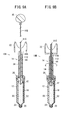
- FIG. 2A is a longitudinal sectional view of the pharmaceutical injection device shown in FIG. 1 in an assembled state
- FIG. 2B is a perspective view of a handle and its surroundings according to a modification
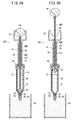
- FIG. 3A is a first diagram illustrating a method of filling a medicine injection device shown in FIG. 1 with a drug
- FIG. 3B is a second diagram illustrating a method of filling the medicine injection device shown in FIG.
- FIG. 4A is a first diagram for explaining a method of discharging air from the cylindrical body of the drug injection device shown in FIG. 1
- FIG. 4B is a diagram illustrating discharging air from the cylindrical body of the drug injection device shown in FIG.
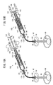
- FIG. 6A is a first diagram illustrating an operation method of the drug injection device illustrated in FIG. 1
- FIG. 6B is a second diagram illustrating an operation method of the drug injection device illustrated in FIG. 1.
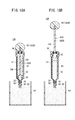
- FIG. 8A is a first diagram illustrating a method of filling a medicine injection device shown in FIG. 7 with a drug
- FIG. 8B is a second diagram illustrating a method of filling the medicine injection device shown in FIG. FIG.
- FIG. 9A is a first view for explaining a method of discharging air from the cylindrical body of the drug injection device shown in FIG. 7, and FIG. 9B discharges air from the cylindrical body of the drug injection device shown in FIG. It is the 2nd figure explaining the method to do. It is a longitudinal cross-sectional view of the chemical injection tool which concerns on 3rd Embodiment of this invention.
- FIG. 11A is a first diagram for explaining the operation of the drug injection device shown in FIG. 10, and FIG. 11B is a second diagram for explaining the operation of the drug injection device shown in FIG. It is a longitudinal cross-sectional view of the chemical injection tool which concerns on 4th Embodiment of this invention.
- 13A is a first diagram illustrating a method for filling a drug injecting device shown in FIG.
- FIG. 13B is a second diagram illustrating a method for filling the drug injecting device shown in FIG.
- FIG. 13C is a view for explaining a method of discharging air from the cylindrical body of the pharmaceutical injection device shown in FIG. 14A is a first diagram illustrating a first operation method of the drug injection device shown in FIG. 12, and FIG. 14B is a second diagram illustrating a first operation method of the drug injection device shown in FIG. FIG.
- FIG. 15A is a first diagram illustrating a second operation method of the drug injection device shown in FIG. 12, and FIG. 15B is a second diagram illustrating a second operation method of the drug injection device shown in FIG. FIG.
- FIG. 16A is a third diagram illustrating a second operation method of the drug injection device illustrated in FIG.
- FIG. 17 It is the 2nd figure explaining the method to discharge
- 22A is a diagram showing a state in which the shaft portion is removed from the head portion in the filling member of the drug injection device shown in FIG. 21 filled with the drug
- FIG. 22B is a drug injection device shown in FIG. 21 filled with the drug.
- FIG. 21 It is a 1st figure explaining the method to discharge
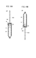
- FIG. 24A is a longitudinal sectional view of a pharmaceutical injection device according to a seventh embodiment of the present invention
- FIG. 24B is a longitudinal sectional view showing a modification of the pharmaceutical injection device shown in FIG. 24A.
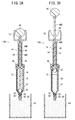
- FIG. 25A is a first diagram for explaining a method of filling a medicine injection device shown in FIG. 24A with a drug
- FIG. 25B is a second diagram for explaining a method of filling the medicine injection device shown in FIG. 24A with a medicine
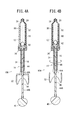
- FIG. FIG. 26A is a first diagram illustrating a method of discharging air from the cylindrical body of the medicine injection device shown in FIG. 24A filled with medicine
- FIG. 26B is a medicine shown in FIG. 24A filled with medicine. It is the 2nd figure explaining the method of discharging
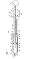
- FIG. 1 is an exploded perspective view showing a pharmaceutical injection device 10A according to the first embodiment of the present invention.
- FIG. 2A is a longitudinal sectional view of the pharmaceutical injection device 10A shown in FIG. 1 in an assembled state.
- the drug injection tool 10A is a medical device used for discharging a drug when a drug (filler, injection material) is injected into a desired injection space. For example, bone cement in percutaneous vertebroplasty. Is used to inject into the bone.
- bone cement such as calcium phosphate bone cement (CPC) or polymethyl methacrylate (PMMA) bone cement
- CPC calcium phosphate bone cement
- PMMA polymethyl methacrylate
- CPC calcium phosphate bone cement
- alumina ceramics alumina ceramics
- Granules made of inorganic materials such as zirconia ceramics and titanium can also be used.
- the drug injection device 10 ⁇ / b> A includes a cylindrical body 12 that is filled with a drug, a pusher 14 that is inserted into a hollow portion of the cylindrical body 12, and a pusher 14 that can advance and retreat. And a filling member 16 inserted therethrough.
- the body portion 18 includes a parallel portion 18a having a constant inner diameter and a tapered portion 18b that decreases in diameter from the tip of the parallel portion 18a toward the tip tube portion 20, and is formed in a hollow cylindrical shape as a whole.
- a scale 19 indicating the amount of the medicine is provided on the outer peripheral surface of the body portion 18.
- the distal end tube portion 20 forms the medicine discharge port 12a and is configured as a luer connector.
- a lock portion 28 that protrudes in the axial direction from the tip portion of the body portion 18 concentrically with the tip tube portion 20 and has an internal thread portion 27 formed on the inner peripheral surface is provided.
- the medicine is injected by such a distal end pipe part 20 and the lock part 28, it can be connected to an extension tube 88 or a bone cement injection needle 92 (see FIG. 6A and the like) described later.
- the flange portion 22 has a non-circular shape.
- the flange portion 22 includes a pair of straight portions 22a that are parallel to each other and a pair of arc portions 22b that connect both ends of the straight portions 22a.
- the non-circular flange portion 22 engages with the cover member 52 such as an ellipse, a polygon, or a shape protruding outward in a part of the circumferential direction. Any shape can be used.
- the constituent material of the cylindrical body 12 is not particularly limited.
- polyolefin such as polypropylene, polyurethane, polyethylene, cyclic polyolefin, polymethylpentene 1, polyester, nylon, polycarbonate, polymethylmethacrylate (PMMA), polyetherimide ( PEI), polyethersulfone, polyetheretherketone (PEEK), fluororesin, polyphenylene sulfide (PPS), polyacetal resin (POM) and other resinous materials, stainless steel and other metallic materials, glass, etc.
- PMMA polymethylmethacrylate
- PEI polyetherimide
- PEEK polyethersulfone
- PES polyetheretherketone
- fluororesin polyphenylene sulfide
- PPS polyacetal resin
- the constituent material of the cylindrical body 12 is substantially transparent in order to ensure internal visibility.
- the pusher 14 includes a shaft 30 that can be inserted into the hollow portion of the cylindrical body 12, and a hollow handle 32 that is provided at the base end of the shaft 30 and has an outward diameter (radially outward).
- the pusher 14 can be displaced in the axial direction relative to the filling member 16 and can be relatively rotated in the circumferential direction.
- the shaft 30 has an insertion hole 30a (see FIG. 2A) penetrating linearly in the axial direction.
- the head portion 31 constituting the distal end portion of the shaft 30 has a tapered shape with a diameter reduced toward the distal end side, and the most advanced surface is an annular distal end surface 31a having a small area.
- the annular tip surface 31 a is a surface perpendicular to the axis of the shaft 30.
- a male thread portion 34 is formed along the axial direction in a predetermined range in the longitudinal direction on the outer peripheral portion of the shaft 30.
- the outer diameter of the male screw portion 34 is smaller than the inner diameter of the body portion 18 of the cylindrical body 12.
- a guide member 36 that can be connected to the cover member 52 is attached to the male screw portion 34. The configuration of the guide member 36 will be described later.
- a groove portion 40 into which the shaft portion 44 of the filling member 16 can enter is provided on the distal end side of the notch portion 38.
- the groove portion 40 has a shape that communicates the inside and outside of the cover portion 32b and opens in the proximal direction of the cover portion 32b.
- the width of the groove portion 40 is larger than the thickness (outer diameter) of the shaft portion 44 of the filling member 16.
- the distal end position of the groove portion 40 may be in the vicinity of the most proximal end portion of the shaft 30.
- the constituent material of the pusher 14 can be selected from those exemplified as the constituent material of the cylindrical body 12 described above.
- the head portion 42 is a portion that constitutes the distal end portion of the filling member 16, and is within the range restricted by the tapered portion 18 b of the cylindrical body 12 and the head portion 31 of the pusher 14 in the cylindrical body 12. It can move in the axial direction.
- a seal member 46 is attached to the head portion 42.
- an annular seal groove 47 (see FIG. 2A) extending in the circumferential direction is formed on the outer periphery of the head portion 42, and a ring-shaped seal member 46 (for example, a silicone O-ring) is formed in the seal groove 47. Is placed.
- Such a seal member 46 slides in the axial direction while being in close contact with the inner peripheral surface of the cylindrical body 12, so that liquid-tightness can be reliably maintained and slidability can be improved.
- the constituent material of the seal member 46 is not particularly limited.
- a gasket made of an elastic resin material may be attached to the tip of the filling member 16.
- the outer diameter of the front end portion of the filling member 16 (in the illustrated example, the outer diameter of the seal member 46 assembled in the head portion 42) is the same as or slightly smaller than the inner diameter of the body portion 18 of the cylindrical body 12, For example, it is set to about 5 to 50 mm, and more preferably set to about 10 to 20 mm. If the outer diameter of the seal member 46 assembled in the head portion 42 is too large, the operation force when rotating the pusher 14 of the drug injection device 10A filled with a high-viscosity drug becomes too large, Operation becomes difficult. In addition, if the outer diameter of the seal member 46 assembled in the head portion 42 is too small, it becomes difficult to maintain liquid tightness with the body portion 18 of the cylindrical body 12.
- the shaft portion 44 is smaller in diameter than the insertion hole 30a provided in the shaft 30 of the pusher 14, and is inserted into the insertion hole 30a so as to be slidable in the axial direction.
- the user grips the gripping portion 45 and sucks it.
- the force when the operation is performed that is, the operation force in the axial direction from the user input to the grip portion 45 is transmitted to the head portion 42 described above. Since the head portion 42 slidably inserted into the cylindrical body 12 is moved in the axial direction, the total length of the shaft portion 44 is longer than the total length of the shaft 30 of the pusher 14.
- the shaft portion 44 can be separated into a first portion 44A on the distal end side and a second portion 44B on the proximal end side at an intermediate position in the axial direction.
- the shaft portion 44 has a fragile portion 48 (see FIG. 2A) at an intermediate position in the axial direction.
- the fragile portion 48 is an annular groove having a V-shaped cross section. That is, the weakened part 48 is a part whose strength is relatively smaller than that of the other part by being formed with a narrower diameter than the other part by the annular groove having a V-shaped cross section. Therefore, the first portion 44 ⁇ / b> A and the second portion 44 ⁇ / b> B can be separated by the fragile portion 48 being broken when a predetermined bending stress or more is applied to the shaft portion 44.
- the second portion 44B is moved at the position of the fragile portion 48. Separated from the first portion 44A.
- the filling member 16 at the end of the air discharge operation is not located at the last retracted position of the movable range, but is located at a position where it has advanced to the tip side to some extent from the last retracted position. Further, the position of the filling member 16 at the end of the air discharge operation depends on the amount of medicine filled in the cylindrical body 12. On the other hand, in order to cause a bending stress to act on the shaft portion 44 and break the shaft portion 44 at the weakened portion 48, the weakened portion 48 needs to be exposed to the outside.
- the fragile portion 48 is positioned closer to the proximal end side than the shaft 30 of the pusher 14 (shaft 30 ).
- the position of the fragile portion 48 is set so that it is exposed behind.
- the structure which makes it possible to separate the first part 44A and the second part 44B is not limited to the configuration by the fragile portion 48 described above.
- the first part 44A and the second part 44B made of different parts are connected by physical engagement such as fitting and screwing, and a tensile stress, bending stress or rotational stress exceeding a predetermined level is applied.
- a configuration in which the connection between the first portion 44A and the second portion 44B is released may be employed.
- the grip portion 45 is a portion that is gripped (pulled) and pulled by the user when filling the cylindrical body 12 with a medicine, and is formed in a flat shape wider than the shaft portion 44 in this embodiment.
- a bottomed recess 50 is provided on the side of the grip 45.
- the concave portions 50 are provided on both surfaces of the grip portion 45.
- the concave portion 50 may be provided only on one side surface of the grip portion 45.
- the shape of the gripping portion 45 may be any shape that can be pulled in the proximal direction when filling the bone cement and can be pressed in the radial direction when the shaft portion 44 is broken. Further, a shape in which a through hole is provided in the side portion may be used. Further, by providing the through hole, the user's finger can be hooked when the filling member 16 is moved backward with respect to the cylindrical body 12.
- the pharmaceutical injection device 10A further includes a cover member 52 that covers the periphery of the cylindrical body 12.
- the cover member 52 has a cylindrical shape with both ends opened, and the cylindrical body 12 can be inserted from the base end side. In the state where the cover member 52 and the guide member 36 are coupled, the cover member 52 is prevented from moving in the axial direction with respect to the cylindrical body 12, but in the state where the cover member 52 and the guide member 36 are separated, the cover member 52 is covered.
- the member 52 can be displaced in the axial direction with respect to the cylindrical body 12.
- the cover member 52 has a length that can substantially cover the cylindrical body 12.
- the distal end (tip tube portion 20) of the cylindrical body 12 is a cover. Projecting from the tip of the member 52.
- the cover member 52 includes a fitting portion 54 that fits (contacts) with the outer peripheral portion of the inserted tubular body 12, and an enlarged diameter portion that has an inner diameter larger than the inner diameter of the fitting portion 54. 56.
- the fitting portion 54 is provided only in a predetermined range constituting the proximal end portion of the cover member 52 and has an inner diameter that is substantially the same as the outer diameter of the cylindrical body 12.
- a female screw portion 58 to which the guide member 36 can be screwed is provided on the inner periphery of the base end portion of the cover member 52.
- the enlarged diameter portion 56 constitutes a portion (a portion other than the proximal end portion) extending from the distal end portion to the vicinity of the proximal end portion in the cover member 52 and has an inner diameter larger than the outer diameter of the cylindrical body 12. For this reason, in a state where the cylindrical body 12 is inserted through the cover member 52, an annular gap 60 (air) extending in the axial direction between the inner peripheral surface of the cover member 52 and the outer peripheral surface of the cylindrical body 12. Layer) is formed.
- the void 60 functions as a heat insulating layer.
- the cover member 52 and the guide member 36 may be integrally formed.
- the bone cement injection needle 92 includes a hollow puncture needle 96 made of, for example, a metal material, and a handle 98 made of, for example, a resin material fixed to the proximal end portion of the puncture needle 96.
- a hollow puncture needle 96 made of, for example, a metal material
- a handle 98 made of, for example, a resin material fixed to the proximal end portion of the puncture needle 96.
- An injection port 94 communicating with the lumen (hollow portion) of the puncture needle 96 is provided on the upper portion of the handle 98.
- One end of the extension tube 88 is provided with a connector 100 that is detachably connected to the injection port 94, and the other end of the extension tube 88 is a connector that is detachable from the distal end tube portion 20 and the lock portion 28 of the cylindrical body 12. 102 is provided.
- the shaft portion 44 has a fragile portion 48 at an intermediate position in the axial direction, and the first portion 44A and the second portion 44B are subjected to a bending stress of a predetermined level or more on the shaft portion 44. At this time, the fragile portion 48 is broken and can be separated.
- a bottomed concave portion 50 (see FIG. 1) is provided on the side portion of the gripping portion 45 of the filling member 16, so that the filling is performed by pressing the concave portion 50 from the side of the gripping portion 45.
- the operation of folding the shaft portion 44 of the member 16 can be easily performed.
- a pressure gauge for the user to check the injection pressure may be provided on a part of the distal end tube portion 20 or the extension tube 88 of the cylindrical body 12 of the drug injection device 10A described above.
- the pusher 14 and the filling member 110 are inserted into the cylindrical body 12 and the cover member 52 and the guide member 36 are connected. Put it in a state. In this case, the pusher 14 is moved to the proximal end side of the movable range, and the filling member 110 is moved to the most distal side of the movable range.
- the suction port 80 is screwed and attached to the lock portion 28 of the cylindrical body 12, and the tip of the suction port 80 is buried in the bone cement 86.
- the attachment of the suction port 80 to the cylindrical body 12 may be performed before the cover member 52 and the guide member 36 are connected.
- the shaft portion 44 of the filling member 110 is connected to the first portion 44A and the second portion.
- the air in the cylindrical body 12 can be discharged to the outside easily, quickly and reliably without the cylindrical body 12 being directed upward. it can.
- FIG. 10 is a longitudinal sectional view of a pharmaceutical injection device 10C according to the third embodiment of the present invention. Note that in the drug injection device 10C according to the third embodiment, elements having the same or similar functions and effects as those of the drug injection device 10A according to the first embodiment are denoted by the same reference numerals, and detailed description thereof is omitted. To do.
- the drug injection device 10C is different from the drug injection device 10A according to the first embodiment described above in the configuration of the filling member 120 and the pusher 122.
- the shaft portion 44 of the filling member 120 is provided with a first convex portion 124 that protrudes outward.
- the first convex portion 124 is an annular protrusion that bulges outward in the radial direction from the other portion of the shaft portion 44, and is provided near the tip of the shaft portion 44.
- the shaft 30 is provided with a second convex portion 126 that protrudes inward and engages with the first convex portion 124.
- the second protrusion 126 is an annular protrusion that bulges radially inward from the other portion of the insertion hole 30 a of the shaft 30, and is provided at the tip of the shaft 30 in this embodiment.
- the outer diameter of the first convex portion 124 is larger than the inner diameter of the second convex portion 126. Therefore, as shown in FIG. 11A, when the filling member 120 is pulled and moved in the proximal direction in order to fill the cylindrical body 12 with a medicine (for example, bone cement 86), the first convex portion 124 and the first protrusion 124 are eventually formed. The two convex portions 126 come into contact.
- the weak part 48 and the first convex part 124 provided on the shaft part 44 and the second convex part 126 provided on the shaft 30 are the weak part when the first convex part 124 and the second convex part 126 contact each other. 48 is set to be exposed from the base end of the shaft 30 to the outside.
- Other portions of the filling member 120 are configured in the same manner as the filling member 16 in the first embodiment.
- Other portions of the pusher 122 are configured in the same manner as the pusher 14 in the first embodiment.
- the medicine injection device 10C configured as described above, in the process of moving the filling member 120 in the proximal direction in order to fill the cylindrical body 12, the first protrusion 124 and the second protrusion When 126 comes into contact, the movement resistance of the filling member 16 increases. And in this position, the weak part 48 provided in the axial part 44 exists in the position exposed outside from the base end of the shaft 30 of the pusher 14. FIG. Accordingly, the position where the shaft portion 44 can be cut is easily recognized by the user.
- the shaft 142 is configured in the same manner as the shaft 30 of the pusher 14 in the first embodiment.
- the handle 144 extends in the proximal direction so as to at least partially cover the second pusher 136 protruding from the proximal end of the shaft 142.
- the handle 144 includes a flange portion 144a extending radially outward from the proximal end portion of the shaft 142, and a cover portion 144b extending from the outer end of the flange portion 144a in the proximal direction.
- the second pusher 136 is inserted through the through-hole 135 of the filling member 134 so as to be displaceable in the axial direction within a restricted range.
- the second pusher 136 has a rod 156 slidably inserted into the through hole 135 of the filling member 134 and a flange portion 158 provided (attached) to the proximal end portion of the rod 156.
- the rod 156 is formed with a smaller diameter than the shaft portion 150 of the filling member 134.
- An axis of the rod 156 with respect to the first pusher 132 is disposed on the outer peripheral surface of a portion of the rod 156 that protrudes from the filling member 134 to the proximal end side with the second pusher 136 displaced to the most proximal side with respect to the filling member 134.
- Scales indicating the position in the direction may be provided at regular intervals.
- the scale is not particularly limited as long as it can be visually recognized by the user.
- the scale may be constituted by a groove extending in the circumferential direction, or may be made of ink (paint) having a color different from that of the rod 156. It may be displayed.
- the enlarged diameter portion 160 whose outer diameter is slightly larger than the other portions is formed on the distal end side of the rod 156.
- a stepped portion 162 is formed by the outer diameter difference between the enlarged diameter portion 160 and a portion closer to the proximal end than the enlarged diameter portion 160 (hereinafter referred to as the narrow diameter portion 161).
- the second pusher 136 is located with respect to the filling member 134 until the end surface (stepped portion 162) on the proximal end side of the enlarged diameter portion 160 and the stepped portion 154 provided on the inner peripheral portion of the filling member 134 are in contact with each other. Can be moved to the base end side.
- a seal member 152 is attached to the outer peripheral portion of the enlarged diameter portion 160 of the rod 156.
- the seal member 152 can slide in a liquid-tight manner in the axial direction along the inner peripheral surface while being in close contact with the inner peripheral surface of the shaft portion 150 of the filling member 134.
- the seal member 152 is in the form of a ring provided on the outer peripheral portion of the enlarged diameter portion 160, but instead of this form, for example, an elastic member attached to the distal end of the enlarged diameter portion 160.
- a gasket made of a resin material may be used.
- the distal end surface of the first pusher 132 becomes the head portion of the filling member 134.
- the filling member 134 is pushed up (advanced) by the first pusher 132 in contact with the base end surface of 148. Then, as shown in FIG. 13C, the air is completely discharged from the cylindrical body 130 by moving the filling member 134 forward by an amount corresponding to the volume of air existing at the end of filling the bone cement 86. Can do.
- the first pusher 132 is rotated, and the filling member 134 is moved to the distal end side with respect to the cylindrical body 130. Then, as the filling member 134 moves toward the distal end side with respect to the tubular body 130, the filling chamber in the tubular body 130 is pressurized to a high pressure, and the bone cement 86 is moved to the distal end pipe portion 20, the extension tube 88, and the bone cement. It is injected into the bone 90 via the injection needle 92. In this case, since the second pusher 136 receives pressure from the bone cement 86 as the first pusher 132 is rotated, the second pusher 136 is brought to the proximal end side with respect to the first pusher 132. Moving.
- the bone cement 86 can be injected with a relatively small operation force, and the head portion 148 of the filling member 134 is compared. Due to the large diameter, a relatively large amount of bone cement 86 can be injected quickly.
- the injection amount of the bone cement 86 per rotation of the first pusher 132 may be set to a predetermined amount (for example, 0.25 to 2 mL).
- the second pusher 136 Since the second pusher 136 has a smaller diameter than the head portion 148 of the filling member 134, a high pressure can be generated with a small operating force, and precise injection can be performed.
- the maximum injection amount of the second pusher 136 may be set to a predetermined amount (for example, 0.5 to 3 mL).
- the pressing operation on the second pusher 136 may be stopped. Then, the pressure in the system is reliably released by the second pusher 136 moving backward with respect to the first pusher 132 and the filling member 134 by the pushing force in the proximal direction from the bone cement 86.
- the injection can be stopped suddenly and accurate injection can be guaranteed.
- the stopcock 170 has a first port 172, a second port 174, and a cock 176. By rotating the cock 176, the passage between the first port 172 and the second port 174 communicates. It is configured as a two-way stopcock that can selectively switch between an open state and a closed state in which the passage between the first port 172 and the second port 174 is blocked.
- Such a stopcock 170 may be provided at either the end of the extension tube 88 on the side connected to the bone cement injection needle 92 or the end on the side connected to the drug injection tool 10D. As shown in the above, when provided at the end of the side connected to the drug injection device 10D, the cock 176 of the stopcock 170 can be rotated outside the X-ray irradiation area when the bone cement 86 is injected. X-ray exposure can be preferably avoided.
- the bone cement 86 filled in the drug injection device 10D is discharged and injected into the bone 90 under X-ray fluoroscopy.
- the second pusher 136 is pressed to make the second pusher 136 cylindrical.
- the body 130 is moved toward the tip side.
- the filling chamber in the cylindrical body 130 is pressurized to a high pressure, and the bone cement 86 is moved to the distal end pipe portion 20.
- the bone 90 is injected through the extension tube 88 and the bone cement injection needle 92. Since the second pusher 136 has a smaller diameter than the head portion 148 of the filling member 134, high pressure can be generated with a small operating force, and precise injection is possible.
- the cock 176 is rotated to close the stopcock 170, and then the first pusher 132 is rotated to bring the first pusher 132 to the tip of the cylindrical body 130. Move to the side.
- the second pusher 136 moves to the proximal end side with respect to the first pusher 132 and the filling member 134.
- the bone cement 86 is prevented from being discharged from the drug injection tool 10D by the stopcock 170, the bone cement 86 is discharged from the drug injection tool 10D as the first pusher 132 is rotated. There is nothing.
- the rotation operation with respect to the first pusher 132 is performed until the second pusher 136 is retracted to the most proximal position.
- the second pusher 136 is pressed to inject the bone cement 86 into the bone 90. Thereafter, similarly to the case of FIG. 16A, the first pusher 132 is rotated again to return the second pusher 136 to the original position.
- the second pusher 136 is rotated by rotating the first pusher 132 after performing an operation of injecting a small amount by pushing the second pusher 136 toward the distal end side.
- the two operations are alternately repeated a plurality of times to inject a target amount of bone cement 86. Therefore, precise injection is possible in all injections.
- the pressure increase in the tubular body 130 due to the pressing operation of the first pusher 132 is insufficient, and it is difficult to move the second pusher 136 backward to the base side. Therefore, it is preferable to use the stopcock 170.
- the filling member 182 includes a head portion 42 that is liquid-tightly inserted into the hollow portion of the cylindrical body 12 on the distal end side of the pusher 180, and a shaft that extends in the proximal direction from the head portion 42 and has a smaller diameter than the head portion 42.
- a portion 186 and a grip 45 provided at the base end of the shaft portion 186 and wider than the shaft portion 186.
- the filling member 182 can be separated into a first portion 182A on the distal end side and a second portion 182B on the proximal end side at a predetermined position between the head portion 42 and the grip portion 45.
- the proximal end of the shaft portion 186 and the distal end of the grip portion 45 are connected to be separable. Accordingly, in the present embodiment, the head portion 42 and the shaft portion 186 constitute a first portion 182A, and the grip portion 45 constitutes a second portion 182B.
- a male screw portion 187 having a smaller diameter than the outer diameter of the shaft portion 186 is provided at the proximal end of the shaft portion 186, and a female screw portion 189 is provided at the grip portion 45.
- a female screw portion 189 may be provided at the base end of the shaft portion 186 and a male screw portion 187 may be provided at the distal end of the grip portion 45.
- the structure which makes it possible to separate the first part 182A and the second part 182B is not limited to the above-described screwed structure.
- the first part 182A and the second part 182B are connected by the fitting structure of the convex part and the concave part and a tensile stress, bending stress, or rotational stress of a predetermined level or more acts, the first part 182A and the second part 182B.
- a configuration in which the connection with the is released can also be adopted.
- the gripping portion 45 is the base end in a state where the filling member 182 is inserted into the tubular body 12 and the pusher 180 is separated from the tubular body 12 and the filling member 182.
- the head portion 42 moves in the proximal direction with respect to the cylindrical body 12.
- the medicine injection device 10E the first part 182A and the second part 182B are separated, the first part 182A is inserted into the cylindrical body 12, and the female screw part 61 and the male screw part 34 are screwed together.
- the pusher 180 pushes the head part 42, and the head part 42 moves in the distal direction with respect to the cylindrical body 12.
- the suction port 80 is screwed and attached to the lock portion 28 of the cylindrical body 12, and the tip of the suction port 80 is buried in the bone cement 86.
- the attachment of the suction port 80 to the cylindrical body 12 may be performed before the cover member 52 and the guide member 36 are connected.
- the grip portion 45 is gripped, and the filling member 182 is based on the cylindrical body 12.
- the bone cement 86 is sucked into the cylindrical body 12 through the suction port 80 and the distal end tube portion 20 as the filling member 182 moves. Thereby, the bone cement 86 is filled in the cylindrical body 12.
- the drug injector 10E and a bone cement injection needle 92 punctured by the patient are connected via an extension tube 88. Then, by rotating the pusher 180 under fluoroscopy, the bone cement 86 is discharged from the cylindrical body 12 and injected into the patient's bone 90 through the extension tube 88 and the bone cement injection needle 92. .
- the length of the filling member 182 is the length of the pusher 180. Not subject to restrictions. For this reason, the length of the filling member 182 can be shortened, and thereby the weight of the medicine injection device 10E as a whole can be reduced.
- the second portion 182B (the gripping portion 45 in this embodiment) of the filling member 182 is separated from the first portion 182A.
- the filling member 182 does not interfere with the operation, and the operability is excellent.
- the pusher 190 has a shaft 195 having a solid structure and a handle 184.
- the pusher 190 is configured in the same manner as the pusher 180 shown in FIG. 17 except that the shaft 195 has a solid structure.
- the filling member 194 includes a head portion 42 that is liquid-tightly inserted into the hollow portion of the cylindrical body 12 on the distal end side of the pusher 190, and a shaft that extends from the head portion 42 in the proximal direction and has a smaller diameter than the head portion 42.
- a portion 196 and a grip 45 provided at the base end of the shaft portion 196 and wider than the shaft portion 196.
- tip of the axial part 196 are connected so that isolation
- a female screw portion 198 is provided at the base end of the head portion 42, a male screw portion 197 is provided at the outer periphery of the tip of the shaft portion 196, and the male screw portion 197 and the female screw portion 198 are screwed.
- the head portion 42 and the shaft portion 196 are detachably connected.
- a male screw portion 197 may be provided at the base end of the head portion 42 and a female screw portion 198 may be provided at the tip of the shaft portion 196.
- the structure that enables the head part 42 and the shaft part 196 to be separated is not limited to the above-described screwed structure.
- the head portion 42 and the shaft portion 196 are connected by the fitting structure of the convex portion and the concave portion and a tensile stress or a rotational stress exceeding a predetermined level is applied, the connection between the head portion 42 and the shaft portion 196 is released. Configurations can also be employed.
- the length of the shaft portion 196 is such that the grip portion 45 is pushed in the distal direction, so that the head portion 42 reaches a position where the tip tapered surface of the head portion 42 of the filling member 194 contacts the inner surface of the tapered portion 18b of the cylindrical body 12. Is set to be movable in the distal direction with respect to the cylindrical body 12.
- the head portion 42 and the shaft portion 196 are separated.
- the head part 42 and the shaft part 196 are separated by gripping the shaft part 196 or the grip part 45 and rotating it in the circumferential direction.
- a certain amount of frictional force acts between the seal member 46 mounted on the outer peripheral portion of the head portion 42 and the inner peripheral surface of the cylindrical body 12, even if the shaft portion 196 is rotated.
- the head portion 42 does not rotate in the cylindrical body 12.
- the front end of the cylindrical body 12 is turned upward, and the apparatus waits for a while in this state. Then, the air gradually rises in the bone cement 86 and finally goes out above the bone cement 86.
- the timing for separating the head portion 42 and the shaft portion 196 may be during or after the air is moved to the distal end side of the cylindrical body 12.
- the male thread portion 34 of the pusher 190 is screwed into the female thread portion 61 of the guide member 36 as shown in FIG. Then, the pusher 190 is rotated in the circumferential direction to move forward. Then, the distal end surface of the pusher 190 comes into contact with the proximal end surface of the head portion 42 of the filling member 194, and the filling member 194 is pushed up (advanced) by the pusher 190. Then, the air can be completely discharged from the cylindrical body 12 by advancing the filling member 194 by an amount corresponding to the volume of air existing at the end of filling the bone cement 86.
- the drug injector 10F and a bone cement injection needle 92 punctured by the patient are connected via an extension tube 88. Then, by rotating the pusher 190 under fluoroscopy, the bone cement 86 is discharged from the cylindrical body 12 and injected into the patient's bone 90 through the extension tube 88 and the bone cement injection needle 92. .
- the length of the filling member 194 can be shortened, similarly to the pharmaceutical injection device 10E, thereby reducing the weight of the entire pharmaceutical injection device 10F. Can do. Further, when the pusher 190 is rotated to discharge the medicine from the cylindrical body 12, the base end of the filling member 194 does not protrude from the pusher 190, so that the filling member 194 obstructs the operation. The operability is excellent.
- the head portion 42 and the shaft portion 196 can be separated, and the pusher 190 is inserted into the cylindrical body 12 after the head portion 42 and the shaft portion 196 are separated. It is not necessary to provide the pusher 190 with a hole for inserting the portion 196. Therefore, the configuration of the pusher 190 can be simplified.
- FIG. 24A is a longitudinal sectional view of a pharmaceutical injection device 10G according to the seventh embodiment of the present invention.
- the same or similar components as those of the pharmaceutical injection device 10A according to the first embodiment are denoted by the same reference numerals, and detailed description thereof is omitted.
- the pharmaceutical injection device 10G is different from the pharmaceutical injection device 10A according to the first embodiment in the configuration of the pusher 210 and the filling member 200.
- the pusher 210 can be inserted into the hollow portion of the cylindrical body 12, and has a shaft 212 provided with a male screw portion 34 on the outer peripheral portion and an insertion hole 214 penetrating in the axial direction, and a base end of the shaft 212. And a hollow handle 184 having a diameter increased outward (radially outward).
- the pusher 210 can be displaced in the axial direction with respect to the filling member 200 and can be relatively rotated in the circumferential direction.
- the outer diameter of the head portion 213 of the shaft 212 is smaller than the inner diameter of the female screw portion 61 provided in the guide member 36. For this reason, the head portion 213 of the shaft 212 can be inserted in the axial direction inside the female screw portion 61 of the guide member 36.
- An inner projecting portion 199 projecting inward is provided on the inner periphery of the tip of the pusher 210.
- the inward protruding portion 199 is annular, but may be divided into a plurality in the circumferential direction.
- the filling member 200 includes a head portion 42 that is liquid-tightly inserted into the hollow portion of the cylindrical body 12 on the distal end side of the pusher 210, and a shaft that extends in the proximal direction from the head portion 42 and has a smaller diameter than the head portion 42. Part 202.
- the shaft portion 202 is inserted into an insertion hole 214 provided in the shaft 212 of the pusher 210.
- the length of the shaft portion 202 is such that the pusher 210 is displaced to the most distal side with respect to the filling member 200 (the proximal end surface of the head portion 42 and the distal end surface of the shaft 212 are in contact).
- the base end is set so as not to protrude from the base end of the shaft 212 (the base end of the shaft portion 202 is in the insertion hole 214).
- An outward projecting portion 204 projecting outward is provided at the proximal end of the shaft portion 202.
- the outward projecting portion 204 is annular, but may be divided into a plurality of portions in the circumferential direction.
- the outer diameter of the outer protrusion 204 is smaller than the inner diameter of the inner protrusion 199. Therefore, when the pusher 210 is moved to the proximal end side with respect to the filling member 200, the inward protrusion 199 and the outer protrusion 204 are engaged with each other, so that the shaft portion 202 of the filling member 200 is pushed by the pusher 210. Slipping out of the tip of the shaft 212 is prevented.
- a male screw portion 208 (first screw portion) is provided on the outer peripheral portion of the base end of the shaft portion 202, and a female screw that can be screwed to the inner peripheral portion of the tip end of the shaft 212.
- the pusher 210 and the filling member 200 may be configured to be connectable by providing a screw portion 206 (second screw portion) and screwing the male screw portion 208 and the female screw portion 206 together. According to this configuration, it is possible to transmit the axial force from the pusher 210 to the filling member 200 not only in the proximal direction but also in the distal direction.
- the filling member 200 is located on the most distal side with respect to the cylindrical body 12, and the screwing of the female screw portion 61 and the male screw portion 34 is released.
- the pusher 210 can pull the filling member 200 at least in the proximal direction in a state where the pusher 210 is retracted from the cylindrical body 12 to the position where the pusher 210 is moved.
- the gripping portion 45 is pulled in the proximal direction in a state where the screwing of the female screw portion 61 and the male screw portion 34 is released, so that the head portion 42 is attached to the cylindrical body 12. On the other hand, it moves in the proximal direction.
- the pusher 210 when the pusher 210 is rotated in a state where the female screw part 61 and the male screw part 34 are screwed together, the pusher 210 pushes the head part 42, and the head part 42 becomes the cylinder. It moves in the distal direction relative to the body 12.
- the suction port 80 is screwed and attached to the lock portion 28 of the cylindrical body 12, and the tip of the suction port 80 is buried in the bone cement 86.
- the attachment of the suction port 80 to the cylindrical body 12 may be performed before the cover member 52 and the guide member 36 are connected.
- the handle 184 is gripped with the distal end portion of the suction port 80 buried in the bone cement 86 in the container 84, and the pusher 210 is proximal to the tubular body 12.
- the filling member 200 is pulled and moved in the proximal direction by the engaging action of the inward protrusion 199 and the outward protrusion 204.
- the bone cement 86 is sucked into the cylindrical body 12 through the suction port 80 and the distal end tube portion 20. Thereby, the bone cement 86 is filled in the cylindrical body 12.
- the pusher 210 When it is confirmed that the air has moved above the bone cement, as shown in FIG. 26B, the pusher 210 is moved in the distal direction, and the male screw portion 34 of the pusher 210 is screwed onto the female screw portion 61 of the guide member 36.
- the pusher 210 is rotated in the circumferential direction with respect to the cylindrical body 12 and moved forward. Then, the distal end surface of the pusher 210 comes into contact with the proximal end surface of the head portion 42 of the filling member 200, and the filling member 200 is pushed up (moved forward) by the pusher 210.
- the air can be completely discharged from the cylindrical body 12 by advancing the filling member 200 by an amount corresponding to the volume of air existing at the end of filling the bone cement 86.
- the drug injector 10G and a bone cement injection needle 92 punctured by the patient are connected via an extension tube 88. Then, by rotating the pusher 210 under fluoroscopy, the bone cement 86 is discharged from the cylindrical body 12 and injected into the patient's bone 90 through the extension tube 88 and the bone cement injection needle 92. .
- the medicine injection device 10G configured as described above, the medicine is filled into the cylindrical body 12 by pulling the pusher 210. Therefore, the length of the filling member 200 is the length of the pusher 210. Not restricted. For this reason, the length of the filling member 200 can be shortened, and thereby the weight of the drug injection device 10G can be reduced as a whole. Further, when the pusher 210 is rotated to discharge the medicine from the cylindrical body 12, the base end of the filling member 200 does not protrude from the base end of the pusher 210, so that the filling member 200 obstructs the rotation operation. The operability is excellent.
- an outward projecting portion 204 is provided on the proximal end side of the shaft portion 202
- an inward projecting portion 199 is provided on the distal end side of the pusher 210
- the pusher 210 is against the filling member 200.
- the outer protrusion 204 and the inward protrusion 199 engage with each other when the base end moves to a predetermined position.
- the outward projecting portion 204 and the inward projecting portion 199 can be obtained simply by pulling the pusher 210 in the proximal direction in a state in which the male screw portion 34 and the female screw portion 61 are disengaged.
- the filling member 200 can be moved in the proximal direction with respect to the cylindrical body 12.
- the cylindrical body 12 is filled when the medicine is filled.
- the pushing member 210 can be pushed to advance the filling member 200, which is convenient.
- the coupling structure of the guide member 36 (138) and the cover member 52 (140) is screw fitting, but is not limited to this, and other coupling structures, for example, a cover An engagement piece that protrudes outward is provided at the base end of the member 52 (140), and a groove portion that can be fitted to the engagement piece is provided in the guide member 36 (138), and the cover member 52 (140) and the guide are provided.
- the guide member 36 (138) is fixed to the cylindrical body 12 (130) by coupling the cover member 52 (140) and the guide member 36 (138).
- the configuration is not limited thereto, and a configuration in which the guide member 36 (138) is directly fixed to the cylindrical body 12 (130) may be employed.
Landscapes
- Health & Medical Sciences (AREA)
- Life Sciences & Earth Sciences (AREA)
- Public Health (AREA)
- General Health & Medical Sciences (AREA)
- Veterinary Medicine (AREA)
- Engineering & Computer Science (AREA)
- Biomedical Technology (AREA)
- Heart & Thoracic Surgery (AREA)
- Surgery (AREA)
- Animal Behavior & Ethology (AREA)
- Orthopedic Medicine & Surgery (AREA)
- Molecular Biology (AREA)
- Medical Informatics (AREA)
- Nuclear Medicine, Radiotherapy & Molecular Imaging (AREA)
- Vascular Medicine (AREA)
- Anesthesiology (AREA)
- Hematology (AREA)
- Infusion, Injection, And Reservoir Apparatuses (AREA)
- Surgical Instruments (AREA)
Priority Applications (2)
| Application Number | Priority Date | Filing Date | Title |
|---|---|---|---|
| JP2014515454A JP6023185B2 (ja) | 2012-05-17 | 2012-09-27 | 薬剤注入具 |
| PCT/JP2012/074831 WO2013171922A1 (fr) | 2012-05-17 | 2012-09-27 | Dispositif d'injection d'agent médical |
Applications Claiming Priority (3)
| Application Number | Priority Date | Filing Date | Title |
|---|---|---|---|
| JPPCT/JP2012/062699 | 2012-05-17 | ||
| PCT/JP2012/062699 WO2013171886A1 (fr) | 2012-05-17 | 2012-05-17 | Dispositif d'injection d'agent médical |
| PCT/JP2012/074831 WO2013171922A1 (fr) | 2012-05-17 | 2012-09-27 | Dispositif d'injection d'agent médical |
Publications (1)
| Publication Number | Publication Date |
|---|---|
| WO2013171922A1 true WO2013171922A1 (fr) | 2013-11-21 |
Family
ID=49583328
Family Applications (2)
| Application Number | Title | Priority Date | Filing Date |
|---|---|---|---|
| PCT/JP2012/062699 Ceased WO2013171886A1 (fr) | 2012-05-17 | 2012-05-17 | Dispositif d'injection d'agent médical |
| PCT/JP2012/074831 Ceased WO2013171922A1 (fr) | 2012-05-17 | 2012-09-27 | Dispositif d'injection d'agent médical |
Family Applications Before (1)
| Application Number | Title | Priority Date | Filing Date |
|---|---|---|---|
| PCT/JP2012/062699 Ceased WO2013171886A1 (fr) | 2012-05-17 | 2012-05-17 | Dispositif d'injection d'agent médical |
Country Status (2)
| Country | Link |
|---|---|
| JP (1) | JP6023185B2 (fr) |
| WO (2) | WO2013171886A1 (fr) |
Cited By (2)
| Publication number | Priority date | Publication date | Assignee | Title |
|---|---|---|---|---|
| IT201700010432A1 (it) * | 2017-01-31 | 2018-07-31 | Accademind S R L | Dispositivo di iniezione di cemento osseo |
| EP3815639A1 (fr) * | 2019-10-30 | 2021-05-05 | Sulzer Mixpac AG | Mécanisme de distribution et procédé de distribution de matériau à l'aide d'un mécanisme de distribution |
Families Citing this family (2)
| Publication number | Priority date | Publication date | Assignee | Title |
|---|---|---|---|---|
| KR102355067B1 (ko) * | 2013-12-05 | 2022-01-24 | 조나단 파이벨 | 뼈의 융합, 안정화 및/또는 고정을 위한 시스템, 방법 및 장치와 함께 사용하기 위한 타겟팅 디바이스 |
| KR101904157B1 (ko) * | 2017-06-13 | 2018-10-05 | 전북대학교병원 | 골 고정 보강 수술에 적합한 골 고정부재 및 이를 포함하는 시스템 |
Citations (6)
| Publication number | Priority date | Publication date | Assignee | Title |
|---|---|---|---|---|
| JPS5628770A (en) * | 1979-07-30 | 1981-03-20 | Leveen Harry H | Injector |
| JPH02193677A (ja) * | 1988-10-03 | 1990-07-31 | Ken Heimreid | 計量/混合注射器 |
| JPH0623054A (ja) * | 1992-04-07 | 1994-02-01 | C R Bard Inc | 血管形成術の用途に適応される選択的に制御可能な膨張‐収縮装置 |
| JP2009534087A (ja) * | 2006-04-21 | 2009-09-24 | セウォン セロンテック カンパニー リミテッド | 注射器のピストンの操作装置 |
| JP2010207379A (ja) * | 2009-03-10 | 2010-09-24 | Jms Co Ltd | 注入器 |
| JP2011072386A (ja) * | 2009-09-29 | 2011-04-14 | Terumo Corp | 薬剤注入具 |
-
2012
- 2012-05-17 WO PCT/JP2012/062699 patent/WO2013171886A1/fr not_active Ceased
- 2012-09-27 JP JP2014515454A patent/JP6023185B2/ja active Active
- 2012-09-27 WO PCT/JP2012/074831 patent/WO2013171922A1/fr not_active Ceased
Patent Citations (6)
| Publication number | Priority date | Publication date | Assignee | Title |
|---|---|---|---|---|
| JPS5628770A (en) * | 1979-07-30 | 1981-03-20 | Leveen Harry H | Injector |
| JPH02193677A (ja) * | 1988-10-03 | 1990-07-31 | Ken Heimreid | 計量/混合注射器 |
| JPH0623054A (ja) * | 1992-04-07 | 1994-02-01 | C R Bard Inc | 血管形成術の用途に適応される選択的に制御可能な膨張‐収縮装置 |
| JP2009534087A (ja) * | 2006-04-21 | 2009-09-24 | セウォン セロンテック カンパニー リミテッド | 注射器のピストンの操作装置 |
| JP2010207379A (ja) * | 2009-03-10 | 2010-09-24 | Jms Co Ltd | 注入器 |
| JP2011072386A (ja) * | 2009-09-29 | 2011-04-14 | Terumo Corp | 薬剤注入具 |
Cited By (2)
| Publication number | Priority date | Publication date | Assignee | Title |
|---|---|---|---|---|
| IT201700010432A1 (it) * | 2017-01-31 | 2018-07-31 | Accademind S R L | Dispositivo di iniezione di cemento osseo |
| EP3815639A1 (fr) * | 2019-10-30 | 2021-05-05 | Sulzer Mixpac AG | Mécanisme de distribution et procédé de distribution de matériau à l'aide d'un mécanisme de distribution |
Also Published As
| Publication number | Publication date |
|---|---|
| JPWO2013171922A1 (ja) | 2016-01-07 |
| JP6023185B2 (ja) | 2016-11-09 |
| WO2013171886A1 (fr) | 2013-11-21 |
Similar Documents
| Publication | Publication Date | Title |
|---|---|---|
| US7604618B2 (en) | High pressure injection syringe | |
| CN101252960B (zh) | 注射装置 | |
| US8412310B2 (en) | Locking syringe with integrated bias member | |
| CN101466425B (zh) | 具有可缩回的针的注射装置 | |
| US20120016296A1 (en) | Autoinjector with mixing means | |
| JP5385074B2 (ja) | 薬剤注入具 | |
| CN101939038A (zh) | 注射器 | |
| JP6023185B2 (ja) | 薬剤注入具 | |
| JPH06190038A (ja) | 皮下注射器 | |
| JP2010523162A (ja) | プランジャーフランジを順次移動させるシリンジ | |
| WO2012066905A1 (fr) | Dispositif d'injection de médicament | |
| CA2539785A1 (fr) | Seringue de rincage a bouchon anti-reflux | |
| US11832862B2 (en) | Methods of delivering bone cement using an access cannula with valve | |
| KR20210048662A (ko) | 주사기 | |
| WO2013141187A1 (fr) | Dispositif d'injection de médicament | |
| DK2788056T3 (en) | A sharp return device | |
| EP2258423B1 (fr) | Seringue réutilisable avec ampoule et aiguille rétractable | |
| KR20180037184A (ko) | 유압 압출 시스템 | |
| JP2015066070A (ja) | 薬剤注入具 | |
| US20120232480A1 (en) | Retractable Syringe with Conical Frustum Tip | |
| JP4874728B2 (ja) | 補填材充填器具 | |
| JP7704737B2 (ja) | 硬膜外腔内の針の検出及び配置のための硬膜外デバイス | |
| WO2013141188A1 (fr) | Dispositif d'injection de médicament | |
| JP2007307063A (ja) | 採血管ホルダー | |
| CA3052390C (fr) | Dispositif d'administration de medicament |
Legal Events
| Date | Code | Title | Description |
|---|---|---|---|
| 121 | Ep: the epo has been informed by wipo that ep was designated in this application |
Ref document number: 12876927 Country of ref document: EP Kind code of ref document: A1 |
|
| ENP | Entry into the national phase |
Ref document number: 2014515454 Country of ref document: JP Kind code of ref document: A |
|
| NENP | Non-entry into the national phase |
Ref country code: DE |
|
| 122 | Ep: pct application non-entry in european phase |
Ref document number: 12876927 Country of ref document: EP Kind code of ref document: A1 |