WO2013171990A1 - Dispositif de chauffage à micro-ondes - Google Patents
Dispositif de chauffage à micro-ondes Download PDFInfo
- Publication number
- WO2013171990A1 WO2013171990A1 PCT/JP2013/002864 JP2013002864W WO2013171990A1 WO 2013171990 A1 WO2013171990 A1 WO 2013171990A1 JP 2013002864 W JP2013002864 W JP 2013002864W WO 2013171990 A1 WO2013171990 A1 WO 2013171990A1
- Authority
- WO
- WIPO (PCT)
- Prior art keywords
- microwave
- waveguide
- openings
- heating chamber
- heated
- Prior art date
- Legal status (The legal status is an assumption and is not a legal conclusion. Google has not performed a legal analysis and makes no representation as to the accuracy of the status listed.)
- Ceased
Links
Images


Classifications
-
- H—ELECTRICITY
- H05—ELECTRIC TECHNIQUES NOT OTHERWISE PROVIDED FOR
- H05B—ELECTRIC HEATING; ELECTRIC LIGHT SOURCES NOT OTHERWISE PROVIDED FOR; CIRCUIT ARRANGEMENTS FOR ELECTRIC LIGHT SOURCES, IN GENERAL
- H05B6/00—Heating by electric, magnetic or electromagnetic fields
- H05B6/64—Heating using microwaves
- H05B6/70—Feed lines
- H05B6/707—Feed lines using waveguides
-
- H—ELECTRICITY
- H05—ELECTRIC TECHNIQUES NOT OTHERWISE PROVIDED FOR
- H05B—ELECTRIC HEATING; ELECTRIC LIGHT SOURCES NOT OTHERWISE PROVIDED FOR; CIRCUIT ARRANGEMENTS FOR ELECTRIC LIGHT SOURCES, IN GENERAL
- H05B6/00—Heating by electric, magnetic or electromagnetic fields
- H05B6/64—Heating using microwaves
- H05B6/70—Feed lines
- H05B6/707—Feed lines using waveguides
- H05B6/708—Feed lines using waveguides in particular slotted waveguides
-
- H—ELECTRICITY
- H05—ELECTRIC TECHNIQUES NOT OTHERWISE PROVIDED FOR
- H05B—ELECTRIC HEATING; ELECTRIC LIGHT SOURCES NOT OTHERWISE PROVIDED FOR; CIRCUIT ARRANGEMENTS FOR ELECTRIC LIGHT SOURCES, IN GENERAL
- H05B6/00—Heating by electric, magnetic or electromagnetic fields
- H05B6/64—Heating using microwaves
- H05B6/72—Radiators or antennas
- H05B6/725—Rotatable antennas
Definitions
- the present invention relates to a microwave heating apparatus such as a microwave oven that radiates microwaves to an object to be heated and performs dielectric heating.
- a microwave oven which is a typical microwave heating device, supplies microwaves radiated from a magnetron, which is a typical microwave generation means, to the inside of a metal heating chamber via a waveguide.
- the object to be heated is dielectrically heated. Therefore, if the microwave electromagnetic field distribution in the heating chamber is not uniform, the object to be heated cannot be heated uniformly.
- a structure for rotating the object to be heated by rotating a table on which the object to be heated is rotated, or an antenna that emits microwaves while the object to be heated is fixed.
- a method of heating the object to be heated by changing the direction of the microwave radiated to the object to be heated by using some kind of driving mechanism such as a configuration in which the object is rotated has been common.
- Patent Document 1 includes an X-shaped circular polarization intersecting on the waveguide 1 as shown in FIG. A configuration using a wave aperture 2 is shown.
- Patent Document 2 As shown in FIG. 13, two rectangular slit-like openings 3 and 4 extending in a direction orthogonal to each other on the waveguide 1 are opposed to each other. A configuration is shown that is spaced apart. Furthermore, in Japanese Patent Application Laid-Open No. 2005-235772 (Patent Document 3), as shown in FIG. 14, a notch 6 is formed in a plane portion of the patch antenna 5 coupled to the waveguide 1 to cause circular polarization. The configuration to be generated is shown.
- Patent Document 1 has a rotating body called a phase shifter 7 at the end of the waveguide 1 as shown in FIG. 12, and Patent Document 2 has a turntable (not shown) for rotating an object to be heated.
- Patent Document 3 describes a configuration in which the patch antenna 5 is also rotated in addition to the turntable 8 to be used as a stirrer.
- Patent Documents 1 to 3 describes that a drive mechanism can be made unnecessary if circularly polarized waves are used. This means that if a drive mechanism is not provided by radiation of only circularly polarized waves, a structure having a general drive mechanism, such as a structure for rotating a table on which an object to be heated is placed, a structure for rotating an antenna, etc. Compared to the case, the stirring of the microwave is insufficient and the uniformity is inferior.
- This invention solves the subject in the above-mentioned conventional microwave heating apparatus, and it aims at providing the microwave heating apparatus which can heat a to-be-heated object uniformly, without using a drive mechanism.
- the microwave heating apparatus is: A heating chamber for storing an object to be heated; A microwave generator for generating microwaves; A waveguide for transmitting microwaves; A plurality of microwave radiating portions for radiating microwaves from the waveguide into the heating chamber,
- the heating chamber has a radiation region in which microwaves from the plurality of microwave radiation parts are radiated, and the radiation region has a length approximately twice the guide wavelength in the transmission direction of the waveguide, At least two of the microwave radiating portions are provided at positions separated from each other by a wavelength substantially in the tube in the transmission direction of the waveguide, and are arranged symmetrically with respect to a center line orthogonal to the transmission direction in the radiation region.
- the microwave heating apparatus of the present invention can provide a microwave heating apparatus that can uniformly heat an object to be heated without using a drive mechanism.
- the perspective view which shows the whole structure of the microwave heating apparatus of Embodiment 1 which concerns on this invention.
- the main part in the microwave heating device of Embodiment 1 is shown typically, (a) Plan sectional view and (b) Front sectional view The figure explaining the positional relationship of the to-be-heated material and opening in the microwave heating apparatus of Embodiment 1.
- the main part in the microwave heating device of Embodiment 3 concerning the present invention is shown typically, (a) plane sectional view and (b) front sectional view It is a figure explaining the state which the mounting base in the microwave heating apparatus of Embodiment 3 shifted
- the microwave heating apparatus is A heating chamber for storing an object to be heated; A microwave generator for generating microwaves; A waveguide for transmitting microwaves; A plurality of microwave radiating portions for radiating microwaves from the waveguide into the heating chamber,
- the heating chamber has a radiation region in which microwaves from the plurality of microwave radiation parts are radiated, and the radiation region has a length approximately twice the guide wavelength in the transmission direction of the waveguide, At least two of the microwave radiating portions are provided at positions separated from each other by a wavelength substantially in the tube in the transmission direction of the waveguide, and are arranged symmetrically with respect to a center line orthogonal to the transmission direction in the radiation region. Has been.
- At least two microwave radiating portions that are separated by the in-tube wavelength are radiation regions having a length approximately twice the in-tube wavelength. Are arranged symmetrically with respect to the center line orthogonal to the transmission direction, each of the two microwave radiating portions is provided at an intermediate position from the center to both ends of the radiation region. Further, since the two microwave radiating portions are separated by the in-tube wavelength, the positional relationship is always in the same phase, and the same amount of microwaves can always be radiated from the inside of the waveguide toward the heating chamber.
- the microwave heating apparatus configured as described above always radiates an equal amount of microwaves from two microwave radiating portions located just in the middle from the center to both ends of the radiation region. Therefore, microwaves can be radiated uniformly over the entire area of the radiation region, and the object to be heated can be uniformly heated without using a drive mechanism.
- the radiation region according to the first aspect is defined by a mounting table on which an object to be heated is mounted.
- the microwave heating apparatus according to the second aspect of the present invention configured as described above always has the same amount of microwaves from the two microwave radiating portions provided at the intermediate positions from the center to both ends of the mounting table. Since waves can be radiated, microwaves can be radiated uniformly over the entire surface of the mounting table, and the object to be heated can be uniformly heated without using a drive mechanism. .
- the radiation region according to the first aspect is defined by a space between opposing wall surfaces of the heating chamber.
- the microwave heating apparatus according to the third aspect of the present invention configured as described above always has the same amount of microwaves from the two microwave radiating portions provided at the intermediate positions from the center to both ends of the heating chamber. Since waves can be radiated, microwaves can be radiated uniformly over the entire heating chamber, and the object to be heated can be uniformly heated without using a driving mechanism. .
- the radiation region of the first aspect is disposed at a position where the microwave radiation part is provided and above the microwave radiation part. It is defined by the bottom space between the position of the mounting table.
- the microwave heating device according to the fourth aspect of the present invention configured as described above is provided in two positions just between the center and both ends of the bottom space between the microwave radiating unit and the mounting table. Since the same amount of microwaves can always be radiated from the microwave radiating part, it is possible to radiate the microwaves uniformly over the entire bottom space between the microwave radiating part and the mounting table. The object to be heated can be heated uniformly without using a drive mechanism.
- the microwave heating apparatus In the microwave heating apparatus according to the fifth aspect of the present invention, at least two of the microwave radiating portions in any one of the first to fourth aspects are generated in the waveguide. It is configured to be arranged near the antinode of the standing wave.
- the microwave heating apparatus configured as described above, since the electric field is strong in the antinode of the standing wave in the waveguide, the amount of radiation from the microwave radiating unit located in the vicinity thereof is reduced.
- the number of the microwaves can be increased, and the microwaves can be stably supplied from the two microwave radiation portions into the heating chamber.
- the microwave heating device according to the fifth aspect of the present invention can radiate microwaves uniformly from the end to the end of the radiation region as intended, without using a drive mechanism.
- the object to be heated can be heated uniformly.
- At least two of the microwave radiating portions in any one of the first to fifth aspects are the transmission direction of the waveguide.
- the other microwave radiating portion is provided in a region between at least two of the microwave radiating portions.
- a microwave heating device for example, when a waveguide with a long in-tube wavelength is selected, there is a concern that the distance between the microwave radiating sections will be long (the radiation area will be wide) and the center will be difficult to be heated.
- the structure has another microwave radiating portion between the microwave radiating portions, heating in the center can be promoted, and the object to be heated Can be heated uniformly.
- heating efficiency is improved by promoting heating in the center of the heating chamber. Can also be improved.
- microwave heating apparatus In the microwave heating apparatus according to the seventh aspect of the present invention, at least two of the microwave radiating portions in any one of the first to sixth aspects are in the width direction of the waveguide. The two are arranged side by side.
- the microwave heating device according to the seventh aspect of the present invention configured as described above is configured not only to make the transmission direction of the waveguide uniform, but also to easily diffuse the microwave in the width direction of the waveguide. Thus, microwaves can be emitted uniformly to the entire heating chamber, and the object to be heated can be heated uniformly.
- the microwave radiating unit according to any one of the first to seventh aspects is configured with an opening shape that radiates circularly polarized waves. ing.
- the microwave heating apparatus according to the eighth aspect of the present invention configured as described above generates an electric field that rotates 360 degrees in all directions peculiar to circular polarization around the microwave radiating unit, and the microwave radiating unit Microwaves are radiated into the heating chamber so as to make a vortex from the center, and the circumferential direction can be heated uniformly.
- microwaves can be radiated uniformly over the entire heating chamber, and the object to be heated can be heated uniformly.
- the microwave radiating portion for radiating circularly polarized waves according to the eighth aspect is configured by an approximately X-shaped opening in which two long holes intersect. ing.
- the thus configured microwave heating apparatus according to the ninth aspect of the present invention can reliably radiate circularly polarized waves from the waveguide with a simple configuration.
- a microwave oven will be described.
- the microwave oven is an example, and the microwave heating apparatus of the present invention is not limited to the microwave oven, and uses dielectric heating.
- a microwave heating device such as a garbage processing machine or a semiconductor manufacturing device.
- the present invention is not limited to the specific configurations of the following embodiments, and includes configurations based on similar technical ideas.
- FIG. 1 and 2 are diagrams for explaining the microwave heating apparatus according to the first embodiment of the present invention.
- FIG. 1 is a perspective view showing the overall configuration of the microwave heating apparatus of the first embodiment
- FIG. 2 is a microwave generation section, a waveguide, and a heating chamber, which are main parts of the microwave heating apparatus of the first embodiment. Etc. are schematically shown.
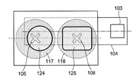
- FIG. 2 (a) is a sectional view of the heating chamber and the like viewed from above, and (b) is a sectional view of the heating chamber viewed from the front.
- a microwave oven 101 that is a typical microwave heating apparatus includes a heating chamber 102 that can store food (not shown) that is a typical object to be heated, and a typical microwave generator that generates microwaves.
- the microwave radiating portions 105 and 106 in the first embodiment are configured by two openings 105 and 106 formed on the upper surface of the waveguide 104 (surface facing the heating chamber 102).
- the heating chamber 102 in Embodiment 1 has a horizontally long rectangular parallelepiped shape, and the mounting table 107 covers the entire bottom surface of the heating chamber 102.
- the mounting table 107 is provided so as to cover the openings 105 and 106 that are microwave radiation portions so as not to be exposed in the heating chamber 102.
- the upper surface (mounting surface) of the mounting table 107 is formed flat, making it easy for the user to put in and out the food and facilitating wiping when the mounting table 107 becomes dirty.
- the mounting table 107 in Embodiment 1 is made of a material that easily transmits microwaves, such as glass or ceramic, in order to radiate microwaves from the openings 105 and 106 into the heating chamber 102.
- the connection state between the waveguide 104 and the heating chamber 102 is such that the microwave transmission direction of the waveguide 104 is the width direction of the heating chamber 102 (the left-right direction in FIG. 2).
- the opening center line 108 that connects the centers of the openings 105 and 106 is guided so that it coincides with the center line that is the center of the heating chamber 102 in the front-rear direction (vertical direction in FIG. 2A).
- the tube 104 and the heating chamber 102 are connected.
- the center of the openings 105 and 106 indicates the position of the center of gravity of the plate material when it is assumed that each opening shape is made of a plate material having the same thickness and the same specific gravity.
- Each of the openings 105 and 106 is formed in an X-shaped opening shape in which two elongated rectangular holes (slits) intersect each other at the center point.
- Each of the openings 105 and 106 is arranged on one side with respect to the tube axis 109 so as not to intersect with a central axis (tube axis) 109 parallel to the transmission direction in the waveguide 104 in plan view.
- Adjacent openings 105 and 106 are arranged in the transmission direction of the waveguide 104 so as to be separated by an approximate in-tube wavelength ⁇ g.
- the opening 105 closer to the transmission end 104 in the waveguide 104 (the left end in FIG. 2) 110 is provided at a distance of ⁇ g / 4 from the end 110 of the waveguide 104.
- the left wall surface 111 is disposed at a distance of ⁇ g / 2 in the transmission direction in the waveguide 104 from the opening 105
- the right wall surface 112 is disposed in the transmission direction in the waveguide 104 from the opening 106 ⁇ g. It is arranged at a distance of / 2.
- the distance between the left wall surface 111 and the right wall surface 112 is twice the in-tube wavelength ( ⁇ g). (2 ⁇ g).
- a radiation region having a distance twice as long as the guide wavelength ( ⁇ g) is formed, and the two openings 105 and 106 divide the heating chamber 102 into left and right. They are arranged symmetrically on both sides of the center line 113.
- the center line 113 that divides the heating chamber 102 into left and right is a center line in the front-rear direction (center line orthogonal to the width direction) including the center of the length of the heating chamber 102 in the width direction (left and right direction in FIG. 2). That is, in the first embodiment, the two openings 105 and 106 are disposed at symmetrical positions with the center line 113 as the symmetry axis.
- An in-tube standing wave is generated in the waveguide 104, and this in-tube standing wave has an in-tube wavelength ⁇ g determined by the oscillation frequency of the magnetron 103 and the shape of the waveguide 104.
- the standing wave in the tube repeats an antinode and a node every 1 ⁇ 2 of the wavelength ⁇ g in the tube, and always becomes a node at the end 110 of the waveguide 104.
- FIG. 2B an image of a standing wave in the tube generated in the waveguide 104 is illustrated.
- One opening 105 close to the end 110 is located at the antinode because it is at a distance of ⁇ g / 4 from the end 110 of the waveguide 104, and the other opening 106 is at an antinode because it is at a distance of ⁇ g from the one opening 105. Position.
- the heating chamber 102 has a rear side wall surface 114 and a top surface 115 in addition to the left side wall surface 111 and the right side wall surface 112, and has a door 116 that can be opened and closed on the front side as shown in FIG. By closing the door 116, the microwave radiated into the heating chamber 102 is confined in the heating chamber 102.
- the microwave radiated from the magnetron 103 becomes a standing wave in the waveguide 104 and is radiated as a circularly polarized wave into the heating chamber 102 from the openings 105 and 106 arranged at the antinode position of the standing wave.
- microwaves are radiated while rotating the electric field in the circumferential direction about the centers of the openings 105 and 106, and images like circles 117 and 118 shown in FIG. Radiated into the heating chamber 102 from the openings 105 and 106.
- the microwaves radiated from the openings 105 and 106 radiate uniformly around the microwaves.
- the microwave radiation direction is basically upward as indicated by arrows 119 and 120 shown in FIG. 2B, but the spreading direction is an image like parabolas 121 and 122.
- Microwaves are synthesized in the region above the heating chamber 102 and become even more uniform as shown by the broken line 123 in FIG.
- the microwave oven 101 includes the heating chamber 102 that stores an object to be heated, the magnetron 103 that generates microwaves, the waveguide 104 that transmits microwaves, and the waveguide 104.
- the heating chamber 102 has openings 105 and 106 for radiating microwaves.
- the heating chamber 102 has a radiation region having a length approximately twice the guide wavelength ( ⁇ g) in the transmission direction of the waveguide 104.
- the two openings 105 and 106 are formed at positions separated from each other by the wavelength in the waveguide 104 in the transmission direction of the waveguide 104, and are symmetrical with respect to the center line 113 in the radiation region (see FIG. 2A). Has been placed.
- the two openings 105 and 106 separated by the in-tube wavelength are located with respect to the center line 113 of the radiation region having a length approximately twice the in-tube wavelength. Since they are arranged symmetrically, the respective openings 105 and 106 are arranged just in the middle from the center to both ends of the radiation region. Further, since the two openings 105 and 106 are separated from each other by the in-tube wavelength, the two openings 105 and 106 are always in the same phase relationship, and the same amount of micro-wave is always provided from the inside of the waveguide 104 toward the heating chamber 102. Can emit waves.
- microwave oven 101 since the same amount of microwaves can always be radiated from the respective openings 105 and 106 located in the middle between the center and both ends of the radiation region, Microwaves can be radiated uniformly over the entire region from end to end, and the object to be heated can be uniformly heated without using a drive mechanism.
- the microwave radiation area is a space between the left wall surface 111 and the right wall surface 112 facing each other in the heating chamber 102.
- the openings 105 and 106 are formed at positions just in the middle of each of the heating chamber 102 where the radiation region is equally divided into left and right. Since the same amount of microwave is always radiated from each of the openings 105 and 106, the microwave can be radiated uniformly to the whole of the radiation region of the heating chamber 102 from end to end. The object to be heated can be heated uniformly without using it.
- the openings 105 and 106 are arranged at positions near the antinodes of the standing wave in the waveguide 104.
- the microwave oven 101 according to the first embodiment configured as described above since the electric field is strong in the antinodes of the standing waves in the waveguide 104, a large number of micros are formed from the openings 105 and 106 located near the antinodes. Waves can be emitted, and microwaves can be stably supplied into the heating chamber 102 from the respective openings 105 and 106.
- microwaves can be uniformly radiated to the entire radiation region from end to end, and the object to be heated is uniformly heated without using a driving mechanism. can do.
- FIG. 3 schematically shows the positional relationship between the foods 124 and 125, which are typical objects to be heated, and the openings 105 and 106, and is a view of the heating chamber 102 and the waveguide 104 as viewed from above. It is.
- FIG. 3 schematically shows the positional relationship between the foods 124 and 125, which are typical objects to be heated, and the openings 105 and 106, and is a view of the heating chamber 102 and the waveguide 104 as viewed from above. It is.
- FIG. 3 shows a case where two foods, rice 124 and side dish 125, are heated at the same time.
- the heating chamber 102 has a horizontally long rectangular parallelepiped shape, it is most natural to arrange the rice 124 and the side dishes 125 side by side as shown in FIG.
- the rice 124 and the side dish 125 are arranged in this way, the rice 124 and the side dish 125 are placed on the openings 105 and 106, respectively, and the rice 124 is heated by the opening 105 and the side dish 125 is shared by the opening 106. Therefore, the rice 124 and the side dish 125, which are the objects to be heated, can be heated more uniformly.
- Circular polarization is a technology widely used in the field of mobile communication and satellite communication. Examples of familiar use include ETC (Electronic Toll Collection System) “non-stop automatic toll collection system” and the like.
- Circular polarization is a microwave in which the polarization plane of the electric field rotates with respect to the traveling direction, and when the circular polarization is formed, the direction of the electric field continues to change with time, and the magnitude of the electric field strength Has the characteristic of not changing. If this circularly polarized wave is applied to a microwave heating device, it is expected that the object to be heated will be heated evenly, particularly in the circumferential direction of the circularly polarized wave, as compared with the conventional microwave heating by linearly polarized wave.
- the Note that circularly polarized waves are classified into two types from the direction of rotation: right-handed polarization (CW: clockwise) and left-handed polarization (CCW: counter) clockwise), but there is no particular difference in performance in the field of heating.
- the openings 105 and 106 are formed on the upper surface (H surface) of the waveguide 104 in the same manner as that shown in Patent Document 1, so that circular polarization is achieved. It is a configuration to radiate.
- circularly polarized waves are primarily used in the field of communications, they are generally discussed as so-called traveling waves that are radiated into open space and the reflected waves do not return.
- radiation is emitted to a closed space shielded from the outside by the waveguide 104 and the heating chamber 102, and reflected waves are generated in the waveguide 104.
- a standing wave synthesized with the microwave (traveling wave) from the magnetron 103 is generated, and the discussion is based on this standing wave.
- the openings 105 and 106 into a circularly polarized radiation shape, it is possible to utilize the above-described features of circularly polarized waves, and the heating distribution in the heating chamber 102 can be made more uniform.
- a long slot (slit) 2 having a width is used as in the example shown in FIG.
- An opening shape that intersects the book at the center and is inclined by 45 degrees with respect to the microwave transmission direction may be arranged at a position that does not intersect the tube axis 109 of the waveguide 104 in the microwave transmission direction.
- FIG. 4 is a diagram schematically showing the internal space of the simplest and general waveguide 104.
- the simplest and most common waveguide 104 is a rectangular waveguide, and its internal space has a rectangular section (width a ⁇ height b) perpendicular to the tube axis direction, as shown in FIG. And, it is comprised by the rectangular parallelepiped whose longitudinal direction becomes a pipe-axis direction.
- the TE10 mode is a transmission mode in an H wave (TE wave; electrical transverse wave transmission Transverse Electric Wave) that has only a magnetic field component in the transmission direction of the waveguide 104 in the waveguide 104 and no electric field component.
- H wave TE wave; electrical transverse wave transmission Transverse Electric Wave
- transmission modes other than the TE10 mode are rarely applied to the waveguide 104 of the microwave heating apparatus.
- wavelength lambda 0 of the free space is known to be about 120 mm in the case of a typical microwave microwave.
- c is the speed and is constant at the speed of light of 3.0 * 10 8 [m / s], but f is the frequency of 2.4 to 2.5 [GHz] (ISM band).
- ISM band is the frequency of 2.4 to 2.5 [GHz]
- the wavelength ⁇ 0 of the free space also changes eventually, from a minimum of 120 [mm] (at 2.5 GHz) to a maximum of 125 [mm] wavelength ⁇ 0 varies in the range of up to] (at the time of 2.4GHz).
- the waveguide 104 generally has a width a of 80 to 100 mm and a height b of about 15 to 40 mm. There are many choices from within.
- the upper and lower wide surfaces are called H surfaces 126 in the sense that the magnetic fields are spiraled in parallel, and the left and right narrow surfaces are called E surfaces 127 in the sense that they are parallel to the electric field.
- the electric field becomes 0 at both ends (E plane) 127 in the width direction (direction orthogonal to the microwave transmission direction) of the waveguide 104, and the center in the width direction (on the tube axis 109 shown in FIG. 2). ), The electric field is maximized. Accordingly, the magnetron 103 is coupled to the center (on the tube axis 109) in the width direction of the waveguide 104 where the electric field is maximum.
- the circularly polarized apertures 105 and 106 are X-shaped by orthogonally crossing long holes (slits) as shown in FIG. It is a shape that can generate circularly polarized waves by being offset from the center in the width direction on the H surface (upper surface) of the waveguide 104 to one side (lower side in FIG. 2A). Depending on which side the opening for emitting circularly polarized waves is closer to the center in the width direction of the H surface of the waveguide 104 (on the tube axis 109), it is divided into right-handed polarized waves or left-handed polarized waves.
- FIG. 5 shows a simulation result.
- the simulation result shown in FIG. 5 is a simulation, and therefore, unlike the actual case, all the wall surfaces of the heating chamber 128 are defined as radiation boundaries (boundary conditions where microwaves do not reflect), and one opening 129 is formed in the waveguide 130. Only simple configuration. Further, the end portion 131 of the waveguide 130 is also a radiation boundary (a boundary condition in which the microwave is not reflected).
- FIG. 5A shows a model shape of the simulation model viewed from above.
- FIG. 5B is an analysis result, and is a contour diagram of a plane cross section showing the electric field strength distribution in the heating chamber 128 as viewed from above.
- the electric field is spiraled in the heating chamber 128 like a circularly polarized wave, and the transmission direction 132 (left and right direction on the paper surface) of the waveguide 130 around the opening 129, the waveguide
- the electric field distribution is uniform in the width direction 133 (up and down direction of the paper surface) of 130.
- the open space communication field there are some differences between the open space communication field and the closed space heating field.
- the transmitting side transmits only to right-handed or left-handed polarized waves, and the receiving side also adjusts accordingly.
- the optimum receiving antenna will be selected.
- an object to be heated such as food with no directivity is subjected to microwaves instead of a receiving antenna having directivity, so that it is only important that the microwaves uniformly strike the entire object to be heated. .
- the object to be heated may be placed directly above the opening 129, but before and after the opening 129. If the position is shifted to the left or right position, the part near the opening 129 is apt to be heated, and the part far from the opening 129 is hardly heated, resulting in uneven heating in the object to be heated. For this reason, it is preferable to provide a plurality of circularly polarized apertures.
- the two openings 105 and 106 are symmetrically arranged with a good balance with respect to the heating region of the heating chamber 102.
- the microwave oven 101 according to the first embodiment is configured such that the two openings 105 and 106 radiate circularly polarized waves to the heat dissipation region in the heating chamber 102. Since it is configured in this way, as is apparent from the simulation result of FIG. 5, the microwave oven 101 of the first embodiment rotates in 360 ° all directions peculiar to circular polarization around the openings 105 and 106. An electric field can be generated, and microwaves are radiated into the heating chamber 102 so as to vortex from the center, so that the circumferential direction can be heated uniformly. As a result, microwaves can be emitted uniformly over the entire heating region of the heating chamber 102, and the object to be heated can be heated uniformly.
- the openings 105 and 106 that radiate circularly polarized waves are formed in a substantially X shape in which two long holes (slits) intersect. Therefore, in the configuration of the first embodiment, it is possible to reliably radiate circularly polarized waves from the waveguide 104 with a simple configuration.
- microwave oven 101 of Embodiment 1 it demonstrates as a structure which arrange
- the meaning of the symmetrical arrangement does not mean that the arrangement is completely coincident with the deviation of 1 mm, but allows a certain range. Since the microwave transmitted to the radiation region in the heating chamber 102 has a free space wavelength ⁇ 0 , a deviation of about 1/8 of the free space wavelength ⁇ 0 is an allowable range without significant change.
- the microwave when the microwave is considered as a sine wave, when the wavelength is shifted by a quarter wavelength, the maximum or minimum changes to 0, and 0 changes to the maximum or minimum, which is a large change.
- the shift is about 1/8 wavelength, corresponding to half of that, there is almost no change in the magnitude relationship, and the same tendency is maintained.
- the wavelength ⁇ 0 of the free space is 120 to 125 mm as described above, and 1/8 thereof is 15 to 15.625 mm. Therefore, on the basis of the case where the openings 105 and 106 are arranged at positions completely symmetrical with respect to the center line of the space (radiation region) between the left wall surface 111 and the right wall surface 112 of the heating chamber 102 in FIG.
- the allowable range can be up to 1/8 of the free space wavelength ⁇ 0 in the left or right direction. Specifically, the allowable range of deviation is 15 to 15.625 mm.
- the two openings 105 and 106 are separated from each other in the transmission direction of the waveguide 104 by approximately the in-tube wavelength ⁇ g. , which allows a certain range. Since the microwave in the waveguide 104 has an in-tube wavelength ⁇ g, a deviation of about 1/8 of the in-tube wavelength ⁇ g is an allowable range without significant change. The reason for this is that when a sine wave is considered, if the wavelength is shifted by 1/4, the maximum or minimum changes to 0, and 0 changes to the maximum or minimum, which is a large change. However, if the shift is about 1/8 wavelength, corresponding to half of that, there is almost no change in the magnitude relationship, and the same tendency is maintained.
- the in-tube wavelength ⁇ g is changed from 150 mm (2.5 GHz) to 160 mm (2.4 GHz), and 1/8 thereof is 18.75 to 20 mm.
- the distance in the transmission direction of the waveguide 104 between the opening 105 and the opening 106 is an allowable range up to a deviation of 1/8 of the guide wavelength ⁇ g on the basis of the case where the guide wavelength ⁇ g is separated (150 to 160 mm). be able to.
- the allowable range of deviation is 18.75 to 20 mm. Therefore, the distance between the opening 105 and the opening 106 in the transmission direction of the waveguide 104 is a minimum of 131.25 mm to a maximum of 180 mm in consideration of the allowable deviation range.
- the centers of the openings 105 and 106 are connected along the waveguide wall surface (surface corresponding to the bottom surface of the heating chamber). Only the transmission direction component of the shortest straight line distance is considered. As described above, the center of the openings 105 and 106 indicates the position of the center of gravity of each plate material when it is assumed that each opening shape is formed of a plate material having the same thickness and the same specific gravity.
- the heating chamber 102 is described as an example in which the distance in the transmission direction of the waveguide 104 is a radiation region having a length (2 ⁇ g) that is twice the guide wavelength.
- the guide wavelength ⁇ g The distance twice as long as is allowed for a certain range. Since the microwave transmitted to the radiation region has a free space wavelength ⁇ 0 , a deviation of about 1/8 of the free space wavelength ⁇ 0 is considered to be an allowable range without significant change. This is because when considering a sine wave, when the wavelength is shifted by 1/4, the maximum or minimum changes to 0, and 0 changes to the maximum or minimum, which is a large change.
- the distance between the left wall surface 111 and the right wall surface 112 of the heating chamber 102 is 1 / of the wavelength ⁇ 0 of the free space with reference to a distance (300 to 320 mm) that is just twice the in-tube wavelength ⁇ g.
- the allowable range is up to 8 deviations. Specifically, the allowable range of deviation is 15 to 15.625 mm. Therefore, the distance between the right side wall surface 111 and the left side wall surface 112 of the heating chamber 102 is a minimum of 285 mm to a maximum of 335.625 mm in consideration of the allowable deviation range.
- the openings 105 and 106 are described as being formed at the antinodes of the standing wave in the waveguide 104, respectively, but the antinodes allow a certain range. Since the microwave in the waveguide 104 has an in-tube wavelength ⁇ g, a deviation of about 1/8 of the in-tube wavelength ⁇ g is considered to be an allowable range without significant change. This is because when considering a sine wave, when the wavelength is shifted by 1/4, the maximum or minimum changes to 0, and 0 changes to the maximum or minimum, which is a large change. However, if the shift is about 1/8 wavelength, which corresponds to half of that, there is almost no change in the magnitude relationship, and the same tendency is maintained.
- the wavelength ⁇ 0 in the free space is 120 to 125 mm as described above.
- the in-tube wavelength ⁇ g is from 150 mm (2.5 GHz). It becomes 160 mm (2.4 GHz), and 1/8 of this is 18.75 to 20 mm.
- the position of the opening 105 and the opening 106 in the transmission direction of the waveguide 104 is within a permissible range up to 1/8 of the guide wavelength ⁇ g with reference to the position of the antinode.
- the allowable range of deviation of the opening 105 and the opening 106 in the transmission direction of the waveguide 104 is 18.75 to 20 mm.
- the heating chamber 102 is a rectangular parallelepiped, the left wall surface 111 and the right wall surface 112 are flat, and the length between the respective wall surfaces is twice as long as the in-tube wavelength (2 ⁇ g).
- the wall surface is not a flat configuration but a configuration having unevenness in the middle.
- the distance between the right wall surface 111 and the left wall surface 112 is determined at the lowest position of the right wall surface 111 and the left wall surface 112, that is, the position of the upper surface of the mounting table 107, except for unevenness. It shall be.
- FIG. 6 is a diagram for explaining the configuration of the main part of the microwave oven that is the microwave heating apparatus according to the second embodiment of the present invention, and schematically shows a microwave generator, a waveguide, a heating chamber, and the like.
- 6A is a cross-sectional view of the heating chamber viewed from above
- FIG. 6B is a cross-sectional view of the heating chamber viewed from the front.
- the microwave oven which is the microwave heating apparatus according to the second embodiment described below, the difference from the first embodiment will be mainly described.
- components having the same functions as those of the first embodiment are denoted by the same reference numerals, and the description thereof is omitted.
- the microwave radiated from the magnetron 201 that is the microwave generation unit is bent into an L shape (see FIG. 6B) that leads to the heating chamber 202.
- a plurality of openings 204 a, 204 b, 205 a, 205 b, 206 a, 206 b, 207 a, and 207 b (hereinafter referred to as the microwave radiating portions that radiate the microwave in the waveguide 203 into the heating chamber 202).
- a plurality of openings 204 a-207 b that are microwave radiation portions are formed on the upper surface of the waveguide 203.
- a bottom space 209 formed below the heating chamber 202 is fixed between an opening 204a-207b formed on the upper surface of the waveguide 203 and a mounting table 208 which is a substantial bottom surface of the heating chamber 202. It is provided to ensure the distance.
- the bottom space 209 is formed by projecting the central portion of the bottom surface 210 of the heating chamber 202 so that the lower portion is narrowed by the slope.
- the lower surface side of the bottom space 209 is configured by the upper surface of the waveguide 203, and the upper surface side of the bottom space 209 is configured by the lower surface of the mounting table 208.
- the mounting table 208 is fixed to the outer portion of the bottom surface 210 in the heating chamber 202 by using putty, packing, or the like, so that the openings 204 a-207 b are not exposed in the heating chamber 202.
- the mounting table 208 is configured to be somewhat smaller than the bottom surface 210 of the heating chamber 202 as shown in FIG.
- the right side wall surface 211 of the heating chamber 202 is formed integrally with the waveguide 203 and has a convex portion 213 for securing an insulation distance from the radiation antenna 212 (output end) of the magnetron 201.
- the left wall surface 214 of the heating chamber 202 has a concavo-convex shape such as a convex portion 215 protruding outward as shown in FIG.
- the heating chamber 202 of the microwave heating apparatus of the second embodiment has a structure in which the right wall surface 211 and the left wall surface 214 have shapes that are not symmetrical.
- each of the plurality of openings 204a-207b is arranged side by side in the width direction of the waveguide 203.
- Four are arranged in a line along the tube axis 216 which is the central axis of the wave tube 203. That is, in the configuration of the microwave heating apparatus of the second embodiment, four openings 204a, 205a, 206a, 207a and openings 204b, 205b, 206b, 207b are arranged in a row on both sides of the tube axis 216 of the waveguide 203. Are arranged symmetrically side by side.
- the position of the tube axis 216 of the waveguide 203 coincides with the center line including the center in the front-rear direction of the bottom surface 210 of the heating chamber 202 and the mounting table 208.
- the openings 204a-207b are arranged symmetrically with respect to the center line (tube axis 216) in the width direction (left-right direction) of the bottom surface 210 of the heating chamber 202 and the mounting table 208.
- the openings 204a to 207b have an X shape that allows long holes (slits) to cross and can radiate circularly polarized waves, and do not cross the tube axis 216 of the waveguide 203 in plan view. Has been placed.
- the openings 204a and 204b and the openings 207a and 207b which are both ends in the transmission direction of the waveguide 203, are formed at positions where their respective center positions are separated from each other by approximately the in-tube wavelength ⁇ g in the transmission direction of the waveguide 203.
- the centers of the openings 204a and 204b closest to the end 217 of the waveguide 203 are at a distance of ⁇ g / 4 from the end 217 of the waveguide 203 in the transmission direction.
- the mounting table 208 is disposed at a position where the left end 218 is a distance of ⁇ g / 2 from the openings 204a and 204b in the transmission direction of the waveguide 203 in the left-right direction (width direction). 219 is disposed at a position where the distance from the openings 207a and 207b is ⁇ g / 2 in the transmission direction of the waveguide 203.
- the mounting table 208 forms a radiation region having a distance (2 ⁇ g) that is twice the guide wavelength ⁇ g in the transmission direction of the waveguide 203.
- the width between the center position of the left end openings 204a and 204b and the center position of the second openings 205a and 205b from the left end is P1
- the distance in the width direction (left-right direction) between the center position of the second openings 205a, 205b from the left end and the center position of the second openings 206a, 206b from the right end is P2
- the left end openings 204a and 204b and the right end openings 207a and 207b have the same shape
- the second openings 205a and 205b from the left end and the second openings 206a and 206b from the right end have the same shape
- the second openings 205a and 205b from the left end and the second openings 206a and 206b from the right end have the width of the long holes (slits) intersecting the left end openings 204a and 204b and the right end openings 207a and 207b. Largely formed.
- the openings 204a-207b formed as described above are symmetrical in position and shape with respect to the center line 220 in the width direction of the mounting table 208 (see FIG. 6A).
- a standing wave in the tube is generated in the waveguide 203.
- the terminal 217 of the waveguide 203 always has a node of the wavelength ⁇ g in the tube. Since the centers of the openings 204a and 204b on the left end side are at a distance of ⁇ g / 4 from the end 217 of the waveguide 203, this position becomes an antinode of the in-tube wavelength ⁇ g.
- the centers of the right end openings 207a and 207b are at a distance of the guide wavelength ⁇ g from the center of the left end opening 204, they are also antinodes of the guide wavelength ⁇ g.
- the second openings 205a and 205b from the left end and the second openings 206a and 206b from the right end are formed between the antinodes and nodes of the guide wavelength ⁇ g as shown in the image in the waveguide 203 in FIG. It is arranged at a position between.
- the microwave radiated from the magnetron 201 becomes a standing wave in the waveguide 203, and is disposed between the openings 204a, 204b, 207a, and 207b arranged at the antinodes of the standing wave, and between the antinodes and the nodes.
- Microwaves as circularly polarized waves are radiated into the heating chamber 202 from the openings 205a, 205b, 206a, and 206b.
- the circularly polarized wave is radiated while rotating the electric field in the circumferential direction around the approximate center of the openings 204a-207b, and is gradually diffused in the bottom space 209 from the openings 204a-207b to the mounting table 218. And radiated with a spread on the mounting table 218.
- the openings 204a to 207b are symmetrical in the front-rear direction of the mounting table 208, and are also symmetrically arranged in the left-right direction.
- the phase of the standing wave in the waveguide 203 corresponding to the openings 204a-207b is also symmetric. Therefore, the microwave is radiated with symmetry to an object to be heated (not shown) placed on the mounting table 218. As a result, in the microwave oven of the second embodiment, the object to be heated in the heating chamber 202 is uniformly heated.
- the microwave oven according to the second embodiment includes a heating chamber 202 that stores an object to be heated, a magnetron 201 that generates microwaves, a waveguide 203 that transmits microwaves, and a waveguide 203.
- the heating chamber 202 has openings 204a to 207b that radiate microwaves.
- the heating chamber 202 has a mounting table 208 as a radiation region having a length (2 ⁇ g) that is approximately twice the wavelength in the waveguide in the transmission direction of the waveguide 203, and openings 204a and 204b at both ends in the transmission direction.
- the openings 207a and 207b are formed at positions separated from each other in the transmission direction of the waveguide 203 by substantially the in-tube wavelength, and the center line 220 in the width direction (left-right direction) of the mounting table 208 and the center line in the front-rear direction ( The arrangement is symmetrical to the tube axis 216).
- the openings 204a and 204b and the openings 207a and 207b at both ends separated by the in-tube wavelength have a length of about twice the in-tube wavelength in the transmission direction (left-right direction) of the waveguide 203.
- each opening 204a, 204b, 207a, 207b is arrange
- the openings 204a and 204b at both ends in the transmission direction are separated from the openings 207a and 207b by the in-tube wavelength, the openings 204a and 204b and the openings 207a and 207b are always in the same phase positional relationship, and the waveguide In this configuration, an equal amount of microwaves can always be emitted from the inside 203 toward the heating chamber 202.
- an equal amount is always obtained from the openings 204a, 204b, 207a, 207b formed in the middle of the region from the center of the mounting table 208 to both ends in the left-right direction. Since microwaves can be radiated, the mounting table 208 can radiate microwaves uniformly from end to end in the width direction (left and right direction) without using a drive mechanism. The object to be heated can be heated uniformly.
- the radiation region is the mounting table 208 on which the object to be heated is mounted.
- the radiation area is the mounting table 208 in this way, an equal amount of microwaves is always radiated from the openings 204a, 204b, 207a, and 207b located just in the middle from the center of the mounting table 208 to both ends in the left-right direction. Therefore, microwaves can be uniformly radiated to the entire side of the mounting table 208 in the left-right direction, and the object to be heated can be uniformly heated without using a driving mechanism. .
- the wall surface of the heating chamber 202 is uneven as in the microwave oven of the second embodiment, even if the distance of the radiation region is determined by the distance between the wall surfaces of the heating chamber, the distance itself depends on the position to be measured. Although it changes, by making the mounting table 208 the radiation area, the range of the radiation area can be determined reliably, and it becomes easy to discuss the distance to the opening position with respect to the radiation area.
- the openings 204a and 204b and the openings 207a and 207b at both ends in the transmission direction are arranged in the vicinity of the antinode of the standing wave in the waveguide 203.
- the antinode of the standing wave in the waveguide 203 has a strong electric field, so that the amount of radiation from the openings 204a, 204b, 207a, and 207b located in the vicinity thereof can be increased.
- Microwaves can be stably supplied into the heating chamber from 204a, 204b, 207a, and 207b. Therefore, in the microwave heating apparatus of the second embodiment, it is possible to radiate microwaves uniformly from the end to the end of the radiation region as intended, and to be heated without using a driving mechanism. Can be heated uniformly.
- the microwave heating apparatus includes openings 205a and 205b as other microwave radiating portions, openings 206a, and openings 206a and 204b at both ends in the transmission direction, and openings 207a and 207b. 206b.
- the microwave heating apparatus of the second embodiment has a configuration in which two openings 204a to 207b are arranged side by side in the width direction of the waveguide 203 and arranged in two rows along the transmission direction.
- the microwave heating apparatus of the second embodiment has a configuration in which two openings 204a to 207b are arranged side by side in the width direction of the waveguide 203 and arranged in two rows along the transmission direction.
- the microwave heating apparatus of the second embodiment is configured such that the openings 204a-207b radiate circularly polarized waves.
- an electric field that rotates 360 degrees in all directions peculiar to circular polarization is generated around each center of the openings 204a to 207b, and microwaves are emitted from each center so as to wind a vortex.
- the circumferential direction can be heated uniformly.
- microwaves can be radiated uniformly over the entire heating chamber 202, and the object to be heated can be heated uniformly.
- the openings 204a to 207b that radiate circularly polarized waves have a substantially X-shaped configuration in which two long holes (slits) intersect. With this configuration, it is possible to reliably radiate circularly polarized waves from the waveguide 203 with a simple configuration.
- the material to be heated in the heating chamber is different in material, shape, number, placement, etc., and cannot be determined unconditionally.
- an opening that is a microwave radiating portion is provided.
- IEC International Electrotechnical Commission
- the heated objects 221, 222, 223, 224, and 225 shown in FIG. 7 are each made by adding 100 cc of water to a beaker.
- the beaker placement method is defined by drawing a diagonal line from the corner of the rectangular mounting table, one at the center (object 223 to be heated) and the remaining four at the position where the diagonal line is equally divided (substances 221 and 222 to be heated).
- 224, 225 when applied to the mounting table 208 of the second embodiment, an image as shown in FIG. 7 is obtained.
- each temperature rise when this is heated is measured, and the heating distribution is scored based on the measured value.
- the temperature of the five objects to be heated 221, 222, 223, 224, 225 may be increased uniformly.
- the heated object 221 is heated by the opening 204a on the left end rear side
- the heated object 224 is heated by the opening 204b on the left end front side
- the opening 207a on the right end rear side is heated.
- the heated object 222 is heated
- the heated object 225 is heated by the opening 207b on the right end front side.
- the object to be heated 223 is heated by the four openings 205a, 205b, 206a, and 206b in the remaining central portion.
- the objects to be heated 221, 222, 223, 224, 225 are heated evenly by the openings 204a, 204b, 205a, 205b, 206a, 206b, 207a, 207b.
- a method for adjusting the opening shape a method for changing the positions of the openings 204a, 204b, 207a, and 207b by adjusting the length of the waveguide 203 in the width direction, and the shape of the waveguide 203 are used. Accordingly, a method of changing the shape of the mounting table 208 is also possible.
- the left end rear opening 204a, the left end front opening 204b, the right end rear opening 207a, and the right end front opening 207b are respectively connected to the heated objects 221, 224, 222, and 225. It is designed to be placed directly below. In order to design in this way, the width of the waveguide 203 is widened to increase the pitch between openings in the width direction of the waveguide 203, or the depth of the mounting table 208 is shortened to narrow the mounting table 208. Can be easily realized.
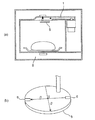
- the object to be heated used for the energy saving evaluation is an object to be heated 226 as shown in FIG. 8, and uses 1 L of water placed in a container having a large bottom area according to IEC regulations. In this case, it is determined that the object to be heated 226 is disposed at the center of the mounting table 208. Since energy saving is evaluated based on heating efficiency, in order to improve energy saving, heating efficiency must be improved as much as possible.
- an opening is used as the microwave radiating portion as in the structure of the second embodiment, a structure in which microwaves are directly irradiated to the object to be heated from the opening is advantageous.
- the microwave is diffused into the heating chamber without directly irradiating the object to be heated, the number of reflections in the heating chamber increases, and the wall loss in the heating chamber 202 and the mounting table are absorbed. This is because the ratio increases and the amount of microwave absorbed by the heated object is considered to decrease. Therefore, it is desirable to arrange the openings 204a to 207b directly under the object to be heated 226 as much as possible. In the configuration of the second embodiment, since most of the openings 204a to 207b are located directly under the object to be heated 226, it can be said that it is extremely advantageous for energy saving.
- the openings 204a and 204b and the openings 207a and 207b at both ends in the transmission direction are formed to be a little smaller or the width of the waveguide 203 is widened to shorten the aforementioned in-tube wavelength ⁇ g, and the transmission direction. If the openings 204a and 204b and the openings 207a and 207b at the both ends of the lens are configured to be closer to the inner side, a more efficient heating configuration that can further save energy is obtained. When such a change is made, the influence on the heating distribution is a concern.
- the width of the mounting table 208 in the width direction (left and right direction) is also narrow. do it.
- the mounting table 208 is described as a radiation region, and the region is slightly narrower than the left and right wall surfaces 214 and 211 of the heating chamber 202.
- the present invention is not limited to such a configuration. Instead, as shown in FIG. 2B of the first embodiment, a configuration in which the left and right end portions of the mounting table (107) coincide with the left and right wall surfaces (111, 112) can be selected.
- the mounting table 208 is a radiation region, as described above, there is an effect that the design for securing the distribution performance of five Chinese beakers is facilitated.
- FIG. 9 is a diagram for explaining the configuration of the main part of the microwave oven that is the microwave heating apparatus according to the third embodiment of the present invention, and schematically shows the microwave generator, the waveguide, the heating chamber, and the like.
- 9A is a cross-sectional view of the heating chamber viewed from above
- FIG. 9B is a cross-sectional view of the heating chamber viewed from the front.
- the microwave oven which is the microwave heating apparatus of the following third embodiment, the difference from the above-described first and second embodiments will be mainly described.
- components having the same functions as those of the first embodiment and the second embodiment described above are denoted by the same reference numerals, and description thereof is omitted.
- the configuration of the third embodiment is different from the configuration of the second embodiment in that six openings are provided and the configuration of the openings is different.
- the configuration in which the mounting table on which the object to be heated is placed is detachable is different from the configuration of the second embodiment.
- the openings 301a, 301b, 302a, 302b, 303a, and 303b are arranged in the width direction of the waveguide 203 (in FIG. 9A). Two are arranged side by side in the vertical direction), and three are arranged on both sides of the tube axis 216 which is the central axis of the waveguide 203.
- the three openings 301 a, 302 a, 303 a and the three openings 301 b, 302 b, 303 b are symmetrical with respect to the tube axis 216 on both sides of the tube axis 216 of the waveguide 203. It is arranged.
- the center of the opening 301a and the center of the opening 301b are provided at the same position. It is arranged to be a distance.
- the center of the opening 302a and the center of the opening 302b, and the center of the opening 303a and the center of the opening 303b are the same position in the transmission direction of the waveguide 203, and are arranged at the same distance from the tube axis 216. Has been.
- the openings 301a, 301b closest to the end 217 of the waveguide 203 and the openings 303a, 303b closest to the magnetron 201 are formed with the respective openings 301a, 301b, 303a, 303b.
- the long holes (slits) that do not cross each other at a right angle, and the crossing long holes have an acute angle in the transmission direction. That is, each of the openings 301a, 301b, 303a, and 303b has a crushed X-shape with a short length in the width direction of the waveguide.
- Each of the openings 301a, 301b, 303a, and 303b is disposed on the outer side in the width direction of the waveguide 203 (the front-rear direction of the heating chamber 202, that is, the vertical direction in FIG. 9A).
- the openings 301a, 301b, 303a, and 303b are configured as described above, the opening 301a, 301b, 303a, and 303b are microscopically diffused in the front-rear direction of the heating chamber 202. A wave is emitted.
- the openings 302a and 302b are arranged at the center between the openings 301a and 301b and the openings 303a and 303b.
- the openings 301a and 301b and the openings 303a and 303b are located on the antinodes of the standing waves in the tube. Since the openings 302a and 302b in the center are located at the antinodes of the standing waves in the tube, the amount of microwave radiation can be increased.
- the mounting table 304 is not fixed to the wall surface of the heating chamber 202 but is detachable from the heating chamber 202. For this reason, for example, when the mounting table 304 becomes dirty, it can be removed from the heating chamber 202 and easily washed.
- electrical components such as a motor for mechanically rotating the rotating antenna are located at the bottom of the heating chamber. Has been placed. For this reason, it is desirable that the bottom of the heating chamber does not contain water or steam that may lead to electrical shorts, and it is necessary to fix the gap between the bottom of the heating chamber and the mounting table with a putty or packing. there were.
- the mounting table 304 is configured to be detachable. It is good. For this reason, when the microwave heating apparatus having the configuration of the third embodiment is used, as shown in FIG. 9B, the mounting table 304 is placed on the bottom space 209 at the level difference of the bottom surface 210 of the heating chamber 202. It is being used. Incidentally, in the configuration of the third embodiment, since the mounting table 304 is detachable, the mounting table 304 may be placed at a position shifted from a normal position.
- FIG. 10 is a diagram illustrating an example when the mounting table 304 is placed shifted to the left.
- the shape of the left and right wall surfaces of the heating chamber 202 is not symmetrical. Further, depending on how the mounting table 304 is placed, there is a possibility that it is not placed symmetrically with respect to the heating chamber 202. Therefore, in the configuration of the third embodiment, attention is paid to the bottom space 209 as a radiation region for discussing symmetry.
- the center positions of the openings 301a and 301b and the center positions of the openings 303a and 303b are separated by approximately the in-tube wavelength ⁇ g.
- the center positions of 301a and 301b are at a distance of ⁇ g / 4 from the end 217 of the waveguide 203.
- the bottom space 209 is configured such that the lower side (opening side) is narrow and the upper side (mounting table side) is wide.
- an end 301a which is the upper left side above the bottom space 209 has an opening 301a close to the end side in the transmission direction of the waveguide 203.
- a distance of ⁇ g / 2 is formed in the transmission direction of the waveguide 203 from the center position of 301b.
- the end 306 on the right end side above the bottom space 209 is formed so as to have a distance of ⁇ g / 2 in the transmission direction of the waveguide 203 from the center position of the openings 303a and 303b.
- the bottom space 209 formed as described above gradually expands from the opening side on the lower side, and finally the length from the left end 305 to the right end 306 is the waveguide length.
- the length 203 (2 ⁇ g) is twice the guide wavelength in the transmission direction 203.
- a region from the left end 305 to the right end 306 in the bottom space 209 forms a radiation region.
- the left and right end portions 305 and 306 of the bottom space 209 in the transmission direction of the waveguide 203, and the center 307 This is a configuration in which an equal amount of microwaves is always radiated from the openings 301a, 301b, 303a, and 303b provided at positions just in the middle of (see FIG.
- microwaves can be radiated uniformly over the entire radiation region from the left end 305 to the right end 306 of the bottom space 209, and driving An object to be heated can be heated uniformly without using a mechanism.
- the wall surface of the heating chamber 202 is uneven as in the microwave oven of the third embodiment, even if the distance of the radiation region is determined by the distance between the wall surfaces of the heating chamber 202, the distance itself depends on the position to be measured. Will change.
- the mounting table 304 is detachable and has a degree of freedom in the mounting position as in the configuration of the third embodiment, or when the mounting table 304 having an asymmetric shape is used (not shown), radiation is performed. Even if the length of the region is determined by the mounting table 304, it may not be clearly determined. Therefore, in the above-described third embodiment, the range of the radiation region can be reliably determined by setting the radiation space from the left end 305 to the right end 306 of the bottom space 209, It becomes easy to discuss the distance to the aperture position for the radiation region.
- the microwave oven according to Embodiment 3 includes a heating chamber 202 that stores an object to be heated, a magnetron 201 that generates microwaves, a waveguide 203 that transmits microwaves, and a waveguide 203.
- the heating chamber 202 has six openings 301a, 301b, 302a, 302b, 303a, and 303b that radiate microwaves.
- the heating chamber 202 has a bottom space 209 as a radiation region having a length approximately twice the guide wavelength ( ⁇ g) in the transmission direction of the waveguide 203.
- the openings 301a and 301b and the openings 303a and 303b at both ends in the transmission direction are formed at positions separated from each other by substantially the in-tube wavelength in the transmission direction of the waveguide 203, and a center line 307 extending in the front-rear direction of the bottom space 209. Are arranged symmetrically.
- the openings 301a and 301b and the openings 303a and 303b at both ends separated by the guide wavelength are located at the center line 307 of the bottom space 209 having a length approximately twice the guide wavelength in the transmission direction of the waveguide 203. They are arranged symmetrically.
- the openings 301a and 301b and the openings 303a and 303b at both ends in the transmission direction are provided at intermediate positions from the center 307 in the transmission direction of the bottom space 209 to the end portions 305 and 306 at the left and right ends. . Further, since the openings 301a and 301b and the openings 303a and 303b at both ends in the transmission direction of the waveguide 203 are separated by the in-tube wavelength, the positional relationship is always in the same phase, and the inside of the waveguide 203 enters the heating chamber 202. It is a configuration that can always emit the same amount of microwaves.
- the same amount of microwaves is always obtained from the openings 301a and 301b and the openings 303a and 303b located just in the middle from the center 307 of the bottom space 209 to both ends 305 and 306. Therefore, the microwave can be radiated uniformly to the entire space in the left-right direction (transmission direction) of the bottom space 209, and the object to be heated can be radiated without using a driving mechanism. It can be heated uniformly.
- the microwave heating apparatus exemplified as the microwave oven in Embodiment 3
- the mounting table 304 is defined.
- the bottom space 209 is formed.
- the same amount of microwaves can always be radiated from the openings 301a and 301b and the openings 303a and 303b located just in the middle from the center 307 in the left and right direction (transmission direction) of the bottom space 209 to both ends 305 and 306. it can.
- the microwave can be uniformly radiated from the end to the end of the bottom space 209, and the object to be heated can be removed without using a driving mechanism. It can be heated uniformly.
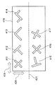
- FIG. 11 is a diagram illustrating an opening shape that is a microwave radiating unit in the microwave heating apparatus according to the fourth embodiment of the present invention, for example, a microwave oven.
- the difference from the configurations of the first to third embodiments is the opening shape, and the other configurations apply the configurations of the first to third embodiments. .
- an opening shape constituted by at least two or more long holes (slits) that radiate circularly polarized waves as the microwave radiation part will be described.
- the openings 411 to 417 shown in FIG. 11 it is composed of two or more long holes.
- the long side of at least one long hole is inclined with respect to the microwave transmission direction (arrow 418). Therefore, a shape in which the long holes do not intersect like the opening 415 and the opening 416 or a shape constituted by three long holes like the opening 414 may be used.
- the following three points can be given as conditions for the best shape of the opening as the microwave radiating portion that radiates circularly polarized waves constituted by two long holes (slits).
- the first point is that the length of the long side of each long hole is about 1 ⁇ 4 or more of the guide wavelength ⁇ g in the waveguide 419.
- the second point is that the two long holes are orthogonal to each other, and the long side of each long hole is inclined (for example, 45 °) with respect to the transmission direction 418.
- the third point is that the electric field distribution is not axisymmetric with respect to a straight line that is parallel to the transmission direction 418 of the waveguide 419 and that passes through the center of the opening that is the microwave radiation portion.
- the electric field is symmetrically distributed with the tube axis 421 (see FIG. 11), which is the center line in the width direction 420 of the waveguide 419, as the symmetry axis.
- the best condition is that the opening shape is not axially symmetric with respect to the tube axis 421, that is, the opening center is not on the tube axis 421.
- the long holes are orthogonal to each other, but as shown in FIG. 9 of the third embodiment, the long holes are inclined without being orthogonal to each other to form an X-shape. It is also possible to use an X-shape that is crushed so as to be long in the horizontal direction (transmission direction). Even when the squeezed X-shaped opening (microwave radiation part) is used, the circularly polarized wave can be radiated, although it is deformed from a perfect circle and becomes an ellipse. The center of the opening can be brought closer to the end side in the width direction of the waveguide without reducing the hole. As a result, the microwave can be further expanded mainly in the width direction of the waveguide (direction orthogonal to the transmission direction).
- an L-shaped shape like the opening 413 and a T-shaped shape like the opening 415 may be used. it can.
- the present invention can also be applied when the long holes (slits) are separated from each other as in the above-mentioned Patent Document 2.
- the two long holes (slits) do not have to be orthogonal to each other, and may be formed to be inclined if, for example, about 30 degrees.
- the long holes (slits) that constitute the openings that are the microwave radiation portions are not limited to rectangles.
- circularly polarized aperture it can be inferred that it is only necessary to combine two elongated apertures that are longer in one direction and shorter in the direction orthogonal to the one direction.
- a microwave heating apparatus includes a heating chamber (102, 202) for storing an object to be heated, a microwave generation unit (103, 201) for generating a microwave, A waveguide (104, 203) for transmitting microwaves, and a plurality of microwave radiation units for radiating microwaves from the waveguide into the heating chamber,
- the heating chamber has a radiation region in which microwaves from the plurality of microwave radiation parts are radiated, and the radiation region has a length approximately twice the guide wavelength in the transmission direction of the waveguide, At least two of the microwave radiating portions are provided at positions separated from each other by a wavelength substantially in the tube in the transmission direction of the waveguide, and are arranged symmetrically with respect to a center line orthogonal to the transmission direction in the radiation region.
- the two microwave radiating portions separated by the in-tube wavelength are symmetrically arranged in the radiation region having a length approximately twice the in-tube wavelength.
- the wave radiating portion is located exactly in the middle of the region from the center to both ends of the radiation region. Further, since the two microwave radiating portions are separated by the in-tube wavelength, the positional relationship is always in the same phase, and the same amount of microwaves can always be radiated from the inside of the waveguide toward the heating chamber.
- the microwave heating apparatus always radiates the same amount of microwaves from the two microwave radiating portions provided at just the middle positions in the region from the center to both ends of the radiating region. Therefore, it is possible to uniformly radiate microwaves from the entire end of the radiating region to the end, and it is possible to uniformly heat the object to be heated without using a driving mechanism.
- the microwave heating apparatus of the present invention can uniformly irradiate an object to be heated with microwaves, it can be effectively used for a heating apparatus that performs heating processing or sterilization of food to be heated. it can.
Landscapes
- Physics & Mathematics (AREA)
- Electromagnetism (AREA)
- Constitution Of High-Frequency Heating (AREA)
- Electric Ovens (AREA)
- Waveguide Aerials (AREA)
Abstract
Priority Applications (4)
| Application Number | Priority Date | Filing Date | Title |
|---|---|---|---|
| EP13791362.0A EP2852251A4 (fr) | 2012-05-15 | 2013-04-26 | Dispositif de chauffage à micro-ondes |
| US14/400,493 US20150136758A1 (en) | 2012-05-15 | 2013-04-26 | Microwave heating device |
| JP2014515485A JPWO2013171990A1 (ja) | 2012-05-15 | 2013-04-26 | マイクロ波加熱装置 |
| CN201380025395.4A CN104488352B (zh) | 2012-05-15 | 2013-04-26 | 微波加热装置 |
Applications Claiming Priority (2)
| Application Number | Priority Date | Filing Date | Title |
|---|---|---|---|
| JP2012-111224 | 2012-05-15 | ||
| JP2012111224 | 2012-05-15 |
Publications (1)
| Publication Number | Publication Date |
|---|---|
| WO2013171990A1 true WO2013171990A1 (fr) | 2013-11-21 |
Family
ID=49583420
Family Applications (1)
| Application Number | Title | Priority Date | Filing Date |
|---|---|---|---|
| PCT/JP2013/002864 Ceased WO2013171990A1 (fr) | 2012-05-15 | 2013-04-26 | Dispositif de chauffage à micro-ondes |
Country Status (5)
| Country | Link |
|---|---|
| US (1) | US20150136758A1 (fr) |
| EP (1) | EP2852251A4 (fr) |
| JP (1) | JPWO2013171990A1 (fr) |
| CN (1) | CN104488352B (fr) |
| WO (1) | WO2013171990A1 (fr) |
Cited By (2)
| Publication number | Priority date | Publication date | Assignee | Title |
|---|---|---|---|---|
| CN109780585A (zh) * | 2019-03-01 | 2019-05-21 | 北京石油化工学院 | 一种微波辐射控制系统 |
| JP2023003444A (ja) * | 2021-06-24 | 2023-01-17 | 三菱電機株式会社 | 加熱調理器 |
Families Citing this family (20)
| Publication number | Priority date | Publication date | Assignee | Title |
|---|---|---|---|---|
| US10560986B2 (en) | 2013-08-20 | 2020-02-11 | Whirlpool Corporation | Method for detecting the status of popcorn in a microwave |
| EP3087805B1 (fr) | 2013-12-23 | 2018-05-30 | Whirlpool Corporation | Circuit interrupteur pour générateur radiofréquence |
| DE102014112522A1 (de) * | 2014-09-01 | 2016-03-03 | Miele & Cie. Kg | Gargerät |
| WO2016144872A1 (fr) | 2015-03-06 | 2016-09-15 | Whirlpool Corporation | Procédé d'étalonnage d'amplificateur haute puissance pour un système de mesure de puissance radioélectrique |
| JP7027891B2 (ja) | 2015-06-03 | 2022-03-02 | ワールプール コーポレイション | 電磁調理のための方法および装置 |
| WO2017071166A1 (fr) * | 2015-10-28 | 2017-05-04 | 广东美的厨房电器制造有限公司 | Four à micro-ondes, guide d'ondes rectangulaire et procédé de détermination correspondant |
| CN105390785B (zh) * | 2015-10-28 | 2018-11-27 | 广东美的厨房电器制造有限公司 | 一种微波炉、矩形波导及其确定方法 |
| US11483905B2 (en) | 2016-01-08 | 2022-10-25 | Whirlpool Corporation | Method and apparatus for determining heating strategies |
| WO2017119910A1 (fr) | 2016-01-08 | 2017-07-13 | Whirlpool Corporation | Séparateur isolé pour four à micro-ondes à plusieurs cavités |
| CN108605391B (zh) | 2016-01-28 | 2020-11-17 | 松下电器产业株式会社 | 用于传送射频电磁能量以烹饪食品的方法和设备 |
| JP6775027B2 (ja) | 2016-02-15 | 2020-10-28 | パナソニック株式会社 | 食品を調理するために高周波電磁エネルギーを伝達する方法および装置 |
| KR101781477B1 (ko) * | 2016-09-19 | 2017-10-23 | 유한회사 에스피앤파트너스 | 전자 레인지 및 그의 방사 모듈 |
| US10827569B2 (en) | 2017-09-01 | 2020-11-03 | Whirlpool Corporation | Crispness and browning in full flat microwave oven |
| US11039510B2 (en) | 2017-09-27 | 2021-06-15 | Whirlpool Corporation | Method and device for electromagnetic cooking using asynchronous sensing strategy for resonant modes real-time tracking |
| US11412584B2 (en) | 2017-12-08 | 2022-08-09 | Alkar-Rapidpak, Inc. | Ovens with metallic belts and microwave launch box assemblies for processing food products |
| US10772165B2 (en) | 2018-03-02 | 2020-09-08 | Whirlpool Corporation | System and method for zone cooking according to spectromodal theory in an electromagnetic cooking device |
| US11404758B2 (en) | 2018-05-04 | 2022-08-02 | Whirlpool Corporation | In line e-probe waveguide transition |
| US10912160B2 (en) | 2018-07-19 | 2021-02-02 | Whirlpool Corporation | Cooking appliance |
| CN115720618A (zh) * | 2020-08-25 | 2023-02-28 | 松下知识产权经营株式会社 | 高频加热烹调器 |
| US12563647B2 (en) | 2021-04-26 | 2026-02-24 | Alkar-Rapidpak, Inc. | Food processing machines with microwave heating systems and microwave suppression systems |
Citations (9)
| Publication number | Priority date | Publication date | Assignee | Title |
|---|---|---|---|---|
| JPS5628198U (fr) * | 1980-07-15 | 1981-03-16 | ||
| US4301347A (en) | 1980-08-14 | 1981-11-17 | General Electric Company | Feed system for microwave oven |
| JPS5755089A (en) * | 1980-09-18 | 1982-04-01 | Tokyo Shibaura Electric Co | High frequency heater |
| JPS57148797U (fr) * | 1981-03-13 | 1982-09-18 | ||
| JPH02279923A (ja) * | 1989-04-20 | 1990-11-15 | Toshiba Corp | ヒータ付高周波加熱調理装置 |
| JP2003173867A (ja) * | 2001-12-04 | 2003-06-20 | Samsung Electronics Co Ltd | 電子レンジ |
| JP3510523B2 (ja) | 1998-04-06 | 2004-03-29 | エルジー電子株式会社 | 電子レンジおよび導波管システム |
| JP2005235772A (ja) | 2004-02-19 | 2005-09-02 | Lg Electronics Inc | 電子レンジ |
| JP2010139217A (ja) * | 2008-12-15 | 2010-06-24 | Yamamoto Vinita Co Ltd | 加熱方法および加熱装置 |
Family Cites Families (6)
| Publication number | Priority date | Publication date | Assignee | Title |
|---|---|---|---|---|
| JPS57124378A (en) * | 1981-01-26 | 1982-08-03 | Canon Inc | Fixing device |
| JPS59198697A (ja) * | 1983-04-25 | 1984-11-10 | 松下電器産業株式会社 | 高周波加熱装置 |
| KR850000580B1 (ko) * | 1983-12-31 | 1985-04-29 | 주식회사 금성사 | 마이크로파 오븐의 균일가열 장치 |
| CH684373A5 (de) * | 1992-10-29 | 1994-08-31 | Inwave Ag | Vorrichtung zur Einkopplung von Mikrowellen. |
| US7323772B2 (en) * | 2002-08-28 | 2008-01-29 | Micron Technology, Inc. | Ball grid array structures and tape-based method of manufacturing same |
| JP5102486B2 (ja) * | 2006-12-28 | 2012-12-19 | パナソニック株式会社 | マイクロ波加熱装置 |
-
2013
- 2013-04-26 WO PCT/JP2013/002864 patent/WO2013171990A1/fr not_active Ceased
- 2013-04-26 CN CN201380025395.4A patent/CN104488352B/zh active Active
- 2013-04-26 JP JP2014515485A patent/JPWO2013171990A1/ja active Pending
- 2013-04-26 US US14/400,493 patent/US20150136758A1/en not_active Abandoned
- 2013-04-26 EP EP13791362.0A patent/EP2852251A4/fr not_active Withdrawn
Patent Citations (9)
| Publication number | Priority date | Publication date | Assignee | Title |
|---|---|---|---|---|
| JPS5628198U (fr) * | 1980-07-15 | 1981-03-16 | ||
| US4301347A (en) | 1980-08-14 | 1981-11-17 | General Electric Company | Feed system for microwave oven |
| JPS5755089A (en) * | 1980-09-18 | 1982-04-01 | Tokyo Shibaura Electric Co | High frequency heater |
| JPS57148797U (fr) * | 1981-03-13 | 1982-09-18 | ||
| JPH02279923A (ja) * | 1989-04-20 | 1990-11-15 | Toshiba Corp | ヒータ付高周波加熱調理装置 |
| JP3510523B2 (ja) | 1998-04-06 | 2004-03-29 | エルジー電子株式会社 | 電子レンジおよび導波管システム |
| JP2003173867A (ja) * | 2001-12-04 | 2003-06-20 | Samsung Electronics Co Ltd | 電子レンジ |
| JP2005235772A (ja) | 2004-02-19 | 2005-09-02 | Lg Electronics Inc | 電子レンジ |
| JP2010139217A (ja) * | 2008-12-15 | 2010-06-24 | Yamamoto Vinita Co Ltd | 加熱方法および加熱装置 |
Non-Patent Citations (1)
| Title |
|---|
| See also references of EP2852251A4 |
Cited By (3)
| Publication number | Priority date | Publication date | Assignee | Title |
|---|---|---|---|---|
| CN109780585A (zh) * | 2019-03-01 | 2019-05-21 | 北京石油化工学院 | 一种微波辐射控制系统 |
| CN109780585B (zh) * | 2019-03-01 | 2024-03-01 | 北京石油化工学院 | 一种微波分布控制系统 |
| JP2023003444A (ja) * | 2021-06-24 | 2023-01-17 | 三菱電機株式会社 | 加熱調理器 |
Also Published As
| Publication number | Publication date |
|---|---|
| CN104488352B (zh) | 2016-10-12 |
| JPWO2013171990A1 (ja) | 2016-01-12 |
| EP2852251A1 (fr) | 2015-03-25 |
| US20150136758A1 (en) | 2015-05-21 |
| CN104488352A (zh) | 2015-04-01 |
| EP2852251A4 (fr) | 2015-06-03 |
Similar Documents
| Publication | Publication Date | Title |
|---|---|---|
| WO2013171990A1 (fr) | Dispositif de chauffage à micro-ondes | |
| US10045403B2 (en) | Microwave heating device | |
| CN103718644B (zh) | 微波加热装置 | |
| CN1171506C (zh) | 用于甚高频装置中的波导管和采用该波导管的微波炉 | |
| CN103916998B (zh) | 微波加热装置 | |
| JP5895247B2 (ja) | マイクロ波加熱装置 | |
| CN103582199B (zh) | 微波加热装置 | |
| JP6273598B2 (ja) | マイクロ波加熱装置 | |
| CN103687122B (zh) | 微波加热装置 | |
| JP6179814B2 (ja) | マイクロ波加熱装置 | |
| JP2014229532A (ja) | マイクロ波加熱装置 | |
| JP2015015225A (ja) | マイクロ波加熱装置 | |
| CN103889086B (zh) | 微波加热装置 | |
| JP2013191349A (ja) | マイクロ波加熱装置 | |
| JP2014089942A (ja) | マイクロ波加熱装置 | |
| JP2013125670A (ja) | マイクロ波加熱装置 | |
| JP2007141538A (ja) | マイクロ波加熱装置 | |
| JP6424332B2 (ja) | マイクロ波加熱装置 | |
| JP2015162321A (ja) | 高周波加熱装置 | |
| JP2014053231A (ja) | マイクロ波加熱装置 | |
| JP2014150018A (ja) | マイクロ波加熱装置 | |
| JP2013109987A (ja) | マイクロ波加熱装置 | |
| JP2014160632A (ja) | マイクロ波加熱装置 | |
| JP2013171648A (ja) | マイクロ波加熱装置 | |
| JP2014116175A (ja) | マイクロ波加熱装置 |
Legal Events
| Date | Code | Title | Description |
|---|---|---|---|
| 121 | Ep: the epo has been informed by wipo that ep was designated in this application |
Ref document number: 13791362 Country of ref document: EP Kind code of ref document: A1 |
|
| WWE | Wipo information: entry into national phase |
Ref document number: 2013791362 Country of ref document: EP |
|
| ENP | Entry into the national phase |
Ref document number: 2014515485 Country of ref document: JP Kind code of ref document: A |
|
| WWE | Wipo information: entry into national phase |
Ref document number: 14400493 Country of ref document: US |
|
| NENP | Non-entry into the national phase |
Ref country code: DE |