WO2013172003A1 - Puce de détection d'organismes et dispositif de détection d'organismes équipé de celle-ci - Google Patents
Puce de détection d'organismes et dispositif de détection d'organismes équipé de celle-ci Download PDFInfo
- Publication number
- WO2013172003A1 WO2013172003A1 PCT/JP2013/002989 JP2013002989W WO2013172003A1 WO 2013172003 A1 WO2013172003 A1 WO 2013172003A1 JP 2013002989 W JP2013002989 W JP 2013002989W WO 2013172003 A1 WO2013172003 A1 WO 2013172003A1
- Authority
- WO
- WIPO (PCT)
- Prior art keywords
- chamber
- detection chip
- measurement
- flow path
- living body
- Prior art date
- Legal status (The legal status is an assumption and is not a legal conclusion. Google has not performed a legal analysis and makes no representation as to the accuracy of the status listed.)
- Ceased
Links
Images












Classifications
-
- G—PHYSICS
- G01—MEASURING; TESTING
- G01N—INVESTIGATING OR ANALYSING MATERIALS BY DETERMINING THEIR CHEMICAL OR PHYSICAL PROPERTIES
- G01N35/00—Automatic analysis not limited to methods or materials provided for in any single one of groups G01N1/00 - G01N33/00; Handling materials therefor
- G01N35/00029—Automatic analysis not limited to methods or materials provided for in any single one of groups G01N1/00 - G01N33/00; Handling materials therefor provided with flat sample substrates, e.g. slides
-
- C—CHEMISTRY; METALLURGY
- C12—BIOCHEMISTRY; BEER; SPIRITS; WINE; VINEGAR; MICROBIOLOGY; ENZYMOLOGY; MUTATION OR GENETIC ENGINEERING
- C12Q—MEASURING OR TESTING PROCESSES INVOLVING ENZYMES, NUCLEIC ACIDS OR MICROORGANISMS; COMPOSITIONS OR TEST PAPERS THEREFOR; PROCESSES OF PREPARING SUCH COMPOSITIONS; CONDITION-RESPONSIVE CONTROL IN MICROBIOLOGICAL OR ENZYMOLOGICAL PROCESSES
- C12Q1/00—Measuring or testing processes involving enzymes, nucleic acids or microorganisms; Compositions therefor; Processes of preparing such compositions
- C12Q1/02—Measuring or testing processes involving enzymes, nucleic acids or microorganisms; Compositions therefor; Processes of preparing such compositions involving viable microorganisms
- C12Q1/04—Determining presence or kind of microorganism; Use of selective media for testing antibiotics or bacteriocides; Compositions containing a chemical indicator therefor
-
- B—PERFORMING OPERATIONS; TRANSPORTING
- B01—PHYSICAL OR CHEMICAL PROCESSES OR APPARATUS IN GENERAL
- B01L—CHEMICAL OR PHYSICAL LABORATORY APPARATUS FOR GENERAL USE
- B01L3/00—Containers or dishes for laboratory use, e.g. laboratory glassware; Droppers
- B01L3/50—Containers for the purpose of retaining a material to be analysed, e.g. test tubes
- B01L3/502—Containers for the purpose of retaining a material to be analysed, e.g. test tubes with fluid transport, e.g. in multi-compartment structures
- B01L3/5027—Containers for the purpose of retaining a material to be analysed, e.g. test tubes with fluid transport, e.g. in multi-compartment structures by integrated microfluidic structures, i.e. dimensions of channels and chambers are such that surface tension forces are important, e.g. lab-on-a-chip
- B01L3/502738—Containers for the purpose of retaining a material to be analysed, e.g. test tubes with fluid transport, e.g. in multi-compartment structures by integrated microfluidic structures, i.e. dimensions of channels and chambers are such that surface tension forces are important, e.g. lab-on-a-chip characterised by integrated valves
-
- B—PERFORMING OPERATIONS; TRANSPORTING
- B01—PHYSICAL OR CHEMICAL PROCESSES OR APPARATUS IN GENERAL
- B01L—CHEMICAL OR PHYSICAL LABORATORY APPARATUS FOR GENERAL USE
- B01L3/00—Containers or dishes for laboratory use, e.g. laboratory glassware; Droppers
- B01L3/52—Containers specially adapted for storing or dispensing a reagent
- B01L3/527—Containers specially adapted for storing or dispensing a reagent for a plurality of reagents
-
- B—PERFORMING OPERATIONS; TRANSPORTING
- B01—PHYSICAL OR CHEMICAL PROCESSES OR APPARATUS IN GENERAL
- B01L—CHEMICAL OR PHYSICAL LABORATORY APPARATUS FOR GENERAL USE
- B01L2200/00—Solutions for specific problems relating to chemical or physical laboratory apparatus
- B01L2200/04—Exchange or ejection of cartridges, containers or reservoirs
-
- B—PERFORMING OPERATIONS; TRANSPORTING
- B01—PHYSICAL OR CHEMICAL PROCESSES OR APPARATUS IN GENERAL
- B01L—CHEMICAL OR PHYSICAL LABORATORY APPARATUS FOR GENERAL USE
- B01L2200/00—Solutions for specific problems relating to chemical or physical laboratory apparatus
- B01L2200/06—Fluid handling related problems
- B01L2200/0605—Metering of fluids
-
- B—PERFORMING OPERATIONS; TRANSPORTING
- B01—PHYSICAL OR CHEMICAL PROCESSES OR APPARATUS IN GENERAL
- B01L—CHEMICAL OR PHYSICAL LABORATORY APPARATUS FOR GENERAL USE
- B01L2200/00—Solutions for specific problems relating to chemical or physical laboratory apparatus
- B01L2200/16—Reagents, handling or storing thereof
-
- B—PERFORMING OPERATIONS; TRANSPORTING
- B01—PHYSICAL OR CHEMICAL PROCESSES OR APPARATUS IN GENERAL
- B01L—CHEMICAL OR PHYSICAL LABORATORY APPARATUS FOR GENERAL USE
- B01L2300/00—Additional constructional details
- B01L2300/04—Closures and closing means
- B01L2300/041—Connecting closures to device or container
- B01L2300/042—Caps; Plugs
-
- B—PERFORMING OPERATIONS; TRANSPORTING
- B01—PHYSICAL OR CHEMICAL PROCESSES OR APPARATUS IN GENERAL
- B01L—CHEMICAL OR PHYSICAL LABORATORY APPARATUS FOR GENERAL USE
- B01L2300/00—Additional constructional details
- B01L2300/04—Closures and closing means
- B01L2300/041—Connecting closures to device or container
- B01L2300/043—Hinged closures
-
- B—PERFORMING OPERATIONS; TRANSPORTING
- B01—PHYSICAL OR CHEMICAL PROCESSES OR APPARATUS IN GENERAL
- B01L—CHEMICAL OR PHYSICAL LABORATORY APPARATUS FOR GENERAL USE
- B01L2300/00—Additional constructional details
- B01L2300/08—Geometry, shape and general structure
- B01L2300/0809—Geometry, shape and general structure rectangular shaped
- B01L2300/0816—Cards, e.g. flat sample carriers usually with flow in two horizontal directions
-
- B—PERFORMING OPERATIONS; TRANSPORTING
- B01—PHYSICAL OR CHEMICAL PROCESSES OR APPARATUS IN GENERAL
- B01L—CHEMICAL OR PHYSICAL LABORATORY APPARATUS FOR GENERAL USE
- B01L2300/00—Additional constructional details
- B01L2300/08—Geometry, shape and general structure
- B01L2300/0861—Configuration of multiple channels and/or chambers in a single devices
- B01L2300/0864—Configuration of multiple channels and/or chambers in a single devices comprising only one inlet and multiple receiving wells, e.g. for separation, splitting
-
- B—PERFORMING OPERATIONS; TRANSPORTING
- B01—PHYSICAL OR CHEMICAL PROCESSES OR APPARATUS IN GENERAL
- B01L—CHEMICAL OR PHYSICAL LABORATORY APPARATUS FOR GENERAL USE
- B01L2300/00—Additional constructional details
- B01L2300/08—Geometry, shape and general structure
- B01L2300/0861—Configuration of multiple channels and/or chambers in a single devices
- B01L2300/0867—Multiple inlets and one sample wells, e.g. mixing, dilution
-
- B—PERFORMING OPERATIONS; TRANSPORTING
- B01—PHYSICAL OR CHEMICAL PROCESSES OR APPARATUS IN GENERAL
- B01L—CHEMICAL OR PHYSICAL LABORATORY APPARATUS FOR GENERAL USE
- B01L2400/00—Moving or stopping fluids
- B01L2400/04—Moving fluids with specific forces or mechanical means
- B01L2400/0403—Moving fluids with specific forces or mechanical means specific forces
- B01L2400/0409—Moving fluids with specific forces or mechanical means specific forces centrifugal forces
-
- B—PERFORMING OPERATIONS; TRANSPORTING
- B01—PHYSICAL OR CHEMICAL PROCESSES OR APPARATUS IN GENERAL
- B01L—CHEMICAL OR PHYSICAL LABORATORY APPARATUS FOR GENERAL USE
- B01L2400/00—Moving or stopping fluids
- B01L2400/06—Valves, specific forms thereof
- B01L2400/0633—Valves, specific forms thereof with moving parts
-
- B—PERFORMING OPERATIONS; TRANSPORTING
- B01—PHYSICAL OR CHEMICAL PROCESSES OR APPARATUS IN GENERAL
- B01L—CHEMICAL OR PHYSICAL LABORATORY APPARATUS FOR GENERAL USE
- B01L2400/00—Moving or stopping fluids
- B01L2400/06—Valves, specific forms thereof
- B01L2400/0677—Valves, specific forms thereof phase change valves; Meltable, freezing, dissolvable plugs; Destructible barriers
-
- G—PHYSICS
- G01—MEASURING; TESTING
- G01N—INVESTIGATING OR ANALYSING MATERIALS BY DETERMINING THEIR CHEMICAL OR PHYSICAL PROPERTIES
- G01N35/00—Automatic analysis not limited to methods or materials provided for in any single one of groups G01N1/00 - G01N33/00; Handling materials therefor
- G01N35/00029—Automatic analysis not limited to methods or materials provided for in any single one of groups G01N1/00 - G01N33/00; Handling materials therefor provided with flat sample substrates, e.g. slides
- G01N2035/00099—Characterised by type of test elements
- G01N2035/00158—Elements containing microarrays, i.e. "biochip"
-
- G—PHYSICS
- G01—MEASURING; TESTING
- G01N—INVESTIGATING OR ANALYSING MATERIALS BY DETERMINING THEIR CHEMICAL OR PHYSICAL PROPERTIES
- G01N33/00—Investigating or analysing materials by specific methods not covered by groups G01N1/00 - G01N31/00
- G01N33/48—Biological material, e.g. blood, urine; Haemocytometers
- G01N33/483—Physical analysis of biological material
- G01N33/487—Physical analysis of biological material of liquid biological material
Definitions
- the present invention relates to a living body detection chip used for detecting bacteria and viruses that cause various infectious diseases, for example, and a living body detection apparatus including the same.
- a conventional biological detection chip includes a main body case having a diluent chamber and a measurement chamber connected to the diluent chamber via a first flow path, and a note provided in a portion corresponding to the diluent chamber of the main body case.
- An inlet and a sealing member for sealing the inlet were provided inside.
- the measurement chamber has a branch chamber section connected to the diluent chamber via the first flow path, and a plurality of individual measurement sections respectively connected to the branch chamber section via the second flow path. It was. And the individual reagent was provided in the separate measurement part (for example, patent document 1).
- an object of the present invention is to prevent a reduction in measurement accuracy due to contamination and to reduce costs.
- the living body detection chip includes a main body case, an injection port, a sealing member, a branch chamber, a plurality of individual measurement units, a reagent mounting port, and a cap.
- the main body case includes a diluent chamber and a measurement chamber connected to the diluent chamber via a first flow path.
- the inlet is provided in a portion corresponding to the diluent chamber in the main body case, and a specimen is injected.
- the sealing member seals the injection port.
- the branch chamber portion is connected to the diluent chamber through the first flow path in the measurement chamber.
- the plurality of individual measurement units are respectively connected to the branch chamber unit via the second flow path in the measurement chamber.
- the reagent mounting port is provided at a position communicating with the individual measurement unit on the outer surface of the main body case.
- the cap is mounted on the reagent mounting port, and an individual reagent is provided on the surface exposed to the individual measurement unit side.
- the individual reagent necessary for detection is provided on the surface exposed to the individual measurement unit side of the cap. And it is set as the structure which can mount
- the individual reagents are held in advance in a small cap that is easy to manage the environment such as cleanliness, the occurrence of contamination between the individual reagents can be prevented. Therefore, it is possible to eliminate the adverse effect on the measurement accuracy due to contamination of individual reagents and improve the measurement accuracy. Further, since the cap is smaller than the main body case, even when a plurality of caps are managed, they can be easily managed in a small space. Therefore, the cost can be reduced also from this point.
- measurement is performed by rotating the main body of the biological detection chip and applying a centrifugal force to the specimen held in the holding chamber, thereby sending the specimen to each quantitative chamber and measurement chamber.
- appropriate analysis is performed by keeping the amount of the specimen sent to each measurement chamber constant.
- the amount of the sample that flows into the dispensing chamber from the holding chamber via the first flow path is smaller than the volume of the dispensing chamber, and each quantitative chamber The amount is small enough to allow a fixed amount to flow into.
- each metering chamber only needs to be filled. Sample flows in. However, in the vicinity of the inlet of each quantitative chamber, there is a state in which a specimen that can flow to the adjacent quantitative chamber exists. In this state, a constant sample does not flow into each quantitative chamber, and the sample amount in the quantitative chamber becomes unstable.
- an object of the present invention is to perform an appropriate analysis by stabilizing the amount of a sample held in a quantitative chamber using a biodetection chip for biochemical analysis.
- a biological detection chip is a biological detection chip that is set in a biological detection device and performs measurement of a specimen while rotating, and includes a main body, a holding chamber, a dispensing chamber, and a plurality of quantitative determinations.
- a chamber and a plurality of measurement chambers are provided.
- the main body has an injection port into which a specimen for biochemical analysis is injected.
- the holding chamber holds the injected specimen in the main body.
- the dispensing chamber is connected to the holding chamber via the first flow path, and dispenses the specimen.
- the plurality of quantitative chambers are connected to the dispensing chamber, hold a predetermined amount of the dispensed specimen, and are arranged at positions away from the rotational center of the rotational motion as the distance from the first flow path increases.
- the plurality of measurement chambers are connected to the quantification chamber via the second flow path, and cause the specimen and a reagent for biochemical analysis to react.
- the rotation of the quantitative chamber disposed at a position away from the first flow path among the multiple quantitative chambers is more rotationally moved. It is arranged at a position away from the center of rotation. Therefore, in order from the side close to the first flow path, the quantitative chamber is filled with the specimen, whereby the specimen is successively supplied to the adjacent quantitative chambers arranged on the downstream side in the rotation direction.
- the living body detection chip according to the third invention includes a main body case, an injection port, a cap, and a sealing member.
- the main body case includes therein a dilution chamber and a measurement chamber connected to the dilution chamber via a flow path.
- the inlet is provided in a portion corresponding to the diluent chamber in the main body case.
- the cap seals the inlet from outside the main body case.
- the sealing member is provided on the diluent chamber side of the inlet, and has a sealing portion that seals the flow path and opens the flow path in a state where the inlet is sealed with a cap.
- the flow channel can be opened in a state where the sealing portion where the flow channel is sealed by the sealing member seals the injection port with the cap. Therefore, even if the user accidentally drops the living body detection chip before use, the flow path is physically sealed by the sealing portion, so that the diluent does not flow into the measurement chamber. can do. As a result, detection accuracy can be increased.
- a biological detection chip includes an inlet, a holding chamber, a plurality of flow paths, a plurality of measurement chambers, a temperature melting agent, and a reservoir.
- a specimen is injected into the inlet.
- the holding chamber holds the specimen injected from the inlet.
- the sample flowing from the holding chamber branches and flows through the plurality of flow paths.
- the plurality of measurement chambers cause the sample that has flowed in through the plurality of flow paths to react with the reagent held inside.
- the temperature melting agent is filled in the closing portions provided in the plurality of flow paths, and melts when the temperature becomes a predetermined temperature or higher.
- the pool part is provided in a direction intersecting with the flow path in the closing part.
- the temperature melting agent is provided in the direction intersecting the flow path even when a centrifugal force is applied to the living body detection chip. It will be in the state caught in the pool part. Therefore, it is possible to prevent the temperature melting agent from inadvertently flowing into the measurement chamber. As a result, the inflow timing of the sample flowing into each measurement chamber becomes substantially constant, and the test performed using the living body detection chip can be stabilized.
- the living body detection chip includes a main body, a holding chamber, a measurement chamber, and a marker.
- the main body has an injection port for injecting a specimen.
- the holding chamber is provided in the main body and holds the specimen injected from the injection port.
- the measurement chamber is connected to the holding chamber through a flow path in the main body, and the mixed liquid reagent is generated by reacting the sample flowing from the holding chamber with the built-in reagent.
- the marker measures the amount of fluorescence when the main body rotates, and is provided on the rotation trajectory of the measurement chamber in the main body.
- the optical unit of the biological detection device emits light from the mixed liquid reagent in the measurement chamber of the sample test chip to emit light. Measure the amount of fluorescence produced.
- the living body detection chip of the present invention includes a marker for measuring the amount of fluorescence on the rotation orbit of the measurement chamber.
- the amount of fluorescence emitted from the marker can be measured.
- the amount of fluorescence emitted from the marker more significantly reflects the influence of the temperature adjustment unit.
- the fluorescence amount emitted from the mixed liquid reagent can be corrected based on the change in the fluorescence amount emitted from the marker.
- the measurement accuracy of the fluorescence amount can be increased even in an environment where the living body detection apparatus is downsized and the optical unit is affected by the temperature adjusting unit. That is, the measurement accuracy of the specimen can be increased.
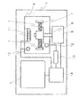
- FIG. 1 is a perspective view of a living body detection apparatus using a living body detection chip according to Embodiment 1 of the present invention.
- 1 is a configuration diagram of a living body detection apparatus according to Embodiment 1 of the present invention.
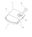
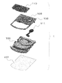
- 1 is a perspective view of a living body detection chip according to Embodiment 1 of the present invention.
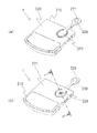
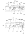
- (A) is a perspective view in the state without a cap of the individual measurement part of the living body detection chip concerning Embodiment 1 of the present invention.
- (B) is sectional drawing in the state without a cap of the separate measurement part of the biological detection chip which concerns on Embodiment 1 of this invention.
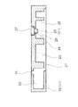
- (A) is a perspective view in the state with a cap of the individual measurement part of the living body detection chip concerning Embodiment 1 of the present invention.
- (B) is sectional drawing in the state with a cap of the separate measurement part of the biological detection chip which concerns on Embodiment 1 of this invention.
- the perspective view of the cap which concerns on Embodiment 1 of this invention.
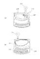
- the top view of the biological detection chip which concerns on Embodiment 2 of this invention The supplementary figure of the top view of the biological detection chip which concerns on Embodiment 2 of this invention.
- (A) is a perspective view with an inlet seal of the biological detection chip concerning Embodiment 3 of the present invention.
- (B) is a perspective view without the inlet seal of the biological detection chip concerning Embodiment 3 of the present invention.
- (A) is an internal block diagram of the biological detection chip
- B) is an internal block diagram of the biological detection chip
- FIG. 14B is a cross-sectional view taken along the line II-II showing a state after sealing by the sealing member of the living body detection chip of FIG.
- (A) is an enlarged view of the vicinity of the closing portion of the living body detection chip according to Embodiment 4 of the present invention.
- (B), (c), (d) is an enlarged view showing another embodiment of the present invention.
- (A), (b) is AA sectional drawing of FIG. The top view of the marker chamber and detection area which concern on Embodiment 5 of this invention.
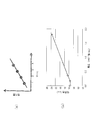
- (A) is explanatory drawing of the fluorescence amount of the marker which concerns on Embodiment 5 of this invention.
- (B) is a figure which shows the relationship between the density
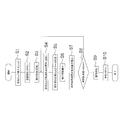
- the flowchart which shows the flow of a measurement of the biological detection apparatus which concerns on Embodiment 5 of this invention. Explanatory drawing of the change of the fluorescence amount which concerns on Embodiment 5 of this invention. Explanatory drawing of the relational expression of the fluorescence amount which concerns on Embodiment 5 of this invention.
- FIG. 1 is an example of a living body detection apparatus, and shows a living body detection apparatus that performs influenza virus detection and type discrimination as an example of biological information collected from a human body.
- the living body detection device of the present embodiment includes a living body detection chip 1 in which an influenza specimen is accommodated, an apparatus body 2, and an opening for inserting the living body detection chip 1 into the apparatus body 2.
- Part 3 a lid part 4 for closing the opening part 3, and a display part 5 provided on the surface on which the opening part 3 is formed and displaying a detection result.
- a space 6 communicating with the opening 3 is formed in the apparatus main body 2 as shown in FIG.
- a rotating tray 7 for fixing the living body detection chip 1 is disposed in the space 6.
- the rotation tray 7 is connected to a shaft connected to the rotation mechanism unit 8 at the center thereof, and is rotated by the rotation mechanism unit 8. Further, a temperature sensor 10 is disposed above the space 6.
- the temperature sensor 10 is provided to monitor the temperature in the space 6, and the heater 11 disposed in the space 6 is turned on / off based on the temperature detected by the temperature sensor 10, thereby The temperature in 6 can be adjusted to a predetermined temperature.
- An optical detection sensor 12 is disposed on the bottom surface of the rotating tray 7 facing the lower surface of the living body detection chip 1 in the space 6.
- the optical detection sensor 12 detects an influenza sample in the living body detection chip 1. Furthermore, a calculation unit 13 that calculates a value detected by the optical detection sensor 12 and a control unit 14 that controls the living body detection device are arranged inside the apparatus main body 2. In the present embodiment, in the present embodiment, a plurality of individual reagents that react with a plurality of types of viruses are accommodated in the living body detection chip 1 in order to detect the type of influenza specimen.
- the living body detection chip 1 includes a main body case 17 configured by superposing a substantially rectangular cover 15 and a substantially rectangular base 16.
- the cover 15 has an injection port 18 for injecting a specimen at one corner portion of a substantially square shape.
- the inlet 18 is sealed by a sealing member 19. Further, as shown in FIG. 4, a diluent chamber 20 that communicates with the injection port 18 is provided at a portion of the main body case 17 on the injection port 18 side. Diluent is stored in the diluent chamber 20 in advance. In the state of FIG. 3, a seal (not shown) is attached to the injection port 18 so that the diluent does not flow out of the injection port 18.
- a measurement chamber 22 connected to the diluent chamber 20 via the first flow path 21 is provided in the main body case 17 (more specifically, the base 16). Is provided.
- the measurement chamber 22 includes a branch chamber section 23 connected to the diluent chamber 20 via a first flow path 21 and a plurality of individual measurements connected to the branch chamber section 23 via a second flow path 24, respectively.
- Part 25 As shown in FIG. 6, the individual measurement unit 25 has a plurality of reagent mounting ports 26 on the surface of the main body case 17 where the injection port 18 is formed, that is, on the base 16 portion on the cover 15 side. Yes. Then, a cap 27 holding individual reagents of different types is attached to the plurality of reagent attachment ports 26 in a detachable state. Each individual measurement unit 25 has a common reagent 28 that reacts with a plurality of types of specimens on the bottom surface facing the reagent loading port 26 as shown in FIGS. 7 (a) and 7 (b). Yes.
- a plurality of reagent mounting ports 26 are formed on the upper surface side of the base 16 constituting the main body case 17, that is, on the cover 15 side where the injection port 18 is formed. Yes. Further, as shown in FIG. 7B, a film 16a is provided on the lower surface side of the base 16, that is, the surface facing the reagent mounting port 26.
- the film 16 a and the base 16 constitute an individual measurement unit 25.
- the individual measurement unit 25 has a rectangular shape arranged along the radial direction centering on the injection port 18.
- the individual measurement unit 25 is connected to the second flow path 24 on the film 16a side.
- the individual measurement unit 25 is connected to the branch chamber unit 23 via the second flow path 24. Further, the liquid common reagent 28 is dropped onto the film 16 a from the reagent mounting port 26 and dried to hold the common reagent 28 in the individual measurement unit 25.
- the common reagent 28 is an essential common reagent for detecting bacteria and viruses, and plays a role of amplifying the specimen present in the specimen diluent. Therefore, the individual reagent 29 that individually reacts with the bacteria and viruses that are the detection targets needs to be separately held in the individual measurement unit 25. Therefore, in the present embodiment, as shown in FIGS. 8A and 8B, the individual reagents 29 are held by a plurality of caps 27 mounted on the reagent mounting port 26.
- the cap 27 has a substantially cylindrical shape, and a circular recess 31 is formed on the inner surface of the individual measurement unit 25.
- the recess 31 fixes the individual reagent 29 by dropping the liquid individual reagent 29 inside and drying it.
- the concave portion 31 has a substantially bowl shape, and is dried and fixed in a state where the individual reagent 29 spreads uniformly on the inner peripheral surface of the concave portion 31 due to the surface tension of the liquid.
- the cap 27 to which the individual reagent 29 is fixed is prepared by fixing a different type of individual reagent 29 for each of the plurality of reagent mounting ports 26. It can be attached to the mouth 26. Thereby, for example, when there are individual reagents 29 corresponding to a plurality of types such as A type and B type as in influenza virus, different individual reagents 29 are used when detecting a specimen. Can be attached to the individual measuring unit 25 to check which individual reagent 29 the sample reacts in one detection.
- measurement can be carried out by fixing different types of individual reagents 29 to caps 27 attached to the individual measurement units 25 adjacent to each other.
- the type of influenza virus can be easily detected.
- the cap 27 is fixed to the circular reagent mounting opening 26 with an adhesive 35 as shown in FIG. Therefore, even when an external force such as a centrifugal force is applied, the cap 27 does not come off.
- the portion of the cap 27 to which the adhesive 35 is applied is outside the individual measurement unit 25 in a state where the cap 27 is mounted on the reagent mounting port 26. Thereby, the adhesive 35 does not reach the individual reagent 29 in the individual measuring unit 25. That is, the recess 31 is provided in order to prevent the adhesive 35 applied to the cap 27 from covering the surface of the individual reagent 29 and hindering its reaction.
- the concave portion 31 is formed so as to be surrounded by an annular bank.
- a sample collected from a human body causes a good reaction with the individual reagent 29 at about 60 ° C., for example. If the temperature is much lower than 60 ° C., it takes a long time to react, and if the temperature is much higher than 60 ° C., the specimen itself is destroyed and does not react. For this reason, it is necessary to allow the sample diluent to flow into the individual measurement unit 25 in a state where the inside of the individual measurement unit 25 is maintained at 60 ° C.
- a hot-melt sealing agent that fills the space in the second flow path 24 is provided.
- the hot-melt sealing agent one that melts at about 40 ° C. is used. Thereby, in the middle of heating the individual measurement unit 25 of the living body detection chip 1 until it reaches 60 ° C., the hot-melt sealing agent in the second channel 24 starts to melt, A space in which the specimen diluent moves is formed.
- pouring of the hot-melt sealing agent to the 2nd flow path 24 is the state before mounting
- the specimen diluent is introduced into the individual measurement unit 25 to which the individual reagent 29 is attached, and is subjected to an amplification reaction.
- the optical detection sensor 12 By detecting the amplification reaction by the optical detection sensor 12, it is possible to recognize which individual reagent 29 the sample is reacting with. Then, the result is displayed on the display unit 5.
- the individual reagent 29 necessary for detection is provided on the surface of the cap 27 exposed in the individual measurement unit 25. And the structure which can mount
- the main body case 17 is managed as a common part, and the cap 27 may be appropriately selected and mounted in accordance with the individual application such as a virus to be detected.
- costs such as production costs and management costs can be significantly reduced.
- the cap 27 is smaller than the main body case 17, even when managing a plurality of caps 27, the cap 27 can be easily managed in a small space. Therefore, the cost can be reduced also from this point.
- the living body detection chip 1 can be mounted with a cap 27 holding an individual reagent 29 in the reagent mounting port 26 of the individual measuring unit 25. For this reason, since the individual reagent 29 is held in advance by the small cap 27 that is easy to manage the environment such as cleanliness, contamination of the individual reagent 29 can be prevented. As a result, it is possible to eliminate the adverse effect on the measurement accuracy due to the contamination of the individual reagent 29 and improve the measurement accuracy.
- each individual reagent 29 can be applied and dried in the blocked space, and contamination occurring between the individual reagents 29 can be prevented.
- the common reagent 28 is disposed in each case of the main body case.
- the film 16a for sealing the individual measuring unit 25 is generally formed of a plastic film or the like, and is bonded to the main body case 17 using means such as heat welding. For this reason, when the heat resistance of the reagent is low, the reagent may be deactivated by heat.
- the common reagent 28 is attached from the reagent mounting port 26 to the film 16a after the film 16a is bonded to the main body case 17 by heat welding. Can be applied. Therefore, the inactivation of the common reagent 28 can be effectively prevented.
- FIG. 1 is an example of a living body detection apparatus, and shows a living body detection apparatus that detects an influenza sample.
- the living body detection chip 1 in which the influenza sample is injected is inserted into the living body detection apparatus shown in FIG.
- the living body detection chip 1 is set by being inserted into the apparatus body 2 from the opening 3 formed in the apparatus body 2 of the living body detection device.
- the device body 2 of the living body detection device is provided with a lid 4 for closing the opening 3 and a display 5 for displaying the detection result.
- the biological detection chip 1 is set inside the device main body 2 of the biological detection device, and the result of the biochemical analysis is displayed on the display unit 5. Further, as shown in FIG. 10, the biological detection chip 1 that performs biochemical analysis includes a chip body 106, a lower cover 107, an injection port 108, an upper cover 109, an attached cover 110, a sealing member 111, It has.
- the chip body 106 includes a holding chamber 112, a dispensing chamber 114, a metering chamber 115, a measuring chamber 117, and the like which will be described later (see FIG. 11 and the like).
- the lower cover 107 is attached to the lower surface of the chip body 106.
- the injection port 108 is attached to the upper surface of the chip body 106, and a specimen for biochemical analysis is injected.
- the upper cover 109 has an inlet 108 formed therein.
- the attached cover 110 is attached to the upper surface of the upper cover 109.
- the sealing member 111 seals the injection port 108.
- the configuration of the chip body 106 will be described in detail below. As shown in FIG. 11, the chip body 106 includes a holding chamber 112, a dispensing chamber 114, a plurality of metering chambers 115, and a plurality of measuring chambers 117.
- the holding chamber 112 holds the injected specimen.
- the dispensing chamber 114 is connected to the holding chamber 112 via the first flow path 113 and dispenses the specimen.
- the plurality of quantitative chambers 115 are connected to the dispensing chamber 114 and hold the dispensed specimen.
- the plurality of measurement chambers 117 are respectively connected to the quantification chamber 115 via the second flow path 116 to react the specimen and the reagent for biochemical analysis.
- the reagent used in this embodiment is applied in advance to the inside of the measurement chamber 117.
- an overflow chamber 118 is formed at a position farther from the first flow path 113 than the plurality of quantitative chambers 115.
- the overflow chamber 118 is provided on the downstream side of the plurality of quantitative chambers 115 in the rotation direction of the living body detection chip 1.
- the overflow chamber 118 stores and holds the specimen overflowing from the quantitative chamber 115.
- the quantification when the living body detection chip 1 is rotationally moved in a state set in the living body detection device, the quantification at a position away from the first flow path 113 among the plurality of quantification chambers 115.
- the chamber 115 is arranged at a position farther from the rotation center in the rotational movement than the quantitative chamber 115 located near the first flow path 113.
- the plurality of quantitative chambers 115 are arranged such that the distances (d1 to d4) from the rotation center of the chip body 106 are d1 ⁇ d2 ⁇ d3 ⁇ d4. It arrange
- the plurality of fixed-quantity chambers 115 are farther from the first flow path 113 than the rotation center of the chip body 106 (the center point of the arc A) and are radial with respect to the arc A. It arrange
- the shape of the dispensing chamber 114 is a substantially fan shape in a plan view, and the radial length of the first end close to the first flow path 113 at both side ends thereof.
- the length in the radial direction of the second end away from the first flow path 113 is shorter.
- the radial lengths of the first and second ends mean the fan-shaped radial length around the rotation center of the chip body 106.
- the sample is sequentially filled from the quantitative chamber 115 on the side closer to the first flow path 113, so that the sample is sequentially supplied to the quantitative chamber 115 disposed on the downstream side in the rotation direction.
- an overflow chamber 118 is provided on the most downstream side in the rotation direction of the plurality of quantitative chambers 115. For this reason, it is possible to prevent the backflow of the specimen from the overflow chamber 118 to each quantitative chamber 115 during the rotational movement. As a result, the amount of specimen held in the quantitative chamber 115 can be stabilized and appropriate analysis can be performed.
- the sample is supplied from the holding chamber 112 to the measurement chamber 117 via the dispensing chamber 114 and the quantitative chamber 115 by rotating the chip body 106 set in the living body detection apparatus.
- the rotation speed of the chip body 106 may be changed to stir the sample and the reagent.
- the sample in the overflow chamber 118 undulates along with the change in the rotation speed, and there is a possibility that it flows back to the quantitative chamber 115.
- the plurality of quantitative chambers 115 are arranged at positions away from the rotational center of the rotational movement of the chip body 106 as the distance from the first flow path 113 increases.
- the reverse flow of the sample can be prevented from occurring for the same reason as that in which the so-called lower wave hardly reaches the upper shore. it can.
- each quantitative chamber 115 can maintain a state in which a certain specimen flows. For this reason, it is possible to perform an appropriate analysis by stabilizing the amount of the sample held in the measurement chamber 117 to which the sample is supplied.
- the overflow chamber 118 is arranged such that the distance d5 from the rotation center of the chip body 106 is d4 ⁇ d5 with respect to the distance d4 of the adjacent quantitative chamber 115. Therefore, the specimen overflowing from the quantitative chamber 115 can be stably flowed into the overflow chamber 118. Furthermore, it is possible to prevent the specimen once flowing into the overflow chamber 118 from flowing into the quantitative chamber 115 arranged on the upstream side in the rotation direction. As a result, a predetermined amount of specimen can be stably held in the quantitative chamber 115, and appropriate analysis can be performed.
- the biological detection chip 1 that performs influenza virus detection and type discrimination will be described in detail below as an example of biological information of a sample collected from the nostril of a human body.
- the living body detection chip 1 includes a diluent chamber 216 and a measurement chamber 218 connected to the diluent chamber 216 via a flow path 217.
- a case 219 is provided.
- the main body case 219 has an inlet 220 at a portion corresponding to the diluent chamber 216.
- the injection port 220 is sealed by a sealing member 221 from the outside of the main body case 219.
- a seal is provided so that a measurement-inhibiting factor such as contamination does not flow into the diluent chamber 216 into the inlet 220 of the living body detection chip 1 before the specimen is injected.
- 222 is affixed. Thereby, the inlet 220 is sealed by the seal 222.
- the diluent chamber 216 encloses a diluent for diluting the specimen.
- a sealing member 224 is arranged inside the diluent chamber 216 as shown in FIGS.
- the sealing member 224 has through holes 227 formed at both ends in the longitudinal direction.
- a support column 226 that supports the sealing member 224 provided in the diluent chamber 216 while being movable in the axial direction is inserted into the through hole 227. Accordingly, the sealing member 224 can move downward in the drawing along the axial direction of the support column 226 in the diluent chamber 216.
- FIG. 16A shows a state before the inlet 220 by the sealing member 221 is sealed.
- the sealing member 224 is disposed in a state where the sealing portion 223 seals the opening 225 side in the flow path 217.
- the diluent chamber 216 is sealed by the cover 231.
- the injection port 220 is sealed with a seal 222.
- the specimen collected using a pipette or the like is injected into the diluent chamber 216 with the seal 222 removed and the injection port 220 opened.
- the specimen is mixed with the diluent and becomes a mixed liquid having a constant concentration by taking the specimen into and out of the diluent chamber 216 from the pipette via the inlet 220.
- the operator closes the injection port 220 using the sealing member 221.
- the sealing member 221 is formed with a protruding portion 28.
- the outer diameter of the protrusion 228 is larger than the inner diameter of the injection port 220.
- the material of the cover 231 in which the injection port 220 is formed is harder than the material of the sealing member 221 having the protruding portion 228.
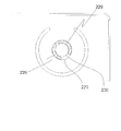
- the sealing member 221 is pushed into the injection port 220 while being elastically deformed by pushing the sealing member 221 into the injection port 220. In this state, the sealing member 221 is configured not to easily come off from the injection port 220. Further, as shown in FIG. 15, a pressure receiving portion 229 is provided along the outer peripheral edge at the end of the living body inlet 230 formed on the sealing member 224 on the inlet 220 side. Then, when the sealing member 221 is inserted into the injection port 220, the pressure receiving unit 229 contacts the protruding portion 228.
- the sealing member 224 disposed in the diluent chamber 216 has the protruding portion 228 of the sealing member 221 abuts on the pressure receiving portion 229, and the diluent from the inlet 220 side. It is pushed toward the inside of the chamber 216.
- the inner diameter of the through-hole 227 of the sealed sealing member 224 is smaller than the outer diameter of the support column 226 formed in the diluent chamber 216, and the material of the sealing member 224 is harder than the material of the support column 226. . Therefore, the sealing member 224 is configured not to easily come off from the support column 226 when the support column 226 is elastically deformed.
- the sealing member 224 is formed of a material harder than the cover 231 and the column 226. Therefore, as shown in FIGS. 15 and 16B, even when the pressure receiving portion 229 is pushed by the sealing member 221 and the sealing member 224 is press-fitted and fixed to the column 226, the sealing member 224 is not bent and the column is not bent. 226 is fixed. Therefore, the opening 225 side of the flow channel 217 is released from the sealing by the sealing portion 223 and is in an open state.
- the flow path 217 between the diluent chamber 216 and the measurement chamber 218 is secured in conjunction with the operation of sealing the inlet 220 by the sealing member 221.
- the mixed liquid in which the diluent and the sample are mixed flows from the diluent chamber 216 into the measurement chamber 218.
- the pressure receiving portion 229 of the sealing member 224 has a substantially annular shape including a notch portion in part along the outer peripheral edge of the living body inlet 230.
- the living body detection chip 1 into which the specimen has been injected is inserted from the opening 3 of the living body detection apparatus and set on the rotating tray 7. Then, when the operator inputs from the display unit 5 of the apparatus main body 2 to start the apparatus and starts detection, the living body detection chip 1 is rotated and centrifugal force is applied to the liquid mixture. Thereby, the liquid mixture quantified by the centrifugal force flows into the measurement chamber 218. Then, the specimen is detected by the optical detection sensor 12, and the detection result is displayed on the display unit 5.
- the sealing portion 223 that seals the flow path 217 is in a state of sealing the injection port 220 with the sealing member 221, along the axial direction of the support column 226. By moving downward in the figure, the flow path 217 is opened. Thereby, even when the user accidentally drops the living body detection chip 1 before use, the flow path 217 is physically sealed by the sealing portion 223, so that the diluted solution flows into the measurement chamber 218. None do. As a result, the detection accuracy can be improved by preventing the dilution liquid and the sample from being mixed until just before use.
- the living body detection chip 1 of the present embodiment includes an injection port 302, a holding chamber 303, a plurality of flow paths 304, a plurality of measurement chambers 305, and a temperature melting agent (for example, wax). 309.
- a specimen is injected into the injection port 302.
- the holding chamber 303 holds the sample injected from the injection port 302.
- the sample flowing in from the holding chamber 303 is branched and flows.
- the plurality of measurement chambers 305 react the reagent held inside and the sample.
- a temperature melting agent (for example, wax or the like) 309 is filled in the closing portions 306 provided in the plurality of flow paths 304.
- the closing portion 306 is provided with a pool portion 307 in a direction intersecting with the flow path 304.
- the shape of the reservoir portion 307 is a rectangle (an actual three-dimensional shape is a cylinder) as shown in the plan view of FIG.
- the shape of the pool portion 307 may be elliptical as shown in FIG.
- the shape may have a rounded corner with respect to the rectangle, or may be a hexagonal shape as shown in FIG. 19D.
- the reservoir 307 is commonly formed on a line other than the extended line of the flow path 304 along the direction intersecting the flow path 304.
- the reservoir 307 is formed so that the filled temperature melting agent 309 is caught.
- the retaining portion 306 is provided with the reservoir portion 307 in the direction intersecting with the flow path 304.
- the temperature melting agent 309 is in a state of being caught by the pool portion 307 provided in the direction intersecting the flow path 304. As a result, the temperature melting agent 309 does not inadvertently flow into the measurement chamber 305, so that the inflow timing of the specimen flowing into each measurement chamber 305 can be made almost constant. Therefore, the inspection using the living body detection chip 1 can be stabilized.
- a branch portion 308 is provided at the axial center portion of the flow path in the closing portion 306.
- the branch portion 308 is formed by a protrusion 308a that protrudes from the inner surface of the closing portion 306 toward the axial center of the flow path.
- FIG. 20 is an internal configuration diagram of the device body 2 of the living body detection device in a state where the living body detection chip 1 is inserted.
- the main body 2 of the living body detection apparatus mainly includes a rotation mechanism unit 405, a temperature adjustment unit 406, an optical unit 407, and a data correction unit 408.
- FIG. 21 shows an internal configuration diagram (planar schematic diagram) of the living body detection chip 1.
- the living body detection chip 1 includes a plurality of measurement chambers 409 that hold a sealed sample and generate a mixed liquid reagent by reacting a reagent held in advance with the sample. ing.
- the components constituting the apparatus main body 2 and the living body detection chip 1 of the living body detection device will be described in detail using FIGS. 20 and 21 in the same manner as described above.
- the rotation mechanism unit 405 includes a chip holding unit 410 that holds the inserted biological detection chip 1, and a motor 411 that is connected to the chip holding unit 410 by a shaft and rotates the biological detection chip 1.
- the temperature adjustment unit 406 includes a housing 412 that covers the living body detection chip 1, a heater 413 that heats the inside of the housing 412, and a temperature sensor 414 that measures the temperature inside the housing 412. The temperature adjustment unit 406 can keep the internal temperature of the housing 412 and the temperature of the living body detection chip 1 constant by performing energization control of the heater 413 disposed inside the housing 412.
- the optical unit 407 includes a light source 415, a condenser lens 416, an illumination filter 417, a dichroic mirror 418, an objective lens 419, a fluorescence filter 420, and a detection unit 421.
- Light from the light source 415 (wavelength 470 nm LED) is collected by the condenser lens 416 and passes through the illumination filter 417.
- the illumination filter 417 is a band-pass filter that transmits 430 to 490 nm. Due to its transmission characteristics, light having the illumination wavelength of the fluorescent label is transmitted, but light having the fluorescence wavelength is cut. The light that has passed through the illumination filter 417 is reflected by the dichroic mirror 418, collected by the objective lens 419, and illuminates the mixed reagent stored in the measurement chamber 409 inside the biological detection chip 1.
- the fluorescence emitted from the mixed reagent is collected by the objective lens 419 and passes through the dichroic mirror 418 and the fluorescence filter 420.
- the dichroic mirror 418 reflects 430 to 490 nm and transmits 510 to 560 nm
- the illumination wavelength is reflected and the fluorescence wavelength is transmitted.
- the fluorescence filter 420 is a band-pass filter that transmits 510 to 560 nm. Due to its transmission characteristics, the illumination wavelength is cut and the fluorescence wavelength is transmitted. Then, the fluorescence amount of the fluorescence transmitted through the dichroic mirror 418 and the fluorescence filter 420 is measured by the detection unit 421.
- the data correction unit 408 includes an amplifier circuit 422, an analog data processing unit 423, and a digital data processing unit 424.
- the amplifier circuit 422 amplifies the signal output from the detector 421.
- the analog data processing unit 423 converts the signal amplified in the amplifier circuit 422 into a digital value.
- the digital data processing unit 424 performs processing such as collection and analysis on the digital value converted by the analog data processing unit 423.
- the main body of the living body detection chip 1 is made of ABS resin, and has a substantially rectangular shape with curved two sides as shown in FIG. Further, as shown in FIG. 21, the living body detection chip 1 has a through hole 425 in the central portion of the main body.
- the chip holding part 410 is inserted into the through hole 425 and the living body detection chip 1 is fixed inside the apparatus body 2.
- a groove and a reservoir are formed on one side of the living body detection chip 1 (not shown).
- the measurement chamber 409 (ch1 to ch6) and the marker chamber 426 (Mark1 to Mark4) are arranged concentrically as shown in FIG.
- the measurement chamber 409 and the marker chamber 426 are arranged at equal intervals.
- the marker chamber 426 has a marker at the bottom, and the optical unit 7 is used for measuring the amount of fluorescence.
- the measurement chamber 409 is 3 mm ⁇ 4 mm ⁇ (depth) 2 mm
- the marker chamber 426 is 1 mm ⁇ 4 mm ⁇ (depth) 1 mm.
- the flow of the specimen will be described using the living body detection chip 1.
- the specimen is spotted from the injection port 427 and temporarily stored in the injection chamber 428.
- the measurement chamber 409 is connected to the injection chamber 428 via a plurality of flow paths.
- the living body detection chip 1 is rotated using the rotation mechanism unit 405
- the specimen is sent to the measurement chamber 409 using a centrifugal force generated by the rotation.
- a reagent necessary for the reaction is sealed in advance, and a mixed liquid reagent is generated by mixing the specimen and the reagent using centrifugal force.
- a film 429 is formed on the upper surfaces of the measurement chamber 409 and the marker chamber 426 as shown in FIG. 22A, and a chamber region is formed therein.
- the film 429 is made of acrylic resin (PMMA) and has a thickness of 0.3 mm, and can be welded using a laser.
- the marker chamber 426 has a depth of the measurement chamber 409. It is formed so as to be about a half with respect to.
- the optical imaging position can be made to coincide with the substantially central portion of the measurement chamber 409.
- the optical imaging position is the measurement object, so that it can be detected so as to be located near the center of the liquid mixture reagent. As a result, the amount of fluorescence increases and efficient detection becomes possible.
- a specific example of a method for forming the marker chamber 426 for the living body detection chip 1 will be described below.
- the living body detection chip 1 is formed in a shape in which a portion corresponding to the marker chamber 426 is extracted, and then a fluorescent polymer particle diluted solution is spotted on the marker chamber 426.
- the marker chamber 426 is filled with the fluorescent polymer particle diluent.
- the fluorescent polymer particle diluted solution is naturally dried at room temperature. At this time, it is desirable that the humidity be as low as 40% or less.
- a film 429 is formed by laser welding. After forming the film 429, the amount of fluorescence of the dried marker is checked. This check is performed by measuring the amount of fluorescence using the optical unit 407 of the apparatus main body 2 of the living body detection apparatus, and confirms whether the amount of fluorescence is within the specification.
- the measured fluorescence information is converted into a barcode and attached to the living body detection chip 1.
- FIG. 22A the means for realizing the configuration shown in the drawing by extracting the portions corresponding to the measurement chamber 409 and the marker chamber 426 from the living body detection chip 1 has been described.
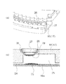
- a configuration as shown in FIG. 22B is also conceivable. That is, a through hole is provided in a portion corresponding to the measurement chamber 409 and the marker chamber 426 in the living body detection chip 1. And the film 429 is affixed on the upper surface of the biological detection chip
- a reagent for reacting the specimen is spotted on the upper surface of the measurement chamber unit 430, and then the reagent is dried and fixed on the upper surface of the measurement chamber unit 430. Further, fluorescent polymer particles are applied to the upper surface of the marker chamber unit 431. Then, the measurement chamber unit 430 and the marker chamber unit 431 are pasted from the back surface of the living body detection chip 1 using an adhesive.
- the depth of the marker chamber 426 is about one half of the depth of the measurement chamber 409 as in the configuration shown in FIG. Configured as follows.
- a specific example of a method of forming the marker chamber 426 for the living body detection chip 1 will be described below.
- the living body detection chip 1 is formed in a shape in which a through-hole as shown in FIG. 22B is formed, and then fluorescent polymer particles are applied to the upper surface of the marker chamber unit 431.
- Application of the fluorescent polymer particles is performed by coating. Specifically, a fluorescent polymer particle dilution liquid in which the fluorescent polymer particles are suspended in a colloidal form is generated, and the generated dilution liquid is applied using an air spray device dedicated to application. As other methods, a static electricity application spray, a dipping method, or the like may be used.
- the fluorescent polymer particle diluted solution is attached to the upper surface of the marker chamber unit 431 by the above method, it is dried and fixed.
- the fluorescence amount of the marker can be adjusted by changing the concentration of the fluorescent polymer particle diluent or repeating the steps of applying and drying the fluorescent polymer particle diluent.
- the shape of the marker chamber 426 in plan view is a substantially long hole shape as shown in FIG.
- the length on the circumferential direction side of the biological detection chip 1 that performs the rotational motion is the same length as the diameter of the detection area.
- the length in the radial direction of the living body detection chip 1 that performs the rotational motion is longer than the diameter of the detection area.
- the length of the marker chamber 426 in the radial direction is set longer than the length of the detection area. Therefore, even when an error occurs when the living body detection chip 1 is inserted, the fluorescence amount using the marker can be reliably measured.
- the length of the marker chamber 426 in the radial direction may be set to 4 mm and the length in the circumferential direction (minor axis) may be set to 1 mm.
- the bottom surface of the marker chamber 426 in FIGS. 22A and 22B, the bottom surface is formed horizontally, but the center portion of the bottom surface is formed deeper than the end portion. Also good.
- this method is used. This is particularly effective because the marker to be spotted can be easily concentrated on the central portion.
- the marker in the marker chamber 426 uses four types of markers (Mark 1 to Mark 4) arranged concentrically. For example, as shown in FIG. The amount of fluorescence of these markers is adjusted so that the amount of fluorescence has a directly proportional characteristic.
- This adjustment is adjusted by the concentration of the fluorescent polymer diluent that is spotted on the marker chamber 26. More specifically, as shown in FIG. 24 (b), since the concentration of the fluorescent polymer diluent and the amount of fluorescence of the marker in a predetermined amount are directly proportional to each other, this relationship is used for each marker. On the other hand, fluorescent polymer diluents having different concentrations are spotted.
- a measurement flow in the apparatus main body 2 of the living body detection apparatus of the present embodiment will be described with reference to FIG.
- a specimen such as blood is spotted on the living body detection chip 1
- the living body detection chip 1 is set in the opening 3 of the apparatus body 2 of the living body detection apparatus, and a touch panel type on the front surface of the body body 2 of the living body detection apparatus.
- Measurement start operation is performed by the display unit 5.
- an insertion check of the living body detection chip 1 is performed (S1).
- a barcode is provided on the curved side surface of the living body detection chip 1 having a thickness of 6 mm. For this reason, the worker reads the barcode and confirms that the living body detection chip is inserted. Also, the bar code reads the type of dry reagent applied to the living body detection chip 1, the value indicating the fluorescence amount before shipment of the marker, and the like.
- temperature adjustment is started (S2).
- the inside of the housing 412 that covers the living body detection chip 1 is heated by the heater 413, and the heater 413 inside the housing 412 is controlled based on the detection result of the temperature sensor 414. Thereby, the internal temperature of the housing 412 can be kept constant (60 ° C.).
- the sample is filled in the measurement chamber 409 (S3).
- the living body detection chip 1 is rotated by the rotation mechanism unit 405 (the rotation speed is 2500 rpm), and the specimen is moved to the measurement chamber 409 by centrifugal force. Then, the reagent spotted dry in the measurement chamber 409 in advance and the filled specimen are stirred by the centrifugal force generated by rotating the living body detection chip 1 to generate a mixed liquid reagent (S4).
- the living body detection chip 1 is rotated by the rotation mechanism unit 405 (rotation speed 240 rpm), and the optical unit 407 includes the mixed liquid reagent filled in the measurement chamber 409 (ch1 to 6) and the marker (Mark1 to Mark1) of the marker chamber 426.
- the amount of fluorescence of 4) is detected (scanned) (S5).
- the data correction unit 408 calculates correction coefficients ⁇ and ⁇ based on the fluorescence amount of the markers (Marks 1 to 4) (S6).
- the fluorescence amount of the mixed liquid reagent filled in the measurement chambers (ch1 to ch6) is corrected (S7).
- the optical unit 407 is detected every minute, and the total time is 40 minutes or more (S8).
- the fluorescence amount of the mixed liquid reagent filled in the measurement chamber 409 (ch1 to 6) exceeds a predetermined threshold value, “positive” is displayed on the touch panel display 5 as a positive determination.
- the predetermined threshold value is not exceeded, “negative” is displayed on the touch panel display unit 5 as a negative determination to inform the user (S9).
- FIG. 26 As shown in the change diagram of the fluorescence amount in FIG. 26, the optical unit 407 has the fluorescence for the mixed liquid reagent in the measurement chamber 409 (ch1 to 6) and the marker in the marker chamber 426 (Mark1 to Mark4). Measure the amount.
- S1 + 1 to S6 + n and Sm1 + 1 to Sm4 + n are fluorescence amounts measured in the measurement chamber 409 and the marker chamber 426, respectively, at times t1 to tn.
- the fluorescence amount of the mixed liquid reagent in the measurement chamber 409 (ch1 to 6) and the marker in the marker chamber 426 (Mark1 to Mark4) decreases with time.
- this property is used to correct the fluorescence amount in the mixed liquid reagent in the measurement chamber 409 (ch1 to ch6).
- S is the amount of fluorescence (Sm1 to Sm4)
- M is the marker (1 to 4).
- SM is the corrected fluorescence amount.
- the living body detection chip according to the present invention can effectively prevent the occurrence of contamination and improve the measurement accuracy, and can greatly reduce the costs such as production cost and management cost.
Landscapes
- Chemical & Material Sciences (AREA)
- Health & Medical Sciences (AREA)
- Life Sciences & Earth Sciences (AREA)
- Analytical Chemistry (AREA)
- General Health & Medical Sciences (AREA)
- Organic Chemistry (AREA)
- Clinical Laboratory Science (AREA)
- Chemical Kinetics & Catalysis (AREA)
- Physics & Mathematics (AREA)
- Biochemistry (AREA)
- Immunology (AREA)
- Wood Science & Technology (AREA)
- Proteomics, Peptides & Aminoacids (AREA)
- Engineering & Computer Science (AREA)
- Zoology (AREA)
- Medicinal Chemistry (AREA)
- General Physics & Mathematics (AREA)
- Dispersion Chemistry (AREA)
- Pathology (AREA)
- Hematology (AREA)
- Biotechnology (AREA)
- Molecular Biology (AREA)
- Microbiology (AREA)
- Biophysics (AREA)
- Toxicology (AREA)
- Bioinformatics & Cheminformatics (AREA)
- General Engineering & Computer Science (AREA)
- Genetics & Genomics (AREA)
- Apparatus Associated With Microorganisms And Enzymes (AREA)
- Automatic Analysis And Handling Materials Therefor (AREA)
Abstract
La présente invention concerne une puce de détection d'organismes équipée d'un boîtier de corps principal (17) comprenant une chambre à diluants (20) et une chambre de mesure (22) reliée à la chambre à diluants (20) par un premier circuit d'écoulement (21) ; un orifice de remplissage (18) situé dans une partie correspondant à la chambre à diluants (20) du boîtier du corps principal (17) ; et un élément de fermeture d'orifice (19) assurant la fermeture de l'orifice de remplissage (18). La chambre de mesure (22) comprend une partie correspondant à une chambre de dérivation (23) reliée à la chambre à diluants (20) par l'intermédiaire du premier circuit d'écoulement (21) et une pluralité de parties de mesure individuelles (25) respectivement reliées à la partie de type chambre de dérivation (23) par l'intermédiaire de seconds circuits d'écoulement (24). Dans chaque partie de mesure individuelle (25), un orifice de liaison de réactif (26) est présent. Un bouchon (27) est monté sur ledit orifice de liaison de réactif (26). Un unique réactif (29) est placé sur la surface mise à nu du côté de la partie de mesure individuelle (25) du bouchon (27).
Priority Applications (1)
| Application Number | Priority Date | Filing Date | Title |
|---|---|---|---|
| US14/501,848 US10023897B2 (en) | 2012-05-16 | 2014-09-30 | Biosensor chip, and biosensor device equipped with same |
Applications Claiming Priority (10)
| Application Number | Priority Date | Filing Date | Title |
|---|---|---|---|
| JP2012-112167 | 2012-05-16 | ||
| JP2012112167A JP2013238505A (ja) | 2012-05-16 | 2012-05-16 | 生体検出チップ |
| JP2012-112168 | 2012-05-16 | ||
| JP2012112168A JP2013238506A (ja) | 2012-05-16 | 2012-05-16 | 生体検出チップ |
| JP2012242427A JP2014092422A (ja) | 2012-11-02 | 2012-11-02 | 検体検査チップ |
| JP2012-242427 | 2012-11-02 | ||
| JP2012242425A JP6001418B2 (ja) | 2012-11-02 | 2012-11-02 | 生体化学分析用の処理チップ |
| JP2012-242425 | 2012-11-02 | ||
| JP2012242426A JP2014092421A (ja) | 2012-11-02 | 2012-11-02 | 検体検査チップ、及び、それを用いる生体化学分析装置 |
| JP2012-242426 | 2012-11-02 |
Related Child Applications (1)
| Application Number | Title | Priority Date | Filing Date |
|---|---|---|---|
| US14/501,848 Continuation US10023897B2 (en) | 2012-05-16 | 2014-09-30 | Biosensor chip, and biosensor device equipped with same |
Publications (1)
| Publication Number | Publication Date |
|---|---|
| WO2013172003A1 true WO2013172003A1 (fr) | 2013-11-21 |
Family
ID=49583432
Family Applications (1)
| Application Number | Title | Priority Date | Filing Date |
|---|---|---|---|
| PCT/JP2013/002989 Ceased WO2013172003A1 (fr) | 2012-05-16 | 2013-05-09 | Puce de détection d'organismes et dispositif de détection d'organismes équipé de celle-ci |
Country Status (2)
| Country | Link |
|---|---|
| US (1) | US10023897B2 (fr) |
| WO (1) | WO2013172003A1 (fr) |
Cited By (10)
| Publication number | Priority date | Publication date | Assignee | Title |
|---|---|---|---|---|
| JP2016118530A (ja) * | 2014-09-29 | 2016-06-30 | ツェー アー カズィゾ アーゲーC A Casyso Ag | 血液検査システムおよび方法 |
| US9897618B2 (en) | 2014-09-29 | 2018-02-20 | C A Casyso Gmbh | Blood testing system |
| JP2018522241A (ja) * | 2015-07-17 | 2018-08-09 | スタット−ダイアグノスティカ アンド イノベーション, エス. エル. | アッセイを実行するための流体システム |
| US10288630B2 (en) | 2014-09-29 | 2019-05-14 | C A Casyso Gmbh | Blood testing system and method |
| US10473674B2 (en) | 2016-08-31 | 2019-11-12 | C A Casyso Gmbh | Controlled blood delivery to mixing chamber of a blood testing cartridge |
| US10539579B2 (en) | 2014-09-29 | 2020-01-21 | C A Casyso Gmbh | Blood testing system and method |
| CN111321058A (zh) * | 2020-03-06 | 2020-06-23 | 成都博奥晶芯生物科技有限公司 | 一种微流体芯片光学定位码盘、装置及方法 |
| US10816559B2 (en) | 2014-09-29 | 2020-10-27 | Ca Casyso Ag | Blood testing system and method |
| US10843185B2 (en) | 2017-07-12 | 2020-11-24 | Ca Casyso Gmbh | Autoplatelet cartridge device |
| US11768211B2 (en) | 2008-12-23 | 2023-09-26 | C A Casyso Gmbh | Cartridge device for a measuring system for measuring viscoelastic characteristics of a sample liquid, a corresponding measuring system, and a corresponding method |
Families Citing this family (6)
| Publication number | Priority date | Publication date | Assignee | Title |
|---|---|---|---|---|
| US9795968B2 (en) * | 2014-04-21 | 2017-10-24 | Lawrence Livermore National Security, LLCq | Multi-chamber nucleic acid amplification and detection device |
| ES2822989T3 (es) | 2015-04-07 | 2021-05-05 | Cell Id Pte Ltd | Calentador de corriente continua |
| FI128087B (en) | 2017-06-30 | 2019-09-13 | Teknologian Tutkimuskeskus Vtt Oy | A microfluidic chip and a method for the manufacture of a microfluidic chip |
| US11975321B2 (en) | 2018-03-27 | 2024-05-07 | Lawrence Livermore National Security, Llc | Multi-channel optical detection system and method for multi-chamber assays |
| WO2020100720A1 (fr) * | 2018-11-12 | 2020-05-22 | 合同会社みらか中央研究所 | Dispositif de passage d'écoulement permettant l'examen d'un composant biogène et système d'examen de composant biogène |
| CN112756018B (zh) * | 2019-10-21 | 2025-01-28 | 广州万孚生物技术股份有限公司 | 微流控芯片及体外检测系统 |
Citations (4)
| Publication number | Priority date | Publication date | Assignee | Title |
|---|---|---|---|---|
| JP2006308366A (ja) * | 2005-04-27 | 2006-11-09 | Hitachi High-Technologies Corp | 化学分析装置及び化学分析カートリッジ |
| JP2007500850A (ja) * | 2003-05-29 | 2007-01-18 | バイエル・ヘルスケア・エルエルシー | マイクロ流体装置のパッケージング |
| JP2010025854A (ja) * | 2008-07-23 | 2010-02-04 | Konica Minolta Medical & Graphic Inc | マイクロ検査チップ |
| JP2011527753A (ja) * | 2008-07-10 | 2011-11-04 | サムスン エレクトロニクス カンパニー リミテッド | 試薬カートリッジ、該カートリッジを含む微細流動装置、該微細流動装置の製造方法、及び該微細流動装置を用いた生化学的試料分析方法 |
Family Cites Families (7)
| Publication number | Priority date | Publication date | Assignee | Title |
|---|---|---|---|---|
| JP4336834B2 (ja) | 2003-10-03 | 2009-09-30 | 独立行政法人物質・材料研究機構 | チップの使用方法及び検査チップ |
| JP2007024851A (ja) | 2005-07-16 | 2007-02-01 | Adobic:Kk | 検体分析チップおよび検体分析チップの使用方法 |
| JP2007333716A (ja) | 2006-06-19 | 2007-12-27 | Ogawa Hiroteru | 分離・秤量チップならびにその使用方法 |
| WO2008106719A1 (fr) | 2007-03-02 | 2008-09-12 | Corbett Research Pty Ltd | Appareil et procédé d'amplification d'acide nucléique |
| JP4911514B2 (ja) | 2007-05-14 | 2012-04-04 | 独立行政法人産業技術総合研究所 | マイクロチップ、液体分注方法 |
| KR101228308B1 (ko) * | 2007-05-23 | 2013-01-31 | 삼성전자주식회사 | 미세유동 칩을 이용한 디스크형 미세유동장치 및 생체물질마이크로어레이 칩을 이용한 디스크형 미세유동장치 |
| EP2329877A1 (fr) * | 2009-12-04 | 2011-06-08 | Roche Diagnostics GmbH | Elément micro-fluidique destiné à l'analyse d'un échantillon de liquide |
-
2013
- 2013-05-09 WO PCT/JP2013/002989 patent/WO2013172003A1/fr not_active Ceased
-
2014
- 2014-09-30 US US14/501,848 patent/US10023897B2/en active Active
Patent Citations (4)
| Publication number | Priority date | Publication date | Assignee | Title |
|---|---|---|---|---|
| JP2007500850A (ja) * | 2003-05-29 | 2007-01-18 | バイエル・ヘルスケア・エルエルシー | マイクロ流体装置のパッケージング |
| JP2006308366A (ja) * | 2005-04-27 | 2006-11-09 | Hitachi High-Technologies Corp | 化学分析装置及び化学分析カートリッジ |
| JP2011527753A (ja) * | 2008-07-10 | 2011-11-04 | サムスン エレクトロニクス カンパニー リミテッド | 試薬カートリッジ、該カートリッジを含む微細流動装置、該微細流動装置の製造方法、及び該微細流動装置を用いた生化学的試料分析方法 |
| JP2010025854A (ja) * | 2008-07-23 | 2010-02-04 | Konica Minolta Medical & Graphic Inc | マイクロ検査チップ |
Cited By (22)
| Publication number | Priority date | Publication date | Assignee | Title |
|---|---|---|---|---|
| US11768211B2 (en) | 2008-12-23 | 2023-09-26 | C A Casyso Gmbh | Cartridge device for a measuring system for measuring viscoelastic characteristics of a sample liquid, a corresponding measuring system, and a corresponding method |
| US12111326B2 (en) | 2008-12-23 | 2024-10-08 | C A Casyso Gmbh | Cartridge device for a measuring system for measuring viscoelastic characteristics of a sample liquid, a corresponding measuring system, and a corresponding method |
| US12105103B2 (en) | 2008-12-23 | 2024-10-01 | C A Casyso Gmbh | Cartridge device for a measuring system for measuring viscoelastic characteristics of a sample liquid, a corresponding measuring system, and a corresponding method |
| US11892459B2 (en) | 2008-12-23 | 2024-02-06 | C A Casyso Gmbh | Cartridge device for a measuring system for measuring viscoelastic characteristics of a sample liquid, a corresponding measuring system, and a corresponding method |
| US11879899B2 (en) | 2008-12-23 | 2024-01-23 | C A Casyso Gmbh | Cartridge device for a measuring system for measuring viscoelastic characteristics of a sample liquid, a corresponding measuring system, and a corresponding method |
| US11327069B2 (en) | 2014-09-29 | 2022-05-10 | Ca Casyso Gmbh | Blood testing system and method |
| US10288630B2 (en) | 2014-09-29 | 2019-05-14 | C A Casyso Gmbh | Blood testing system and method |
| US12578349B2 (en) | 2014-09-29 | 2026-03-17 | Ca Casyso Gmbh | Blood testing system and method |
| US10816559B2 (en) | 2014-09-29 | 2020-10-27 | Ca Casyso Ag | Blood testing system and method |
| US9897618B2 (en) | 2014-09-29 | 2018-02-20 | C A Casyso Gmbh | Blood testing system |
| JP2016118530A (ja) * | 2014-09-29 | 2016-06-30 | ツェー アー カズィゾ アーゲーC A Casyso Ag | 血液検査システムおよび方法 |
| US12031993B2 (en) | 2014-09-29 | 2024-07-09 | C A Casyso Gmbh | Blood testing system and method |
| US11719688B2 (en) | 2014-09-29 | 2023-08-08 | C A Casyso Gmbh | Blood testing system and method |
| US10175225B2 (en) | 2014-09-29 | 2019-01-08 | C A Casyso Ag | Blood testing system and method |
| US10539579B2 (en) | 2014-09-29 | 2020-01-21 | C A Casyso Gmbh | Blood testing system and method |
| JP2018522241A (ja) * | 2015-07-17 | 2018-08-09 | スタット−ダイアグノスティカ アンド イノベーション, エス. エル. | アッセイを実行するための流体システム |
| US12123870B2 (en) | 2015-07-17 | 2024-10-22 | Qiagen Gmbh | Fluidic system for performing assays |
| US10473674B2 (en) | 2016-08-31 | 2019-11-12 | C A Casyso Gmbh | Controlled blood delivery to mixing chamber of a blood testing cartridge |
| US12399187B2 (en) | 2016-08-31 | 2025-08-26 | Ca Casyso Gmbh | Controlled blood delivery to mixing chamber of a blood testing cartridge |
| US11691142B2 (en) | 2017-07-12 | 2023-07-04 | Ca Casyso Gmbh | Autoplatelet cartridge device |
| US10843185B2 (en) | 2017-07-12 | 2020-11-24 | Ca Casyso Gmbh | Autoplatelet cartridge device |
| CN111321058A (zh) * | 2020-03-06 | 2020-06-23 | 成都博奥晶芯生物科技有限公司 | 一种微流体芯片光学定位码盘、装置及方法 |
Also Published As
| Publication number | Publication date |
|---|---|
| US20150024477A1 (en) | 2015-01-22 |
| US10023897B2 (en) | 2018-07-17 |
Similar Documents
| Publication | Publication Date | Title |
|---|---|---|
| JP5341188B2 (ja) | アッセイ装置および方法 | |
| JP7005176B2 (ja) | 試料調製装置、試料調製システム、試料調製方法及び粒子分析装置 | |
| CN104838267B (zh) | 用于lal反应物质测试的向心微流体平台 | |
| JP3390001B2 (ja) | 多分析物試験ビヒクル | |
| CN102844425B (zh) | 样本分析系统及其使用方法 | |
| JP3187845B2 (ja) | 少なくとも一つの生理的液体試料における少なくとも一つのパラメータを測定するための方法及びシステム、ホルダ、並びに、試験装置 | |
| CN106471356B (zh) | 自动分析装置 | |
| JP6723409B2 (ja) | 分析チップ及び試料分析装置 | |
| KR20110091309A (ko) | 흡광도 측정 방법 및 장치 | |
| CN113295659A (zh) | 基于流监测的侧向流测定装置的质量/过程控制 | |
| JP6359535B2 (ja) | 血液沈降速度およびそれに関連する他のパラメータを決定する装置および方法 | |
| WO2006106962A1 (fr) | Dispositif de mesure de fluorescence, procédé de mesure de fluorescence, récipient pour mesure de fluorescence, et procédé de fabrication du récipient pour mesure de fluorescence | |
| US9517466B2 (en) | Measuring cassette and measuring device for the detection of target molecules in a liquid sample by measurement of fluorescence emission after excitation in an evanescent field | |
| EP4009055A1 (fr) | Cartouche de réactif | |
| US10502752B2 (en) | Reaction method including pipette height detection and correction | |
| JP6590795B2 (ja) | 試料分析装置 | |
| JP2021514051A (ja) | 分析装置 | |
| WO2017130369A1 (fr) | Procédé de détection, système de détection et dispositif de détection | |
| JP2026032045A (ja) | サンプルの特性を測定するための機器、システムおよび方法 | |
| JP6590796B2 (ja) | 試料分析装置 | |
| KR20100118340A (ko) | 측정용 광디스크, 광학적 측정 장치 및 이를 이용한 광학적 측정 방법 | |
| JP2006125981A (ja) | 分析装置 | |
| JP5426476B2 (ja) | 分析用具及びマイクロ分析システム | |
| KR20100075208A (ko) | 미세유동장치의 검출 챔버의 흡광도를 측정하는 장치 및 방법 | |
| JP2014092421A (ja) | 検体検査チップ、及び、それを用いる生体化学分析装置 |
Legal Events
| Date | Code | Title | Description |
|---|---|---|---|
| 121 | Ep: the epo has been informed by wipo that ep was designated in this application |
Ref document number: 13790061 Country of ref document: EP Kind code of ref document: A1 |
|
| NENP | Non-entry into the national phase |
Ref country code: DE |
|
| 122 | Ep: pct application non-entry in european phase |
Ref document number: 13790061 Country of ref document: EP Kind code of ref document: A1 |