WO2013172020A1 - Vibromètre photoacoustique - Google Patents
Vibromètre photoacoustique Download PDFInfo
- Publication number
- WO2013172020A1 WO2013172020A1 PCT/JP2013/003075 JP2013003075W WO2013172020A1 WO 2013172020 A1 WO2013172020 A1 WO 2013172020A1 JP 2013003075 W JP2013003075 W JP 2013003075W WO 2013172020 A1 WO2013172020 A1 WO 2013172020A1
- Authority
- WO
- WIPO (PCT)
- Prior art keywords
- photoacoustic
- wave
- image
- acoustic
- light
- Prior art date
- Legal status (The legal status is an assumption and is not a legal conclusion. Google has not performed a legal analysis and makes no representation as to the accuracy of the status listed.)
- Ceased
Links
Images


Classifications
-
- A—HUMAN NECESSITIES
- A61—MEDICAL OR VETERINARY SCIENCE; HYGIENE
- A61B—DIAGNOSIS; SURGERY; IDENTIFICATION
- A61B5/00—Measuring for diagnostic purposes; Identification of persons
- A61B5/0093—Detecting, measuring or recording by applying one single type of energy and measuring its conversion into another type of energy
- A61B5/0097—Detecting, measuring or recording by applying one single type of energy and measuring its conversion into another type of energy by applying acoustic waves and detecting light, i.e. acousto-optic measurements
-
- G—PHYSICS
- G01—MEASURING; TESTING
- G01S—RADIO DIRECTION-FINDING; RADIO NAVIGATION; DETERMINING DISTANCE OR VELOCITY BY USE OF RADIO WAVES; LOCATING OR PRESENCE-DETECTING BY USE OF THE REFLECTION OR RERADIATION OF RADIO WAVES; ANALOGOUS ARRANGEMENTS USING OTHER WAVES
- G01S15/00—Systems using the reflection or reradiation of acoustic waves, e.g. sonar systems
- G01S15/88—Sonar systems specially adapted for specific applications
- G01S15/89—Sonar systems specially adapted for specific applications for mapping or imaging
- G01S15/8906—Short-range imaging systems; Acoustic microscope systems using pulse-echo techniques
- G01S15/8965—Short-range imaging systems; Acoustic microscope systems using pulse-echo techniques using acousto-optical or acousto-electronic conversion techniques
- G01S15/897—Short-range imaging systems; Acoustic microscope systems using pulse-echo techniques using acousto-optical or acousto-electronic conversion techniques using application of holographic techniques
- G01S15/8972—Short-range imaging systems; Acoustic microscope systems using pulse-echo techniques using acousto-optical or acousto-electronic conversion techniques using application of holographic techniques with optical reconstruction of the image
-
- A—HUMAN NECESSITIES
- A61—MEDICAL OR VETERINARY SCIENCE; HYGIENE
- A61B—DIAGNOSIS; SURGERY; IDENTIFICATION
- A61B5/00—Measuring for diagnostic purposes; Identification of persons
- A61B5/0093—Detecting, measuring or recording by applying one single type of energy and measuring its conversion into another type of energy
- A61B5/0095—Detecting, measuring or recording by applying one single type of energy and measuring its conversion into another type of energy by applying light and detecting acoustic waves, i.e. photoacoustic measurements
-
- A—HUMAN NECESSITIES
- A61—MEDICAL OR VETERINARY SCIENCE; HYGIENE
- A61B—DIAGNOSIS; SURGERY; IDENTIFICATION
- A61B5/00—Measuring for diagnostic purposes; Identification of persons
- A61B5/02—Detecting, measuring or recording for evaluating the cardiovascular system, e.g. pulse, heart rate, blood pressure or blood flow
- A61B5/02007—Evaluating blood vessel condition, e.g. elasticity, compliance
-
- G—PHYSICS
- G01—MEASURING; TESTING
- G01S—RADIO DIRECTION-FINDING; RADIO NAVIGATION; DETERMINING DISTANCE OR VELOCITY BY USE OF RADIO WAVES; LOCATING OR PRESENCE-DETECTING BY USE OF THE REFLECTION OR RERADIATION OF RADIO WAVES; ANALOGOUS ARRANGEMENTS USING OTHER WAVES
- G01S15/00—Systems using the reflection or reradiation of acoustic waves, e.g. sonar systems
- G01S15/88—Sonar systems specially adapted for specific applications
- G01S15/89—Sonar systems specially adapted for specific applications for mapping or imaging
- G01S15/8906—Short-range imaging systems; Acoustic microscope systems using pulse-echo techniques
- G01S15/8979—Combined Doppler and pulse-echo imaging systems
- G01S15/8984—Measuring the velocity vector
-
- G—PHYSICS
- G01—MEASURING; TESTING
- G01S—RADIO DIRECTION-FINDING; RADIO NAVIGATION; DETERMINING DISTANCE OR VELOCITY BY USE OF RADIO WAVES; LOCATING OR PRESENCE-DETECTING BY USE OF THE REFLECTION OR RERADIATION OF RADIO WAVES; ANALOGOUS ARRANGEMENTS USING OTHER WAVES
- G01S15/00—Systems using the reflection or reradiation of acoustic waves, e.g. sonar systems
- G01S15/88—Sonar systems specially adapted for specific applications
- G01S15/89—Sonar systems specially adapted for specific applications for mapping or imaging
- G01S15/8906—Short-range imaging systems; Acoustic microscope systems using pulse-echo techniques
- G01S15/8993—Three dimensional imaging systems
-
- G—PHYSICS
- G01—MEASURING; TESTING
- G01S—RADIO DIRECTION-FINDING; RADIO NAVIGATION; DETERMINING DISTANCE OR VELOCITY BY USE OF RADIO WAVES; LOCATING OR PRESENCE-DETECTING BY USE OF THE REFLECTION OR RERADIATION OF RADIO WAVES; ANALOGOUS ARRANGEMENTS USING OTHER WAVES
- G01S7/00—Details of systems according to groups G01S13/00, G01S15/00, G01S17/00
- G01S7/52—Details of systems according to groups G01S13/00, G01S15/00, G01S17/00 of systems according to group G01S15/00
- G01S7/52017—Details of systems according to groups G01S13/00, G01S15/00, G01S17/00 of systems according to group G01S15/00 particularly adapted to short-range imaging
- G01S7/52023—Details of receivers
- G01S7/52036—Details of receivers using analysis of echo signal for target characterisation
- G01S7/52042—Details of receivers using analysis of echo signal for target characterisation determining elastic properties of the propagation medium or of the reflective target
-
- G—PHYSICS
- G01—MEASURING; TESTING
- G01S—RADIO DIRECTION-FINDING; RADIO NAVIGATION; DETERMINING DISTANCE OR VELOCITY BY USE OF RADIO WAVES; LOCATING OR PRESENCE-DETECTING BY USE OF THE REFLECTION OR RERADIATION OF RADIO WAVES; ANALOGOUS ARRANGEMENTS USING OTHER WAVES
- G01S7/00—Details of systems according to groups G01S13/00, G01S15/00, G01S17/00
- G01S7/52—Details of systems according to groups G01S13/00, G01S15/00, G01S17/00 of systems according to group G01S15/00
- G01S7/52017—Details of systems according to groups G01S13/00, G01S15/00, G01S17/00 of systems according to group G01S15/00 particularly adapted to short-range imaging
- G01S7/52077—Details of systems according to groups G01S13/00, G01S15/00, G01S17/00 of systems according to group G01S15/00 particularly adapted to short-range imaging with means for elimination of unwanted signals, e.g. noise or interference
-
- G—PHYSICS
- G01—MEASURING; TESTING
- G01S—RADIO DIRECTION-FINDING; RADIO NAVIGATION; DETERMINING DISTANCE OR VELOCITY BY USE OF RADIO WAVES; LOCATING OR PRESENCE-DETECTING BY USE OF THE REFLECTION OR RERADIATION OF RADIO WAVES; ANALOGOUS ARRANGEMENTS USING OTHER WAVES
- G01S7/00—Details of systems according to groups G01S13/00, G01S15/00, G01S17/00
- G01S7/52—Details of systems according to groups G01S13/00, G01S15/00, G01S17/00 of systems according to group G01S15/00
- G01S7/52017—Details of systems according to groups G01S13/00, G01S15/00, G01S17/00 of systems according to group G01S15/00 particularly adapted to short-range imaging
- G01S7/52079—Constructional features
-
- G—PHYSICS
- G01—MEASURING; TESTING
- G01H—MEASUREMENT OF MECHANICAL VIBRATIONS OR ULTRASONIC, SONIC OR INFRASONIC WAVES
- G01H9/00—Measuring mechanical vibrations or ultrasonic, sonic or infrasonic waves by using radiation-sensitive means, e.g. optical means
Definitions
- This application relates to a photoacoustic vibrometer that measures the motion of an object using light and acoustic waves.
- One of the useful information in diagnosing cardiovascular diseases is the elastic properties of tissues and organs observed through the high-speed dynamic behavior of organs. For example, in the body, an approach to determine the degree of progression of arteriosclerosis and the size of the lesion site by examining the elastic characteristics of the lesion site by examining the displacement distribution on the heart wall and artery wall in the frequency region faster than the heartbeat. Has been made. Since the screening method is simple and the screening can be performed non-invasively, the use of an ultrasonic diagnostic apparatus for the measurement of this elastic property has been studied.
- a conventional ultrasonic diagnostic apparatus irradiates ultrasonic waves from outside the body toward a body tissue such as an organ, detects the ultrasound reflected by the body tissue, and acquires a two-dimensional or three-dimensional image inside the body.
- a conventional ultrasonic diagnostic apparatus is disclosed in Patent Document 1, for example.
- a conventional ultrasonic diagnostic apparatus includes a probe including a plurality of ultrasonic transducers for transmitting and receiving ultrasonic waves. For example, as shown in FIG. 30, the probe includes transducers T 1 to T 15 arranged one-dimensionally.
- each of the transducers T 1 to T 15 When receiving ultrasonic waves, each of the transducers T 1 to T 15 receives the ultrasonic waves reflected in the body and outputs an electrical signal. Each received signal is delayed and synthesized by a signal processing circuit (not shown in FIG. 30) to generate one received signal.
- delay synthesis is A1 ⁇ S1 (t + t1) + A2 ⁇ . S2 (t + t2) +... + A15 ⁇ S15 (t + t15).
- t represents time
- the delay synthesis is a signal synthesis method in which the electrical signals output from the respective vibrators are added with weighting while shifting the time.
- the ultrasonic wave transmitted from the probe is reflected at the point a 2 and a spherical pulse wave is generated and propagates toward the transducers T 1 to T 15 .
- the other transducers T i output an electrical signal with a delay of time ⁇ i ( ⁇ i> 0).
- all of the delay signals Si (t + ti) due to the electrical signals of the transducers have pulse-like waveforms at the same time. Appears as a time signal.
- the signal after delay synthesis becomes a received signal (time signal) having a large pulse waveform.
- a pulsed spherical wave is generated at a point other than a 2 , for example, a 1 , during this delay synthesis.
- a pulse-like waveform corresponding to this spherical wave does not appear at the same time. This is because, unlike the distance from a 2 to each transducer and the distance from a 1 to each transducer, the time at which the spherical wave reaches each transducer is different. Accordingly, in the receiving signal delayed synthesis, the waveform corresponding to spherical waves arriving from point a 2, a waveform corresponding to a spherical wave coming from a point a1 is hardly overlapped.
- the delay time is set, pulse signals are transmitted / received from the transducers T 1 to T 15 , and delay synthesis is performed with the delay time set for the received signal.
- the spherical wave from each point of the tissue in the body can be detected.
- the spherical wave reflected at each point has an amplitude corresponding to the intensity of reflection, and the reflection intensity depends on the elastic characteristic of the tissue at each point and the difference in acoustic impedance between tissues. Therefore, a tomographic image of the body tissue can be obtained by analyzing the intensity distribution of the spherical wave in the received signal.
- tomographic imaging of tissues and organs in the body can be performed from the body surface.
- delayed combined signal processing is required a number of times approximately equal to the total number of pixels in the imaging region. Therefore, in order to take a tomographic image at high speed, a signal processing circuit having a large-scale analog / digital converter array and an arithmetic circuit is required. Since a commercially available high-performance ultrasonic diagnostic apparatus includes a high-speed and large-scale signal processing circuit, a tomographic image can be obtained at several tens of frames / second.
- a signal processing method disclosed in Patent Document 2 for detecting a zero-cross point of a received signal for detecting a zero-cross point of a received signal
- a phase detection method applied by a radar such as a pulse Doppler method
- various calibration methods specialized for a tissue to be examined By applying the above, even when the probe disclosed in Patent Document 1 is used, it is possible to observe a vibration state of a blood vessel of about a pulse wave at several hundred Hz.
- the non-limiting exemplary embodiment of the present application provides a photoacoustic vibrometer that can image an object at high speed.
- a photoacoustic vibrometer includes an acoustic wave source and a scattered wave generated by irradiating an object with an acoustic wave emitted from the acoustic wave source in a predetermined convergence state.
- a reference light source that emits a reference light beam that is superimposed on the diffracted light by the detection light beam generated in the photoacoustic medium unit, an imaging lens system that converges the diffracted light on which the reference light beam is superimposed, and Imaging lens Therefore detects converged light, and a receiving unit for outputting an electric signal.
- a high-definition image of an object can be taken at high speed.
- the displacement speed distribution of the object can be measured.
- FIG. 1 is a schematic configuration diagram showing a first embodiment of a photoacoustic imaging apparatus according to the present invention. It is a ray tracing diagram which shows the function of the acoustic lens system 6 in 1st Embodiment. It is a figure which shows the structure of the detection light source 19 in 1st Embodiment. (A) It is a figure which shows the structure and light ray of the uniform illumination optical system 31 in 1st Embodiment, (b) is a figure which shows another structure and light ray. It is a figure which shows the setting position of the uniform illumination surface 43 in 1st Embodiment. It is a figure which shows the structure and light beam of the reference light source 23 in 1st Embodiment.
- FIG. 1 It is a figure which shows the structural example of the photoacoustic modulator 214 in 1st Embodiment.
- A is a figure which shows a mode that the detection light beam 14 is diffracted by the plane sound wave 9 in the photoacoustic vibrometer of 1st Embodiment,
- (b) demonstrates the Bragg diffraction conditions in a one-dimensional diffraction grating.
- C is a figure for demonstrating that the sound pressure distribution on a plane sound wave is transcribe
- FIG. 5 is a diagram for explaining the structure of an anamorphic prism used in the image distortion compensation unit 15. It is a figure for demonstrating the function of the wedge-shaped prism which comprises an anamorphic prism. It is a figure which shows that in the photoacoustic vibrometer in 1st Embodiment, the light beam on which many plane light beams from which an incident angle mutually differs is superimposed is required.
- (A) is a figure for demonstrating operation
- (b) is a figure which shows the photoacoustic system in the photoacoustic vibrometer of 1st Embodiment. It is a figure which shows the Doppler shift 233 which generate
- FIG. It is a figure which shows that the frequency of the + 1st order Bragg diffracted light produced
- FIG. 6 is a diagram showing that the displacement velocity vector distribution on the object 4 is reflected in the frequency modulation of the light spot on the real image 18. It is a figure which shows that the light spot on the real image 18 turns into beat light by the superimposition of the reference light beam 24.
- FIG. It is a figure which shows the measuring method of the displacement speed vector distribution on the target object 4 in 1st Embodiment. It is a figure which shows the method of measuring the displacement velocity vector distribution on the target object 4 as a vector quantity.
- (A) is a figure which shows an example of the procedure of imaging
- (b) is a figure which shows another example.
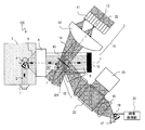
- FIG. 1 It is a figure which shows the specific structural example of the photoacoustic vibrometer of 1st Embodiment. It is a figure which shows the example in the case of comprising the photoacoustic vibrometer of 1st Embodiment as an ultrasonic diagnosing device.
- A It is a figure which shows the incident direction of the detection light beam 14 in the photoacoustic vibrometer of 1st Embodiment
- (b) is a figure which shows the other incident direction of the detection light beam 14.
- FIG. It is a figure which shows the structure and light ray of a cylindrical lens.
- FIG. 1 it is a diagram illustrating a configuration of an optical system that is configured by a cylindrical lens and has the functions of an image distortion compensation unit, 15 and an imaging lens system 16.
- FIG. 2nd Embodiment It is a figure which shows the structure of the image distortion compensation part 15 in the photoacoustic vibrometer of 2nd Embodiment. It is a figure which shows the structure of the image distortion compensation part 15 in the photoacoustic vibrometer of 3rd Embodiment. It is a figure which shows the structure of the photoacoustic vibrometer in 4th Embodiment. It is a figure which shows the structure of the photoacoustic vibrometer in 5th Embodiment. It is a figure which shows the method of detecting an ultrasonic wave with the probe used for the conventional ultrasonic diagnostic apparatus.
- a photoacoustic vibrometer includes an acoustic wave source, an acoustic lens system that converts a scattered wave generated by irradiating an object with an acoustic wave emitted from the acoustic wave source into a predetermined convergence state, and A detection light beam in which a photoacoustic medium portion arranged so that a scattered wave transmitted through the acoustic lens system is incident and a plurality of parallel monochromatic lights having different traveling directions are superimposed on each other, and the sound of the acoustic lens system
- a detection light source that emits a detection light beam that is incident on the photoacoustic medium unit at an angle that is non-perpendicular and non-parallel to an axis, and a reference light beam on which a plurality of monochromatic lights having different traveling directions are superimposed,
- a reference light source that emits a reference light beam superimposed on diffracted light by the detected light beam generated in the photoacoustic medium, an acou
- the frequencies of the detection light beam and the reference light beam may be different from each other.
- the reference light source may include at least one photoacoustic modulator.
- the reference light source may include a diffuser plate.
- the reference light source may include a fly-eye lens.
- Two optical systems including the imaging lens and the image receiving unit may be provided.
- the reference light source may include a polarizing plate.
- the image receiving unit may be a two-dimensional image sensor having a plurality of pixels arranged two-dimensionally.
- the photoacoustic vibrometer may further include an image processing unit that detects a temporal change in the amount of light detected by each pixel of the image receiving unit based on the electrical signal.
- the reference light source may include a shutter that controls the emission time of the reference light beam.
- the photoacoustic vibrometer may include at least three acoustic wave sources.
- the photoacoustic vibrometer may further include an image distortion correction unit that corrects distortion of at least one of the image of the object represented by the diffracted light and the electrical signal.
- the image distortion correction unit may include an optical member that enlarges the cross section of the diffracted light.
- the image distortion correction unit may include an optical member that reduces the cross section of the diffracted light.
- the optical member may include an anamorphic prism.
- At least one of the imaging lens and the optical member may include at least one cylindrical lens.
- the image distortion correction unit may correct image distortion of the object represented by the electric signal based on the electric signal.
- the spectral width of each monochromatic light is less than 10 nm, and the monochromatic light may be a plane wave having a wavefront accuracy of 10 times or less of the wavelength at the center frequency of the monochromatic light.
- the detection light source may include at least one fly eye lens.
- the acoustic lens system may include at least one of a refractive acoustic lens and a reflective acoustic lens.
- the acoustic lens system may include at least one acoustic element selected from a silica nanoporous material, a fluorine-based inert liquid, and polystyrene.
- the acoustic lens system may include at least one of a focal length adjustment mechanism and a focal position adjustment mechanism.
- the imaging lens system may include at least one of a focal length adjustment mechanism and a focal position adjustment mechanism.
- the photoacoustic medium part may contain at least one of a silica nanoporous material, a fluorine-based inert liquid, and water.
- the optical axis of the detection light beam emitted from the detection light source may be adjustable with respect to the sound axis of the acoustic lens.
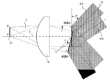
- FIG. 1 schematically shows the configuration of the photoacoustic vibrometer 100 according to the first embodiment.
- the photoacoustic vibrometer 100 includes an acoustic wave source 1, a photoacoustic medium unit 8, an acoustic lens system 6, a detection light source 19, a reference light source 23, an imaging lens system 16, and an image receiving unit 17 (image forming unit). And. Furthermore, the sound wave absorption end 10, the image distortion compensation unit 15, and the beam splitter 22 may be provided.
- the object 4 is disposed in the medium 3 through which the acoustic wave can propagate.
- the “medium 3 through which acoustic waves can propagate” is, for example, air, water, or the like.
- Body tissue is also a suitable example of “medium 3 capable of propagating acoustic waves”.
- An elastic body such as metal or concrete can also be used as the medium 3 because it transmits acoustic waves.
- the object 4 is a detection object having an elastic modulus different from that of the medium 3.
- the medium 3 is a body tissue
- the object 4 is an organ or tissue that is an observation target.
- the photoacoustic vibrometer 100 is used for nondestructive inspection of a structure
- the medium 3 is metal or concrete
- the object 4 is a structural defect such as a crack or a hole.
- the acoustic wave source 1 and the acoustic lens system 6 are disposed in direct contact with the medium 3 or indirectly through an intermediate layer. For example, when observing a body tissue of a subject, if the acoustic wave source 1 and the acoustic lens system 6 and the medium 3 are difficult to form a good contact state due to the surface shape of the medium 3, it is close to the medium 3.
- the acoustic wave source 1 and the acoustic lens system 6 may be brought into contact with the medium 3 through a gel material having acoustic characteristics.
- the photoacoustic vibrometer 100 irradiates the object 4 with an acoustic wave emitted from the acoustic wave source 1 and acquires the object 4 as a real image 18 that is an optical image.
- the real image 18 is an image obtained by scattering the acoustic wave 5 from the object 4. That is, the real image 18 is equivalent to a three-dimensional distribution of the elastic modulus inside and outside the object 4 observed from the direction of the sound axis 7. More specifically, the real image 18 is most focused on the two-dimensional distribution of the elastic coefficient of the object 4 on a plane perpendicular to the sound axis 7 and separated from the acoustic lens system 6 by the focal length f of the acoustic lens system 6.
- the real image 18 is an image in which the intensity of light changes at a frequency corresponding to the displacement velocity distribution on the object 4.
- the image receiving unit 17 measures the distribution state of the blinking period of the light intensity of the real image 18, acquires an image of the object 4 by the acoustic wave, and can measure the displacement velocity distribution.
- the acoustic wave source 1 irradiates the acoustic wave 2 toward the object 4.
- the frequency of the acoustic wave 2 suitable for observation of the target object 4 is selected according to the elastic characteristics of the target object 4 and the environment of the medium 3 around the target object 4.
- the acoustic wave 2 may be an ultrasonic wave used in a known ultrasonic diagnostic apparatus, for example, an ultrasonic wave having a frequency of several MHz to 10 MHz. .
- the acoustic wave 2 that is a burst wave is irradiated at least once on the object 4.
- the burst wave has a time waveform in which a sine waveform or a rectangular waveform having a constant amplitude and frequency, such as a plurality of the same sine waveform, continues for a certain period of time.
- the image receiving unit 17 performs imaging.
- the transmission time in the acoustic wave source 1 is controlled, the photographing time of the image receiving unit 17 is controlled, or both times are controlled.
- Acoustic wave 2 is generally a plane wave. Further, the acoustic wave 2 irradiates the region of the object 4 to be imaged with a substantially uniform intensity. In order to irradiate the object 4 with a substantially uniform intensity, the acoustic wave 2 may have a beam cross section larger than the imageable region of the photoacoustic vibrometer 100.
- a scattered wave 5 having the same frequency as that of the acoustic wave 2 is generated by reflection and diffraction inside and on the surface of the object 4.
- the scattered wave 5 is also a burst wave.
- the scattered wave 5 has a time waveform in which burst waves generated at each part of the object 4 are superimposed. For this reason, when the sound pressure is measured at one point in the medium 3, the sound pressure is observed as a time waveform in which a large number of burst waveforms having different amplitudes and timings are superimposed.
- the acoustic lens system 6 converts the scattered wave 5 into a plane sound wave 9 that propagates through the photoacoustic medium unit 8.
- the convergence of the scattered wave 5 by the acoustic lens system 6 is similar to the convergence of the light by the optical element in the optical field.
- Longitudinal waves (dense waves) generated when the acoustic wave propagates through the medium are generated at the interface between the media having different sound speeds. Realized by reflection and refraction.
- the acoustic lens system 6 may be described using terms in the optical field.
- the acoustic lens system 6 converges the scattered wave 5 generated at each point on the focal plane 21 into a predetermined state and converts it into a superimposed wave of plane sound waves having different propagation directions. Functions as an element.
- a detailed configuration of the acoustic lens system 6 will be described.
- the acoustic lens system 6 has a focal length f in the medium 3.
- the acoustic lens system 6 may be a refractive acoustic system or a reflective acoustic system.
- the acoustic lens system 6 includes an acoustic lens having at least one refracting surface and through which the scattered wave 5 passes.
- the acoustic lens is preferably made of an elastic body having a small acoustic wave propagation loss, such as a silica nanoporous material, water, a fluorine-based inert liquid such as fluorinate, or polystyrene.
- the acoustic lens system 6 When the acoustic lens system 6 is a reflective acoustic system, the acoustic lens system 6 has at least one reflecting surface made of a material that has a greatly different acoustic impedance from the medium 3 such as metal or glass. These refracting surfaces and reflecting surfaces have the same shape as the optical lens and the reflecting mirror, so that the scattered wave 5 can be converged.
- an antireflection film having the same function as an antireflection film formed to reduce reflection attenuation and stray light generated on the lens refracting surface in the optical field may be provided on the refracting surface of the acoustic lens system 6.
- it is made of an elastic body having an acoustic impedance equal to the geometric mean value of the acoustic impedances of the medium 3 and the acoustic lens, and has a thickness of 1/4 wavelength (the wavelength here is the wavelength at the frequency of the sine wave constituting the acoustic wave 2). ) May be provided as an antireflection film on the refractive surface that contacts the medium 3 of the acoustic lens.
- the object 4 is preferably located near the focal plane 21 of the acoustic lens system 6.
- the real image 18 of the object 4 becomes unclear as it deviates from the focal plane 21 of the acoustic lens system 6 as in an optical imaging device such as an optical camera.
- the focal plane 21 refers to a plane perpendicular to the sound axis 7 and separated from the acoustic lens system 6 in the direction of the object 4 by the focal length f of the acoustic lens system 6.
- the entire photoacoustic vibrometer 100 is moved so that the object 4 is positioned in the vicinity of the focal plane 21 of the acoustic lens system 6. It is preferable.
- the acoustic lens system 6 has a focus adjustment mechanism, like an imaging lens of an optical camera. May be further provided.
- a focal length adjustment function that is, a zoom function
- the function of the acoustic lens system 6 when the object 4 is located near the focal plane 21 will be described. Since the scattered wave 5 is a spherical wave centered at an arbitrary point on the focal plane 21, the spherical wave is propagated through the photoacoustic medium unit 8 by the acoustic lens system 6 and has a planar wavefront. Is converted to
- the plane sound wave 9 in the photoacoustic medium unit 8 is a sound wave on which plane sound waves having various traveling directions are superimposed.
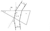
- FIG. 2 consider a case where a spherical wave is generated from a point A on the sound axis 7 of the acoustic lens system 6 and a point B away from the sound axis 7 on the focal plane 21.
- the acoustic lens system 6 converts the spherical wave generated at the point A into a plane wave having a plane wavefront A.
- the normal line of the wavefront A is parallel to the sound axis 7.
- the spherical wave generated at point B is also converted into a plane wave having a planar wavefront B.
- the normal of the wavefront B forms an angle ⁇ from the sound axis 7.
- the angle ⁇ is equal to Arctan (h / f).
- Arctan represents an arctangent function.
- the plane acoustic wave 9 shown in FIG. In addition, a very large number of plane waves are superimposed.
- the plane sound wave 9 has the same frequency as the acoustic wave 2. Further, as will be described in detail below, when the object 4 moves in a direction parallel to the sound axis 7, a Doppler shift due to the movement occurs in the frequency of the plane sound wave 9.
- the photoacoustic medium portion 8 is formed of an isotropic elastic body that has little propagation attenuation of the plane sound wave 9 and has translucency with respect to the detection light beam 14 described later.
- the sound velocity of the isotropic elastic body constituting the photoacoustic medium portion 8 is small.
- Suitable substances having such characteristics include, for example, silica nanoporous materials, fluorine-based solvents such as fluorinate, water, and the like.
- the photoacoustic medium unit 8 is preferably arranged with respect to the acoustic lens system 6 so that the plane sound wave 9 converted by the acoustic lens system 6 is incident on the photoacoustic medium unit 8 with low loss.
- the system 6 may be joined to the photoacoustic medium unit 8. Further, in order to suppress attenuation due to reflection on the joint surface, an antireflection film may be provided also on the joint surface.
- the acoustic lens system 6 may be provided on a part of the photoacoustic medium unit 8 (preferably the boundary surface with the medium 3). Good. In this case, the acoustic lens system 6 is composed of one refracting surface.
- the photoacoustic vibrometer 100 may include a sound wave absorption end 10.
- the sound wave absorption end 10 is provided on the surface opposite to the surface on which the acoustic lens system 6 of the photoacoustic medium unit 8 is provided, and absorbs the propagated plane sound wave 9 without reflection or scattering. Since all the sound waves that reach the sound wave absorption edge 10 are absorbed by the sound wave absorption edge 10, only the plane sound wave 9 exists in the photoacoustic medium unit 8. Sound waves other than the plane sound wave 9 are superimposed on the real image 18 as an image unrelated to the spatial distribution of the elastic coefficient of the object 4, that is, as noise. Therefore, the sound wave absorption end 10 functions as an element that reduces such noise.
- the acoustic impedance is substantially equal to that of the photoacoustic medium unit 8, and the propagation of the plane acoustic wave 9 is performed. It is preferable that the attenuation is large.
- Such materials include rubber and urethane.
- the sound wave absorption end 10 When the sound wave absorption end 10 is not used, for example, a photoacoustic medium portion 8 that is sufficiently long in the direction of the sound axis 7 may be used. In this case, the plane sound wave 9 is attenuated as it propagates through the photoacoustic medium unit 8, and the reflected wave generated at the end can be reduced.
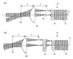
- the detection light source 19 generates a detection light beam 14 in which many plane wave light beams having different traveling directions are superimposed.
- the detection light beam 14 enters the photoacoustic medium unit 8 at a non-perpendicular and non-parallel angle with respect to the sound axis 7 of the acoustic lens system 6.
- Each plane wave light beam before being superposed is a plane wave and has high coherence. “High coherence” means that the wavelength, traveling direction, and phase are aligned.
- the detection light source 19 mainly includes, for example, a monochromatic light source 11, a beam expander 12, and a uniform illumination optical system 31.
- the monochromatic light source 11 generates a light beam having high coherence. Within the light beam, the wavelength and phase of the light are aligned. Specifically, the spectral width (half-value width) of the light beam emitted from the monochromatic light source 11 is preferably less than 10 nm.
- the luminous flux emitted from the monochromatic light source 11 is a plane wave having a wavefront accuracy of 10 times or less of the wavelength at the center frequency.
- the monochromatic light source 11 for example, a gas laser represented by a He—Ne laser, a solid laser, a semiconductor laser narrowed by an external resonator, or the like can be used.
- the light beam emitted from the monochromatic light source 11 may be continuous, or may be a pulsed light beam whose emission time can be controlled.
- a high-luminance real image 18 can be obtained.
- a silica nanoporous material is used as the photoacoustic medium portion 8
- a high-luminance real image 18 can be obtained by using a laser having a wavelength of 600 nm or more.
- the light beam emitted from the monochromatic light source 11 is split into two light beams by the beam splitter 33.
- One of the light beams is coupled to the single mode optical fiber 34 and guided to the reference light source 23.
- the light beam can be coupled to the single mode optical fiber 34 by condensing the light beam at the center of the core of the single mode optical fiber 34 with a focusing optical system such as a condenser lens.
- the light beam reflected by the beam splitter 33 is coupled to the single mode optical fiber 34, but the transmitted light beam may be guided to the reference light source 23.
- one of the divided light beams may be guided to the reference light source 23 by an optical system other than the single mode optical fiber 34, for example, a plurality of plane reflecting mirrors.
- the beam expander 12 is disposed on the optical axis 13 as an optical element next to the beam splitter 33.
- the beam expander 12 expands the aperture of the light beam emitted from the monochromatic light source 11 and emits a plane wave light beam 32 having an enlarged diameter.
- the aperture is enlarged, but the wavefront state of the light beam is maintained. For this reason, the light beam transmitted through the beam expander 12 is also a plane wave.
- the uniform illumination optical system 31 includes a fly-eye lens 41 and a condenser lens 42.
- the fly-eye lens 41 is composed of n small lenses arranged two-dimensionally. Each small lens has an optical axis parallel to the optical axis 13. Further, the focal points of the respective small lenses are all located on a focal plane 46 that is a plane perpendicular to the optical axis 13. Each small lens may have a different aperture shape, aperture diameter, and focal length.
- the focal length of the condenser lens 42 is fc.
- the optical axis of the condenser lens 42 coincides with the optical axis 13.
- the condenser lens 42 is disposed at a position away from the focal plane 46 by a distance fc.
- each small lens is formed on the focal plane 46.
- the total number of spots is n.
- the light beam focused on the spot becomes a spherical wave light beam centered on the spot and travels toward the condenser lens 42. Since the focal plane 46 is also the focal plane of the condenser lens 42, each spherical wave light beam is converted into a plane wave light beam by the condenser lens 42.
- each plane wave light beam is at a point on the optical axis that is separated from the condenser lens 42 by the focal length fc, that is, the focal point of the condenser lens 42. Proceed toward. For this reason, n plane wave beams equal to the number of small lenses are focused on the focal point of the condenser lens 42 at various incident angles.
- the plane including the focal point and perpendicular to the optical axis 13 is referred to as a uniform illumination plane 43.
- the incident angle is an angle between the optical axis 13 and the traveling direction of the light beam
- F number focal length / lens aperture diameter
- the fly-eye lens may be multi-staged as shown in FIG.
- the uniform illumination optical system 31 includes fly-eye lenses 44 and 45 provided between the condenser lens 42 and the beam expander 12. Three more light beams are obtained by the fly eye lens 45 from the light beams of one small lens constituting the fly eye lens 44. Accordingly, plane wave light flux three times the number of small lenses constituting the fly-eye lens 45 is incident on the uniform illumination surface 43 at different angles.
- the uniform illumination optical system 31 functions as an optical system for generating a light beam having a uniform illuminance distribution in addition to the function of generating a light beam group having different incident angles.
- the plane-wave light beam 32 emitted from the beam expander 12 has a Gaussian distribution intensity with rotational symmetry about the optical axis 13 in a plane perpendicular to the optical axis 13.
- the uniform illumination surface 43 the luminous flux incident on each small lens constituting the fly-eye lens 41 is enlarged and projected.
- a small lens having a sufficiently small aperture is used for the fly-eye lens, even if there is a light intensity distribution in the plane wave light beam 32, the light beam incident on each small lens is almost uniform because the aperture of each small lens is small. Has a light intensity distribution. A large number of such minute light beams are enlarged and superimposed on the uniform illumination surface 43. For this reason, the detection light beam 14 emitted from one illumination optical system 31 has a substantially uniform light intensity distribution on the uniform illumination surface 43.
- the illuminance distribution becomes flatter on the uniform illumination surface 43 as the aperture of each small lens is made smaller than the beam diameter of the plane wave beam 32 and the number of fly-eye lenses is increased. Note that the flattening of the illuminance distribution works extremely favorably in forming the real image 18 without illuminance unevenness.
- each component is arranged so that the uniform illumination surface 43 is located at the intersection of the sound axis 7 and the optical axis 13.
- the entire plane sound wave 9 can be illuminated with plane wave light beams having various incident angles.
- the uniform illumination surface 43 is illuminated by plane wave light beams having various incident angles. Since the uniform illumination surface 43 has the largest area illuminated by all of the plane wave luminous flux, the uniform illumination surface 43 is arranged at the intersection of the sound axis 7 and the optical axis 13 to detect a smaller luminous flux diameter.
- the entire plane sound wave 9 can be illuminated with the light beam 14. Therefore, in order to make the detection light source 19 small, it is preferable that the uniform illumination surface 43 includes the intersection of the sound axis 7 and the optical axis 13.
- the photoacoustic medium unit 8 when the plane sound wave 9 propagates through the photoacoustic medium unit 8, the photoacoustic medium unit 8 is densely and densely formed by the detected light beam 14 in the photoacoustic medium unit 8. Due to this density, diffracted light 201 is generated by Bragg diffraction of the detected light beam 14.
- Image distortion compensation unit 15 The generated diffracted light 201 has an intensity distribution reflecting the intensity distribution of the plane sound wave 9, that is, the two-dimensional distribution of the elastic characteristic of the object 4 on the focal plane 21. However, since the diffracted light 201 is emitted obliquely with respect to the sound axis 7 which is the traveling direction of the plane sound wave 9, the intensity distribution is distorted.
- the image distortion compensation unit 15 corrects the distortion of the diffracted light 201.
- the distortion of the diffracted light 201 may be performed by the image processing unit 20.
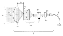
- Reference light source 23 The reference light source 23 emits a reference light beam 24 that is superimposed on the diffracted light 302 (or diffracted light 201) generated by the detected light beam 14 generated in the photoacoustic medium unit 8.
- the reference light source 23 includes a shutter 215, a photoacoustic modulator 214, a beam expander 213, a diffuser plate 212, and a condenser lens 211.
- the beam splitter 22 is used to superimpose the diffracted light 302 (or the diffracted light 201) and the reference light beam 24.
- the parallel light beam 216 is obtained by dividing the light beam emitted from the monochromatic light source 11 of the detection light source 19 and guiding it by the single mode optical fiber 34.
- the guided monochromatic light is converted into a plane wave light beam by a condenser lens (not shown) having a focal point on the core end face of the single mode optical fiber 34. Therefore, the parallel light beam 216 is a plane wave light beam having high coherence having the same frequency as the monochromatic light emitted from the monochromatic light source 11.
- the parallel light beam 216 enters the photoacoustic modulator 214 after passing through the shutter 215 for switching the light beam.
- the photoacoustic modulator 214 is an optical element that changes the frequency of monochromatic light in the parallel light beam 216 (that is, performs frequency modulation). More specifically, when the frequency of the parallel light beam 216 before entering the photoacoustic modulator 214 is ⁇ and the frequency of the sine wave signal input to the photoacoustic modulator 214 is f ′, the photoacoustic modulator 214.
- the output light beam has a frequency of ⁇ + f ′.
- the photoacoustic modulator 214 for example, an optical element in which a light beam is Bragg diffracted by the density of the acoustic propagation medium generated by acoustic waves propagating through the acoustic propagation medium can be used.
- tellurium dioxide is used as the acoustic propagation medium.
- the light intensity of the frequency-modulated parallel light beam 216 emitted from the photoacoustic modulator 214 generally depends largely on the frequency f ′ of the sine wave signal input to the photoacoustic modulator 214.
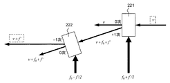
- the reference light source 23 may include a plurality of photoacoustic modulators. Good. Specifically, the reference light source 23 includes a first photoacoustic modulator 221 and a second photoacoustic modulator 222.
- the first photoacoustic modulator 221 and the second photoacoustic modulator 222 have the maximum diffraction efficiency (the light of the frequency-modulated light beam when the diffraction efficiency is maximized) when the frequency of the input sine wave signal is f 0. Strength is also maximized). Signals of frequencies f 0 + f ′ / 2 and f 0 ⁇ f ′ / 2 are input to the first photoacoustic modulator 221 and the second photoacoustic modulator 222, respectively, and +1 of the first photoacoustic modulator 221 is input.
- the first photoacoustic modulator 221 and the second photoacoustic modulator 222 are arranged so that the next diffracted light is incident on the second photoacoustic modulator 222.
- f ′ is about the same as f
- tellurium dioxide is used as the first photoacoustic modulator 221 and the second photoacoustic.
- f 0 is about 50 MHz to 150 MHz.
- f ′ is selected so that
- the ⁇ 1st order diffracted light emitted from the second photoacoustic modulator 222 becomes a light beam that is frequency-modulated at a frequency ⁇ + f ′.
- a high-intensity frequency-modulated parallel light beam 216 having a frequency ⁇ + f ′ is obtained. Note that the same frequency-modulated parallel light beam 216 can be obtained even when the order of the first photoacoustic modulator 221 and the second photoacoustic modulator 222 is reversed.
- the beam expander 213 converts the parallel light beam 216 modulated at the frequency ⁇ + f ′ into a light beam having a large beam cross-sectional diameter and irradiates the diffuser plate 212.
- the light beam having a large cross-sectional diameter need not be a plane wave.
- one convex lens or one concave lens may be used instead of the beam expander 213, it is desirable that the expanded light beam has a substantially uniform illuminance distribution in the light beam cross section.
- the diffuser plate 212 frosted glass or the like can be used.
- the surface roughness of the ground glass is preferably as small as possible. The reason is the following two points.
- the scattered light generated by the diffuser plate 212 has a strong light intensity in a direction parallel to the optical axis 217.
- a good reference light beam 24 can be generated even with a parallel light beam 216 having a lower intensity.
- the light intensity distribution in a cross section perpendicular to the optical axis 217 of the reference light beam 24 transmitted through the diffuser plate 212 is reflected in the real image of the object 4 detected by the image receiving unit 17, and the real image includes a speckle pattern. .
- a speckle pattern is a two-dimensional optical image in which light spots and dark spots are randomly distributed, and the scattered light generated from each point of minute irregularities on the surface of the diffuser plate 212 is superimposed to cause interference. causes speckle.
- a uniform illumination optical system using a fly-eye lens shown in FIG. When a uniform illumination optical system using a fly-eye lens is used, speckles can be prevented from occurring.
- the size of the light spot and the dark spot mainly depends on the combined focal length of the condenser lens 211 and the imaging lens system 16 and the condenser lens 211. It is determined from the opening diameter. The smaller the value obtained by dividing the combined focal length by the aperture diameter of the condenser lens 211, the smaller the size of the light spot and the dark spot.
- the photoacoustic vibrometer 100 in order to increase the measurement resolution of the displacement velocity distribution on the object 4, at least the size of the light spot and the dark spot of the speckle pattern on the light receiving surface of the image receiving unit 17 is required to receive the image.
- the resolution is smaller than the resolution of the image by the acoustic wave on the light receiving surface of the unit 17. Accordingly, it is preferable to reduce the size of the light spot and the dark spot on the light receiving surface of the image receiving unit 17, and it is preferable to use the condenser lens 211 having a larger aperture diameter and a short focal length fc2 . Assuming that the combined focal length is l, the aperture diameter is d, and the emitted light wavelength of the monochromatic light source 11 is ⁇ , the size ⁇ of the light spot and the dark spot on the light receiving surface of the image receiving unit 17 is 1.22 ⁇ ⁇ l / d. is there. Accordingly, the aperture diameter d and the focal length f c2 of the condenser lens 211 are determined so that ⁇ is equal to or less than the measurement resolution.
- Scattered light having the frequency ⁇ + f ′ is generated from each point on the diffuser plate 212 illuminated with the parallel light beam 216 modulated to the frequency ⁇ + f ′.
- the condenser lens 211 having a focal length f c2 is arranged at a distance f c2 away from the diffuser plate 212 to convert the scattered light from the diffuser plate 212 into a plane wave beam. Since the scattered light is generated from each point on the diffuser plate 212, the traveling direction of the plane wave light beam emitted from the condenser lens 211 is not parallel to the optical axis 217 of the condenser lens 211, and the angle thereof is on the diffuser plate 212 of the scattered light.
- the reference light source 23 shown in FIG. 6 includes a shutter 215 for turning on / off the reference light beam 24.
- a sine wave signal input to the photoacoustic modulator 214 may be turned on / off instead of the shutter 215.
- the reference light source 23 emits the reference light beam 24 having the frequency ⁇ + f ′, and the reference light source 23 is stopped while the sine wave signal is stopped.
- a light flux having a frequency ⁇ is emitted.
- Imaging lens system 16 and image receiving unit 17 The imaging lens system 16 condenses the diffracted light 302 on which the reference light beam 24 is superimposed on the light receiving surface of the image receiving unit 17.
- the image receiving unit 17 includes a plurality of pixels (photoelectric conversion elements) arranged two-dimensionally, two-dimensionally detects the condensed diffracted light 302, and outputs an electric signal.
- the generated electrical signal represents a two-dimensional distribution and a displacement velocity distribution of the elastic characteristics on the focal plane 21 of the object 4. By analyzing the obtained electrical signal, a two-dimensional distribution image of the elastic characteristics and displacement speed of the object can be obtained.
- the photoacoustic vibrometer 100 acquires an image of an acoustic wave of the object 4, that is, an image reflecting an elastic characteristic distribution and an image for measuring the displacement velocity distribution of each part of the object 4.
- acquisition of these two images will be described.
- the detection light beam 14 is composed of a large number of plane wave light beams having different traveling directions
- the plane sound wave 9 is also composed of a large number of plane sound waves having different traveling directions. Therefore, in the following description, it is assumed that the detection light beam 14 is composed of only a plane wave light beam having a wavefront perpendicular to the optical axis 13, and the plane sound wave 9 is composed of only a plane sound wave perpendicular to the sound axis 7.
- the detection light beam 14 is incident on the photoacoustic medium unit 8 obliquely so as to be non-perpendicular and non-parallel to the sound axis 7 of the acoustic lens system 6.
- the angle at which the sound axis 7 intersects the optical axis 13 of the detected light beam 14 is 90 ° ⁇ . That is, ⁇ represents the incident angle of the detected light beam 14 on the wavefront of the plane sound wave 9.
- ⁇ can be non-vertical and non-parallel, specifically any angle except 0 °, 90 °, 180 °, and 270 °. Only in this angle range ⁇ , Bragg diffraction occurs in the detected light beam 14 and diffracted light 201 is generated. A specific method of setting ⁇ for generating the diffracted light 201 will be described later.
- the emission time of the acoustic wave 2 is accurately controlled, and the plane sound wave 9 accurately reaches the uniform illumination surface 43 at the imaging time of the image receiving unit 17. ing.
- the positional error of the plane sound wave 9 in the photoacoustic medium unit 8 with a sound velocity of 50 m / s is 50 nm.
- this position error corresponds to a position error of 0.079 wavelength when converted to a He—Ne laser wavelength of 633 nm. From this, it is understood that the position of the plane sound wave 9 can be controlled in the photoacoustic medium unit 8 with very high accuracy by controlling the emission time of the acoustic wave 2.
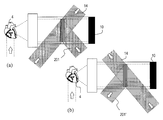
- FIG. 8A shows how the detected light beam 14 is Bragg diffracted by the plane sound wave 9 when the position of the detected light beam 14 and the position of the plane sound wave 9 are controlled as described above.
- FIG. 8A schematically shows the moment when the plane sound wave 9 passes through the optical path of the detection light beam 14.
- the plane sound wave 9 is a dense wave propagating in the photoacoustic medium unit 8. Therefore, a refractive index distribution proportional to the sound pressure distribution of the plane sound wave 9 is generated in the photoacoustic medium unit 8.
- the generated refractive index distribution has a period in the direction parallel to the sound axis 7 equal to the wavelength of the plane acoustic wave 9 and the refractive index distribution.
- the size changes in a sine wave shape, and a periodic structure having a uniform refractive index distribution in a direction parallel to a plane perpendicular to the sound axis 7 is obtained.
- Such a periodic refractive index distribution functions as a one-dimensional diffraction grating for the detection light beam 14. Therefore, when the detection light beam 14 is incident on the plane sound wave 9 at an angle ⁇ that satisfies the diffraction conditions described below, diffracted light 201 is generated. Since this one-dimensional diffraction grating has a flat grating surface and the wavefront of the detection light beam 14 is flat, the diffracted light 201 becomes a plane wave light beam.
- the acoustic wave 2 is composed of a sine wave whose number is sufficiently larger than two periods.
- a one-dimensional diffraction grating having a large number of grating surfaces operates as an amplitude-type phase grating, and the diffraction generated therein is Bragg diffraction.
- Bragg diffraction as shown in FIG. 8A, the angles formed by the detection light beam 14 and the diffracted light 201 with respect to the plane sound wave 9 are equal, and each is an angle ⁇ .
- the angle ⁇ is a discrete value that satisfies the Bragg diffraction condition described below.
- the diffracted light 201 is mainly generated by Raman-Nath diffraction.
- the angles formed by the detected light beam 14 and the diffracted light 201 with respect to the plane sound wave 9 do not have to be equal.
- Bragg diffraction produces diffracted light 201 having a higher intensity than Raman-Nath diffraction, which is suitable for observing the scattered wave 5 having a lower sound pressure.
- the diffracted light 201 generated mainly by Bragg diffraction is used using the acoustic wave 2 composed of many sine waves.
- the acoustic wave 2 composed of a sine wave of less than several tens of waves is used, so that Raman-Nath diffracted light is mixed in the diffracted light 201.
- the mixing of the Raman-Nath diffracted light into the diffracted light 201 works favorably in forming a good real image 18.
- FIG. 8B is a schematic diagram for explaining the Bragg diffraction condition in the one-dimensional diffraction grating generated by the plane sound wave 9.
- the grating interval of the diffraction grating 202 generated by the plane sound wave 9 is equal to the wavelength ⁇ a of the acoustic wave in the photoacoustic medium unit 8.
- One monochromatic light beam in the detection light beam 14 is defined as a monochromatic light 203.
- the wavelength of the monochromatic light 203 is ⁇ o.
- Equation (1) is the Bragg diffraction condition, and defines the angle ⁇ between the incident light beam and the outgoing light beam with respect to the lattice plane.
- Arcsin in Formula (1) represents an inverse sine function.
- Pure Bragg diffraction is a diffraction phenomenon that occurs in a state in which the diffraction grating 202 is composed of an infinite number of grating surfaces, and as shown in FIG. 8B, the angles of incident and outgoing rays with respect to the grating surface are equal. ⁇ .
- the diffraction grating generated by the plane sound wave 9 is an amplitude type diffraction grating having a sinusoidal amplitude distribution
- Raman-Nath diffracted light is generally mixed, high-order diffracted light with
- the diffracted light 201 has a light intensity distribution proportional to the sound pressure distribution on the wavefront of the plane sound wave 9 on the wavefront.
- the plane sound wave 9 generally has a non-uniform sound pressure distribution in the wavefront. Since the spatial distribution of the refractive index change in the photoacoustic medium unit 8 is proportional to the sound pressure distribution of the plane sound wave 9, the in-plane distribution of the refractive index change amount on the grating surface of the diffraction grating 202 is non-uniform.
- the refractive index distribution on the grating surface of the diffraction grating 202 is the same on all the grating surfaces. It is. Therefore, the diffraction grating 202 becomes a one-dimensional diffraction grating, and the diffracted light 201 is mainly generated by Bragg diffraction (as described above, in practice, Raman-Nath diffracted light is mixed slightly).
- the amplitude of the diffracted light 201 is proportional to the sound pressure distribution of the plane sound wave 9. Therefore, the light amplitude distribution on the wavefront of the diffracted light 201 is proportional to the sound pressure distribution of the plane sound wave 9.
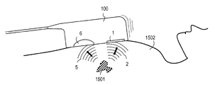
- FIG. 9A is a schematic diagram showing that the diffracted light 201 light beam contracts in one direction in the photoacoustic vibrometer 100.
- the detection light beam 14 must be incident on the plane sound wave 9 obliquely in order to satisfy the diffraction condition.
- the beam shape of the plane sound wave 9 is a circle having a diameter L
- the diffraction angle of the diffracted light 201 is ⁇ (the definition of ⁇ is the same as the description so far).
- the detection light beam 14 has a beam diameter including the plane sound wave 9 and the diffracted light 201 is generated only in the region where the plane sound wave 9 exists.
- the diffracted light 201 contracted in one direction is directly imaged by the imaging lens system 16 and a real image 18 is generated, the real image 18 becomes an optical image distorted in the y-axis direction, and the similarity between the object 4 and the real image 18 is obtained. Lost. That is, the diffracted light 201 has distortion in the y-axis direction. Therefore, the distortion of the diffracted light 201 is corrected by the image distortion compensation unit 15.
- the image distortion compensation unit 15 includes an anamorphic prism 301.
- anamorphic prism 301 With reference to FIG. 9B, the configuration and function of the anamorphic prism 301 will be described.
- FIG. 9B is a schematic diagram showing the configuration of the anamorphic prism 301. As shown in FIG. 9B, the anamorphic prism 301 is composed of two wedge-shaped prisms 303.
- FIG. 10 is a ray tracing diagram showing the state of light rays that pass through the wedge-shaped prism 303.
- the wedge-shaped prism 303 is in a medium having a refractive index of 1, and is made of a glass material having a refractive index n.
- the wedge-shaped prism 303 has a uniform column shape having the cross-sectional shape shown in FIG. 10, and FIG. 10 shows a cross-section of the wedge-shaped prism 303 in a plane including the normal lines of two surfaces sandwiching the acute angle ⁇ . Represents.
- the incident light and the outgoing light from the wedge-shaped prism 303 have different beam diameters.
- the luminous flux magnification calculated by L out / L in is expressed by the following equation (3).
- the anamorphic prism 301 is configured by combining one or more wedge-shaped prisms 303 shown in FIG. As shown in FIG. 9B, when two wedge-shaped prisms 303 having the same shape are used, the directions of the incident light and the emitted light to the anamorphic prism 301 can be made parallel to adjust the optical system. There is an advantage that it can be easily performed.
- the anamorphic prism 301 functions as an optical system for expanding the beam diameter.
- ⁇ and n of the wedge-shaped prism 303 and the incident angle ⁇ 1 are selected, and the diffracted light 201 is expanded by 1 / sin ⁇ times in the y-axis direction as shown in FIG. 9B.
- the distortion-compensated diffracted light 302 having a circular light beam cross section with a diameter L is obtained. Therefore, the diffracted light 302 after distortion compensation has a light amplitude distribution proportional to the sound pressure distribution on the wavefront of the plane sound wave 9 on its wavefront.
- the diffracted light 302 after distortion compensation has a different wavelength from the plane sound wave 9 that is an ultrasonic wave, but the sound pressure distribution on the wavefront of the plane sound wave 9 is entirely reproduced as a light amplitude distribution. It is compensated that a real image 18 similar to the object 4 is generated.
- the diffracted light 302 after distortion compensation is superimposed by the imaging lens system 16 having a focal length F after the reference light beam 24 generated by the reference light source 23 is superimposed when passing through the beam splitter 22. Focused. Since the diffracted light 302 and the reference light beam 24 are parallel light beams, they are condensed on the focal plane of the imaging lens system 16 to form a real image 18.
- the focal plane of the imaging lens system 16 is perpendicular to the optical axis of the imaging lens system 16 in the direction from the imaging lens system 16 toward the image receiving unit 17 when the focal length of the imaging lens system 16 is F.
- F refers to a plane apart.
- the focal plane of the imaging lens system 16 is provided so that the light receiving surface of the image receiving unit 17 is positioned, and the real image 18 on the focal plane is photographed as an optical image.
- the detection light beam 14 is composed of only a plane wave light beam having a wavefront perpendicular to the optical axis 13
- the plane sound wave 9 is composed of only a plane sound wave perpendicular to the sound axis 7.
- the object 4 is not a point on the sound axis 7 but has a finite size. Therefore, the plane sound wave 9 converted by the acoustic lens system 6 has many sound waves.
- a plane acoustic wave that is non-perpendicular to the axis 7 is included.
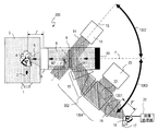
- the photoacoustic imaging device of the present embodiment generates Bragg diffracted light even when the detection light beam 14 is configured by superimposing a plurality of monochromatic lights having different traveling directions, even if the plane acoustic wave 9 has different traveling directions. be able to.
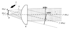
- spherical waves generated at two points A and B on the object 4 and on the focal plane 21 of the acoustic lens system 6 are converted into plane sound waves, thereby generating Bragg diffracted light.
- the situation is shown.
- the point A is located on the intersection of the sound axis 7 and the focal plane 21, but the point B is not located on the sound axis 7.
- the wavefront A of the plane sound wave due to the scattered wave 5 generated at the point A is a plane perpendicular to the sound axis 7.
- the wavefront B of the plane sound wave due to the scattered wave 5 generated at the point B outside the sound axis 7 is not a plane perpendicular to the sound axis 7, and the wavefront B forms an angle ⁇ with respect to the sound axis 7.
- the angle ⁇ is defined as in FIG.
- the angles of the sound axis 7 and the optical axis 13 are adjusted so that the plane wave light beam 911 is incident on the wavefront A at an angle ⁇ that satisfies the Bragg diffraction condition. Therefore, diffracted light is generated at the wavefront A.
- the incident angle of the plane wave light beam 911 with respect to the wavefront B is ⁇ , the Bragg diffraction condition is not satisfied, and no diffracted light is generated. Therefore, the diffracted light corresponding to the scattered wave 5 from the point B is not generated only by the plane wave light beam 911, and the optical image corresponding to the point B is missing from the real image 18.
- the wavefront B is irradiated with a plane wave light beam 912 inclined at an angle ⁇ clockwise from the optical axis 13. Since the plane wave light beam 912 is incident on the wavefront B at an angle ⁇ , diffracted light corresponding to the plane sound wave 9 from the point B is generated. Therefore, in this case, the optical image corresponding to the point B is not lost from the real image 18.
- both the plane wave light beam 911 and the plane wave light beam 912 are used.
- the photoacoustic vibrometer 100 that can capture an image of the object 4 with a wide viewing angle can be realized. Further, the image of the object 4 can be taken by detecting the diffracted light as an optical image without performing complicated signal processing such as delayed synthetic signal processing in a conventional ultrasonic diagnostic apparatus. For this reason, an image of the object 4 can be taken at high speed.
- the actual object 4 is composed of an infinite number of points.
- the plane sound wave 9 is a pulsed sound wave and is composed of a finite number of wavefronts. For this reason, the number of grating planes of the diffraction grating formed in the photoacoustic medium unit 8 is also finite.
- the diffracted light generated by the diffraction grating having the finite number of grating surfaces includes Raman-Nath diffracted light in addition to Bragg diffracted light. Since the diffraction conditions of Raman-Nath diffraction do not depend on the incident angle, for example, even when only the plane wave light beam 911 is irradiated, an optical image of not only the point A but also a nearby point is generated as a real image 18. Is done. Therefore, actually, the generated real image 18 is not a set of discrete points, but a continuous optical image similar to the object 4.
- all of the plurality of plane wave light beams superimposed by the detection light source 19 actually have a finite beam diameter.
- the fact that a parallel light beam has a finite beam diameter means that a “perfect” plane wave having various traveling directions is also superimposed on a plurality of superimposed parallel light beams.
- the “perfect” plane wave means a plane wave having a mathematically perfect plane, that is, a plane extending to infinity.
- the emitted light beam is a Gaussian beam
- the wavefront is not a mathematically perfect plane. This can be interpreted as a large number of “perfect” plane wave minute light beams superimposed.
- the plane light beam includes a minute plane wave light beam in which each plane wave light beam is superimposed innumerably. Therefore, the real image 18 obtained by the photoacoustic vibrometer 100 is not a set of discrete points but a continuous optical image similar to the object 4.
- the light beam expansion rate of the anamorphic prism 301 depends on the incident angle of the light rays to the anamorphic prism 301 (corresponding to the angle ⁇ 1 in FIG. 8). For this reason, the diffracted light generated according to the plurality of monochromatic lights superimposed on the plane wave luminous flux is incident on the anamorphic prism 301 at different incident angles, so that the luminous flux expansion ratio differs for each monochromatic light. As a result, even if the distortion of the image of the subject is corrected by the anamorphic prism 301, the real image 18 has distortion.
- the present embodiment includes an image processing unit 20 as shown in FIG. The image processing unit 20 performs image processing on the image data picked up by the image receiving unit 17 to correct distortion of the remaining real image 18 and obtain an image similar to the object 4.
- the distortion correction in the image processing unit 20 can be performed by calculation using the sound speed in the medium 3 and the photoacoustic medium unit 8 and the sound collection / condensation characteristics of the acoustic lens system 6 and the imaging lens system 16.
- the medium 3 is a body tissue
- the sound speed or the like of the medium 3 may vary greatly depending on the individual difference of the subject or a state difference such as body temperature.
- a reference test piece such as a medium modeled according to individual differences or state differences, and an elastic object whose shape and dimensions are known, is used as the object 4 to obtain a reference test piece.
- the distortion correction amount in the image processing unit 20 can be determined by calibrating so that the obtained real image 18 is correctly a similar image of the reference test piece.
- the image processing unit 20 does not have to perform distortion correction on the real image 18.
- the photoacoustic vibrometer 100 can be regarded as a modified optical system of a double diffractive optical system composed of two optical lenses having focal lengths f and F.
- FIG. 12A is a schematic diagram for explaining the operation of the double diffractive optical system in the optical field.
- the lens 403 and the lens 404 have focal lengths f and F, respectively.
- the lens 403 and the lens 404 are arranged at two points on the optical axis 409 that are separated from each other by a distance f + F.
- the optical axes of the lens 403 and the lens 404 coincide with the optical axis 409.
- a convex lens having a focal length fl has a focal point at two points on the optical axis that are separated from the lens by the center of the lens.
- Fourier optics an object placed at one focal point of a convex lens and an optical image at the other focal point are in a relationship transformed by Fourier transformation.
- a Fourier transform image of the object 401 by the lens 403 is formed on the Fourier transform surface 402 that is another focal plane (that is, a plane that includes the focal point and is perpendicular to the optical axis). Since the Fourier transform surface 402 is also the focal plane of the lens 404, a Fourier transform image of the Fourier transform image of the object 401 formed on the Fourier transform surface 402 is formed on the other focal plane of the lens 404. That is, the optical image formed on the other focal plane of the lens 404 corresponds to the object 401 subjected to Fourier transform twice.
- the real image 405 that is the two Fourier transform images of the object 401 is a figure similar to the object 401. It becomes. Note that the real image 405 appears on the focal plane of the lens 404 as an inverted image of the object 401, and the size of the real image 405 is F / f times that of the object 401 because the focal lengths of the lens 403 and the lens 404 are different. In this way, in the double diffractive optical system of FIG. 12A, an optical image similar to the object 401 appears as a real image 405, and the focal point on which the real image of the lens 404 is formed on an imaging device such as a CCD If installed on the surface, the object 401 can be imaged.
- the photoacoustic vibrometer 100 of this embodiment can be regarded as a double diffractive optical system in which one of the two optical systems is replaced with an acoustic system.
- the generation of the diffracted light 201 and the correction of the diffracted light 201 in the photoacoustic vibrometer 100 are the amplitudes on the wavefront of the plane sound wave 9 that is a plane wave having the wavelength ⁇ a.
- the distribution (sound pressure) can be regarded as an acousto-optical converter that transfers the distortion distribution (light) of the diffracted light 302 after distortion compensation, which is a plane wave of wavelength ⁇ o.
- the photoacoustic mixed optical system in the photoacoustic vibrometer 100 has a wavelength between the double diffractive optical system constituted by the acoustic lens system 6 and the imaging lens system 16, as shown in FIG. Functions as a photoacoustic system in which an acousto-optic converter 406 for converting ⁇ a to ⁇ o is inserted. Accordingly, in the double diffractive photoacoustic system of FIG. 12B, the real image 408 becomes an optical image similar to the object 407 and is on the focal plane of the imaging lens system 16 by Fourier optics. Inverted and inverted at
- the size of the real image 408 with respect to the object 407 is (F ⁇ ⁇ o) / (f ⁇ ⁇ a) times.
- F / f is set to be large (F ⁇ ⁇ o) /
- the photoacoustic vibrometer converts a scattered wave from an object into a plane sound wave by an acoustic lens system lens, and generates diffracted light by a detection light beam on which a plurality of monochromatic lights having different traveling directions are superimposed.
- An optical image of the object 4 can be taken by detecting the diffracted light in two dimensions by the image receiving unit. Since a real image of an object can be passively formed without the need for signal processing such as delay processing in a conventional ultrasonic diagnostic apparatus to form a real image of the object, an image of the object can be acquired at high speed. it can. Further, since a real image of the object can be passively formed, the displacement velocity distribution of the object can be measured as will be described below.
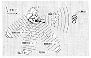
- the photoacoustic vibrometer 100 measures a displacement velocity distribution of the object 4 by observing a frequency change generated in a scattered sound wave from a moving object called Doppler shift.
- Doppler shift a frequency change generated in the scattered sound wave generated by the moving object during acoustic wave ultrasonic irradiation
- FIG. 13 schematically shows a state in which the object 4 is arranged in the medium 3, the acoustic wave 2 propagates, and the scattered wave 5 is generated.
- the propagation speed of the acoustic wave 2 in the medium 3, that is, the sound speed is V.
- the object 4 is moving or deforming periodically or aperiodically in time, and at a certain time, an arbitrary position x on the object 4 is a velocity v (x) (position x and velocity Assume that v (x) is displaced by a vector amount).
- the velocity v (x) may have a different magnitude and direction for each position x.
- the acoustic wave 2 is a plane sound wave having a frequency f.
- the traveling direction of the acoustic wave 2 is e i (e i is a vector of magnitude 1), and the direction vector representing the direction from the position x to the observer 231 is e o (e o is also a vector of magnitude 1). To do.
- the Doppler shift 233 is a function of the three vectors e i , e o , and v (x) described above, and a specific function form thereof is given by Expression (4).
- v (x) ⁇ e i is two vector quantity v (x), representing the inner product of e i.
- v (x) ⁇ e o is two vector quantity v (x), representing the inner product of e o.
- the scattered wave 5 from each point has a different frequency. Therefore, the projection component of the by measuring the Doppler shift 233 of the scattered waves from the position x, contrary to the position x of the velocity vector v (x) (to be precise, the vector e i, v in the e o direction (x) ) Can be estimated. Therefore, the distribution of the displacement speed can be measured.
- the photoacoustic vibrometer 100 detects the Doppler shift 233 caused by the displacement of the object 4 described above as the blinking cycle of the light intensity of the real image 18. The detection is performed based on an electric signal obtained from the image receiving unit 17 in the image processing unit 20, for example. For the sake of explanation, as shown in FIG. 14, it is assumed that two different points A and B on the object 4 are moving at different velocity vectors v (x A ) and v (x B ), respectively. When the object 4 is irradiated with the acoustic wave 2 having the frequency f, scattered waves 5 are generated from the two points A and B, respectively.
- the scattered wave 5 from each point is converted into a plane acoustic wave having wavefronts A and B different from each other. Since the two points A and B have different velocity vectors v (x A ) and v (x B ), as described with reference to FIG. 13, the scattered wave 5 from each point has a different Doppler shift ⁇ f (x A ), ⁇ f (x B ). Accordingly, the plane sound waves having the wavefront A and the wavefront B converted by the acoustic lens system 6 have different frequencies f + ⁇ f (x A ) and f + ⁇ f (x B ), respectively.
- the scattered wave 5 Since the scattered wave 5 is generated from all the points x on the focal plane 21, the scattered wave 5 that has passed through the acoustic lens system 6 has a plane sound wave having a frequency f + ⁇ f (x) and traveling in different directions.
- the superposed plane sound wave 9 is obtained.
- the diffracted light 201 is emitted from each plane wave.
- the diffracted light 201 includes information on the sound pressure intensity distribution and propagation direction of each plane sound wave, and also includes information on the Doppler shift ⁇ f (x) of each plane sound wave.
- ⁇ f Doppler shift
- FIG. 15 when a detection light beam 14 having a frequency ⁇ is incident on a plane sound wave 9 having a frequency f at an angle ⁇ that satisfies the Bragg diffraction condition, diffracted light 201 is generated.
- the frequency of the diffracted light 201 changes by the frequency f of the plane sound wave 9 (that is, subjected to frequency modulation) as compared with the frequency of the detected light beam 14.
- the frequency of the diffracted light 201 is + 1st order diffracted light
- the frequency of the diffracted light 201 is ⁇ + f
- the frequency increases by the frequency f of the plane sound wave 9. Note that the frequency change does not occur in the 0th-order diffracted light (still ⁇ ).
- the diffracted light 201 includes frequency information in addition to the sound pressure intensity distribution and propagation direction of the plane sound wave 9.
- FIG. 16 shows a ray tracing diagram when the reference light source 23 is omitted.
- the point that the real image 18 similar to the object 4 is projected onto the light receiving surface of the image receiving unit 17 by the photoacoustic vibrometer 100 is as described above.
- attention is paid to two points A and B on the object 4.
- the acoustic lens system 6 converts the sound waves into plane sound waves having frequencies f + ⁇ f (x A ) and f + ⁇ f (x B ), respectively.
- the plane sound wave is illuminated with a detection light beam 14 having a frequency ⁇ , and diffracted light corresponding to two points A and B is generated by Bragg diffraction. Each diffracted light is subjected to frequency modulation by a plane sound wave.
- the frequencies of the diffracted light are ⁇ + f + ⁇ f (x A ) and ⁇ + f + ⁇ f (x B ).
- the diffracted light is condensed as light spots at points A ′ and B ′ on the real image 18 by the distortion compensator 15 and the imaging lens system 16.
- Each light spot has a different frequency ⁇ + f + ⁇ f (x A ), ⁇ + f + ⁇ f (x B ).
- the light spot that forms the real image 18 corresponding to the displacement velocity vector distribution v (x) on the object 4 has the frequency distribution ⁇ + f + ⁇ f (x).
- the velocity vector distribution v (x) on the object 4 can be measured by measuring the frequency distribution ⁇ + f + ⁇ f (x).
- ⁇ + f + ⁇ f (x) is a very high frequency having the same order as the frequency of visible light, measurement is generally not easy.
- the photoacoustic vibrometer 100 measures ⁇ f (x) by superimposing the reference light beam 24 generated by the reference light source 23 on the diffracted light 302 after distortion compensation and using interference. For example, when two monochromatic light beams having a frequency ⁇ and a frequency ⁇ + ⁇ (where ⁇ >> ⁇ ) are superimposed and interfered, beat light whose light intensity varies at the frequency of the difference frequency ⁇ is generated.
- the photoacoustic vibrometer 100 utilizes this principle.
- the beam splitter 22 superimposes the reference light beam 24 generated by the reference light source 23 on the diffracted light 302 after distortion compensation, and the generated beat light is converged by the imaging lens system 16 to form a real image 18.
- the two points on the real image 18 corresponding to the two points A and B on the object 4 are A ′ and B ′, respectively, and the light on the two points A ′ and B ′.
- the distortion-compensated diffracted light 302 that forms a point undergoes frequency modulation and has frequencies ⁇ + f + ⁇ f (x A ) and ⁇ + f + ⁇ f (x B ).
- the reference light beam 24 is a light beam on which a plane wave light beam having a frequency ⁇ + f ′ having various traveling directions is superimposed. Therefore, by superimposing the reference light beam 24 on the diffracted light 302 after distortion compensation by the beam splitter 22, the frequency ⁇ + f ′ having a wavefront coincident with each plane wave light beam forming the light spots A ′ and B ′. It is possible to generate beat light by interfering with plane wave light flux. As a result, the light spots A ′ and B ′ on the real image 18 become beat light whose intensity varies depending on the difference frequency between the diffracted light 302 after distortion compensation and the reference light beam 24.
- the fluctuation frequencies of the light intensity at the light spots A ′ and B ′ are ⁇ f (x A ) + (f ⁇ f ′) and ⁇ f (x B ) + (f ⁇ f ′), respectively. These light intensity fluctuation cycles are sufficiently slow and can be measured.
- the real image 18 in the photoacoustic vibrometer 100 is an optical image composed of light spots having different blinking speeds depending on positions. More specifically, the real image 18 is an optical image that blinks at a beat frequency ⁇ f (x) + (f ⁇ f ′) corresponding to the velocity vector distribution v (x) on the object 4.
- a method for measuring the beat frequency distribution ⁇ f (x) + (f ⁇ f ′) of the real image 18 in the photoacoustic vibrometer 100 will be described with reference to FIG.
- a high-speed image sensor having a frame rate several times or more the beat frequency ⁇ f (x) + (f ⁇ f ′) is used.
- a high-speed image sensor having a global shutter such as a CCD (solid image receiving element) in which a plurality of pixels are arranged in two dimensions is used. be able to.
- the global shutter is an image acquisition method in which the imaging timings of all the pixels are the same.
- the temporal change in light intensity for each pixel 281 is measured based on the acquired image data (consisting of a plurality of frames). Then, the beat frequency for each pixel 281 is obtained from the time variation of the measured light intensity.
- the Doppler shift ⁇ f (x) is calculated from the beat frequency for each pixel 281. Can do.
- a velocity vector distribution v (x) on the object 4 is calculated from the obtained Doppler shift ⁇ f (x). Specifically, the velocity vector distribution v (x) is calculated using Equation (5) derived from Equation (4).
- the constant k in the equation (5) is obtained from the measured Doppler shift ⁇ f (x) and the frequency f of the acoustic wave 2, and the vectors e i and e o are obtained from the apparatus configuration of the photoacoustic vibrometer 100 and the captured image. Obtainable. Therefore, the magnitude of the velocity vector distribution v (x) in the vector e i + (k ⁇ 1) eo direction can be obtained from the measured Doppler shift ⁇ f (x). In this way, the photoacoustic vibrometer 100 uses the beat frequency distribution ⁇ f (x) + (f ⁇ f ′) of the real image 18 to determine the velocity of the object 4 in the vector e i + (k ⁇ 1) eo direction. The magnitude of the vector distribution v (x) can be measured.
- equation (5) is a linear equation for the three-component unknown function v (x), and therefore has a solution for m 0 ⁇ 3 independent equations.
- the velocity vector distribution v (x) as a vector quantity can be measured.
- the frequencies of the acoustic waves 2 emitted from the different acoustic wave sources 1 are different.
- different acoustic wave sources 1 emit acoustic waves 2 having the same frequency, it is preferable to shift the emission timing.
- the imaging of the image by the acoustic wave in the photoacoustic vibrometer 100 and the measurement of the velocity vector distribution v (x) can be performed, for example, by the following procedure.
- FIG. 20A using two pieces of image data captured by the image receiving unit 17 at different times, an image of an object is captured and a velocity vector v (x) is measured from each image data. Do. It is preferable that the acquisition times of the two image data are close so that the object 4 can be regarded as stationary during the measurement. Specifically, for example, first, the shutter 215 (FIG. 6) of the reference light source 23 is closed, and the object 4 is imaged by acoustic waves.
- the shutter 215 is opened, image data on which the reference light beam 24 is superimposed is acquired, and the velocity vector distribution v (x) is measured by the method described with reference to FIG.
- the light intensity distribution of the reference light beam 24 emitted from the reference light source 23 is uniform, but includes a speckle pattern. Therefore, the real image 18 generated when the reference light beam 24 overlaps and interferes with the real image 18 of the object 4 is superposed on the speckle pattern, and deteriorates compared to the real image 18 when the reference light beam 24 does not overlap.
- a high-definition image and a displacement velocity distribution image can be obtained by capturing the image of the object and measuring the velocity vector v (x) in different frames.
- the shutter 215 of the reference light source 23 may be kept open, and only the optical image on which the speckle pattern by the reference light beam 24 is superimposed may be acquired.
- the speckle pattern is removed by image filtering, and the reference light beam 24 is not superimposed.
- the optical image of the object 4 is reproduced.
- a technique for removing speckle patterns by image processing has been established. For example, by using a speckle noise reduction filter, an optical image without a speckle pattern with high accuracy, that is, a target when there is no superimposition of a reference light beam 24. An optical image of the object 4 can be reproduced. According to this method, since image capturing and measurement of the displacement velocity distribution v (x) are performed from one image data, it is possible to speed up the measurement.
- the photoacoustic vibrometer of the present embodiment superimposes the reference light on which a plurality of monochromatic lights having different traveling directions are superimposed on the diffracted light described above, and two-dimensionally detects it by the image receiving unit.
- the Doppler shift which arises when each part of a target object is displaced can be detected as a luminance change in each part.
- FIG. 21 shows a specific configuration example of the photoacoustic vibrometer 100.
- the configuration of the apparatus shown in FIG. 21 irradiates the internal organs from outside the body with acoustic waves 2 as in the case of an ultrasonic diagnostic apparatus, images the organs such as the heart wall and the arterial blood vessel wall, and the movement / displacement state of the organs. Suitable for observation.
- the medium 3 when observing an internal organ, the medium 3 is a body tissue.
- a burst signal composed of 20 sine waves having a frequency of 13.8 MHz is emitted from the acoustic wave source 1 as the acoustic wave 2.
- the signal duration of this burst signal is 1.4 ⁇ sec (1.4 ⁇ 10 ⁇ 6 seconds). Since the sound velocity in the body tissue is about 1500 m / s, the wavelength of the acoustic wave 2 in the body tissue is about 110 ⁇ m, and the physical signal length measured in parallel with the traveling direction of the acoustic wave 2 is about 2.2 mm. Therefore, in the photoacoustic vibrometer shown in FIG. 21, the object 4 vibrating at a maximum frequency of several hundred kHz can be photographed with a spatial resolution of several hundred ⁇ m.
- a silica nanoporous body having a sound velocity of 50 m / s is used as the photoacoustic medium portion 8. Since the silica nanoporous material has a low sound velocity and a short propagation wavelength of ultrasonic waves, a large diffraction angle can be obtained. In addition, the silica nanoporous material has sufficient translucency with respect to the He—Ne laser beam having a wavelength of 633 nm, and is preferably used in the configuration example shown in FIG.
- a fluorinated solvent such as fluorinate having a high light-transmitting property is also a low sound velocity (sound velocity of about 630 m / s) medium, and can be suitably used as the photoacoustic medium portion 8.
- the diffraction angle of the first-order diffracted light is about 5 °.
- the beam expansion ratio that must be realized by the image distortion compensator 15 is about 5.74, which can be compensated by a commercially available anamorphic prism.
- a high-sensitivity image sensor is used as the image receiving unit 17 in order to observe a tissue with low light intensity of the generated diffracted light. Further, from the viewpoint of image quality and light quantity, in order to capture the real image 18 at the moment when the plane sound wave 9 crosses the detected light beam 14, and further to observe the movement of the object 4 through measurement of the Doppler shift amount by continuous shooting, the image receiving unit As the image sensor 17, an image sensor capable of imaging at high speed is applied. The frame rate of the image sensor used as the image receiving unit 17 can be appropriately selected according to the displacement speed of the object 4.
- a high-speed CCD image sensor Charge Coupled Device Image Sensor
- the image receiving unit 17 a high-speed CCD image sensor (Charge Coupled Device Image Sensor) of about 2000 frames / second is used as the image receiving unit 17.
- an image intensifier may be placed in front of the image sensor to increase the brightness of the real image 18.
- a higher output monochromatic light source 11 may be used.
- the image sensor has a global shutter as described above.
- the reflected wave of the ultrasonic wave is generated at the interface between the acoustic media having different acoustic impedances, and the luminance and image quality of the real image 18 are lowered. Higher intensity reflection occurs at the interface where the acoustic impedance difference is larger. Therefore, in the configuration example shown in FIG. 21, a matching layer (B) 2106 that functions as an antireflection film is provided at the interface between the acoustic lens system 6 and the photoacoustic medium unit 8.
- the body tissue as the medium 3 has acoustic characteristics (sound speed 1500 m / s, density 1 g / cm 3 ) comparable to water
- the photoacoustic medium part 8 has a sound speed 50 m / s and density 0.11 g. / Cm 3 silica nanoporous material
- a 6.7 ⁇ m thick thin film made of silica nanoporous material having a sound velocity of 367 m / s and a density of 0.27 g / cm 3 is made of polystyrene having a thickness of 140 ⁇ m (one wavelength matching film).
- the size of the real image 18 with respect to the object 4 is (F ⁇ ⁇ o) / (f ⁇ ⁇ a) times.
- the wavelength ⁇ o of the light is 633 nm
- the wavelength ⁇ a of the ultrasonic wave of 13.8 MHz in the silica nanoporous material having a sound velocity of 50 m / s is 3.6 ⁇ m.
- F / f 1.14. Therefore, when the acoustic lens system 6 having a focal length of 103 mm is used, the imaging lens system 16 having a focal length of 117 (1.14 ⁇ 103) mm may be used.
- the focal length of the imaging lens system 16 is increased and the photoacoustic vibration is increased.
- the outer shape of the imaging lens system 16 can be reduced by using, for example, a reflection optical system typified by a Cassegrain optical system as the imaging lens system 16.
- the distance between the imaging lens system 16 and the real image 408 can be arranged closer to the actual focal length F, and the photoacoustic vibrometer 100 can be downsized.
- the photoacoustic vibrometer 100 can also be reduced in size by arranging the distance between the acoustic lens system 6 and the imaging lens system 16 closer than f + F.
- the photoacoustic mixed optical system of the photoacoustic vibrometer 100 can be regarded as a double diffractive optical system in the optical field. According to the basic configuration of the double diffractive optical system, the acoustic lens system 6 and the imaging lens system 16 are arranged apart from each other by the sum f + F of the focal lengths of the lenses.
- the optical image formation of the real image 408 is not affected.
- the distance between the acoustic lens system 6 and the imaging lens system 16 can be shortened below f + F.
- the photoacoustic vibrometer 100 can be further reduced in size.
- the photoacoustic vibrometer 100 can be used as a visualization device that non-invasively observes an internal organ 1501 used in medical diagnosis or the like.
- the photoacoustic vibrometer 100 is integrated into one unit as in the conventional ultrasonic probe. In this unit, all of the apparatus configuration shown in FIG. 1 or all of the apparatus configuration excluding the monochromatic light source 11 is integrated.
- the photoacoustic vibrometer 100 is brought into contact with the body surface of the subject 1502, and the acoustic wave 2 generated from the acoustic wave source 1 is transmitted from outside the body into the body.
- a matching method for example, a matching gel or cream used in a conventional ultrasonic diagnostic apparatus may be used, or an acoustic impedance matching layer may be provided on the surface of the acoustic wave source 1.
- a part of the acoustic wave 2 traveling through the body is scattered by the organ 1501 and becomes a scattered wave 5.
- the scattered wave 5 that has reached the acoustic lens system 6 is converted into a plane wave by the acoustic lens system 6, and an image of the organ 1501 is acquired by the operation of the photoacoustic vibrometer 100 described above.
- Imaging of an organ 1501 that is in a plane perpendicular to the sound axis 7 (not shown) of the photoacoustic vibrometer 100 and is outside the imaging region is performed by moving the photoacoustic vibrometer 100 on the body surface in the same manner as a conventional ultrasonic probe. By doing. Further, imaging of organs at different depths in the body is performed by the focal length adjustment mechanism 2108 of the acoustic lens system 6.
- the photoacoustic vibrometer 100 may include a focal length variable mechanism provided in the imaging lens system 16.
- a zoom function can be realized.
- the similarity ratio between the object 4 and the real image 18 can be changed, and observation of a more detailed portion of the object 4 and observation of a wider area are facilitated.
- the detection light beam 14 is irradiated while being inclined from the sound wave absorption end 10 side toward the object 4.
- the detection light beam 14 may be irradiated at an angle from the object 4 side to the sound wave absorption end 10 side.
- the diffracted light 201 ' is emitted to the object 4 side.
- a real image having a mirror image relationship in which the paper surface of FIG. 12B is a mirror image symmetry plane is obtained with respect to the real image obtained by the arrangement of FIG. Therefore, in order to obtain the real image 18 of the object 4 in the correct orientation, the photographed image is reflected once by a plane mirror or the like so that it is optically mirror-inverted, or mirror image inversion is performed by the image processing unit 20. Do.
- the anamorphic prism 301 is used as the image distortion compensation unit 15, but another optical system having the same function may be used for the image distortion compensation unit 15.
- the image distortion compensation unit 15 may be configured using two condensing cylindrical lenses.
- the cylindrical lens 151 functions as a condensing lens in a plane parallel to the yz plane of the coordinate system set in the figure, but has a condensing function in a plane parallel to the xz plane.
- Optical element As shown in FIG. 25, the optical system in which the two cylindrical lenses having mutually converging planes orthogonal to each other operate as an optical system having the functions of the image distortion compensation unit 15 and the imaging lens system 16. .
- the cylindrical lens 161 and the cylindrical lens 162 are arranged in the direction shown in FIG.
- the cylindrical lens 161 has a longer focal length than the cylindrical lens 162, and the focal points of the two lenses coincide.
- the optical system configured by the cylindrical lenses 161 and 162 functions as an optical system that forms an image at different ratios on the yz plane and the xz plane.
- the focal length of both lenses so as to compensate for the flatness sin ⁇ of the light flux in FIG. 3, that is, the ratio of the image in the y-axis direction to the x-axis direction is 1 / sin ⁇ .
- the focal length of the cylindrical lens 162 may be set to be sin ⁇ times the focal length of the cylindrical lens 161.
- the focal length of the cylindrical lens 161 is determined by the similarity ratio between the object 4 and the real image 18.
- the photoacoustic vibrometer 100 can acquire high-definition and high-speed images, and can observe the elastic characteristics of an organ without requiring a special examination environment depending on the examination object.
- the displacement velocity distribution of each part of the organ can be measured.
- FIG. 26 schematically illustrates the configuration of the image distortion compensation unit 15 in the present embodiment.
- the detection light beam 14 generated by the detection light source 19 is superimposed with a large number of plane wave light beams having different traveling directions. Below, it demonstrates paying attention to the plane wave light beam parallel to the optical axis 13 among those plane wave light beams.
- the image distortion compensation unit 15 compensates for the distortion of the light flux by multiplying by 1 / sin ⁇ in the y-axis direction at the coordinates set in FIG.
- the image distortion compensation unit 15 is realized by an optical system using an anamorphic prism or a cylindrical lens that is an optical element.
- the function of the image distortion compensation unit 15 is realized by a non-optical method.
- the distorted diffracted light 201 is imaged by the imaging lens system 16.
- the real image 801 is distorted in the y-axis direction, but the real image 801 is acquired by the image receiving unit 17 in this state.
- the image processing unit 20 receives an electrical signal indicating the real image 801 from the image receiving unit 17 and removes image distortion of the real image 801 by image processing.
- an image similar to the object 4 is generated by performing image processing for multiplying the real image 801 by 1 / sin ⁇ in the y direction.
- the number of optical elements to be used can be reduced. Further, since the function of the image distortion compensation unit 15 is realized in the image processing unit 20, a space for providing the optical image distortion compensation unit 15 is not necessary. Therefore, manufacturing cost can be suppressed and a small photoacoustic vibrometer can be realized.
- the optical image distortion compensation unit 15 shown in FIG. 9B and the image distortion compensation unit 15 by image processing in the image processing unit 20 may be used in combination.
- the aberration correction may be performed by the image processing unit 20.
- FIG. 27 schematically illustrates the configuration of the image distortion compensation unit 15 in the present embodiment.
- the image distortion compensator 15 of the present embodiment has the light beam of the diffracted light 201 in the x-axis direction of the set coordinates in FIG.
- a reduction optical system 901 that multiplies the width by sin ⁇ is included. If the cross-sectional shape of the sound bundle of the plane sound wave 9 is a circle having a diameter L, the cross-sectional shape of the light beam of the diffracted light 201 is an ellipse of L in the x-axis direction and L ⁇ sin ⁇ in the y-axis direction.
- the cross-sectional shape of the light beam of the diffracted light 902 after distortion compensation is a circle having a diameter L ⁇ sin ⁇ .
- the image distortion compensator 15 corrects the diffracted light 201 to a light beam having a diameter L, but in this embodiment, corrects the light beam to a light beam having a diameter L ⁇ sin ⁇ .
- the focal length of the acoustic lens system 6 is f
- the focal length of the imaging lens system 16 is F
- the wavelength of the plane sound wave 9 that is an ultrasonic wave is ⁇ a
- monochromatic light is ⁇ a
- ⁇ o is the wavelength of the detection light beam 14
- ⁇ is the diffraction angle.
- the cross-sectional shape of the diffracted light 902 after distortion compensation is circular, so that the real image 18 is similar to the object 4.
- the similarity ratio is ( ⁇ a ⁇ f) / ( ⁇ o ⁇ F) ⁇ sin ⁇ .
- the similarity ratio is 1/2 ⁇ (f / F).
- the reduction optical system 901 makes the similarity ratio independent of the wavelengths of the ultrasonic wave and the monochromatic light.
- the similarity ratio of the real image 18 to the object 4 is (F ⁇ ⁇ o) / (f ⁇ ⁇ a).
- the imaging lens system 16 having a very long focal length is required to obtain a large real image 18. Is required. For this reason, the photoacoustic vibrometer 100 is increased in size, or the imaging lens system 16 having a special configuration (for example, the Cassegrain type reflection optical system described above) needs to be applied.
- the real image 18 can be obtained with high resolution while using the imaging lens system 16 having a small aperture diameter and a short focal length. It is possible to take a picture, and the photoacoustic vibrometer can be miniaturized.
- the reduction optical system 901 is composed of an anamorphic prism, but other reduction optical systems having the same function may be used.
- the sound bundle cross-sectional shape of the plane sound wave 9 is a circle having a diameter L
- a diffracted light 902 after distortion compensation having a circular shape having a light beam cross-sectional shape of L ⁇ sin ⁇ is obtained.
- the cross-sectional shape of the diffracted light 902 after distortion compensation is corrected so as to be a circle of C ⁇ L (where C ⁇ 1)
- the focal point of the imaging lens system 16 is suppressed from being increased.
- two image distortion compensators 15 can be provided, and the reduction optical system can be enlarged in the x-axis direction and enlarged in the y-axis direction in the coordinates shown in FIG.
- An optical system may be used.
- the beam contraction rate in the x-axis direction and the beam expansion rate in the y-direction may be selected so that the cross-sectional shape of the diffracted light 902 after distortion compensation is a circle of C ⁇ L (where C ⁇ 1).
- a photoacoustic vibrometer including the reduction optical system 901 of the present embodiment and the image distortion compensation unit 15 of the second embodiment may be realized.
- the cross-sectional shape of the diffracted light 902 after distortion compensation is C ⁇ L (where C ⁇ 1) in the x-axis direction and L ⁇ sin ⁇ in the y-axis direction.
- the beam reduction ratio of the reduction optical system 901 is set so as to have an elliptical shape. As a result, the resolution of the captured image can be made substantially equal regardless of the focal plane of the imaging lens system 16.
- a photoacoustic imaging apparatus according to a fourth embodiment of the present invention will be described.
- the photoacoustic vibrometer of the fourth embodiment is different from the photoacoustic imaging apparatus 102 of the first embodiment in that it further includes an angle adjustment unit 1302 and an angle adjustment unit 1303. Since the other components function in the same manner as the photoacoustic vibrometer 100 of the first embodiment, the angle adjustment unit 1302 and the angle adjustment unit 1303 will be mainly described below.
- an optical system composed of the image distortion compensation unit 15, the imaging lens system 16, and the image receiving unit 17 is referred to as a diffracted light imaging optical system 1304.
- the optical axis 1301 is in a plane defined by the sound axis 7 and the optical axis 13 and is a straight line that is mirror-image-symmetric with respect to the optical axis 13 with the sound axis 7 as the symmetry axis.
- the photoacoustic vibrometer 200 of the present embodiment includes an angle adjustment unit 1302 that adjusts an angle formed by the optical axis 13 of the detection light source 19 with respect to the sound axis 7, and a diffracted light imaging optical system 1305 with respect to the sound axis 7.
- the angle adjusting unit 1302 and the angle adjusting unit 1303 are interlocked with each other, and the angle is always adjusted so that the angle formed by the sound axis 7 and the optical axis 13 is always equal to the angle formed by the sound axis 7 and the optical axis 1301.
- the diffraction angle 90 ° - ⁇ of the diffracted light 201 with respect to the sound axis 7 is determined from the frequency of the sine wave constituting the acoustic wave 2 and the wavelength of the emitted light from the monochromatic light source 11. The Therefore, even if the frequency of the acoustic wave 2 changes, the photoacoustic vibrometer 200 of this embodiment can photograph the object 4 by adjusting the diffraction angle by the angle adjusting unit 1302 and the angle adjusting unit 1303.
- the frequency of the acoustic wave 2 of the photoacoustic vibrometer 200 can be freely set, the real image 18 can be generated even if the frequency of the sine wave constituting the acoustic wave 2 is changed. Since the object 4 can be observed with the acoustic waves 2 having different frequencies, the imaging resolution can be changed. According to this feature, it is possible to first observe the object 4 roughly using the acoustic wave 2 with a low frequency and then observe details using the acoustic wave 2 with a high frequency. Thereby, the imaging time can be shortened and the amount of image data can be reduced.
- the photoacoustic vibrometer of the fifth embodiment is different from the photoacoustic vibrometer 100 of the first embodiment in that it includes two sets of optical systems including an imaging lens system and an image receiving unit.
- differences from the first embodiment will be mainly described.
- a high-definition image and displacement velocity distribution are measured by taking an image of the object 4 and measuring the velocity vector distribution v (x) in different frames (FIG. 20A). I was going.
- the speckle pattern is even suppressed by simultaneously capturing the image of the object 4 and measuring the velocity vector distribution v (x) and reducing the speckle by image processing (FIG. 20B). High-speed measurement of images and displacement velocity distribution was realized.
- the displacement velocity distribution may not be measured at a sufficiently high speed.
- the speckle pattern in the image is not sufficiently suppressed.
- two sets of an optical system including an imaging lens system and an image receiving unit are provided.
- a wave is used to capture an image of the object 4 and measure the velocity vector distribution v (x).
- the photoacoustic vibrometer of this embodiment further includes polarizing plates 311, 312, 313 and a polarizing beam splitter 319. Further, it includes imaging lens systems 16a and 16b and image receiving portions 17a and 17b.
- the reference light beam 24 emitted from the reference light source 23 is converted into linearly polarized light by the polarizing plate 313.
- the polarizing plate 313 is disposed so that the optical axis of the polarizing plate 313 is parallel to the y-axis.
- the generated linearly polarized reference beam 24 ' has a plane of polarization parallel to the y-axis.
- the polarization beam splitter 319 is configured to reflect only linearly polarized light parallel to the y-axis, and all of the reference light beam 24 ′ is reflected by the polarization beam splitter 319 and is received by the image receiving unit 17a via the imaging lens system 16a. And does not reach the image receiving portion 17b.
- the distortion-compensated diffracted light 302 is converted into linearly polarized diffracted light 302 ′ by a polarizing plate 311 having an optical axis that is non-parallel to the y-axis.
- linearly polarized light having a polarization plane parallel to the x-axis direction and linearly polarized light having a polarization plane parallel to the y-axis direction by the polarization beam splitter 319. It is divided into. Linearly polarized light having a plane of polarization parallel to the x-axis direction passes through the polarization beam splitter 319 and travels toward the image receiving unit 17a.
- linearly polarized light having a plane of polarization parallel to the y-axis direction is reflected by the polarization beam splitter 319, reflected by the reflecting mirror 314, and then incident on the image receiving unit 17b via the imaging lens system 16b.
- the real image 18b becomes an optical image of the object 4 without the speckle pattern.
- the reference light beam 24 ′ having a polarization plane parallel to the y-axis is superimposed on the distortion-compensated diffracted light 302 ′ having a polarization plane parallel to the x-axis and enters the image receiving unit 17 a.
- the planes of polarization of the two linearly polarized lights are orthogonal to each other, they do not interfere. Therefore, the two linearly polarized lights are transmitted through the polarizing plate 312 having an optical axis that is not parallel to the y axis, and are made to interfere by matching the polarization planes of the linearly polarized lights. Light in which two linearly polarized lights are superimposed on each other due to interference becomes beat light.
- the velocity vector distribution v (x) is measured from the real image 18a detected by the image receiving unit 17a by the method described in the first embodiment.
- the method described with reference to FIG. 19 is used.
- a photoacoustic vibrometer that can acquire a high-definition image of the object 4 and that can perform a displacement velocity distribution at a high speed.
- the photoacoustic vibrometer disclosed in the present application is useful as a probe or the like for an ultrasonic diagnostic apparatus because an image of an object by an acoustic wave can be acquired as an optical image. Also, if it is made of a material that can propagate ultrasonic waves even inside an object that does not reach light, the elastic modulus distribution inside the object can be observed as an optical image. It can also be used for applications. Furthermore, since the displacement speed of the object can be measured, it can be suitably used as a non-contact vibrometer that measures the movement in a non-contact manner or a vibration mode analysis device that measures the in-plane distribution of vibration.
Landscapes
- Engineering & Computer Science (AREA)
- Physics & Mathematics (AREA)
- Radar, Positioning & Navigation (AREA)
- Remote Sensing (AREA)
- Health & Medical Sciences (AREA)
- Life Sciences & Earth Sciences (AREA)
- Acoustics & Sound (AREA)
- Computer Networks & Wireless Communication (AREA)
- General Physics & Mathematics (AREA)
- Biophysics (AREA)
- Medical Informatics (AREA)
- Veterinary Medicine (AREA)
- Public Health (AREA)
- Pathology (AREA)
- Biomedical Technology (AREA)
- Heart & Thoracic Surgery (AREA)
- General Health & Medical Sciences (AREA)
- Molecular Biology (AREA)
- Surgery (AREA)
- Animal Behavior & Ethology (AREA)
- Physiology (AREA)
- Vascular Medicine (AREA)
- Cardiology (AREA)
- Investigating Or Analyzing Materials By The Use Of Ultrasonic Waves (AREA)
- Ultra Sonic Daignosis Equipment (AREA)
Abstract
Priority Applications (2)
| Application Number | Priority Date | Filing Date | Title |
|---|---|---|---|
| CN201380001933.6A CN103635784A (zh) | 2012-05-15 | 2013-05-14 | 光声振动计 |
| US14/144,784 US20140114188A1 (en) | 2012-05-15 | 2013-12-31 | Acousto-optic vibrometer |
Applications Claiming Priority (2)
| Application Number | Priority Date | Filing Date | Title |
|---|---|---|---|
| JP2012111606 | 2012-05-15 | ||
| JP2012-111606 | 2012-05-15 |
Related Child Applications (1)
| Application Number | Title | Priority Date | Filing Date |
|---|---|---|---|
| US14/144,784 Continuation US20140114188A1 (en) | 2012-05-15 | 2013-12-31 | Acousto-optic vibrometer |
Publications (1)
| Publication Number | Publication Date |
|---|---|
| WO2013172020A1 true WO2013172020A1 (fr) | 2013-11-21 |
Family
ID=49583448
Family Applications (1)
| Application Number | Title | Priority Date | Filing Date |
|---|---|---|---|
| PCT/JP2013/003075 Ceased WO2013172020A1 (fr) | 2012-05-15 | 2013-05-14 | Vibromètre photoacoustique |
Country Status (3)
| Country | Link |
|---|---|
| US (1) | US20140114188A1 (fr) |
| CN (1) | CN103635784A (fr) |
| WO (1) | WO2013172020A1 (fr) |
Cited By (4)
| Publication number | Priority date | Publication date | Assignee | Title |
|---|---|---|---|---|
| JP2017003397A (ja) * | 2015-06-09 | 2017-01-05 | 国立大学法人 新潟大学 | 平面振動計測装置及び平面振動計測方法 |
| CN112881297A (zh) * | 2021-01-25 | 2021-06-01 | 上海大学 | 一种基于光声互耦技术的散斑干涉检测系统及方法 |
| CN112998648A (zh) * | 2021-02-02 | 2021-06-22 | 深圳市威富视界有限公司 | 成像系统 |
| CN116665694A (zh) * | 2023-06-20 | 2023-08-29 | 北京理工大学珠海学院 | 声压频选增强器、测试方法及采集系统 |
Families Citing this family (7)
| Publication number | Priority date | Publication date | Assignee | Title |
|---|---|---|---|---|
| CN104323762B (zh) * | 2014-12-01 | 2017-09-22 | 广州佰奥廷电子科技有限公司 | 一种基于光声显微成像的鲜红斑痣血管定量化检测装置 |
| CN107490428B (zh) * | 2016-06-09 | 2020-12-29 | 松下知识产权经营株式会社 | 振动可视化元件、振动计测系统及振动计测方法 |
| KR101740464B1 (ko) * | 2016-10-20 | 2017-06-08 | (주)제이엘케이인스펙션 | 뇌졸중 진단 및 예후 예측 방법 및 시스템 |
| TWI614491B (zh) * | 2017-02-21 | 2018-02-11 | 國立臺灣大學 | 利用超音波產生擾動區域並生成分層掃描影像之成像系統 |
| CN109374117A (zh) * | 2018-12-21 | 2019-02-22 | 福州大学 | 基于感声条纹薄膜的声音测量装置及方法 |
| CN116295784A (zh) * | 2023-03-24 | 2023-06-23 | 北京航空航天大学 | 一种基于参考光型光路的激光多普勒面振动测量装置 |
| CN119643606B (zh) * | 2024-12-12 | 2025-10-24 | 上海科技大学 | 一种基于x射线自由电子激光的飞秒超快衍射成像系统与方法 |
Citations (3)
| Publication number | Priority date | Publication date | Assignee | Title |
|---|---|---|---|---|
| JP2000197635A (ja) * | 1998-12-07 | 2000-07-18 | General Electric Co <Ge> | 一塊の組織の内部の特性を検出する方法及びシステム |
| JP2007216001A (ja) * | 2006-01-20 | 2007-08-30 | Olympus Medical Systems Corp | 被検体情報分析装置、内視鏡装置及び被検体情報分析方法 |
| JP2010506496A (ja) * | 2006-10-05 | 2010-02-25 | デラウェア ステイト ユニバーシティ ファウンデーション,インコーポレイティド | 光ファイバ音響検出器 |
-
2013
- 2013-05-14 WO PCT/JP2013/003075 patent/WO2013172020A1/fr not_active Ceased
- 2013-05-14 CN CN201380001933.6A patent/CN103635784A/zh active Pending
- 2013-12-31 US US14/144,784 patent/US20140114188A1/en not_active Abandoned
Patent Citations (3)
| Publication number | Priority date | Publication date | Assignee | Title |
|---|---|---|---|---|
| JP2000197635A (ja) * | 1998-12-07 | 2000-07-18 | General Electric Co <Ge> | 一塊の組織の内部の特性を検出する方法及びシステム |
| JP2007216001A (ja) * | 2006-01-20 | 2007-08-30 | Olympus Medical Systems Corp | 被検体情報分析装置、内視鏡装置及び被検体情報分析方法 |
| JP2010506496A (ja) * | 2006-10-05 | 2010-02-25 | デラウェア ステイト ユニバーシティ ファウンデーション,インコーポレイティド | 光ファイバ音響検出器 |
Non-Patent Citations (1)
| Title |
|---|
| L.SCHLUSSLER: "Experimental results with acoustic lenses in a Braggdiffraction imaging system", APPLIED PHYSICS LETTERS, vol. 28, 1976, pages 695 - 697 * |
Cited By (4)
| Publication number | Priority date | Publication date | Assignee | Title |
|---|---|---|---|---|
| JP2017003397A (ja) * | 2015-06-09 | 2017-01-05 | 国立大学法人 新潟大学 | 平面振動計測装置及び平面振動計測方法 |
| CN112881297A (zh) * | 2021-01-25 | 2021-06-01 | 上海大学 | 一种基于光声互耦技术的散斑干涉检测系统及方法 |
| CN112998648A (zh) * | 2021-02-02 | 2021-06-22 | 深圳市威富视界有限公司 | 成像系统 |
| CN116665694A (zh) * | 2023-06-20 | 2023-08-29 | 北京理工大学珠海学院 | 声压频选增强器、测试方法及采集系统 |
Also Published As
| Publication number | Publication date |
|---|---|
| CN103635784A (zh) | 2014-03-12 |
| US20140114188A1 (en) | 2014-04-24 |
Similar Documents
| Publication | Publication Date | Title |
|---|---|---|
| WO2013172020A1 (fr) | Vibromètre photoacoustique | |
| JP5144842B1 (ja) | 光音響撮像システム、および光音響撮像装置 | |
| WO2013183302A1 (fr) | Dispositif d'imagerie acousto-optique | |
| JP5308597B1 (ja) | 光音響撮像装置 | |
| US8204300B2 (en) | Image forming method and optical coherence tomograph apparatus using optical coherence tomography | |
| US8716677B2 (en) | Wavefront correction of light beam | |
| CN101385638B (zh) | 测量装置 | |
| JP3479069B2 (ja) | 光学的イメージ形成および測定の方法および装置 | |
| TW202020400A (zh) | 表面形狀量測裝置以及表面形狀量測方法 | |
| WO2014054776A1 (fr) | Microscope holographique, procédé de génération d'image holographique et procédé d'acquisition de données pour une image holographique | |
| KR20080065126A (ko) | 결맞음 주파수영역 반사파 계측법에 기초한 광영상 시스템 | |
| JPWO2013157228A1 (ja) | 光音響撮像装置 | |
| CN118129627B (zh) | 基于散斑干涉的高灵敏度镜面变形测量系统及方法 | |
| US20190385281A1 (en) | System and method for monitoring a sample with at least two wavelengths | |
| JP5827507B2 (ja) | 偏光解析システム | |
| CN111386439B (zh) | 干涉成像设备及其应用 | |
| WO2013183247A1 (fr) | Dispositif d'imagerie acoustique-optique | |
| JP2013101079A (ja) | 光音響振動計 | |
| CN116295784A (zh) | 一种基于参考光型光路的激光多普勒面振动测量装置 | |
| JP2007071584A (ja) | デジタルホログラフィを利用した変位分布計測方法及び装置 | |
| JP2018100915A (ja) | 位相分布測定装置、位相分布測定方法および位相分布測定プログラム | |
| US20110299090A1 (en) | Real-time interferometer | |
| JP3934131B2 (ja) | 同軸型空間光干渉断層画像計測装置 | |
| CN106768342A (zh) | 基于偏振复用实现不等间隔多平面成像的装置及方法 | |
| WO2014174800A1 (fr) | Dispositif d'imagerie acousto-optique |
Legal Events
| Date | Code | Title | Description |
|---|---|---|---|
| ENP | Entry into the national phase |
Ref document number: 2013547413 Country of ref document: JP Kind code of ref document: A |
|
| 121 | Ep: the epo has been informed by wipo that ep was designated in this application |
Ref document number: 13790651 Country of ref document: EP Kind code of ref document: A1 |
|
| NENP | Non-entry into the national phase |
Ref country code: DE |
|
| 122 | Ep: pct application non-entry in european phase |
Ref document number: 13790651 Country of ref document: EP Kind code of ref document: A1 |
|
| NENP | Non-entry into the national phase |
Ref country code: JP |