WO2013172041A1 - 空気入りタイヤ - Google Patents
空気入りタイヤ Download PDFInfo
- Publication number
- WO2013172041A1 WO2013172041A1 PCT/JP2013/003157 JP2013003157W WO2013172041A1 WO 2013172041 A1 WO2013172041 A1 WO 2013172041A1 JP 2013003157 W JP2013003157 W JP 2013003157W WO 2013172041 A1 WO2013172041 A1 WO 2013172041A1
- Authority
- WO
- WIPO (PCT)
- Prior art keywords
- groove
- circumferential
- tread
- wall
- circumferential groove
- Prior art date
- Legal status (The legal status is an assumption and is not a legal conclusion. Google has not performed a legal analysis and makes no representation as to the accuracy of the status listed.)
- Ceased
Links
Images


Classifications
-
- B—PERFORMING OPERATIONS; TRANSPORTING
- B60—VEHICLES IN GENERAL
- B60C—VEHICLE TYRES; TYRE INFLATION; TYRE CHANGING; CONNECTING VALVES TO INFLATABLE ELASTIC BODIES IN GENERAL; DEVICES OR ARRANGEMENTS RELATED TO TYRES
- B60C11/00—Tyre tread bands; Tread patterns; Anti-skid inserts
- B60C11/03—Tread patterns
- B60C11/0327—Tread patterns characterised by special properties of the tread pattern
-
- B—PERFORMING OPERATIONS; TRANSPORTING
- B60—VEHICLES IN GENERAL
- B60C—VEHICLE TYRES; TYRE INFLATION; TYRE CHANGING; CONNECTING VALVES TO INFLATABLE ELASTIC BODIES IN GENERAL; DEVICES OR ARRANGEMENTS RELATED TO TYRES
- B60C11/00—Tyre tread bands; Tread patterns; Anti-skid inserts
- B60C11/03—Tread patterns
- B60C11/13—Tread patterns characterised by the groove cross-section, e.g. for buttressing or preventing stone-trapping
-
- B—PERFORMING OPERATIONS; TRANSPORTING
- B60—VEHICLES IN GENERAL
- B60C—VEHICLE TYRES; TYRE INFLATION; TYRE CHANGING; CONNECTING VALVES TO INFLATABLE ELASTIC BODIES IN GENERAL; DEVICES OR ARRANGEMENTS RELATED TO TYRES
- B60C23/00—Devices for measuring, signalling, controlling, or distributing tyre pressure or temperature, specially adapted for mounting on vehicles; Arrangement of tyre inflating devices on vehicles, e.g. of pumps or of tanks; Tyre cooling arrangements
- B60C23/18—Tyre cooling arrangements, e.g. heat shields
- B60C23/19—Tyre cooling arrangements, e.g. heat shields for dissipating heat
-
- B—PERFORMING OPERATIONS; TRANSPORTING
- B60—VEHICLES IN GENERAL
- B60C—VEHICLE TYRES; TYRE INFLATION; TYRE CHANGING; CONNECTING VALVES TO INFLATABLE ELASTIC BODIES IN GENERAL; DEVICES OR ARRANGEMENTS RELATED TO TYRES
- B60C11/00—Tyre tread bands; Tread patterns; Anti-skid inserts
- B60C11/03—Tread patterns
- B60C11/0306—Patterns comprising block rows or discontinuous ribs
- B60C11/0309—Patterns comprising block rows or discontinuous ribs further characterised by the groove cross-section
-
- B—PERFORMING OPERATIONS; TRANSPORTING
- B60—VEHICLES IN GENERAL
- B60C—VEHICLE TYRES; TYRE INFLATION; TYRE CHANGING; CONNECTING VALVES TO INFLATABLE ELASTIC BODIES IN GENERAL; DEVICES OR ARRANGEMENTS RELATED TO TYRES
- B60C11/00—Tyre tread bands; Tread patterns; Anti-skid inserts
- B60C11/03—Tread patterns
- B60C2011/0337—Tread patterns characterised by particular design features of the pattern
- B60C2011/0339—Grooves
- B60C2011/0341—Circumferential grooves
- B60C2011/0348—Narrow grooves, i.e. having a width of less than 4 mm
-
- B—PERFORMING OPERATIONS; TRANSPORTING
- B60—VEHICLES IN GENERAL
- B60C—VEHICLE TYRES; TYRE INFLATION; TYRE CHANGING; CONNECTING VALVES TO INFLATABLE ELASTIC BODIES IN GENERAL; DEVICES OR ARRANGEMENTS RELATED TO TYRES
- B60C11/00—Tyre tread bands; Tread patterns; Anti-skid inserts
- B60C11/03—Tread patterns
- B60C11/13—Tread patterns characterised by the groove cross-section, e.g. for buttressing or preventing stone-trapping
- B60C11/1307—Tread patterns characterised by the groove cross-section, e.g. for buttressing or preventing stone-trapping with special features of the groove walls
- B60C2011/133—Tread patterns characterised by the groove cross-section, e.g. for buttressing or preventing stone-trapping with special features of the groove walls comprising recesses
-
- B—PERFORMING OPERATIONS; TRANSPORTING
- B60—VEHICLES IN GENERAL
- B60C—VEHICLE TYRES; TYRE INFLATION; TYRE CHANGING; CONNECTING VALVES TO INFLATABLE ELASTIC BODIES IN GENERAL; DEVICES OR ARRANGEMENTS RELATED TO TYRES
- B60C11/00—Tyre tread bands; Tread patterns; Anti-skid inserts
- B60C11/03—Tread patterns
- B60C11/13—Tread patterns characterised by the groove cross-section, e.g. for buttressing or preventing stone-trapping
- B60C11/1353—Tread patterns characterised by the groove cross-section, e.g. for buttressing or preventing stone-trapping with special features of the groove bottom
- B60C2011/1361—Tread patterns characterised by the groove cross-section, e.g. for buttressing or preventing stone-trapping with special features of the groove bottom with protrusions extending from the groove bottom
-
- B—PERFORMING OPERATIONS; TRANSPORTING
- B60—VEHICLES IN GENERAL
- B60C—VEHICLE TYRES; TYRE INFLATION; TYRE CHANGING; CONNECTING VALVES TO INFLATABLE ELASTIC BODIES IN GENERAL; DEVICES OR ARRANGEMENTS RELATED TO TYRES
- B60C2200/00—Tyres specially adapted for particular applications
- B60C2200/06—Tyres specially adapted for particular applications for heavy duty vehicles
- B60C2200/065—Tyres specially adapted for particular applications for heavy duty vehicles for construction vehicles
Definitions
- the present invention relates to a pneumatic tire that promotes heat dissipation of the tread portion and lowers the temperature of the tread portion, and more particularly to a pneumatic tire that can be particularly suitably used for a construction vehicle.
- an object of the present invention is to provide a pneumatic tire that minimizes an increase in groove area, promotes heat dissipation in the tread portion, and lowers the temperature of the tread portion.
- the pneumatic tire according to the present invention has at least one circumferential groove extending along the tire circumferential direction on the tread surface and an opening in the circumferential groove, the groove width being wider than the circumferential groove, and with respect to the tire circumferential direction.
- At least one protrusion is formed on the groove bottom of the groove.
- the recesses formed in the groove walls of the circumferential grooves facing the width direction grooves are formed directly opposite the corresponding width direction grooves. According to the present invention, since the increase in the area of the groove is minimized, the heat dissipation of the tread portion can be promoted and the temperature of the tread portion can be lowered without causing the land portion rigidity to decrease.
- the protruding portion extends from one groove wall of the circumferential groove to the other groove wall facing the one groove wall.
- the recess has an angle ⁇ 1 between one wall surface forming the recess and a virtual extension line of the groove wall of the circumferential groove and the other wall surface forming the recess in the tread plan view.
- the angle ⁇ 2 between the circumferential groove and the same extension line of the groove wall is an asymmetric shape satisfying ⁇ 1 ⁇ 2, and the protrusion is inclined with respect to the direction perpendicular to the circumferential groove, and the angle ⁇ 2
- the inclination direction of the wall surface of the concave portion forming the groove with respect to the groove wall of the circumferential groove is the same as the inclination direction of the protrusion with respect to the circumferential groove.
- the recesses and the protrusions do not interfere with each other, and more protrusions can be arranged. That is, in the circumferential groove, the groove wall on the side where the concave portion is provided has a circumferential length shorter than the opposite groove wall by the concave portion. Further, the concave portion is asymmetrical and is shifted from the opening position of the widthwise groove that joins the circumferential groove.
- the protrusion provided on the bottom of the circumferential groove is inclined in the same direction as the wall surface of the recess that forms the angle ⁇ 2, which leads to efficient installation of a larger number. .
- the recess has an asymmetrical shape such that ⁇ 1 ⁇ 2 with respect to the angles ⁇ 1 and ⁇ 2 between the wall surface forming the recess and the groove wall of the circumferential groove in plan view of the tread, and the protrusion is It is preferable that the recesses are formed at positions close to the wall surfaces of the recesses forming the angle ⁇ 2 between the recesses adjacent in the tire circumferential direction. With this configuration, the protrusion is disposed at a position where heat dissipation is not easily promoted, so that heat can be effectively radiated from the tread portion.
- the recess has an asymmetrical shape such that ⁇ 1 ⁇ 2 with respect to the angles ⁇ 1 and ⁇ 2 between the wall surface forming the recess and the groove wall of the circumferential groove in plan view of the tread. Is inclined with respect to the tire width direction to form an obtuse angle and an acute angle by the groove wall of the width direction groove and the groove wall of the circumferential direction groove, and the wall surface of the recess forming the angle ⁇ 1 is disposed on the obtuse angle side. It is preferable that the wall surface of the recessed part which forms (theta) 2 is arrange
- the opening area of the recess as viewed from the tread surface gradually decreases from the tread surface toward the groove bottom.
- the pneumatic tire of the present invention is preferably used for construction vehicles. Since the tire for construction vehicles has a large rubber volume and the problem of heat generation can be particularly remarkable, it is particularly effective when the pneumatic tire of the present invention is used for construction vehicles.
- FIG. 1 is a development view of a tread pattern of a pneumatic tire for a construction vehicle.
- the tread tread 1 has a pair of circumferential grooves 2 extending along the tire circumferential direction across the tire equatorial plane CL, and opens in the circumferential grooves 2.
- the groove width is wider than the circumferential grooves 2.
- a plurality of width direction grooves 3 extending along the width direction are formed.
- the width direction groove 3 communicates with the tread end TE.
- a rib-shaped central land portion 4 including the tire equatorial plane CL is formed by the circumferential groove 2.
- the circumferential groove 2 and the width direction groove 3 form a block land 5.
- the illustrated tread pattern is an example, and the present invention can be applied to both the rib base pattern and the block base pattern.
- the width direction groove 3 may be inclined with respect to the tire width direction (preferred inclination angle is 15 to 45 ° with respect to the tire width direction), and the groove width is not constant and varies. Or it may not be in communication with the tread end TE.
- the circumferential groove 2 may not be linear but may be zigzag or corrugated.
- a recess 6 is formed in the groove wall of the circumferential groove 2 facing the widthwise groove 3.
- the length W in the tire width direction changes along the tire circumferential direction. That is, the length W gradually increases from the connection point 6 a between the recess 6 and the circumferential groove 2 toward the vertex 6 c of the recess 6, and then from the vertex 6 c toward the connection point 6 b between the recess 6 and the circumferential groove 2.
- the length W gradually decreases.
- the length L in the tire circumferential direction decreases from the side opening in the circumferential groove 2 toward the back. That is, the distance L between the connection point 6a and the connection point 6b is the maximum, and the length L decreases toward the vertex 6c.
- channel 3 is demonstrated.
- the groove wall of the circumferential groove 2 facing the width direction groove 3 is an extension of both groove walls of the width direction groove 3 to the circumferential groove 2.
- the recess 6 may be formed between the points A and B as shown in FIG. 2B, or may be formed so as to protrude outside the points A and B as shown in FIG. 2C. Also good. Further, as shown in FIG.
- a connection point 6b between the circumferential groove 2 and the recess 6 is formed between the points A and B, and the connection point 6a is formed outside the points A and B. Also good. That is, it is sufficient that at least a part of the recess 6 is formed between the points A and B.
- the recess 6 is formed such that the connection point 6 a between the circumferential groove 2 and the recess 6 is formed outside between the points A and B, and the connection point 6 b coincides with the point B.
- FIG. 2F when the widthwise groove 3 is inclined with respect to the tire width direction, the groove wall of the circumferential groove 2 facing the widthwise groove 3 is the widthwise groove.
- the recess 6 may be disposed in the same manner as shown in FIGS. 2 (b) to (e).
- the line connecting the connection point 6a and the connection point 6b is parallel to the line connecting the points A and B, and at least partially coincides with it.
- FIG. 1 again, three protrusions 7 are formed at the groove bottom of the circumferential groove 2 between the recesses 6 adjacent in the tire circumferential direction.
- FIG. 3 which is a partially broken perspective view of the circumferential groove 2
- FIG. 4 which is a partially enlarged plan view of the circumferential groove 2
- the protruding portion 7 extends from one groove wall 21 of the circumferential groove 2 to the other groove wall 22 facing the groove wall 21. That is, the protrusion 7 is formed over the entire groove width W ⁇ b> 2 of the circumferential groove 2.
- the projecting portion 7 is formed so as to stand on the outer side in the tire radial direction from the groove bottom 23 of the circumferential groove 2.
- the protrusion 7 is made of, for example, a flat rubber.
- the wind flows toward the circumferential direction groove
- This wind collides with the groove wall of the circumferential groove 2 facing the width direction groove 3, and is dispersed in the forward direction and the reverse direction with respect to the tire rotation direction.
- channel 3 is formed perpendicularly
- the forward wind flowing into the circumferential groove 2 from a certain width direction groove 3 is the same as the reverse wind flowing into the circumferential groove 2 from the width direction groove 3 adjacent to the tire circumferential direction, as shown in FIG. Collisions at point M shown in FIG. Then, since the wind flow is stagnant at the point M, the heat radiation of the block-shaped land portion 5 is inhibited. Since the circumferential groove 2 has a narrower groove width than the width direction groove 3, the portion of the block land 5 adjacent to the circumferential groove 2 radiates heat as the portion adjacent to the width direction groove 3. Absent.
- the recess 6 is formed in the groove wall of the circumferential groove 2 facing the width direction groove 3, and the wind flowing from the width direction groove 3 into the circumferential groove 2 is Disperse unevenly in the directional groove 2. Then, the point M where the wind in the circumferential groove 2 collides moves to a position approaching the widthwise groove 3, and the highest temperature portion of the block-like land portion 5 (the tire circumferential direction of the block-like land portion 5). Since the wind flows in the circumferential groove 2 adjacent to the intermediate portion, the temperature of the tread portion can be lowered. Further, as shown in FIG.
- a boundary layer (a layer where the speed of wind flow is slow) is generated at the groove bottom of the circumferential groove 2.
- turbulent flow can be generated using an air layer in a region where the velocity above the boundary layer (tread tread surface 1 side) is high.
- heat exchange is performed with the groove bottom and groove wall of the circumferential groove 2, and heat can be released from the rib-shaped central land portion 4 and the block-shaped land portion 5 adjacent to the circumferential groove 2.
- FIG. 7 which is a cross-sectional view of the bottom of the circumferential groove 2 along the extending direction of the circumferential groove 2
- the wind (main flow S ⁇ b> 1) flowing in the circumferential groove 2 is the groove bottom 23. From the groove bottom 23 and get over the protrusion 7. Subsequently, this wind (main flow S2) accelerates toward the back side (rear side) of the protrusion 7 with respect to the tire rotation direction.
- the accelerated main flow S ⁇ b> 2 flows in the vertical direction with respect to the groove bottom 23 on the back side of the protrusion 7, and becomes a so-called downward flow. Subsequently, the descending flow becomes the main flow S3, and it gets over the next protrusion 7 and accelerates.
- the fluid S2 ′ staying on the back side of the protrusion 7 is pulled and rotated by the main flow S2, takes heat of this portion, and joins the main flow S2.
- the fluid S3 ′ staying on the front side (front side) of the next protrusion 7 with respect to the tire rotation direction is pulled and rotated by the main flow S3, takes heat of this portion, and joins the main flow S3.
- the mainstreams S1, S2, and S3 get over the protrusion 7 and accelerate, and the fluids S2 ′ and S3 ′ take heat from the groove bottom 23 to join the mainstreams S2 and S3, thereby widening the tire range.
- the temperature can be reduced.
- the mainstreams S1, S2, and S3 are described intermittently, but are actually continuous.
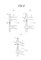
- the recess 6 is formed between each of the wall surfaces 61 and 62 forming the recess 6 in a plan view of the tread and a virtual extension line of the groove wall 21 of the circumferential groove extending in the tire circumferential direction.
- the inclination direction of the wall surface 62 forming the angle ⁇ 2 with respect to the circumferential groove 2 is preferably the same as the inclination direction of the protrusion 7 with respect to the circumferential groove 2.
- the protrusion 7 is located near the wall surface 62 that forms the angle ⁇ 2 between the recesses 6 adjacent in the tire circumferential direction, that is, in the circumferential groove 2. It is preferable to be formed at a position closer to the wall surface 62 than an intermediate point of the widthwise grooves 3 adjacent in the tire circumferential direction. As described with reference to FIG. 6B, when the recess 6 is provided, the point M where the wind in the circumferential groove 2 collides exists at a position close to the wall surface 62, so that heat radiation is promoted at this position. Hateful. Therefore, by forming the protrusion 7 at this position, it is possible to effectively dissipate heat from the tread portion.
- the widthwise groove 3 is inclined with respect to the tire width direction, and the groove wall 31 and the groove wall 32 of the widthwise groove 3 and the groove wall 22 of the circumferential groove 2 respectively. It is also possible to form the obtuse angle ⁇ 1 and the acute angle ⁇ 2 and arrange the wall surface 61 of the recess 6 forming the angle ⁇ 1 on the obtuse angle ⁇ 1 side, and arrange the wall surface 62 of the recess 6 forming the angle ⁇ 2 on the acute angle ⁇ 2 side. By adopting such a configuration, the air flow from the widthwise groove 3 becomes smooth, and more air can be introduced into the circumferential groove 2.
- the recess 6 may be a quadrangle as shown in FIG. 9A or a rounded shape as shown in FIG. 9B.
- the recess 6 has a rounded shape as shown in FIG. 9B, as shown in FIG. 9, the starting point of the recess 6 in the circumferential groove wall and the innermost part of the recess 6
- the above-mentioned angles ⁇ 1 and ⁇ 2 can be defined with the line segments connecting the two as the wall surfaces 61 and 62 of the recesses.
- the line connecting the connection point 6a and the connection point 6b defined in the shape of the recess 6 is the point A. Are parallel to the line connecting B and B and at least partially coincide.
- the recess 6 has an opening area as viewed from the tread tread surface 1 that gradually decreases from the tread tread surface 1 toward the groove bottom, that is, FIG.
- the wall surface 61 and the wall surface 62 of the recess 6 are preferably inclined toward the groove bottom.
- the opening area viewed from the tread tread 1 gradually decreases from the tread tread 1 toward the groove bottom, that is, FIG.
- the groove wall 21 and the groove wall 22 of the circumferential groove 2 are inclined toward the groove bottom, and FIG. 10 (d) shows D in FIG. 10 (a).
- the groove wall 31 and the groove wall 32 of the widthwise groove 3 are preferably inclined toward the groove bottom.
- the recess 6 in the plan view of the tread surface 1 preferably has a length L in the tire circumferential direction of 150 mm or less and a length W in the tire width direction of 50 mm or less. This is because if the recess 6 is too large, the wear performance may be deteriorated, and if it is too small, the effect of changing the dispersion of the wind in the circumferential groove 2 may not be sufficiently obtained.
- the recess 6 may be provided at least in a part of the groove wall from the tread surface 1 to the groove bottom, and is preferably provided at least in the groove bottom. However, as shown in FIG. Most preferably, the tread surface is provided.
- the temperature of the block land portion 5 is high on the groove bottom side, that is, on the side close to the carcass inside the tread, and decreases as the tread surface 1 is approached. Therefore, it is preferable to provide the recess 6 at the groove bottom because the direction of the wind in the circumferential groove 2 adjacent to the high temperature portion can be changed.
- the protrusion 7 is inclined at an angle ⁇ of less than 90 ° C. with respect to the circumferential groove 2 in the tread plan view, more specifically, with respect to the groove center line WL of the circumferential groove 2. It is preferable to stand vertically with respect to the groove bottom.
- the wind over the protruding portion 7 flows in a spiral (swirl shape) from the groove wall 21 side toward the groove wall 22 side as shown in FIG. It is possible to further improve the heat dissipation of the back side portion of the.
- the angle ⁇ formed by the protrusion 7 and the groove center line WL is 10 ° or more and 60 ° or less.
- the angle ⁇ is less than 10 °, the acute flow formed by the protrusion 7 and the groove wall 21 or the groove wall 22 makes the flow of wind flowing in the circumferential groove 2 extremely weak, and the heat dissipation from the tread portion is efficient. May not be possible.
- the angle ⁇ exceeds 60 °, the effect of changing the wind flowing in the circumferential groove 2 into a spiral flow becomes weak.
- the protrusion 7 is 0.75 ⁇ It is preferable that the relationship of L7 ⁇ P7 ⁇ 10 ⁇ L7 is satisfied. In the case of P7 ⁇ 0.75 ⁇ L7, the number of protrusions 7 formed in the circumferential groove 2 is excessively increased, the speed of the wind flowing in the circumferential groove 2 is greatly reduced, and the heat radiation from the tread portion is efficiently performed. May not be possible. On the other hand, when 10 ⁇ L7 ⁇ P7, the effect of changing the wind flowing in the circumferential groove 2 into a spiral flow is weakened.
- the length L7 is a length from one end to the other end of the protrusion 7 in the extending direction of the circumferential groove 2 (in the illustrated example, the tire circumferential direction).
- the interval P7 is the distance between the centers of the protrusions 7 where the protrusions 7 and the groove center line WL intersect.
- the protrusion 7 When the height of the protrusion 7 from the groove bottom 23 is H7 and the depth from the tread surface 1 of the circumferential groove 2 to the groove bottom 23 (deepest part) is D2, the protrusion 7 is 0.03 ⁇ It is preferable to satisfy the relationship of D2 ⁇ H7 ⁇ 0.4 ⁇ D2. In the case of H7 ⁇ 0.03 ⁇ D2, the height H7 of the protrusion 7 becomes too low, and the effect of changing the wind flowing in the circumferential groove 2 into a spiral flow becomes weak.
- the groove bottom 23 is preferably flat at a width of at least 0.2 ⁇ W2 across the groove center line WL, where the groove width of the circumferential groove 2 is W2.
- the central portion including the groove center line WL of the groove bottom 23 is not uneven, and the surface of the groove bottom 23 is flat, so that the flow of wind passing through the groove bottom 23 is not hindered, and heat dissipation from the tread portion is more efficient. Can be done automatically.
- FIG. 11A is a cross-sectional view taken along the line AA of FIG. 4, and FIGS. 11B to 11H are views showing modified examples of the protrusions.
- the upper end of the cross-sectional shape of the protrusion 7 may not be flat.
- the shape of the protrusion 7 is not limited to a flat plate shape having a substantially constant thickness W7 as shown in FIG. 4.
- the thickness W7 is substantially constant and extends in a wave shape.
- the wave shape and the vicinity of the groove center line WL are thicker and thinner toward the groove wall 21 and the groove wall 22, or the vicinity of the groove center line WL is thinner and closer to the groove wall 21 and the groove wall 22. It may be thicker.
- the groove width W2 of the circumferential groove 2 is preferably 3 mm or more and 50 mm or less because the air flow is hindered if it is too narrow, and if the groove width W2 is too wide, the joining of the protrusions and the width direction groove is not essential.
- the groove width of the width direction groove 3 is preferably 5 mm or more because air flow in the groove disappears if it is too narrow.
- Inventive tires 1 to 12 have the tread pattern shown in FIG. 1 except for the arrangement of the protrusions 7, and the comparative tires 1 to 5 have the same tread as the inventive tire 1 except for the presence or absence of the recess 6 and the protruding portion 7. Has a pattern.
- Table 1 shows the specifications of each test tire (tire size: 53 / 80R63).
- Each test tire was assembled to a rim (rim width: 36 inches) and an internal pressure (600 kPa) was applied, and then an indoor drum test (load: 82.5 tons, drum diameter: 5 m, drum surface speed: 8 km / h) Then, the temperature of the rib-shaped central land portion 4 adjacent to the circumferential groove 2 after running for 24 hours was measured.
- the measurement results are shown in Table 1.
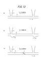
- the temperature measurement location is as shown in FIG.
- the merge point is a point on the rib-like central land portion 4 adjacent to the point where the circumferential groove 2 and the width direction groove 3 merge, and the circumferential half point is adjacent to the circumferential groove 2.
- Points on the rib-like central land portion 4 adjacent to the intermediate point of the widthwise groove 3 to be performed, and the circumferential direction 1/4 point and the circumferential direction 3/4 point are respectively a confluence and a circumferential direction 1/2 point. It is a point on the rib-shaped central land portion 4 adjacent to the intermediate point.
- the average temperature at the above four points of each tire is calculated, and the average temperature in the comparative tire 4 is set to 100, and the cooling effect of each tire is calculated. The index was evaluated. A larger value indicates a greater cooling effect.
Landscapes
- Engineering & Computer Science (AREA)
- Mechanical Engineering (AREA)
- Tires In General (AREA)
Description
従来、トレッド部の温度を低下させるには、トレッド部に溝を形成することで、発熱源となるトレッドゴムを除去するとともに、トレッド部の表面積を増加して放熱を高めるという方法が採用されてきた(例えば、特許文献1)。
それゆえ、本発明の目的は、溝の面積の増加を最小限に抑えて、トレッド部の放熱を促進し、トレッド部の温度を低下させた空気入りタイヤを提供することにある。
なお、上記の、幅方向溝に対向する周方向溝の溝壁に形成される凹部は、対応する幅方向溝の真向かいに形成されている。
本発明により、溝の面積の増加を最小限に抑えているため陸部剛性の低下を招くことなく、トレッド部の放熱を促進し、トレッド部の温度を低下させることができる。
この構成により、周方向溝の底部を流れる空気をかき乱し、同溝の底部と溝壁部との伝熱効率を高めることができる。
この構成により、凹部と突起部とが干渉せず、より多くの突起部を配置することができる。すなわち、周方向溝において、凹部を設けた側の溝壁はその対面の溝壁よりも周方向長さが凹部分短くなる。さらに、凹部が非対称形状で周方向溝に合流する幅方向溝の開口位置からずらして配置する。以上を総合したとき、周方向溝の底に設ける突起部は、角度θ2を形成する凹部の壁面と同じ向きに傾斜して設けることが、より多くの数を効率良く設置することにつながるのである。
この構成により、放熱が促進されにくい位置に突起部を配置することになるので、トレッド部からの放熱を効果的に行うことができる。
この構成により、幅方向溝からの空気の流れがスムーズになり、より多くの空気を周方向溝に導入することができる。
この構成により、凹部の石噛み性を改良することができる。
建設車両用タイヤは、ゴムボリュームが大きく、発熱の問題が特に顕著となりうるため、本発明の空気入りタイヤを建設車両用に用いると、特に効果的である。
図1は、建設車両用の空気入りタイヤのトレッドパターンの展開図である。トレッド踏面1には、タイヤ赤道面CLを挟んでタイヤ周方向に沿って延びる1対の周方向溝2と、これらの周方向溝2に開口し、周方向溝2より溝幅が広く、タイヤ幅方向に沿って延びる複数の幅方向溝3が形成されている。幅方向溝3は、トレッド端TEに連通している。
周方向溝2によって、タイヤ赤道面CLを含むリブ状中央陸部4が形成されている。周方向溝2と幅方向溝3とによって、ブロック状陸部5が形成されている。
なお、図示するトレッドパターンは一例であり、本発明は、リブ基調パターンおよびブロック基調パターンのいずれにも適用可能である。また、幅方向溝3は、タイヤ幅方向に対して傾斜してもよいし(好適な傾斜角度は、タイヤ幅方向に対して15~45°である)、その溝幅が一定ではなく変化してもよいし、トレッド端TEに連通していなくてもよい。また、周方向溝2は、直線状ではなく、ジグザグ状あるいは波状でもよい。
拡大図に示すように、凹部6は、タイヤ幅方向の長さWが、タイヤ周方向に沿って変化する。すなわち、凹部6と周方向溝2との接続点6aから凹部6の頂点6cに向かって長さWは漸増し、その後、頂点6cから凹部6と周方向溝2との接続点6bに向かって長さWは漸減する。
また、凹部6は、タイヤ周方向の長さLが、周方向溝2に開口する側から奥に向かって減少する。すなわち、長さLは、接続点6aと接続点6bとの間の距離が最大であり、頂点6cに向かうにつれて減少する。
図2(a)に示すように、凹部6を形成しない場合、幅方向溝3に対向する周方向溝2の溝壁とは、幅方向溝3の両溝壁を延長させて周方向溝2の溝壁と交わる点A、B間を表すものとする。
凹部6は、図2(b)に示すように、点A、B間に形成されてもよいし、図2(c)に示すように、点A、B間の外側にはみ出して形成されてもよい。また、図2(d)に示すように、周方向溝2と凹部6との接続点6bが、点A、B間に形成され、接続点6aが点A、B間の外側に形成されてもよい。すなわち、凹部6は、点A、B間に少なくとも一部が形成されていればよい。
凹部6は、図2(e)に示すように、周方向溝2と凹部6との接続点6aが、点A、B間の外側に形成され、接続点6bが点Bと一致して形成されていることが好ましい。
また、図2(f)に示すように、幅方向溝3が、タイヤ幅方向に対して傾斜している場合、幅方向溝3に対向する周方向溝2の溝壁とは、幅方向溝3の両溝壁を延長させて周方向溝2の溝壁と交わる点A、B間を表すものとする。そして、この点A、Bを基準として、上記の図2(b)~(e)に示したところと同様に、凹部6を配置すればよい。
なお、接続点6aと接続点6bを結んだ線は、点AとBを結んだ線と平行であり、かつ少なくとも部分的に一致する。
突起部7は、周方向溝2の一方の溝壁21から、この溝壁21に対向する他方の溝壁22まで延在している。すなわち、突起部7は、周方向溝2の溝幅W2全体にわたって形成されている。
突起部7は、周方向溝2の溝底23からタイヤ径方向外側に立設するように形成されている。突起部7は、例えば、平板状のゴムからなる。
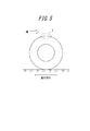
図5に示すように、タイヤが転動すると、タイヤの周囲には進行方向とは反対方向に風が流れる。この風を、トレッド踏面1に形成した溝に取り込み、この取り込んだ風を排出させることにより、トレッド部が放熱され、トレッド部の温度が低下する。特に、建設車両用の空気入りタイヤでは、図中Xで示すタイヤの車両側(接地面側と反対側)が車両に覆われず露出しているため、溝内に風を取り込むと放熱効果が顕著に現れる。
トレッド踏面1に形成した溝の溝幅を広くすると、溝内に多くの風を取り込むことはできるが、陸部剛性が低下して、摩耗性能や操縦安定性能が悪化する。それゆえ、既存の溝の溝幅を大きく変更させることなく、トレッド部の温度を低下させる方法が必要である。
タイヤの負荷転動によってブロック状陸部5の温度は上昇するが、ブロック状陸部5のうち、幅方向溝3に近い部分(図中斜線で示す)は、幅方向溝3内に流れる風によって放熱が行われ、温度が低下する。一方、ブロック状陸部5のうち、幅方向溝3から遠い部分は、放熱が行われない。幅方向溝3内には、図6(a)にて矢印で示すように、トレッド端TE(図1参照)から周方向溝2に向かって風が流れている。この風は、幅方向溝3に対向する周方向溝2の溝壁に衝突し、タイヤ回転方向に対して順方向と逆方向とに分散する。図示例のように、周方向溝2に対して幅方向溝3が垂直に形成されている場合、溝壁に衝突した風は、順方向と逆方向とに等しい風量で分散する。ある幅方向溝3から周方向溝2内に流れ込んだ順方向の風は、タイヤ周方向に隣接する幅方向溝3から周方向溝2内に流れ込んだ逆方向の風と、図6(a)に示した地点Mにおいて衝突する。すると、地点Mにおいて、風の流れが停滞するため、ブロック状陸部5の放熱が阻害されることになる。
なお、周方向溝2は、幅方向溝3より溝幅が狭いため、ブロック状陸部5のうち、周方向溝2に隣接した部分は、幅方向溝3に隣接した部分ほど放熱が行われない。
また、図6(c)に示すように、幅方向溝3をタイヤ幅方向に対して傾斜させるとともに凹部6を形成すると、幅方向溝3内から周方向溝2内に流れ込む風を、周方向溝2内においてより不均等に分散し、周方向溝2内の風がぶつかる地点Mを、幅方向溝3により近づけた位置に移動することができるので好ましい。
突起部7の背面側で滞留していた流体S2’は、主流S2に引っ張られて回転し、この部分の熱を奪って主流S2に合流する。同様に、次の突起部7のタイヤ回転方向に対する前側(前面側)で滞留していた流体S3’は、主流S3に引っ張られて回転し、この部分の熱を奪って主流S3に合流する。
このように、主流S1、S2、S3が突起部7を乗り越えて加速し、かつ、流体S2’、S3’が溝底23の熱を奪って主流S2、S3に合流することによって、広範囲でタイヤ温度を低減させることができる。
なお、説明のために、主流S1、S2、S3を断続して記載したが、実際には連続している。
図8(a)に示すように、凹部6は、トレッド平面視で凹部6を形成する壁面61、62のそれぞれと、タイヤ周方向に延びる周方向溝の溝壁21の仮想延長線との間の角度θ1、θ2について、θ1<θ2となる非対称な三角形とすることが好ましい。
この場合、角度θ2を形成する壁面62の、周方向溝2に対する傾斜方向は、突起部7の、周方向溝2に対する傾斜方向と同一であることが好ましい。このような構成にすることにより、上述したように、凹部6と突起部7とが干渉せず、より多くの突起部7を配置することができる。
図6(b)を用いて説明したように、凹部6を設けた場合、周方向溝2内の風がぶつかる地点Mは、壁面62に近い位置に存在するため、この位置は放熱が促進されにくい。それゆえ、この位置に突起部7を形成することにより、トレッド部からの放熱を効果的に行うことができる。
さらにまた、図8(c)に示すように、凹部6をθ1=θ2の2等辺三角形とすることもできるが、この場合、幅方向溝3に対してずらして形成する必要がある。すなわち、凹部6の頂点6cが、幅方向溝3の中心線(図中一点鎖線で示す)の上とは異なる位置に存在するように、凹部6を形成する必要がある。頂点6cを幅方向溝3の中心線上に配置すると、風を分散させることができず、トレッド部からの放熱を効果的に行うことができないためである。
このような構成にすることにより、幅方向溝3からの空気の流れがスムーズになり、より多くの空気を周方向溝2に導入することができる。
また、凹部6は、三角形の他、図9(a)に示すような四角形や、図9(b)に示すように丸みを持たせた形状とすることもできる。ここで、凹部6が図9(b)に示すような丸みを持たせた形状である場合は、同図に示すように、周方向溝壁の凹部6の起点と凹部6の最奥部とを結ぶ線分を凹部の壁面61および62として、上記した角度θ1およびθ2を規定することができる。
なお、凹部6が、図9(b)に示すような丸みを持たせた形状である場合にも、同凹部6の形状において定義した接続点6aと接続点6bを結んだ線は、点AとBを結んだ線と平行であり、かつ少なくとも部分的に一致する。
このような構成にすることにより、凹部6、周方向溝2および幅方向溝3の石噛み性を改良することができる。
ブロック状陸部5の温度は、溝底側、すなわち、トレッド内部のカーカスに近い側が高く、トレッド踏面1に近づくにつれて低下する。それゆえ、溝底に凹部6を設けることにより、温度が高い部分に隣接した周方向溝2内の風の向きを変えることができるため好ましい。
また、図4に示すように、突起部7と溝中心線WLとの成す角度θが10°以上60°以下であることがさらに好ましい。
角度θが10°未満の場合、突起部7と溝壁21または溝壁22とにより形成される鋭角部分によって周方向溝2内を流れる風の流れが極めて弱くなり、トレッド部からの放熱を効率的に行えないおそれがある。一方、角度θが60°超の場合、周方向溝2内を流れる風を螺旋状の流れに変化させる効果が弱くなる。
P7<0.75×L7の場合、周方向溝2に形成される突起部7の数が多くなり過ぎ、周方向溝2内を流れる風の速度が大きく低下し、トレッド部からの放熱を効率的に行えないおそれがある。一方、10×L7<P7の場合、周方向溝2内を流れる風を螺旋状の流れに変化させる効果が弱くなる。
なお、長さL7は、周方向溝2の延在方向(図示例では、タイヤ周方向)における突起部7の一端から他端までの長さである。間隔P7は、突起部7と溝中心線WLとが交差する突起部7の中心間の距離である。
H7≦0.03×D2の場合、突起部7の高さH7が低くなり過ぎ、周方向溝2内を流れる風を螺旋状の流れに変化させる効果が弱くなる。一方、0.4×D2<H7の場合、突起部7の高さH7が高くなり過ぎ、周方向溝2内を流れる風が溝底23に到達し難くなり、トレッド部からの放熱を効率的に行えないおそれがある。
さらに、突起部7の形状は、図4に示すような厚さW7が略一定の平板状に限定されることはなく、例えば、トレッド平面視において、厚さW7が略一定で波状に延在する波形状や、溝中心線WL付近が太く、溝壁21および溝壁22に向かうに連れて細くなる、または、溝中心線WL付近が細く、溝壁21および溝壁22に向かうに連れて太くなる形状でもよい。
幅方向溝3の溝幅は、狭すぎると溝内の空気流れがなくなる為に、5mm以上であることが好ましい。
発明例タイヤ1~12は、突起部7の配置以外は図1に示すトレッドパターンを有し、比較例タイヤ1~5は、凹部6および突起部7の有無以外は発明例タイヤ1と同じトレッドパターンを有している。各供試タイヤ(タイヤサイズ:53/80R63)の仕様を表1に示す。
各供試タイヤをリム(リム幅:36インチ)に組み付け、内圧(600kPa)を付与した後、室内ドラム試験(荷重:82.5トン、ドラム径:5m、ドラム表面速度:8km/h)にて、24時間走行後の周方向溝2に隣接するリブ状中央陸部4の温度を測定した。測定結果を、表1にあわせて示す。
温度の測定箇所は、図12(a)に示すとおりである。合流点とは、周方向溝2と幅方向溝3とが合流する地点に隣接するリブ状中央陸部4上の点であり、周方向1/2点とは、周方向溝2の、隣接する幅方向溝3の中間地点に隣接するリブ状中央陸部4上の点であり、周方向1/4点および周方向3/4点とは、それぞれ、合流点と周方向1/2点との中間地点に隣接するリブ状中央陸部4上の点である。
なお、比較例タイヤ4、5および発明例タイヤ8~12については、各タイヤの上記4つの点における温度の平均を算出し、比較例タイヤ4における平均温度を100として、各タイヤの冷却効果を指数評価した。数値が大きい方が、冷却効果が大きいことを示している。


発明例3、4は、発明例2と比較すると、突起部7の個数を増加することにより、少なくとも2点の温度がさらに低下していることがわかる。
発明例5は、発明例3と比較すると、突起部7を、角度θ2を形成する壁面62に近い位置に形成することにより、周方向3/4点の温度が低下していることがわかる。
さらに、比較例4、5と発明例8~12とを比較すると、三角形の凹部6の接続部6aおよび6bの相対位置と、突起部7の、周方向溝の溝中心線WLに対する傾斜角度との組み合せとが、凹部6および突起部7による冷却効果に影響していることがわかる。
2 周方向溝
3 幅方向溝
4 リブ状中央陸部
5 ブロック状陸部
6 凹部
7 突起部
21、22 溝壁
23 溝底
31、32 溝壁
61、62 壁面
Claims (7)
- トレッド踏面に、タイヤ周方向に沿って延びる少なくとも1本の周方向溝と、前記周方向溝に開口し、前記周方向溝より溝幅が広い、複数の幅方向溝が形成された空気入りタイヤであって、
前記幅方向溝に対向する前記周方向溝の溝壁に凹部が形成され、
タイヤ周方向に隣接する前記凹部間の、前記周方向溝の溝底には、少なくとも1つの突起部が形成されていることを特徴とする空気入りタイヤ。 - 前記凹部は、トレッド平面視で、前記凹部を形成する壁面と前記周方向溝の溝壁との角度θ1、θ2について、θ1<θ2となる非対称な形状であり、
前記突起部は、前記周方向溝の直交する方向に対して傾斜しており、
角度θ2を形成する前記凹部の前記壁面の、前記周方向溝に対する傾斜方向は、前記突起部の、前記周方向溝の溝壁に対する傾斜方向と同一であることを特徴とする請求項1に記載の空気入りタイヤ。 - 前記凹部は、トレッド平面視で、前記凹部を形成する壁面と前記周方向溝の溝壁との角度θ1、θ2について、θ1<θ2となる非対称な形状であり、
前記突起部は、タイヤ周方向に隣接する前記凹部間の、角度θ2を形成する前記凹部の前記壁面に近い位置に形成されていることを特徴とする請求項1または2に記載の空気入りタイヤ。 - 前記凹部は、トレッド平面視で、前記凹部を形成する壁面と前記周方向溝の溝壁との角度θ1、θ2について、θ1<θ2となる非対称な形状であり、
前記幅方向溝は、タイヤ幅方向に対して傾斜して、前記幅方向溝の溝壁と前記周方向溝の溝壁とにより鈍角および鋭角を形成し、
角度θ1を形成する前記凹部の壁面が前記鈍角側に配置され、角度θ2を形成する前記凹部の壁面が前記鋭角側に配置されていることを特徴とする請求項1~3のいずれかに記載の空気入りタイヤ。 - 前記凹部は、トレッド踏面から見た開口面積が、トレッド踏面から溝底に向かって漸減することを特徴とする請求項1~4のいずれかに記載の空気入りタイヤ。
- 前記突起部は、前記周方向溝の一方の溝壁から、前記一方の溝壁に対向する他方の溝壁まで延在していることを特徴とする請求項1~5のいずれかに記載の空気入りタイヤ。
- 建設車両用に用いられることを特徴とする請求項1~6のいずれかに記載の空気入りタイヤ。
Priority Applications (5)
| Application Number | Priority Date | Filing Date | Title |
|---|---|---|---|
| CA2871833A CA2871833C (en) | 2012-05-18 | 2013-05-17 | Pneumatic tire |
| EP13791434.7A EP2851211B1 (en) | 2012-05-18 | 2013-05-17 | Pneumatic tire |
| AU2013260938A AU2013260938B2 (en) | 2012-05-18 | 2013-05-17 | Pneumatic tyre |
| ES13791434.7T ES2621512T3 (es) | 2012-05-18 | 2013-05-17 | Rueda neumática |
| CN201380026098.1A CN104321208B (zh) | 2012-05-18 | 2013-05-17 | 充气轮胎 |
Applications Claiming Priority (2)
| Application Number | Priority Date | Filing Date | Title |
|---|---|---|---|
| JP2012114888A JP5557875B2 (ja) | 2012-05-18 | 2012-05-18 | 空気入りタイヤ |
| JP2012-114888 | 2012-05-18 |
Publications (1)
| Publication Number | Publication Date |
|---|---|
| WO2013172041A1 true WO2013172041A1 (ja) | 2013-11-21 |
Family
ID=49580315
Family Applications (1)
| Application Number | Title | Priority Date | Filing Date |
|---|---|---|---|
| PCT/JP2013/003157 Ceased WO2013172041A1 (ja) | 2012-05-18 | 2013-05-17 | 空気入りタイヤ |
Country Status (8)
| Country | Link |
|---|---|
| US (1) | US10688832B2 (ja) |
| EP (1) | EP2851211B1 (ja) |
| JP (1) | JP5557875B2 (ja) |
| CN (1) | CN104321208B (ja) |
| AU (1) | AU2013260938B2 (ja) |
| CA (1) | CA2871833C (ja) |
| ES (1) | ES2621512T3 (ja) |
| WO (1) | WO2013172041A1 (ja) |
Cited By (1)
| Publication number | Priority date | Publication date | Assignee | Title |
|---|---|---|---|---|
| US10688832B2 (en) | 2012-05-18 | 2020-06-23 | Bridgestone Corporation | Pneumatic tire |
Families Citing this family (9)
| Publication number | Priority date | Publication date | Assignee | Title |
|---|---|---|---|---|
| JP5636399B2 (ja) * | 2012-07-04 | 2014-12-03 | 株式会社ブリヂストン | タイヤ |
| JP5690407B2 (ja) | 2012-07-04 | 2015-03-25 | 株式会社ブリヂストン | タイヤ |
| JP5557943B1 (ja) * | 2013-04-09 | 2014-07-23 | 株式会社ブリヂストン | 空気入りタイヤ |
| JP5820442B2 (ja) * | 2013-08-23 | 2015-11-24 | 株式会社ブリヂストン | 空気入りタイヤ |
| JP6527758B2 (ja) * | 2015-06-13 | 2019-06-05 | 株式会社ブリヂストン | 空気入りタイヤ |
| JP7027873B2 (ja) * | 2017-12-20 | 2022-03-02 | 住友ゴム工業株式会社 | タイヤ |
| JP7116014B2 (ja) * | 2019-06-12 | 2022-08-09 | 株式会社ブリヂストン | 空気入りタイヤ |
| JP7156337B2 (ja) * | 2020-06-16 | 2022-10-19 | 住友ゴム工業株式会社 | タイヤ |
| CN115891512B (zh) * | 2022-11-29 | 2024-09-03 | 江苏通用科技股份有限公司 | 全钢子午线矿山轮胎花纹散热结构 |
Citations (6)
| Publication number | Priority date | Publication date | Assignee | Title |
|---|---|---|---|---|
| JPH07232514A (ja) * | 1993-12-27 | 1995-09-05 | Hirohisa Fukada | 車両用タイヤ |
| JP2002337514A (ja) * | 2001-05-22 | 2002-11-27 | Sumitomo Rubber Ind Ltd | 空気入りタイヤ |
| JP2003205706A (ja) | 2002-01-15 | 2003-07-22 | Bridgestone Corp | 空気入りタイヤ |
| JP2008221964A (ja) * | 2007-03-12 | 2008-09-25 | Bridgestone Corp | 空気入りタイヤ |
| JP2008302740A (ja) * | 2007-06-05 | 2008-12-18 | Bridgestone Corp | 空気入りタイヤ |
| JP2009137519A (ja) * | 2007-12-10 | 2009-06-25 | Bridgestone Corp | 空気入りタイヤ |
Family Cites Families (18)
| Publication number | Priority date | Publication date | Assignee | Title |
|---|---|---|---|---|
| AT398731B (de) * | 1990-04-25 | 1995-01-25 | Semperit Ag | Fahrzeugluftreifen |
| JPH0796716A (ja) * | 1993-09-29 | 1995-04-11 | Yokohama Rubber Co Ltd:The | 重荷重用空気入りタイヤ |
| JP3136101B2 (ja) * | 1996-09-19 | 2001-02-19 | 住友ゴム工業株式会社 | 空気入りタイヤ |
| JP3833785B2 (ja) * | 1997-07-15 | 2006-10-18 | 株式会社ブリヂストン | 空気入りタイヤ |
| JP3335118B2 (ja) * | 1998-01-19 | 2002-10-15 | 住友ゴム工業株式会社 | 重荷重用タイヤ |
| ES2323007T3 (es) * | 2000-01-26 | 2009-07-03 | Bridgestone Corporation | Neumatico. |
| JP2002240513A (ja) * | 2001-02-20 | 2002-08-28 | Bridgestone Corp | 空気入りタイヤ |
| EP1568514A4 (en) * | 2002-11-26 | 2010-12-29 | Yokohama Rubber Co Ltd | TIRE |
| US20040112492A1 (en) * | 2002-12-12 | 2004-06-17 | John Kotanides | Tire for inter-city buses and motor coaches |
| US7004216B2 (en) * | 2003-12-11 | 2006-02-28 | The Goodyear Tire & Rubber Company | Tire tread including spaced projections in base of groove |
| US6971426B1 (en) * | 2004-05-28 | 2005-12-06 | Amerityre | Elastomeric tire with arch shaped shoulders |
| JP5129470B2 (ja) | 2006-08-24 | 2013-01-30 | 住友ゴム工業株式会社 | 空気入りタイヤ |
| JP5165975B2 (ja) * | 2007-09-13 | 2013-03-21 | 株式会社ブリヂストン | 空気入りタイヤ |
| DE102008037497A1 (de) * | 2008-10-30 | 2010-05-06 | Continental Reifen Deutschland Gmbh | Fahrzeugluftreifen |
| JP5290707B2 (ja) * | 2008-11-10 | 2013-09-18 | 東洋ゴム工業株式会社 | 空気入りタイヤ |
| JP4685919B2 (ja) * | 2008-12-08 | 2011-05-18 | 住友ゴム工業株式会社 | 空気入りタイヤ |
| JP5557821B2 (ja) * | 2011-10-13 | 2014-07-23 | 株式会社ブリヂストン | 空気入りタイヤ |
| JP5557875B2 (ja) | 2012-05-18 | 2014-07-23 | 株式会社ブリヂストン | 空気入りタイヤ |
-
2012
- 2012-05-18 JP JP2012114888A patent/JP5557875B2/ja not_active Expired - Fee Related
-
2013
- 2013-05-17 AU AU2013260938A patent/AU2013260938B2/en not_active Ceased
- 2013-05-17 CA CA2871833A patent/CA2871833C/en active Active
- 2013-05-17 ES ES13791434.7T patent/ES2621512T3/es active Active
- 2013-05-17 CN CN201380026098.1A patent/CN104321208B/zh not_active Expired - Fee Related
- 2013-05-17 US US13/896,770 patent/US10688832B2/en active Active
- 2013-05-17 WO PCT/JP2013/003157 patent/WO2013172041A1/ja not_active Ceased
- 2013-05-17 EP EP13791434.7A patent/EP2851211B1/en not_active Not-in-force
Patent Citations (6)
| Publication number | Priority date | Publication date | Assignee | Title |
|---|---|---|---|---|
| JPH07232514A (ja) * | 1993-12-27 | 1995-09-05 | Hirohisa Fukada | 車両用タイヤ |
| JP2002337514A (ja) * | 2001-05-22 | 2002-11-27 | Sumitomo Rubber Ind Ltd | 空気入りタイヤ |
| JP2003205706A (ja) | 2002-01-15 | 2003-07-22 | Bridgestone Corp | 空気入りタイヤ |
| JP2008221964A (ja) * | 2007-03-12 | 2008-09-25 | Bridgestone Corp | 空気入りタイヤ |
| JP2008302740A (ja) * | 2007-06-05 | 2008-12-18 | Bridgestone Corp | 空気入りタイヤ |
| JP2009137519A (ja) * | 2007-12-10 | 2009-06-25 | Bridgestone Corp | 空気入りタイヤ |
Non-Patent Citations (1)
| Title |
|---|
| See also references of EP2851211A4 * |
Cited By (1)
| Publication number | Priority date | Publication date | Assignee | Title |
|---|---|---|---|---|
| US10688832B2 (en) | 2012-05-18 | 2020-06-23 | Bridgestone Corporation | Pneumatic tire |
Also Published As
| Publication number | Publication date |
|---|---|
| CN104321208A (zh) | 2015-01-28 |
| US10688832B2 (en) | 2020-06-23 |
| JP5557875B2 (ja) | 2014-07-23 |
| AU2013260938B2 (en) | 2015-05-21 |
| CA2871833A1 (en) | 2013-11-21 |
| EP2851211A1 (en) | 2015-03-25 |
| EP2851211A4 (en) | 2015-12-30 |
| CN104321208B (zh) | 2016-01-20 |
| CA2871833C (en) | 2015-12-22 |
| US20130306210A1 (en) | 2013-11-21 |
| JP2013241069A (ja) | 2013-12-05 |
| ES2621512T3 (es) | 2017-07-04 |
| AU2013260938A1 (en) | 2014-12-04 |
| EP2851211B1 (en) | 2017-01-18 |
Similar Documents
| Publication | Publication Date | Title |
|---|---|---|
| JP5557875B2 (ja) | 空気入りタイヤ | |
| CA2848908C (en) | Pneumatic tire | |
| JP5977696B2 (ja) | 空気入りタイヤ | |
| WO2014142349A1 (ja) | 空気入りタイヤ | |
| JP6844377B2 (ja) | タイヤ | |
| JP5568657B1 (ja) | 空気入りタイヤ | |
| WO2015025790A1 (ja) | 空気入りタイヤ | |
| WO2014142348A1 (ja) | 空気入りタイヤ | |
| JP5557821B2 (ja) | 空気入りタイヤ | |
| JP7116746B2 (ja) | 重荷重用タイヤ | |
| JP5557943B1 (ja) | 空気入りタイヤ | |
| JP2019104360A (ja) | 重荷重用タイヤ | |
| JP6060138B2 (ja) | 空気入りタイヤ | |
| JP6890086B2 (ja) | 重荷重用タイヤ | |
| JP6029957B2 (ja) | 空気入りタイヤ | |
| WO2019116626A1 (ja) | 重荷重用タイヤ | |
| JP2019104362A (ja) | 重荷重用タイヤ |
Legal Events
| Date | Code | Title | Description |
|---|---|---|---|
| 121 | Ep: the epo has been informed by wipo that ep was designated in this application |
Ref document number: 13791434 Country of ref document: EP Kind code of ref document: A1 |
|
| ENP | Entry into the national phase |
Ref document number: 2871833 Country of ref document: CA |
|
| NENP | Non-entry into the national phase |
Ref country code: DE |
|
| REEP | Request for entry into the european phase |
Ref document number: 2013791434 Country of ref document: EP |
|
| WWE | Wipo information: entry into national phase |
Ref document number: 2013791434 Country of ref document: EP |
|
| ENP | Entry into the national phase |
Ref document number: 2013260938 Country of ref document: AU Date of ref document: 20130517 Kind code of ref document: A |