WO2013174459A1 - Paraboloides schlaginstrument - Google Patents
Paraboloides schlaginstrument Download PDFInfo
- Publication number
- WO2013174459A1 WO2013174459A1 PCT/EP2012/075191 EP2012075191W WO2013174459A1 WO 2013174459 A1 WO2013174459 A1 WO 2013174459A1 EP 2012075191 W EP2012075191 W EP 2012075191W WO 2013174459 A1 WO2013174459 A1 WO 2013174459A1
- Authority
- WO
- WIPO (PCT)
- Prior art keywords
- percussion instrument
- sound
- instrument according
- paraboloid
- face
- Prior art date
- Legal status (The legal status is an assumption and is not a legal conclusion. Google has not performed a legal analysis and makes no representation as to the accuracy of the status listed.)
- Ceased
Links
Images




Classifications
-
- G—PHYSICS
- G10—MUSICAL INSTRUMENTS; ACOUSTICS
- G10D—STRINGED MUSICAL INSTRUMENTS; WIND MUSICAL INSTRUMENTS; ACCORDIONS OR CONCERTINAS; PERCUSSION MUSICAL INSTRUMENTS; AEOLIAN HARPS; SINGING-FLAME MUSICAL INSTRUMENTS; MUSICAL INSTRUMENTS NOT OTHERWISE PROVIDED FOR
- G10D13/00—Percussion musical instruments; Details or accessories therefor
- G10D13/01—General design of percussion musical instruments
- G10D13/02—Drums; Tambourines with drumheads
-
- G—PHYSICS
- G01—MEASURING; TESTING
- G01D—MEASURING NOT SPECIALLY ADAPTED FOR A SPECIFIC VARIABLE; ARRANGEMENTS FOR MEASURING TWO OR MORE VARIABLES NOT COVERED IN A SINGLE OTHER SUBCLASS; TARIFF METERING APPARATUS; MEASURING OR TESTING NOT OTHERWISE PROVIDED FOR
- G01D13/00—Component parts of indicators for measuring arrangements not specially adapted for a specific variable
- G01D13/02—Scales; Dials
-
- G—PHYSICS
- G10—MUSICAL INSTRUMENTS; ACOUSTICS
- G10D—STRINGED MUSICAL INSTRUMENTS; WIND MUSICAL INSTRUMENTS; ACCORDIONS OR CONCERTINAS; PERCUSSION MUSICAL INSTRUMENTS; AEOLIAN HARPS; SINGING-FLAME MUSICAL INSTRUMENTS; MUSICAL INSTRUMENTS NOT OTHERWISE PROVIDED FOR
- G10D13/00—Percussion musical instruments; Details or accessories therefor
- G10D13/10—Details of, or accessories for, percussion musical instruments
-
- Y—GENERAL TAGGING OF NEW TECHNOLOGICAL DEVELOPMENTS; GENERAL TAGGING OF CROSS-SECTIONAL TECHNOLOGIES SPANNING OVER SEVERAL SECTIONS OF THE IPC; TECHNICAL SUBJECTS COVERED BY FORMER USPC CROSS-REFERENCE ART COLLECTIONS [XRACs] AND DIGESTS
- Y10—TECHNICAL SUBJECTS COVERED BY FORMER USPC
- Y10T—TECHNICAL SUBJECTS COVERED BY FORMER US CLASSIFICATION
- Y10T29/00—Metal working
- Y10T29/49—Method of mechanical manufacture
- Y10T29/4957—Sound device making
- Y10T29/49574—Musical instrument or tuning fork making
Definitions
- the invention is directed to a percussion instrument in the simplest case, similar to the shape of a djembe, with one or more rigidly connected resonance bodies in the form of elliptical paraboloids ⁇ 1 ⁇ , which are at their focal points ⁇ F ⁇ to meet.
- the DE 102009008755 A1 is usually a drum in the form of a djembe with a fur surface equipped as a clubface.
- the sound box has a more or less kettle-like shape.
- the sound outlet usually has one funnel-shaped or hyperboloidal shape.
- Other drums have cylindrical To shape.
- the new drum is the particular shape of the resonator and also the sound outlet through an elliptical paraboloid specified.
- the playing surfaces can also be on both sides, like common with many other drums.
- the object of the invention is a percussion instrument create with an enhanced sound experience.
- An advantageous embodiment of the invention is in the claim 2 specified.
- Several of these paraboloids can now be used with different (or even the same) sizes. Common to all of them is their focal point ⁇ F ⁇ .
- the propagation of the sound waves is purposefully reflected by the paraboloidal design of the resonance bodies in such a way that they are at first in focus ⁇ F ⁇ punctiform bundle.
- This now punctiform sound source is now the common starting point in the focal point of the other paraboloids. From there, the sound is now also reflected in the other paraboloid.
- the playing surfaces ⁇ 2 ⁇ can appear on multiple pages, or on just one side of the resulting whole body ⁇ 1 ⁇ are located.
- a vote of the different proportions of the resonance body to each other is arbitrary. Preferably, however, variants that are in harmonic relationship to one another are to be used, since the resulting sound spaces also influence one another, which is also intended. This special shape makes a completely new sound possible.
- the sound boxes can be made of metal, for example, Ceramics, wood, stone, glass, composites, glass fiber reinforced plastic, Be made of acrylic or other suitable materials that the sound reflect and inhibit. Also, it is possible to have the resonance chambers from a block to work out coherent material.
- ⁇ 3 ⁇ their resonance body can also be at an arbitrary angle to the other. Examples of this embodiment can be seen in Figs. 3a and 3b and in Fig. 5 .
- the resulting sound can be directed in the direction of the audience or on an external sound recording device.
- At the faces ⁇ 2 ⁇ may be natural or artificial skins (skins, foils, membranes, etc.) or thin sheets of any suitable material (sheet metal, plastic, wood, etc.).
- the playing surfaces can be made to vibrate by hand, with mechanical aids or otherwise, and thus generate sound.
- a further embodiment of the invention is in claim 3 specified.
- the respective focal point can be added as auxiliary sound output devices in the form of small speakers ⁇ 4 ⁇ which play sounds or music. Due to the special shape of the drum, these tones can be modulated by hitting the playing surface (s) or dampening it, which creates a very special sound effect.
- FIG. 6 is an exemplary sectional view with a loudspeaker ⁇ 4 ⁇ as a source of sound at the focal point ⁇ F ⁇ given.
- small rattles, bells or oscillating parts in or near the focal point ⁇ F ⁇ because they can be strongly stimulated by the resulting concentrated sound node to resonate and therefore as a sound source like a speaker ⁇ 4 ⁇ serve.
- a further embodiment of the invention is that at the focal point a microphone ⁇ 5 ⁇ or another sound recording device placed in order to divert the sound waves arising there either mechanically (hose, tube) or electronically and, if appropriate, forward, for example, to an amplifier or an effect device.
- This variant is shown in FIG. 7 by way of example as a sectional view with a microphone.
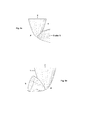
- this face can ⁇ 2 ⁇ also act around another, three-dimensional shape, which can be formed for example by means of deep-drawn plastic or sheet metal. These include, for example, but not limited to, wave patterns or concave / convex surfaces. Some examples are shown in Figs. 11a and 11b .
- FIG. 1 shows an angled variant with two paraboloids ⁇ 1 ⁇ , a face ⁇ 2 ⁇ and a sound outlet ⁇ 3 ⁇ with the common focus ⁇ F ⁇ .
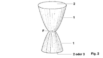
- FIG. 2 shows a variant with two paraboloids ⁇ 1 ⁇ in different sizes, a face ⁇ 2 ⁇ and a sound outlet ⁇ 3 ⁇ . This can also be used as another face ⁇ 2 ⁇ be formed.
- the common focus is with ⁇ F ⁇ .
- 3a and 3b shows two angled variants with two paraboloids ⁇ 1 ⁇ in different sizes, a face ⁇ 2 ⁇ and a sound outlet ⁇ 3 ⁇ . This can also be used as another face ⁇ 2 ⁇ be formed.
- the common focus is with ⁇ F ⁇ .
- FIG. 4 shows a variant with two paraboloids ⁇ 1 ⁇ in different sizes, a face ⁇ 2 ⁇ and a sound outlet ⁇ 3 ⁇ . This can also be used as another face ⁇ 2 ⁇ be formed.
- the common focus is with ⁇ F ⁇ .
- FIG. 5 shows a variant with two paraboloids ⁇ 1 ⁇ in different sizes, a face ⁇ 2 ⁇ and a sound outlet ⁇ 3 ⁇ . This can also be used as another face ⁇ 2 ⁇ be formed.
- the common focus is with ⁇ F ⁇ .
- FIG. 6 shows a section through a variant with two paraboloids ⁇ 1 ⁇ in different sizes, the common focus ⁇ F ⁇ and a sound source attached to it ⁇ 4 ⁇ .
- FIG. 7 shows a section through a variant with two paraboloids ⁇ 1 ⁇ in different sizes, the common focus ⁇ F ⁇ and a sound recording device attached thereto ⁇ 5 ⁇ .
- 9a to 9c shows several variants with four paraboloids ⁇ 1 ⁇ in different sizes, three playing surfaces ⁇ 2 ⁇ and a sound outlet ⁇ 3 ⁇ . This can also be used as another face ⁇ 2 ⁇ be formed.
- the common focus is with ⁇ F ⁇ .
- 10a to 10c shows several variants with two paraboloids ⁇ 1 ⁇ in different sizes, a face ⁇ 2 ⁇ and a sound outlet ⁇ 3 ⁇ . This can also be used as another face ⁇ 2 ⁇ be formed.
- the common focus is with ⁇ F ⁇ .
- FIGS. 11a and 11b show, by way of example, different curved surfaces, which are likewise used as the face ⁇ 2 ⁇ can be used.
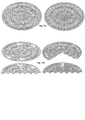
- FIG. 12a shows by way of example the individual rings of a possible method for producing a paraboloidal body according to claim 5. These are then assembled to form the final form shown Fig. 12b .
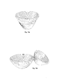
- Fig. 13b shows an example of a way to disassemble a suitable mold, and Fig. 13a as they can be put together to save space.
- a possible method for producing a percussion instrument according to one of the claims 1 to 3 suitable shapes are realized by producing rings of plate material having a diameter adapted to the paraboloid shape to be produced. After creating the rings, they are joined together to form the final shape. An illustration of this method is shown in Figs. 12a and 12b .
Landscapes
- Physics & Mathematics (AREA)
- Engineering & Computer Science (AREA)
- Acoustics & Sound (AREA)
- Multimedia (AREA)
- General Physics & Mathematics (AREA)
- Electrophonic Musical Instruments (AREA)
Description
- F Brennpunkt
- 1 Resonanzkörper
- 2 Schlagfläche
- 3 Schallaustritt
- 4 Lautsprecher, Schallquelle
- 5 Mikrofon
Claims (6)
- Paraboloides Schlaginstrument, mit mindestens einer Schlagfläche {
2 } und mehreren Resonanzkörpern,dadurch gekennzeichnet,dass die Resonanzkörper an ihrer Innenseite die räumliche Form elliptischer Paraboloiden {1 } beschreiben, welche sich in ihren jeweiligen Brennpunkten {F } räumlich treffen. - Schlaginstrument nach Patentanspruch
1, dadurch gekennzeichnet,dass die Paraboloiden {1 } verschiedene Größen aufweisen, wobei mehrere derart geformte Resonanzkörper vorgesehen sind. - Schlaginstrument nach Patentanspruch
1, dadurch gekennzeichnet,dass im jeweiligen Brennpunkt {F } zusätzlich Schallaufnahme- oder Schallabgabeeinrichtungen {5 ,4 } platziert sind. - Schlaginstrument nach Patentanspruch
1, dadurch gekennzeichnet,dass die mindestens eine Schlagfläche {2 } eine räumlich gekrümmte Fläche ist. - Verfahren zur Herstellung eines Schlaginstruments nach einem der Patentansprüche
1 bis 3, mit folgenden Schritten:- Erzeugung von Ringen aus Plattenmaterial mit an die herzustellende Paraboloidform angepasstem Durchmesser und- Zusammenfügen der Ringe zur Endform. - Schlaginstrument nach einem der Patentansprüche
1 bis 3 ,dadurch gekennzeichnet,dass die Resonanzkörper zerlegbar ausgebildet sind.
Priority Applications (9)
| Application Number | Priority Date | Filing Date | Title |
|---|---|---|---|
| CN201280073153.8A CN104285251B (zh) | 2012-05-20 | 2012-12-12 | 抛物面打击乐器 |
| HK15109677.4A HK1210314B (en) | 2012-05-20 | 2012-12-12 | Paraboloidal percussion instrument |
| ES12799192T ES2793400T3 (es) | 2012-05-20 | 2012-12-12 | Instrumento de percusión parabólico |
| MX2014013985A MX352833B (es) | 2012-05-20 | 2012-12-12 | Instrumento de percusión paraboloide. |
| US14/402,596 US9435671B2 (en) | 2012-05-20 | 2012-12-12 | Paraboloidal percussion instrument |
| EP12799192.5A EP2852949B1 (de) | 2012-05-20 | 2012-12-12 | Paraboloides schlaginstrument |
| RU2014146709A RU2619024C2 (ru) | 2012-05-20 | 2012-12-12 | Параболический ударный инструмент |
| CA2873444A CA2873444C (en) | 2012-05-20 | 2012-12-12 | Paraboloidal percussion instrument |
| IN10402DEN2014 IN2014DN10402A (de) | 2012-05-20 | 2014-12-05 |
Applications Claiming Priority (2)
| Application Number | Priority Date | Filing Date | Title |
|---|---|---|---|
| DE102012104332A DE102012104332B3 (de) | 2012-05-20 | 2012-05-20 | Paraboloides Schlaginstrument |
| DEDE102012104332 | 2012-05-20 |
Publications (1)
| Publication Number | Publication Date |
|---|---|
| WO2013174459A1 true WO2013174459A1 (de) | 2013-11-28 |
Family
ID=47351671
Family Applications (1)
| Application Number | Title | Priority Date | Filing Date |
|---|---|---|---|
| PCT/EP2012/075191 Ceased WO2013174459A1 (de) | 2012-05-20 | 2012-12-12 | Paraboloides schlaginstrument |
Country Status (10)
| Country | Link |
|---|---|
| US (1) | US9435671B2 (de) |
| EP (1) | EP2852949B1 (de) |
| CN (1) | CN104285251B (de) |
| CA (1) | CA2873444C (de) |
| DE (1) | DE102012104332B3 (de) |
| ES (1) | ES2793400T3 (de) |
| IN (1) | IN2014DN10402A (de) |
| MX (1) | MX352833B (de) |
| RU (1) | RU2619024C2 (de) |
| WO (1) | WO2013174459A1 (de) |
Families Citing this family (3)
| Publication number | Priority date | Publication date | Assignee | Title |
|---|---|---|---|---|
| US9711122B1 (en) * | 2015-10-08 | 2017-07-18 | Jason Van Pelt | Acoustic stomp box percussion device |
| US9633636B1 (en) | 2016-07-27 | 2017-04-25 | Martin Thomas Campitelli | Bass drum adaptor |
| CN106408805A (zh) * | 2016-11-02 | 2017-02-15 | 四川诚品电子商务有限公司 | 一种扩音法槌装置 |
Citations (5)
| Publication number | Priority date | Publication date | Assignee | Title |
|---|---|---|---|---|
| US4616551A (en) * | 1984-12-03 | 1986-10-14 | Steven Bookvich | Nada drum and assembly |
| US20060272475A1 (en) * | 2005-05-31 | 2006-12-07 | Claude Gauthier | Percussion instrument having membranes no facing each other |
| US7282633B1 (en) * | 2004-03-18 | 2007-10-16 | Coolidge Curtis J | Sound augmentation system and method for a drum |
| WO2009012503A1 (en) * | 2007-07-19 | 2009-01-22 | Nectar, Inc. | Portable drum |
| DE102009008755A1 (de) | 2009-02-12 | 2010-08-19 | Höcker, Martin | Trommel |
Family Cites Families (8)
| Publication number | Priority date | Publication date | Assignee | Title |
|---|---|---|---|---|
| US2858724A (en) * | 1958-06-09 | 1958-11-04 | Frederick J Troppe | Multiple-tone drum |
| US3818791A (en) * | 1973-07-02 | 1974-06-25 | W Zickos | Interchangeable drum resonators and generators |
| US4635524A (en) * | 1984-06-06 | 1987-01-13 | Allen Barbara A | Kettledrum |
| DE29608063U1 (de) * | 1996-05-04 | 1996-08-14 | Börmann, Ludger, 44145 Dortmund | Ringförmig aufgebautes Trommelgehäuse |
| DE29810574U1 (de) * | 1998-06-12 | 1998-09-03 | Kötting, Franz-Josef, 28844 Weyhe | Halb-Resonanz-Schlagzeug |
| US7781657B2 (en) * | 2005-01-15 | 2010-08-24 | Greg Nickel | Resonating chamber for devices including musical instruments |
| ITRM20080305A1 (it) * | 2008-06-11 | 2009-12-12 | Carlo Natali | Strumento musicale a percussione. |
| KR20110131400A (ko) * | 2010-05-31 | 2011-12-07 | (주)국림원 | 조립식 베개 겸용 장구 |
-
2012
- 2012-05-20 DE DE102012104332A patent/DE102012104332B3/de active Active
- 2012-12-12 CA CA2873444A patent/CA2873444C/en active Active
- 2012-12-12 CN CN201280073153.8A patent/CN104285251B/zh not_active Expired - Fee Related
- 2012-12-12 US US14/402,596 patent/US9435671B2/en active Active
- 2012-12-12 EP EP12799192.5A patent/EP2852949B1/de active Active
- 2012-12-12 WO PCT/EP2012/075191 patent/WO2013174459A1/de not_active Ceased
- 2012-12-12 RU RU2014146709A patent/RU2619024C2/ru active
- 2012-12-12 MX MX2014013985A patent/MX352833B/es active IP Right Grant
- 2012-12-12 ES ES12799192T patent/ES2793400T3/es active Active
-
2014
- 2014-12-05 IN IN10402DEN2014 patent/IN2014DN10402A/en unknown
Patent Citations (5)
| Publication number | Priority date | Publication date | Assignee | Title |
|---|---|---|---|---|
| US4616551A (en) * | 1984-12-03 | 1986-10-14 | Steven Bookvich | Nada drum and assembly |
| US7282633B1 (en) * | 2004-03-18 | 2007-10-16 | Coolidge Curtis J | Sound augmentation system and method for a drum |
| US20060272475A1 (en) * | 2005-05-31 | 2006-12-07 | Claude Gauthier | Percussion instrument having membranes no facing each other |
| WO2009012503A1 (en) * | 2007-07-19 | 2009-01-22 | Nectar, Inc. | Portable drum |
| DE102009008755A1 (de) | 2009-02-12 | 2010-08-19 | Höcker, Martin | Trommel |
Non-Patent Citations (3)
| Title |
|---|
| "About the Djembe Drum", 12 May 2012 (2012-05-12), pages 1 - 4, XP055058503, Retrieved from the Internet <URL:https://www.djembedirect.com/about/djembe.html#history> [retrieved on 20130404] * |
| "Hourglass Drum", 13 May 2011 (2011-05-13), pages 1, XP055058604, Retrieved from the Internet <URL:http://en.wikipedia.org/wiki/Hourglass_drum> [retrieved on 20130405] * |
| KASIN HUNTER: "Drums by Kasin Hunter", 15 June 2006 (2006-06-15), pages 1 - 5, XP055058609, Retrieved from the Internet <URL:http://kasinhunter.tripod.com/drums2001Row1.html> [retrieved on 20130405] * |
Also Published As
| Publication number | Publication date |
|---|---|
| ES2793400T3 (es) | 2020-11-13 |
| HK1210314A1 (en) | 2016-04-15 |
| DE102012104332B3 (de) | 2013-03-28 |
| CN104285251A (zh) | 2015-01-14 |
| CN104285251B (zh) | 2017-10-24 |
| US20150135932A1 (en) | 2015-05-21 |
| CA2873444A1 (en) | 2013-11-08 |
| RU2014146709A (ru) | 2016-07-10 |
| EP2852949A1 (de) | 2015-04-01 |
| MX2014013985A (es) | 2015-09-24 |
| US9435671B2 (en) | 2016-09-06 |
| EP2852949B1 (de) | 2020-02-26 |
| CA2873444C (en) | 2020-01-28 |
| IN2014DN10402A (de) | 2015-08-14 |
| RU2619024C2 (ru) | 2017-05-11 |
| MX352833B (es) | 2017-12-08 |
Similar Documents
| Publication | Publication Date | Title |
|---|---|---|
| DE3038939C2 (de) | ||
| DE112006000876T5 (de) | Elektroakustisches Hybridperkussionsinstrument | |
| DE102013107082B3 (de) | Schlag-, Blas- und Rasselinstrument und Musikinstrumentenanordnung | |
| DE102012104332B3 (de) | Paraboloides Schlaginstrument | |
| EP2792161A1 (de) | Lautsprechergehäuse | |
| HK1210314B (en) | Paraboloidal percussion instrument | |
| DE102009034110B3 (de) | Lautsprecherbox | |
| DE102011011115A1 (de) | Lautsprecheranordnung als Wellenfeldgenerator | |
| DE102012107991B3 (de) | Vorrichtung zum Erzeugen von Schallwellen in Wasser | |
| DE102010004533B4 (de) | Saitenführungsvorrichtung und Musikinstrument | |
| DE202016005361U1 (de) | Saiteninstrument, insbesondere E-Gitarre | |
| DE19506909A1 (de) | Vorrichtung zur Erzeugung von Tönen mit natürlichem Klangcharakter für elektronische Orgeln | |
| DE102017203184B4 (de) | Klangerzeugungsvorrichtung zur Erzeugung von Abgasanlagensound mit mehreren Ausgangsöffnungen sowie ein zugehöriges Kraftfahrzeug | |
| DE102012111717A1 (de) | Vorrichtung zum Halten einer Klangschale | |
| DE102012109001A1 (de) | Resonator-Schallabstrahlungsvorrichtung und Schallabstrahlungssystem | |
| DE202012104814U1 (de) | Resonanzboden für Klaviere mit Masseelement | |
| DE10357326A1 (de) | Musikinstrument | |
| DE202013007722U1 (de) | Klangerzeugendes Musikinstrument aus Beton | |
| Declercq et al. | The acoustics of the Hellenistic Theatre of Epidaurus: the important role of the seat rows | |
| DE102011122814A1 (de) | Schlaginstrument mit Lautsprecher und Bausatz zum Umbau einer Cajon in ein solches Schlaginstrument | |
| DE102008006448B4 (de) | Schlaginstrument, Verfahren zu dessen Herstellung | |
| DE1256261B (de) | Schwingplatte zur Erzeugung eines kuenstlichen Nachhalles | |
| DE202011001713U1 (de) | Lautsprechergehäuse mit einem Mitschwingungen verhindernden Aufbau | |
| EP1630311A2 (de) | Schallabsorbierende Vorrichtung, insbesondere zur Montage an einer Decke oder Wand | |
| DE202018103757U1 (de) | Schallabsorber |
Legal Events
| Date | Code | Title | Description |
|---|---|---|---|
| 121 | Ep: the epo has been informed by wipo that ep was designated in this application |
Ref document number: 12799192 Country of ref document: EP Kind code of ref document: A1 |
|
| ENP | Entry into the national phase |
Ref document number: 2873444 Country of ref document: CA |
|
| WWE | Wipo information: entry into national phase |
Ref document number: 2012799192 Country of ref document: EP |
|
| WWE | Wipo information: entry into national phase |
Ref document number: MX/A/2014/013985 Country of ref document: MX |
|
| WWE | Wipo information: entry into national phase |
Ref document number: 14402596 Country of ref document: US |
|
| WWE | Wipo information: entry into national phase |
Ref document number: IDP00201407825 Country of ref document: ID |
|
| ENP | Entry into the national phase |
Ref document number: 2014146709 Country of ref document: RU Kind code of ref document: A |