WO2013175720A1 - Connecteur - Google Patents
Connecteur Download PDFInfo
- Publication number
- WO2013175720A1 WO2013175720A1 PCT/JP2013/002999 JP2013002999W WO2013175720A1 WO 2013175720 A1 WO2013175720 A1 WO 2013175720A1 JP 2013002999 W JP2013002999 W JP 2013002999W WO 2013175720 A1 WO2013175720 A1 WO 2013175720A1
- Authority
- WO
- WIPO (PCT)
- Prior art keywords
- locking
- connector housing
- lock claw
- regulation wall
- rotation member
- Prior art date
- Legal status (The legal status is an assumption and is not a legal conclusion. Google has not performed a legal analysis and makes no representation as to the accuracy of the status listed.)
- Ceased
Links
Images





Classifications
-
- H—ELECTRICITY
- H01—ELECTRIC ELEMENTS
- H01R—ELECTRICALLY-CONDUCTIVE CONNECTIONS; STRUCTURAL ASSOCIATIONS OF A PLURALITY OF MUTUALLY-INSULATED ELECTRICAL CONNECTING ELEMENTS; COUPLING DEVICES; CURRENT COLLECTORS
- H01R13/00—Details of coupling devices of the kinds covered by groups H01R12/70 or H01R24/00 - H01R33/00
- H01R13/62—Means for facilitating engagement or disengagement of coupling parts or for holding them in engagement
- H01R13/625—Casing or ring with bayonet engagement
-
- H—ELECTRICITY
- H01—ELECTRIC ELEMENTS
- H01R—ELECTRICALLY-CONDUCTIVE CONNECTIONS; STRUCTURAL ASSOCIATIONS OF A PLURALITY OF MUTUALLY-INSULATED ELECTRICAL CONNECTING ELEMENTS; COUPLING DEVICES; CURRENT COLLECTORS
- H01R13/00—Details of coupling devices of the kinds covered by groups H01R12/70 or H01R24/00 - H01R33/00
- H01R13/62—Means for facilitating engagement or disengagement of coupling parts or for holding them in engagement
- H01R13/627—Snap or like fastening
-
- H—ELECTRICITY
- H01—ELECTRIC ELEMENTS
- H01R—ELECTRICALLY-CONDUCTIVE CONNECTIONS; STRUCTURAL ASSOCIATIONS OF A PLURALITY OF MUTUALLY-INSULATED ELECTRICAL CONNECTING ELEMENTS; COUPLING DEVICES; CURRENT COLLECTORS
- H01R13/00—Details of coupling devices of the kinds covered by groups H01R12/70 or H01R24/00 - H01R33/00
- H01R13/62—Means for facilitating engagement or disengagement of coupling parts or for holding them in engagement
- H01R13/627—Snap or like fastening
- H01R13/6271—Latching means integral with the housing
-
- H—ELECTRICITY
- H01—ELECTRIC ELEMENTS
- H01R—ELECTRICALLY-CONDUCTIVE CONNECTIONS; STRUCTURAL ASSOCIATIONS OF A PLURALITY OF MUTUALLY-INSULATED ELECTRICAL CONNECTING ELEMENTS; COUPLING DEVICES; CURRENT COLLECTORS
- H01R13/00—Details of coupling devices of the kinds covered by groups H01R12/70 or H01R24/00 - H01R33/00
- H01R13/62—Means for facilitating engagement or disengagement of coupling parts or for holding them in engagement
- H01R13/627—Snap or like fastening
- H01R13/6271—Latching means integral with the housing
- H01R13/6272—Latching means integral with the housing comprising a single latching arm
-
- H—ELECTRICITY
- H01—ELECTRIC ELEMENTS
- H01R—ELECTRICALLY-CONDUCTIVE CONNECTIONS; STRUCTURAL ASSOCIATIONS OF A PLURALITY OF MUTUALLY-INSULATED ELECTRICAL CONNECTING ELEMENTS; COUPLING DEVICES; CURRENT COLLECTORS
- H01R13/00—Details of coupling devices of the kinds covered by groups H01R12/70 or H01R24/00 - H01R33/00
- H01R13/62—Means for facilitating engagement or disengagement of coupling parts or for holding them in engagement
- H01R13/627—Snap or like fastening
- H01R13/6271—Latching means integral with the housing
- H01R13/6273—Latching means integral with the housing comprising two latching arms
-
- H—ELECTRICITY
- H01—ELECTRIC ELEMENTS
- H01R—ELECTRICALLY-CONDUCTIVE CONNECTIONS; STRUCTURAL ASSOCIATIONS OF A PLURALITY OF MUTUALLY-INSULATED ELECTRICAL CONNECTING ELEMENTS; COUPLING DEVICES; CURRENT COLLECTORS
- H01R13/00—Details of coupling devices of the kinds covered by groups H01R12/70 or H01R24/00 - H01R33/00
- H01R13/62—Means for facilitating engagement or disengagement of coupling parts or for holding them in engagement
- H01R13/627—Snap or like fastening
- H01R13/6275—Latching arms not integral with the housing
-
- H—ELECTRICITY
- H01—ELECTRIC ELEMENTS
- H01R—ELECTRICALLY-CONDUCTIVE CONNECTIONS; STRUCTURAL ASSOCIATIONS OF A PLURALITY OF MUTUALLY-INSULATED ELECTRICAL CONNECTING ELEMENTS; COUPLING DEVICES; CURRENT COLLECTORS
- H01R13/00—Details of coupling devices of the kinds covered by groups H01R12/70 or H01R24/00 - H01R33/00
- H01R13/62—Means for facilitating engagement or disengagement of coupling parts or for holding them in engagement
- H01R13/627—Snap or like fastening
- H01R13/6276—Snap or like fastening comprising one or more balls engaging in a hole or a groove
-
- H—ELECTRICITY
- H01—ELECTRIC ELEMENTS
- H01R—ELECTRICALLY-CONDUCTIVE CONNECTIONS; STRUCTURAL ASSOCIATIONS OF A PLURALITY OF MUTUALLY-INSULATED ELECTRICAL CONNECTING ELEMENTS; COUPLING DEVICES; CURRENT COLLECTORS
- H01R13/00—Details of coupling devices of the kinds covered by groups H01R12/70 or H01R24/00 - H01R33/00
- H01R13/62—Means for facilitating engagement or disengagement of coupling parts or for holding them in engagement
- H01R13/627—Snap or like fastening
- H01R13/6277—Snap or like fastening comprising annular latching means, e.g. ring snapping in an annular groove
Definitions
- the present invention relates to a connector having a bayonet structure to switch a locking state and an unlocking state between a pair of connectors with a weak operation force.
- a connector having a bayonet structure to switch a locking state and an unlocking state between a pair of connectors with a weak operation force is conventionally known (refer to PTL 1).
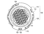
- a male connector 100 illustrated in Fig. 1 to Fig. 4 includes a male connector housing 110, and a bayonet ring (rotation member) 120 attached to the male connector housing 110 in a manner as to rotate between a locking start position and a locking end position of the connector.
- the male connector housing 110 is provided with a plurality of terminal chambers 111 therein to accommodate male terminals (not illustrated).
- the male connector housing 110 is provided, at a rear edge, with a first position regulation wall 112 and a second position regulation wall 113 each projecting outward.
- a first lock wall surface 112a and a second lock wall surface 112b are each vertically formed on both sides of the first position regulation wall 112.
- the bayonet ring 120 is provided with a plurality of cam projections 121 on the inner wall adjacent to a front edge of the bayonet ring 120.
- the cam projections 121 can engage with cam grooves 202 provided on a female connector housing 201 of a mating female connector 200.
- the bayonet ring 120 is provided, at the rear edge, with a locking arm 123 which can be deflected by a cantilever structure and provided with a lock claw 122, and an excessive rotation regulation projection 124.
- the lock claw 122 has a locking surface 122a that sequentially comes into contact with the second position regulation wall 113 and the first position regulation wall 112 of the male connector housing 110 when the bayonet ring 120 is rotated in an unlocking direction.
- the locking surface 122a is curved outward.
- the second position regulation wall 113 locks the lock claw 122 as illustrated in Fig. 4(a). Once the bayonet ring 120 is rotated in the unlocking direction, the second position regulation wall 113 comes into contact with the locking surface 122a of the lock claw 122, thereby deflecting the locking arm 123 as illustrated in Fig. 4(b). The second position regulation wall 113 is then allowed to pass over the lock claw 122.
- the male terminals are accommodated in the terminal chambers 111 of the male connector 100, and female terminals are accommodated in terminal chambers (not illustrated) of the mating female connector 200.
- the male connector housing 110 is set in the locking start position with respect to the female connector housing 201 in a manner as to position the cam projections 121 at entrances of the cam grooves 202, followed by rotating the bayonet ring 120 from the locking start position to the locking end position (namely, in a locking direction).
- the lock claw 122 then sequentially passes across the first position regulation wall 112 and the second position regulation wall 113 due to the deflection of the locking arm 123, so that the lock claw 122 moves to the locking end position.
- the second position regulation wall 113 regulates the rotation of the lock claw 122 so as to hold the lock claw 122.
- the male connector housing 110 and the female connector housing 201 move to the locking end position, and the cam projections 121 of the male connector housing 110 move along the cam grooves 202 of the female connector housing 201. Accordingly, the male connector 100 locks with the female connector 200, so that the male terminals are electrically connected to the female terminals.
- the lock claw 122 sequentially passes across the second position regulation wall 113 and the first position regulation wall 112 due to the deflection of the locking arm 123, and thereby moves to the locking start position.
- the male connector housing 110 and the female connector housing 201 shift to the locking start position.
- the first position regulation wall 112 regulates the rotation of the lock claw 122 so as to hold the lock claw 122.
- the connector according to the conventional example is desired to keep the bayonet ring 120 in the locking end position illustrated in Fig. 5 and Fig. 6 more stably because the connector is used under strong vibration condition and the like.
- the male connector 100 of the conventional example is provided with the locking surface 122a curved outward, which comes into contact with the second position regulation wall 113. Since the lock claw 122 is biased by reaction force applied to the locking surface 122a from the second position regulation wall 113, the lock claw 122 easily moves in the unlocking direction. Further, as illustrated in Figs. 4(a) and 4(b), the inclined angle I of the locking surface 122a to the moving direction of the second position regulation wall 113 in the state where the locking arm 123 is not deflected, is approximately equal to the inclined angle J of the locking surface 122a in the state where the locking arm 123 is deflected. This also allows the lock claw 122 to easily move in the unlocking direction. This easy movement limits the ability to keep the bayonet ring 120 in the locking end position.
- the increase of the inclined angle of the locking surface 122a may keep the bayonet ring 120 in the locking end position more stably. However, if the inclined angle of the locking surface 122a excessively increases; for example, if the inclined angle increases to a right angle, the possibility that the locking arm 123 is damaged increases.
- the present invention has been made in view of the above-described problem. It is an object of the present invention to provide a connector capable of preventing damage to a locking arm provided in a rotation member and keeping the rotation member in a locking end position more stably.
- a connector includes: a connector housing for accommodating one or more terminals; a rotation member attached to the connector housing in a manner as to be rotatable between a locking start position and a locking end position of the connector; a locking arm provided in the rotation member and including a lock claw having a locking surface, an unlocking direction side of the locking surface including a inclined surface linearly inclined to a base of the locking arm and a curved surface located at a top of the lock claw and formed in curved shape, the locking arm being deflectable; a first position regulation wall provided in the connector housing to lock the lock claw when the rotation member is located in the locking start position; and a second position regulation wall provided in the connector housing to lock the lock claw when the rotation member is located in the locking end position.
- the lock claw In the state where the connector housing is set in the locking start position with respect to a mating connector housing, the lock claw passes across the first position regulation wall and the second position regulation wall due to a deflection of the locking arm and moves to the locking end position when the rotation member is rotated from the locking start position to the locking end position, so that the connector housing and the mating connector housing move to the locking end position in association with the movement of the lock claw.
- the lock claw passes across the second position regulation wall and the first position regulation wall due to the deflection of the locking arm and moves to the locking start position when the rotation member is rotated from the locking end position to the locking start position, so that the connector housing and the mating connector housing move to the locking start position in association with the movement of the lock claw.
- a locking wall surface of the first position regulation wall that comes into contact with the locking arm when the rotation member is rotated from the locking end position to the locking start position is preferably formed in a tapered shape.
- the locking surface of the lock claw has the inclined surface that comes into contact with the second position regulation wall when the rotation member is rotated in the unlocking direction from the locking end position. Since the second position regulation wall presses the edge thereof into the locking surface, it is possible to keep the rotation member in the locking end position more stably without increasing a inclined angle of the locking surface. Further, due to the inclined surface provided in the locking surface, the inclined angle of the inclined surface changes to increasing with increasing of deflected level of the lock claw. This also contributes to keeping the rotation member in the locking end position more stably without increasing the inclined angle in the state in which the lock claw is not deflected.
- the curved surface at the top of the locking surface of the lock claw allows the second position regulation wall to smoothly pass over the lock claw, which provides a sense of completion of engagement. Once the second position regulation wall passes over the lock claw, the second position regulation wall surely makes a sound when the deflection of the lock claw is released and the lock claw thus returns to the initial position, which provides an operator with a stable unlocking operability of the connector.
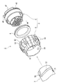
- Fig. 1 is an exploded perspective view of a male connector and a female connector in a conventional example.
- Fig. 2(a) is a front view of a male connector housing in the conventional example
- Fig. 2(b) is an enlarged front view of the part of G in Fig. 2(a).
- Fig. 3(a) is a front view of a rotation member in the conventional example
- Fig. 3(b) is an enlarged front view of the part of H in Fig. 3(a).
- Fig. 4(a) illustrates a state where a second position regulation wall of the male connector housing comes into contact with a lock claw of the rotation member in the conventional example
- FIG. 4(b) illustrates a state where a locking arm is deflected when the second position regulation wall of the male connector housing comes into contact with the lock claw of the rotation member in the conventional example.
- Fig. 5 illustrates the rear end of the male connector housing and the rotation member in the conventional example.
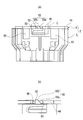
- Fig. 6(a) is a front view of the male connector housing and the rotation member in the conventional example, and Fig. 6(b) is an enlarged front view of the part of K in Fig. 6(a).
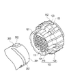
- Fig. 7 is an exploded perspective view of a connector device according to an embodiment.
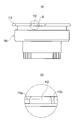
- Fig. 8(a) is a front view of a male connector housing according to the embodiment, and
- Fig. 8(b) is an enlarged front view of the part of A in Fig. 8(a).
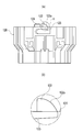
- Fig. 9(a) is a front view of a rotation member according to the embodiment
- Fig. 9(b) is an enlarged front view of the part of B in Fig. 9(a).
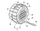
- Fig. 10 is a front perspective view of the male connector housing and the rotation member according to the embodiment.
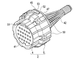
- Fig. 11 is a rear perspective view of the male connector housing and the rotation member according to the embodiment.
- Fig. 12 is a perspective view illustrating a state where a front holder is to be attached to the male connector housing according to the embodiment.
- Fig. 13 is a perspective view of a male connector completed as a final harness product according to the embodiment.
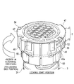
- Fig. 14 is a perspective view illustrating a state where the rotation member is located in a locking start position according to the embodiment.
- Fig. 10 is a front perspective view of the male connector housing and the rotation member according to the embodiment.
- Fig. 11 is a rear perspective view of the male connector housing and the rotation member according to the embodiment.
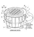
- FIG. 15 is a perspective view illustrating a state where the rotation member is located in a locking end position according to the embodiment.
- Fig. 16 illustrates the rear end of the male connector housing and the rotation member according to the embodiment.
- Fig. 17(a) is a front view of the male connector housing and the rotation member according to the embodiment, and Fig. 17(b) is an enlarged front view of the part of C in Fig. 17(a).
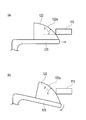
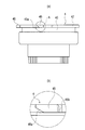
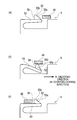
- Fig. 18(a) is an explanatory view of a locking arm and a lock claw of the rotation member,
- Fig. 18(b) is a view illustrating a state where a second position regulation wall of the male connector housing comes into contact with the lock claw of the rotation member, Fig.
- FIG. 18(c) is an enlarged view of the part of E in Fig. 18(b)
- Fig. 18(d) is a view illustrating a state where the locking arm is deflected when the second position regulation wall of the male connector housing comes into contact with the lock claw of the rotation member.
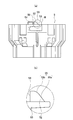
- Fig. 19(a) is an explanatory view of the lock claw of the rotation member and the second position regulation wall of the male connector housing
- Fig. 19(b) is a view illustrating a state where the lock claw is engaging with the second position regulation wall of the male connector housing
- Fig. 19(c) is a view illustrating a state where the engagement of the lock claw with the second position regulation wall is completed.
- Fig. 7 to Fig. 19 illustrate the embodiment of the present embodiment.
- a connector device 1 includes a male connector 2 serving as a connector according to the embodiment, and a female connector 3 serving as a mating connector.
- the male connector 2 includes a male connector housing 4, and a bayonet ring 5 that is a rotation member.
- the bayonet ring 5 is attached to the male connector housing 4 in a manner as to rotate between a locking start position and a locking end position of the connector.
- the locking start position of the connector is a position where the male connector 2 is unlocked with the female connector 3 via the bayonet ring 5.
- the locking end position of the connector is a position where the male connector 2 is locking with the female connector 3 via the bayonet ring 5.
- the male connector housing 4 accommodates a sealant 6.
- a front end of the female connector 3 comes into contact with the sealant 6 when the female connector 3 locks with the male connector 2.
- the sealant 6 seals a gap between the male connector 2 and the female connector 3.
- a front holder 41 is attached to a front end of the male connector housing 4.
- the inside of the male connector housing 4 is provided with a plurality of terminal chambers 44 each for accommodating a male terminal 43 crimped to a wire 42.
- a rear end of the male connector housing 4 is provided with a first position regulation wall 45 and a second position regulation wall 46 each laterally projecting to lock a lock claw 52 of a locking arm 53 provided on the bayonet ring 5.
- the rear end of the male connector housing 4 is provided with two excessive rotation regulation walls 47 each laterally projecting to come into contact with an excessive rotation regulation projection 54 of the bayonet ring 5.
- the first position regulation wall 45 locks the lock claw 52 when the male connector housing 4 and the bayonet ring 5 are placed in the locking start position. Then the bayonet ring 5 is located at the locking start position by the first position regulation wall 45. At this point, the bayonet ring 5 is positioned in a manner such that cam projections 51 of the bayonet ring 5 are located at entrances of cam grooves 32 of the female connector 3.
- the second position regulation wall 46 locks the lock claw 52 when the male connector housing 4 and the bayonet ring 5 are located in the locking end position. Then the bayonet ring 5 is located at the locking end position by the second position regulation wall 46.
- the first position regulation wall 45 includes a first locking wall surface 45a formed in tapered shape and a second locking wall surface 45b formed in vertical.
- the locking arm 53 comes into contact with the first locking wall surface 45a when the bayonet ring 5 is rotated from the locking end position to the locking start position (namely, in an unlocking direction).
- the locking arm 53 is gradually deflected along the tapered shape of the first locking wall surface 45a in association with the relative movement between the locking arm 53 and the first position regulation wall 45.
- the bayonet ring 5 is provided, adjacent to the front end of the outer wall, with rotation supporting projections 50 projecting inward and located at certain intervals in the circumferential direction.
- the rotation supporting projections 50 enter a circumferential groove 40 provided on the periphery of the male connector housing 4.
- the bayonet ring 5 is rotatably supported by the male connector housing 4 in a manner such that the rotation supporting projections 50 slide along the circumferential groove 40.
- the cam projections 51 are provided on the front of the inner wall of the bayonet ring 5.
- the cam projections 51 engage with the cam grooves 32 provided on a female connector housing 31 of the female connector 3.
- the rear end of the bayonet ring 5 is provided with the locking arm 53 which can be deflected by a cantilever structure and including the lock claw 52, and the excessive rotation regulation projection 54.
- the lock claw 52 includes a first locking surface 55 and a second locking surface 56 that come into contact with the first position regulation wall 45 and the second position regulation wall 46.
- the first locking surface 55 comes into contact with the first position regulation wall 45 and the second position regulation wall 46 when the bayonet ring 5 rotates in the unlocking direction from the locking end position.
- the first locking surface 55 includes an inclined surface 55a linearly formed at a base side, and a curved surface 55b integrated with the inclined surface 55a and located adjacent to the top of the first locking surface 55.
- the second locking surface 56 comes into contact with the first position regulation wall 45 and the second position regulation wall 46 when the bayonet ring 5 rotates from the locking start position to the locking end position (namely, in a locking direction).
- the second locking surface 56 is elongated vertically.
- the female connector housing 31 of the female connector 3 is also provided with a plurality of terminal chambers (not illustrated) each for housing a female terminal (not illustrated).
- the terminal chambers 44 of the male connector 2 accommodate the male terminals 43, and the terminal chambers of the female connector 3 accommodate the female terminals.
- the male connector housing 4 is set in the locking start position with respect to the female connector housing 31 in a manner such that the cam projections 51 are positioned at the entrances of the cam grooves 32.
- the bayonet ring 5 rotates from the locking start position to the locking end position (in the clockwise direction indicated by the arrow in Fig. 14, namely, in the locking direction).
- the lock claw 52 sequentially passes across the first position regulation wall 45 and the second position regulation wall 46 due to the deflection of the locking arm 53, and the lock claw 52 thus moves to the locking end position.
- the second position regulation wall 46 prevents the rotation of the lock claw 52 so as to hold the lock claw 52.
- the male connector housing 4 and the female connector housing 31 move to the locking end position in association with the movement of the lock claw 52.
- the cam projections 51 of the male connector housing 4 move along the cam grooves 32 of the female connector housing 31.
- the male connector 2 locks with the female connector 3, and the male terminals 43 are thus electrically connected to the female terminals.
- the lock claw 52 engages with the second position regulation wall 46 as illustrated in Fig. 19(a), the lock claw 52 then passes across the first position regulation wall 46 due to the deflection of the locking arm 53 as illustrated in Fig. 19(b), and passes through the second position regulation wall 46 as illustrated in Fig. 19(c).
- the lock claw 52 further passes across the first position regulation wall 45, and thereby moves to the locking start position.
- the male connector housing 4 and the female connector housing 31 move to the locking start position.
- the first position regulation wall 45 prevents the rotation of the lock claw 52 of the locking arm 53 so as to hold the lock claw 52.
- the inclined surface 55a located at the base side of the lock claw 52 comes into contact with the second position regulation wall 46 as illustrated in Fig. 18(b). Since the inclined surface 55a is formed linearly, an edge 46a of the second position regulation wall 46 bites the inclined surface 55a of the lock claw 52 as illustrated in Fig. 18(c). Thus, it is possible to keep the bayonet ring 5 in the locking end position more stably without increasing the inclined angle of the inclined surface 55a.
- the inclined angle of the inclined surface 55a changes to increasing with increasing of deflected level of the lock claw 52. That is, as illustrated in Figs. 18(b) and 18(d), an inclined angle F of the inclined surface 55a to the moving direction of the second position regulation wall 46 in the state where the locking arm 53 is deflected, is larger than an inclined angle D of the inclined surface 55a in the state where the locking arm 53 is not deflected.
- Such a configuration keeps the bayonet ring 5 in the locking end position more stably without increasing the inclined angle in the state in which the lock claw 52 is not deflected.
- the curved surface 55b is located at the top of the locking surface 55 of the lock claw 52.
- the second position regulation wall 46 thus can smoothly pass over the lock claw 52 as illustrated in Fig. 19(b), which provides a sense of completion of engagement. Further, once the second position regulation wall 46 passes over the lock claw 52, the second position regulation wall 46 surely makes a sound when the deflection of the lock claw 52 is released and the lock claw 52 thus returns to the initial position as illustrated in Fig. 19(c), which provides the operator with a stable unlocking operability of the connector.
- the bayonet ring 5 can easily rotates in a manner such that the locking arm 53 is gradually deflected as the inclined surface 55a of the lock claw 52 moves along the tapered first locking wall surface 45a, when the locking arm 53 located in the position between the first position regulation wall 45 and the second position regulation wall 46 moves to return to the locking start position. Accordingly, the bayonet ring 5 can be rotated smoothly compared to the case where the locking wall surface of the first position regulation wall is vertically formed as in the case of the conventional example (PTL1: US 6811423 B2).
- the locking surface of the lock claw 52 can be made fundamentally in a manner such that the curved surface indicated by the two-dot chain line illustrated in Fig. 18(a) (the locking surface of the lock claw of the conventional example) is changed to the inclined surface 55a indicated by the solid line illustrated in Fig. 18(a).
- the embodiment can be realized by slight changes of conventional dies.
- a spring constant of the locking arm 53 may be possibly increased in order to keep the bayonet ring 5 more stably.
- such a case may require great changes of the conventional dies. Therefore, changing the shape of the locking surface of the lock claw 52 as in the case of the embodiment may be an inexpensive way compared to increasing the spring constant of the locking arm of the conventional example.
- the locking surface 55 of the lock claw 52 also can be formed in a manner such that the locking surface of the lock claw of the conventional example indicated by the two-dot chain line illustrated in Fig. 18(a), is cut along the inclined surface 55a indicated by the solid line in Fig. 18(a). Since only simple process may be needed for the conventional example, the conventional example can be effectively utilized.
- the embodiment exemplifies the case where the bayonet ring 5 that is the rotation member is attached to the male connector housing 4.
- the embodiment is not limited to this case, and the bayonet ring may be attached to the female connector housing.
- the present invention provides a connector capable of preventing damage to a locking arm provided in a rotation member and keeping the rotation member in a locking end position of the connector more stably.
Landscapes
- Details Of Connecting Devices For Male And Female Coupling (AREA)
Priority Applications (2)
| Application Number | Priority Date | Filing Date | Title |
|---|---|---|---|
| CN201380026877.1A CN104335429B (zh) | 2012-05-23 | 2013-05-10 | 连接器 |
| KR1020147035633A KR101665468B1 (ko) | 2012-05-23 | 2013-05-10 | 커넥터 |
Applications Claiming Priority (2)
| Application Number | Priority Date | Filing Date | Title |
|---|---|---|---|
| JP2012117495A JP5886684B2 (ja) | 2012-05-23 | 2012-05-23 | コネクタ |
| JP2012-117495 | 2012-05-23 |
Publications (1)
| Publication Number | Publication Date |
|---|---|
| WO2013175720A1 true WO2013175720A1 (fr) | 2013-11-28 |
Family
ID=48670034
Family Applications (1)
| Application Number | Title | Priority Date | Filing Date |
|---|---|---|---|
| PCT/JP2013/002999 Ceased WO2013175720A1 (fr) | 2012-05-23 | 2013-05-10 | Connecteur |
Country Status (4)
| Country | Link |
|---|---|
| JP (1) | JP5886684B2 (fr) |
| KR (1) | KR101665468B1 (fr) |
| CN (1) | CN104335429B (fr) |
| WO (1) | WO2013175720A1 (fr) |
Cited By (2)
| Publication number | Priority date | Publication date | Assignee | Title |
|---|---|---|---|---|
| US11374351B2 (en) | 2018-04-06 | 2022-06-28 | Fischer Connectors Holding S.A. | Multipolar connector |
| US11616324B2 (en) | 2018-04-06 | 2023-03-28 | Conextivity Group Sa | Multipolar connector |
Families Citing this family (2)
| Publication number | Priority date | Publication date | Assignee | Title |
|---|---|---|---|---|
| US9726831B2 (en) * | 2015-07-02 | 2017-08-08 | Senko Advanced Components, Inc. | Bayonet lock MPO connector |
| JP2023041136A (ja) | 2021-09-13 | 2023-03-24 | 矢崎総業株式会社 | コネクタ |
Citations (3)
| Publication number | Priority date | Publication date | Assignee | Title |
|---|---|---|---|---|
| US6811423B2 (en) | 2001-11-26 | 2004-11-02 | Yazaki Corporation | Electrical connector assembly having a mechanism for ascertaining engaged condition |
| US20060240698A1 (en) * | 2005-04-25 | 2006-10-26 | Yazaki Corporation | Electrical connector |
| GB2431526A (en) * | 2005-10-20 | 2007-04-25 | Souriau | Threaded connector having anti-rotation locking means |
Family Cites Families (2)
| Publication number | Priority date | Publication date | Assignee | Title |
|---|---|---|---|---|
| JPS5953780U (ja) * | 1982-09-30 | 1984-04-09 | ソニー株式会社 | ケ−ブルコネクタのロツク機構 |
| JP4247542B2 (ja) * | 2004-08-30 | 2009-04-02 | ヒロセ電機株式会社 | 多極コネクタ |
-
2012
- 2012-05-23 JP JP2012117495A patent/JP5886684B2/ja active Active
-
2013
- 2013-05-10 KR KR1020147035633A patent/KR101665468B1/ko active Active
- 2013-05-10 CN CN201380026877.1A patent/CN104335429B/zh active Active
- 2013-05-10 WO PCT/JP2013/002999 patent/WO2013175720A1/fr not_active Ceased
Patent Citations (3)
| Publication number | Priority date | Publication date | Assignee | Title |
|---|---|---|---|---|
| US6811423B2 (en) | 2001-11-26 | 2004-11-02 | Yazaki Corporation | Electrical connector assembly having a mechanism for ascertaining engaged condition |
| US20060240698A1 (en) * | 2005-04-25 | 2006-10-26 | Yazaki Corporation | Electrical connector |
| GB2431526A (en) * | 2005-10-20 | 2007-04-25 | Souriau | Threaded connector having anti-rotation locking means |
Cited By (3)
| Publication number | Priority date | Publication date | Assignee | Title |
|---|---|---|---|---|
| US11374351B2 (en) | 2018-04-06 | 2022-06-28 | Fischer Connectors Holding S.A. | Multipolar connector |
| US11616324B2 (en) | 2018-04-06 | 2023-03-28 | Conextivity Group Sa | Multipolar connector |
| US11616320B2 (en) | 2018-04-06 | 2023-03-28 | Conextivity Group Sa | Multipolar connector |
Also Published As
| Publication number | Publication date |
|---|---|
| JP2013246884A (ja) | 2013-12-09 |
| CN104335429A (zh) | 2015-02-04 |
| KR101665468B1 (ko) | 2016-10-12 |
| CN104335429B (zh) | 2016-10-26 |
| KR20150011005A (ko) | 2015-01-29 |
| JP5886684B2 (ja) | 2016-03-16 |
Similar Documents
| Publication | Publication Date | Title |
|---|---|---|
| US7300294B2 (en) | Connector and connector assembly of the movable member type | |
| US9203186B2 (en) | Lever-type connector, wire cover | |
| EP1830436B1 (fr) | Connecteur, assemblage de connecteur et procédé d'assemblage | |
| JP2002352903A (ja) | レバー式コネクタ | |
| US20140206222A1 (en) | Lever-type connector | |
| US20060281350A1 (en) | Lever Type Connector | |
| US7445475B2 (en) | Lever type connector | |
| US6767231B1 (en) | Electrical connector with flexible blocking feature | |
| JP2011124057A (ja) | レバー式コネクタ | |
| JP2009110733A (ja) | コネクタ | |
| WO2013175720A1 (fr) | Connecteur | |
| JP2018120728A (ja) | レバー式コネクタ | |
| JP4497038B2 (ja) | レバー式コネクタ | |
| CN111525339B9 (zh) | 杆式连接器 | |
| JP2008027787A (ja) | レバー式コネクタ | |
| JP6902209B2 (ja) | レバー式コネクタ | |
| US20110217865A1 (en) | Electrical Connector Assembly | |
| JP4556134B2 (ja) | コネクタ | |
| JP4830920B2 (ja) | レバー式コネクタ | |
| EP1995828B1 (fr) | Connecteur de type levier et son procédé d'assemblage | |
| US9196993B2 (en) | Connector unit | |
| JP2022527722A (ja) | コネクタ位置保証部材 | |
| JP2009181719A (ja) | コネクタ | |
| JP2004349075A (ja) | コネクタ | |
| JP2009272046A (ja) | レバー式コネクタ |
Legal Events
| Date | Code | Title | Description |
|---|---|---|---|
| 121 | Ep: the epo has been informed by wipo that ep was designated in this application |
Ref document number: 13730368 Country of ref document: EP Kind code of ref document: A1 |
|
| NENP | Non-entry into the national phase |
Ref country code: DE |
|
| ENP | Entry into the national phase |
Ref document number: 20147035633 Country of ref document: KR Kind code of ref document: A |
|
| 122 | Ep: pct application non-entry in european phase |
Ref document number: 13730368 Country of ref document: EP Kind code of ref document: A1 |