WO2013176046A1 - Dispositif de traitement de signaux ultrasonores et procédé de traitement de signaux ultrasonores - Google Patents
Dispositif de traitement de signaux ultrasonores et procédé de traitement de signaux ultrasonores Download PDFInfo
- Publication number
- WO2013176046A1 WO2013176046A1 PCT/JP2013/063761 JP2013063761W WO2013176046A1 WO 2013176046 A1 WO2013176046 A1 WO 2013176046A1 JP 2013063761 W JP2013063761 W JP 2013063761W WO 2013176046 A1 WO2013176046 A1 WO 2013176046A1
- Authority
- WO
- WIPO (PCT)
- Prior art keywords
- element data
- stored
- ultrasonic
- signal processing
- depth
- Prior art date
- Legal status (The legal status is an assumption and is not a legal conclusion. Google has not performed a legal analysis and makes no representation as to the accuracy of the status listed.)
- Ceased
Links
Images


Classifications
-
- A—HUMAN NECESSITIES
- A61—MEDICAL OR VETERINARY SCIENCE; HYGIENE
- A61B—DIAGNOSIS; SURGERY; IDENTIFICATION
- A61B8/00—Diagnosis using ultrasonic, sonic or infrasonic waves
- A61B8/52—Devices using data or image processing specially adapted for diagnosis using ultrasonic, sonic or infrasonic waves
- A61B8/5207—Devices using data or image processing specially adapted for diagnosis using ultrasonic, sonic or infrasonic waves involving processing of raw data to produce diagnostic data, e.g. for generating an image
-
- A—HUMAN NECESSITIES
- A61—MEDICAL OR VETERINARY SCIENCE; HYGIENE
- A61B—DIAGNOSIS; SURGERY; IDENTIFICATION
- A61B8/00—Diagnosis using ultrasonic, sonic or infrasonic waves
- A61B8/44—Constructional features of the ultrasonic, sonic or infrasonic diagnostic device
- A61B8/4444—Constructional features of the ultrasonic, sonic or infrasonic diagnostic device related to the probe
-
- A—HUMAN NECESSITIES
- A61—MEDICAL OR VETERINARY SCIENCE; HYGIENE
- A61B—DIAGNOSIS; SURGERY; IDENTIFICATION
- A61B8/00—Diagnosis using ultrasonic, sonic or infrasonic waves
- A61B8/44—Constructional features of the ultrasonic, sonic or infrasonic diagnostic device
- A61B8/4483—Constructional features of the ultrasonic, sonic or infrasonic diagnostic device characterised by features of the ultrasound transducer
- A61B8/4494—Constructional features of the ultrasonic, sonic or infrasonic diagnostic device characterised by features of the ultrasound transducer characterised by the arrangement of the transducer elements
-
- G—PHYSICS
- G01—MEASURING; TESTING
- G01S—RADIO DIRECTION-FINDING; RADIO NAVIGATION; DETERMINING DISTANCE OR VELOCITY BY USE OF RADIO WAVES; LOCATING OR PRESENCE-DETECTING BY USE OF THE REFLECTION OR RERADIATION OF RADIO WAVES; ANALOGOUS ARRANGEMENTS USING OTHER WAVES
- G01S7/00—Details of systems according to groups G01S13/00, G01S15/00, G01S17/00
- G01S7/52—Details of systems according to groups G01S13/00, G01S15/00, G01S17/00 of systems according to group G01S15/00
- G01S7/52017—Details of systems according to groups G01S13/00, G01S15/00, G01S17/00 of systems according to group G01S15/00 particularly adapted to short-range imaging
- G01S7/52046—Techniques for image enhancement involving transmitter or receiver
- G01S7/52049—Techniques for image enhancement involving transmitter or receiver using correction of medium-induced phase aberration
-
- A—HUMAN NECESSITIES
- A61—MEDICAL OR VETERINARY SCIENCE; HYGIENE
- A61B—DIAGNOSIS; SURGERY; IDENTIFICATION
- A61B8/00—Diagnosis using ultrasonic, sonic or infrasonic waves
- A61B8/06—Measuring blood flow
-
- A—HUMAN NECESSITIES
- A61—MEDICAL OR VETERINARY SCIENCE; HYGIENE
- A61B—DIAGNOSIS; SURGERY; IDENTIFICATION
- A61B8/00—Diagnosis using ultrasonic, sonic or infrasonic waves
- A61B8/08—Clinical applications
-
- A—HUMAN NECESSITIES
- A61—MEDICAL OR VETERINARY SCIENCE; HYGIENE
- A61B—DIAGNOSIS; SURGERY; IDENTIFICATION
- A61B8/00—Diagnosis using ultrasonic, sonic or infrasonic waves
- A61B8/08—Clinical applications
- A61B8/0891—Clinical applications for diagnosis of blood vessels
-
- A—HUMAN NECESSITIES
- A61—MEDICAL OR VETERINARY SCIENCE; HYGIENE
- A61B—DIAGNOSIS; SURGERY; IDENTIFICATION
- A61B8/00—Diagnosis using ultrasonic, sonic or infrasonic waves
- A61B8/48—Diagnostic techniques
- A61B8/485—Diagnostic techniques involving measuring strain or elastic properties
Definitions
- the present invention relates to an ultrasonic signal processing apparatus and an ultrasonic signal processing method, and more particularly to an ultrasonic signal processing apparatus and an ultrasonic signal processing method for receiving an ultrasonic echo reflected by a subject and recording an ultrasonic signal.
- Patent Document 3 discloses that when the signal added by the ultrasonic transmission / reception unit 14 is stored as RF data (raw data), the resolution is changed between the designated area and other areas (paragraph [0015]. And [0020]).
- the raw data described in Patent Documents 1 and 2 are digital received signals obtained by A / D conversion after detecting the received signals from the probe.
- the raw data described in Patent Document 3 is RF data after addition processing.
- the raw data described in Non-Patent Document 1 is raw data after beam forming, that is, after phase matching addition. Therefore, the techniques described in Patent Documents 1 to 3 and Non-Patent Document 1 have a problem that element data useful for correcting the sound speed in the subject and creating a sound speed map cannot be stored.
- the element data before beam forming has a huge amount of data compared to the line data after beam forming, and therefore a huge capacity memory is required to record the element data.
- sampling frequency is 40 MHz
- the amplitude of received data is 2 bytes
- the range of element data to be stored is limited based on the depth of the received echo. Therefore, it is possible to reduce the memory capacity necessary for storing the element data before beam forming.
- An ultrasonic signal processing method includes a plurality of elements that transmit ultrasonic waves to a subject, receive ultrasonic waves reflected by the subject, and output ultrasonic detection signals.
- An element data acquisition process for acquiring element data output from each element included in the ultrasonic probe, and a transmission focus position at the time of element data acquisition from the element data for each element acquired in the element data acquisition process
- a determination process for determining element data to be stored based on the depth information, and a storage process for storing element data determined as a storage target by the determination process.
- the sample of the element data to be stored Reduce the score.
- the ultrasonic signal processing apparatus 10 shown in FIG. 1 transmits an ultrasonic beam from the ultrasonic probe 18 to the subject OBJ, receives and records an ultrasonic echo reflected by the subject OBJ, and generates ultrasonic waves. It is a device that creates and displays an ultrasound image from an echo detection signal.
- the operation unit 14 is an input device that receives an operation input from an operator.
- the operation unit 14 includes a keyboard that receives input of character information (for example, patient information), and a pointing device (for example, a trackball, a mouse, a touch panel, etc.) that receives input for specifying an area on the screen of the display unit 16. Yes. Further, the operation unit 14 includes a display mode switching button for switching the display mode, a moving image reproduction button for instructing moving image reproduction, and an analysis / measurement button for instructing analysis / measurement of an ultrasonic image.
- the ultrasonic probe 18 is a probe used in contact with the subject OBJ, and includes a plurality of ultrasonic transducers (elements) 20 constituting a one-dimensional transducer array.
- the element 20 transmits an ultrasonic beam to the subject OBJ based on a drive signal applied from the transmission / reception control unit 24 via the transmission / reception unit 22.
- the element 20 receives the ultrasonic echo reflected by the subject OBJ and outputs a detection signal (element data).
- a continuous wave electric signal is sent to the electrode of the vibrator, a continuous wave ultrasonic wave is generated. Then, the ultrasonic waves generated in the respective vibrators are combined to form an ultrasonic beam. Further, when an ultrasonic wave is received by each vibrator, the piezoelectric body of each vibrator expands and contracts to generate an electric signal. The electrical signal generated in each transducer is output to the transmission / reception unit 22 as an ultrasonic detection signal.
- the transmission / reception control unit 24 generates a drive signal according to the control signal from the control unit 12 and applies the drive signal to the element 20 via the transmission / reception unit 22. At this time, the transmission / reception control unit 24 delays the drive signal applied to each element 20 based on the transmission delay pattern selected by the control unit 12 (transmission focus). Here, the transmission / reception control unit 24 adjusts (delays) the timing of applying the drive signal to each element 20 so that the ultrasonic waves transmitted from the plurality of elements 20 form an ultrasonic beam. Note that the timing of applying the drive signal may be adjusted so that the ultrasonic waves transmitted from the plurality of elements 20 reach the entire imaging region of the subject OBJ.
- the transmission / reception unit 22 receives and amplifies the ultrasonic detection signal output from each element 20. Since the distance between each element 20 and the ultrasonic wave reflection source in the subject OBJ is different, the time for the reflected wave to reach each element 20 is different.
- the transmission / reception unit 22 includes a delay circuit, and changes the arrival time difference (delay time) of the reflected wave in accordance with the sound speed (assumed sound speed) or the distribution of sound speeds set based on the reception delay pattern selected by the control unit 12. Each detection signal is delayed by a corresponding amount.
- the data format conversion unit 26 converts the parallel ultrasonic detection signal (element data) output from the transmission / reception unit 22 into serial element data (parallel-serial conversion).
- the data format conversion unit 26 converts the analog ultrasonic detection signal (element data) output from the transmission / reception unit 22 into digital element data.
- the data format conversion unit 26 may include a device such as an FPGA (Field-ProgrammablemGate Array), and may change the data format of the element data.
- the element data converted by the data format conversion unit 26 is temporarily stored in the element data memory 28.
- the arithmetic processing unit 30 corrects the attenuation due to the distance according to the depth of the reflection position of the ultrasonic wave by STC (Sensitivity Time gain Control) on the RF data, and then performs envelope detection processing to obtain the B mode.
- Image data image data representing the amplitude of ultrasonic echoes by the brightness (luminance) of a point
- the B-mode image data is obtained by a scanning method different from a normal television signal scanning method. For this reason, the B-mode image data is converted (raster conversion) into normal image data (for example, television signal scanning method (NTSC (National Television System Committee) image data)).
- the image data is subjected to various necessary image processing (for example, gradation processing), converted into an analog image signal, and output to the display unit 16. Thereby, an ultrasonic image (moving image) photographed by the ultrasonic probe 18 is displayed on the display unit 16.
- analysis / measurement specified by an operation input from the operator is performed.
- the arithmetic processing unit 30 acquires RF data before image processing is performed from the primary storage memory 32, and uses the RF data to perform analysis / measurement specified by the operator (for example, Strain analysis (hardness diagnosis) of the tissue part, blood flow measurement, tissue part movement measurement, or IMT (Intima-Media Thickness) measurement).
- This analysis / measurement result can be inserted into the image data of the ultrasonic image and output to the display unit 16.
- an ultrasonic beam is transmitted from the ultrasonic probe 18 into the subject OBJ, and an ultrasonic echo reflected from the subject OBJ is received by the ultrasonic probe 18.
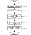
- an ultrasonic reception signal is acquired (step S10).
- This ultrasonic reception signal is output from the transmission / reception unit 22 as a parallel ultrasonic reception signal, and is converted into serial element data by the data format conversion unit 26.
- the serial element data is input to the element data memory 28 and temporarily stored together with the depth information of the transmission focus position of the ultrasonic beam (step S12).
- the primarily stored element data is transferred to the arithmetic processing unit 30 (B mode), and various processes such as image generation and display, sound speed determination, and the like are performed (step S14).
- the range of element data to be stored (at least one of the numerical aperture (number of channels) and the number of sample points) is determined by the arithmetic processing unit 30 based on the depth information of the received echo (step S16).
- the storage target determination process in step S16 will be described later.
- the element data determined to be stored is transferred to the storage memory 34 and stored (step S18).
- FIG. 3 is a flowchart showing a first embodiment of determination processing (step S16) of element data to be stored.
- the arithmetic processing unit 30 determines the numerical aperture and position of the element data to be stored based on the depth information (step S22).
- the element data to be stored includes, for example, information related to the subject OBJ (for example, identification information of the subject OBJ (patient), storage date and time of the element data, etc.), information related to ultrasonic transmission / reception conditions (for example, transmission / reception mode, frequency, The transmission / reception rate, transmission / reception address, transmission focus position coordinates corresponding to each element data, depth information, etc.) are stored in the storage memory 34.
- the intensity of the ultrasonic reception signal becomes stronger as the position of the transmission focus position in the depth direction is shallower (closer to the ultrasonic probe, -Z side) and deeper (farther from the ultrasonic probe, + Z It becomes weaker toward the side).
- the scattering angle ⁇ of the ultrasonic echo received by the element An located at the end of the ultrasonic probe 18 becomes large. For this reason, the noise contained in the ultrasonic wave reception signal increases. Therefore, in the determination of the numerical aperture of the element data to be stored, the determination is made such that the smaller the position of the received echo in the depth direction, the smaller the numerical aperture to be stored, and the larger the depth.
- the channel of the element data to be stored is, for example, evenly distributed in the ⁇ X direction with the element Ao at the position immediately below the transmission focus position Xo (the position where the X coordinate is the same) at the time of acquiring the element data as the center (The same number of channels are distributed in the ⁇ X directions around the element Ao).
- the element data channels to be stored may be limited to only those used for generating an image (B-mode image).
- B-mode image For example, when the element data corresponding to all channels temporarily stored in the element data memory 28 is stored in the storage memory 34, the element data outside the reception aperture determined based on the reception F value is excluded from the storage target. To do. Thereby, the data amount of the element data to be stored can be compressed. Further, by storing the reception F value or the reception numerical aperture at each depth in the auxiliary information of the element data to be stored (for example, information in the header portion of the element data), it is possible to create a B-mode image or the like. Necessary element data can be reconstructed.
- FIG. 5 is a diagram schematically showing the relationship between the numerical aperture (number of channels) of the element data to be stored and the depth of the region of interest.
- the X-axis indicates the channel position (scan direction) of the element data
- the Z-axis indicates the ultrasonic wave reception time corresponding to the depth direction or depth of the subject OBJ.
- the numerical aperture (number of channels) of the element data to be stored is the maximum value Nmax in the deepest region (maximum depth Lmax) of the region scanned by the ultrasonic beam.
- element data for all channels is represented by a rectangular area Va.
- the data amount of element data for all channels is represented by the area (Lmax ⁇ Nmax) of the rectangular region Va.
- the element data to be stored is a substantially triangular or trapezoidal area whose width in the X direction narrows toward the element Ao immediately below the position Xo of the reflection source of the ultrasonic echo (received echo) at the time of acquiring the element data. It is represented by Vs.
- the data amount of the element data to be stored is represented by the area of the region Vs.
- the data amount of the element data to be stored is the data amount of the element data for all channels (Lmax ⁇ Nmax).
- FIG. 6 shows an example in which the position of the reflection source of the ultrasonic echo (received echo) is from the end of the ultrasonic probe 18.
- the element data to be stored is a part of an isosceles triangle whose apex is the vicinity of the element A1 immediately below the position Xo of the reflection source of the ultrasonic echo (received echo) and whose base length is Nmax. And is represented by a region V S ′ included in the rectangular region Va corresponding to the scan range.
- the range of element data to be stored is limited based on the depth of received echoes and the numerical aperture (number of channels).
- element data before beam forming can be stored with a low capacity, so that a desired image such as a B-mode image can be created and analyzed, and an arbitrary transmission focus in the subject OBJ Saved for determination of the sound speed value at the position (local sound speed value) and the optimum sound speed value (for example, the sound speed value at which at least one of the contrast and sharpness of the image at the transmission focus position is highest in the B-mode image)
- the element data can be reprocessed.
- the range of element data to be stored is limited based on the number of sample points in the depth direction.
- FIG. 7 is a flowchart showing a second embodiment of determination processing of element data to be stored.
- the arithmetic processing unit 30 reads the depth information of the transmission focus position when acquiring the element data temporarily stored in step S12 (step S30).
- the arithmetic processing unit 30 determines the range (number of samples) in the depth direction of the element data to be stored based on the depth information (step S32).
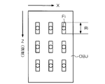
- FIG. 8 is a diagram schematically showing the relationship between the number of element data samples to be stored and the depth of the region of interest.
- the X axis indicates the channel position (scan direction) of the element data
- the Z axis indicates the ultrasonic wave reception time corresponding to the depth direction or depth of the subject OBJ.
- the range in the depth direction (Z direction) of what is to be saved from the element data acquired when obtaining the optimum sound velocity value is limited.
- the depth of the transmission focus position (or reception echo position) Fi is shallower (as the ⁇ Z side)
- the number of sample points of the element data is increased (the range Ri in the depth direction in which the element data is acquired is increased).
- the deeper the transmission focus position Fi is (the more the + Z side)
- the smaller the number of sample points of the element data the range Ri in the depth direction in which the element data is acquired is narrowed.
- the range of element data to be stored may be limited to the vicinity of the transmission focus position Fi.
- the memory capacity necessary for storing the element data before beam forming can be reduced.
- the element data to be stored may be associated with the B-mode image data generated in step S14 of FIG. 2 or the element data thinned out for creating the B-mode image and stored in the storage memory 34. Is possible. As a result, it is possible to perform processing such as superimposing and displaying an image indicating the sound speed to be stored in the present embodiment on the B-mode image data.
- the quality of element data is determined for each transmission focus position, and the element data to be stored is determined based on the quality determination result.
- FIG. 9 is a flowchart showing a third embodiment of determination processing of element data to be stored.
- the quality of element data is determined (step S40).
- the quality of the element data is determined based on, for example, the collapse of the waveform of the ultrasonic reception signal.
- the arithmetic processing unit 30 calculates a parameter representing the quality of element data.
- the parameter indicating the quality of the element data is, for example, the difference between the waveform of the ultrasonic beam transmitted when acquiring the element data and the waveform of the ultrasonic reception signal after the phase matching addition of the reception focus or element data, The absolute value of the difference, the integrated value of the difference or the absolute value of the difference within a predetermined time, or a value obtained by normalizing them.
- the arithmetic processing unit 30 determines that the quality of the element data is low when the quality parameter is equal to or higher than the threshold, and determines that the quality of the element data is high when the quality parameter is less than the threshold. To do.
- the arithmetic processing unit 30 reads the depth information of the transmission focus position when acquiring the element data temporarily stored in step S12 (step S42).
- the arithmetic processing unit 30 excludes element data determined to be low in quality from the storage target based on the information on the quality of the element data.
- the arithmetic processing unit 30 selects the element data to be stored based on the depth information acquired in step S42 from the element data determined to have high quality in the same manner as in the second embodiment.
- the range (number of samples) in the depth direction is determined (step S44).
- a correlation value obtained by calculating the correlation between the element data and the parabola may be used as the parameter indicating the quality of the element data in step S40.
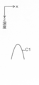
- FIG. 10A to FIG. 10C are diagrams for explaining a method for calculating the quality of element data by correlation calculation with a parabola.
- the X axis indicates the channel position (scan direction) of the element data
- the Z axis indicates the ultrasonic wave reception time corresponding to the depth direction or depth of the subject OBJ.
- the element data is expected to be ideally a parabolic shape centered on the transmission aperture channel. Therefore, the correlation between the parabola C1 as shown in FIG. 10A and the element data received by the ultrasound probe 18 is calculated to obtain a correlation value, and this correlation value is used as a parameter representing the quality of the element data. be able to.
- step S40 Since the element data D1 shown in FIG. 10B has a high correlation value with the parabola C1, if the correlation value is equal to or greater than the threshold value, it is determined that the quality is high in step S40. Since the element data D2 shown in FIG. 10C has a low correlation value with the parabola C1, if the correlation value is less than the threshold value, it is determined that the quality is low in step S40.
- element data for example, an image generated based on the element data, a sound speed determination result based on the element data, the waveform of the ultrasonic reception signal is greatly collapsed and considered to be low quality
- element data are excluded from the scope of storage. This makes it possible to more effectively reduce the memory capacity required to store the element data before beam forming.
- the limitation on the numerical aperture of element data according to the first embodiment and the limitation on the number of sample points of element data in the depth direction of the subject in the second and third embodiments can be performed together. Thereby, the data amount of the element data to be stored can be further reduced.
- the ultrasonic transducer (element 20) is arranged one-dimensionally has been described.
- the present invention is not limited to this.
- the ultrasonic transducer is arranged in a two-dimensional manner, or the ultrasonic transducer is not a flat surface but an arbitrary curved surface (for example, a convex surface that is convex with respect to the object OBJ). ) Can also be applied.
- SYMBOLS 10 ... Ultrasonic signal processing apparatus, 12 ... Control part (control processor), 14 ... Operation part, 16 ... Display part, 18 ... Ultrasonic probe (probe), 20 ... Ultrasonic transducer (element), 22 ... Transmission / reception unit, 24 ... Transmission / reception control unit, 26 ... Data format conversion unit, 28 ... Element data memory, 30 ... Operation processing unit (processor for calculation), 32 ... Primary storage memory, 34 ... Storage memory
Landscapes
- Health & Medical Sciences (AREA)
- Life Sciences & Earth Sciences (AREA)
- Engineering & Computer Science (AREA)
- Physics & Mathematics (AREA)
- Molecular Biology (AREA)
- Surgery (AREA)
- Pathology (AREA)
- Radiology & Medical Imaging (AREA)
- Biophysics (AREA)
- Biomedical Technology (AREA)
- Heart & Thoracic Surgery (AREA)
- Medical Informatics (AREA)
- Veterinary Medicine (AREA)
- Nuclear Medicine, Radiotherapy & Molecular Imaging (AREA)
- Animal Behavior & Ethology (AREA)
- General Health & Medical Sciences (AREA)
- Public Health (AREA)
- Gynecology & Obstetrics (AREA)
- Computer Vision & Pattern Recognition (AREA)
- Computer Networks & Wireless Communication (AREA)
- General Physics & Mathematics (AREA)
- Radar, Positioning & Navigation (AREA)
- Remote Sensing (AREA)
- Ultra Sonic Daignosis Equipment (AREA)
Priority Applications (1)
| Application Number | Priority Date | Filing Date | Title |
|---|---|---|---|
| US14/537,613 US10143444B2 (en) | 2012-05-25 | 2014-11-10 | Ultrasonic signal processing device and ultrasonic signal processing method |
Applications Claiming Priority (2)
| Application Number | Priority Date | Filing Date | Title |
|---|---|---|---|
| JP2012-119913 | 2012-05-25 | ||
| JP2012119913A JP5869958B2 (ja) | 2012-05-25 | 2012-05-25 | 超音波信号処理装置および超音波信号処理方法 |
Related Child Applications (1)
| Application Number | Title | Priority Date | Filing Date |
|---|---|---|---|
| US14/537,613 Continuation US10143444B2 (en) | 2012-05-25 | 2014-11-10 | Ultrasonic signal processing device and ultrasonic signal processing method |
Publications (1)
| Publication Number | Publication Date |
|---|---|
| WO2013176046A1 true WO2013176046A1 (fr) | 2013-11-28 |
Family
ID=49623740
Family Applications (1)
| Application Number | Title | Priority Date | Filing Date |
|---|---|---|---|
| PCT/JP2013/063761 Ceased WO2013176046A1 (fr) | 2012-05-25 | 2013-05-17 | Dispositif de traitement de signaux ultrasonores et procédé de traitement de signaux ultrasonores |
Country Status (3)
| Country | Link |
|---|---|
| US (1) | US10143444B2 (fr) |
| JP (1) | JP5869958B2 (fr) |
| WO (1) | WO2013176046A1 (fr) |
Families Citing this family (4)
| Publication number | Priority date | Publication date | Assignee | Title |
|---|---|---|---|---|
| WO2013176045A1 (fr) * | 2012-05-25 | 2013-11-28 | 富士フイルム株式会社 | Dispositif de traitement de signal ultrasonore et procédé de traitement de signal ultrasonore |
| JP2015000288A (ja) * | 2013-06-18 | 2015-01-05 | キヤノン株式会社 | 被検体情報取得装置およびその制御方法ならびに音響信号取得装置およびその制御方法 |
| WO2017056566A1 (fr) * | 2015-09-29 | 2017-04-06 | 富士フイルム株式会社 | Système de calcul de vitesse sonique et procédé de calcul de vitesse sonique |
| CN115944318B (zh) * | 2022-12-29 | 2024-10-01 | 深圳市捷美瑞科技有限公司 | 一种自动调节最佳测量深度的方法及系统 |
Citations (3)
| Publication number | Priority date | Publication date | Assignee | Title |
|---|---|---|---|---|
| JPH0364607U (fr) * | 1989-10-30 | 1991-06-24 | ||
| JPH0444906U (fr) * | 1990-08-14 | 1992-04-16 | ||
| JPH07303640A (ja) * | 1994-03-16 | 1995-11-21 | Fujitsu Ltd | 超音波診断装置 |
Family Cites Families (7)
| Publication number | Priority date | Publication date | Assignee | Title |
|---|---|---|---|---|
| JPH11164831A (ja) | 1997-12-03 | 1999-06-22 | Aloka Co Ltd | 超音波診断装置 |
| EP1330815A2 (fr) * | 2000-03-15 | 2003-07-30 | The Regents Of The University Of California | Procede et dispositif de concentration dynamique d'energie ultrasonore |
| JP2003102730A (ja) | 2001-09-28 | 2003-04-08 | Toshiba Medical System Co Ltd | 超音波診断装置 |
| JP2005279287A (ja) | 2005-05-17 | 2005-10-13 | Aloka Co Ltd | 超音波診断装置 |
| US20100138191A1 (en) * | 2006-07-20 | 2010-06-03 | James Hamilton | Method and system for acquiring and transforming ultrasound data |
| JP4717109B2 (ja) * | 2008-12-04 | 2011-07-06 | 日立アロカメディカル株式会社 | 超音波診断装置 |
| US9775585B2 (en) * | 2011-06-15 | 2017-10-03 | Toshiba Medical Systems Corporation | Variable power saving processing scheme for ultrasound beamformer functionality |
-
2012
- 2012-05-25 JP JP2012119913A patent/JP5869958B2/ja not_active Expired - Fee Related
-
2013
- 2013-05-17 WO PCT/JP2013/063761 patent/WO2013176046A1/fr not_active Ceased
-
2014
- 2014-11-10 US US14/537,613 patent/US10143444B2/en not_active Expired - Fee Related
Patent Citations (3)
| Publication number | Priority date | Publication date | Assignee | Title |
|---|---|---|---|---|
| JPH0364607U (fr) * | 1989-10-30 | 1991-06-24 | ||
| JPH0444906U (fr) * | 1990-08-14 | 1992-04-16 | ||
| JPH07303640A (ja) * | 1994-03-16 | 1995-11-21 | Fujitsu Ltd | 超音波診断装置 |
Also Published As
| Publication number | Publication date |
|---|---|
| JP2013244194A (ja) | 2013-12-09 |
| US20150065885A1 (en) | 2015-03-05 |
| JP5869958B2 (ja) | 2016-02-24 |
| US10143444B2 (en) | 2018-12-04 |
Similar Documents
| Publication | Publication Date | Title |
|---|---|---|
| JP5389722B2 (ja) | 超音波診断装置及びその作動方法 | |
| JP5946427B2 (ja) | 超音波検査装置、超音波検査方法、プログラム及び記録媒体 | |
| EP2623034A1 (fr) | Dispositif de génération d'image échographique, procédé de génération d'image échographique, et programme | |
| WO2012002421A1 (fr) | Dispositif de diagnostic par ultrasons et procédé de diagnostic par ultrasons | |
| JP5800324B2 (ja) | 超音波診断装置、超音波画像生成方法およびプログラム | |
| JP5948411B2 (ja) | 超音波信号処理装置および超音波信号処理方法 | |
| JP5623160B2 (ja) | 超音波診断装置及びその作動方法 | |
| JP2009061086A (ja) | 超音波診断装置、並びに、画像処理方法及びプログラム | |
| JP5869958B2 (ja) | 超音波信号処理装置および超音波信号処理方法 | |
| JP2010234013A (ja) | 超音波診断装置及び超音波診断方法 | |
| US8398548B2 (en) | Ultrasound diagnostic apparatus and ultrasound diagnostic method | |
| JP5623157B2 (ja) | 超音波診断装置及びその作動方法 | |
| US10788459B2 (en) | Ultrasound diagnostic apparatus, ultrasound image generation method, and recording medium | |
| WO2014050889A1 (fr) | Dispositif d'inspection par ultrasons, procédé de traitement de signal pour dispositif d'inspection par ultrasons, et programme | |
| JP5836241B2 (ja) | 超音波検査装置、超音波検査装置の信号処理方法およびプログラム | |
| JP5829198B2 (ja) | 超音波検査装置、超音波検査装置の信号処理方法およびプログラム | |
| US11051789B2 (en) | Ultrasound image diagnostic apparatus | |
| JP2013102959A (ja) | 超音波診断装置及び方法 | |
| WO2013073514A1 (fr) | Dispositif et procédé de diagnostic échographique | |
| WO2013176255A1 (fr) | Dispositif de diagnostic par ultrasons et procédé de traitement de données | |
| JP2013244195A (ja) | 超音波信号処理装置および超音波信号処理方法 | |
| JP5681755B2 (ja) | 超音波診断装置及びその作動方法 |
Legal Events
| Date | Code | Title | Description |
|---|---|---|---|
| 121 | Ep: the epo has been informed by wipo that ep was designated in this application |
Ref document number: 13794016 Country of ref document: EP Kind code of ref document: A1 |
|
| NENP | Non-entry into the national phase |
Ref country code: DE |
|
| 122 | Ep: pct application non-entry in european phase |
Ref document number: 13794016 Country of ref document: EP Kind code of ref document: A1 |