WO2013176098A1 - Dispositif de ponction - Google Patents
Dispositif de ponction Download PDFInfo
- Publication number
- WO2013176098A1 WO2013176098A1 PCT/JP2013/063998 JP2013063998W WO2013176098A1 WO 2013176098 A1 WO2013176098 A1 WO 2013176098A1 JP 2013063998 W JP2013063998 W JP 2013063998W WO 2013176098 A1 WO2013176098 A1 WO 2013176098A1
- Authority
- WO
- WIPO (PCT)
- Prior art keywords
- puncture
- puncture needle
- insertion portion
- separation distance
- needle assembly
- Prior art date
- Legal status (The legal status is an assumption and is not a legal conclusion. Google has not performed a legal analysis and makes no representation as to the accuracy of the status listed.)
- Ceased
Links
Images


Classifications
-
- A—HUMAN NECESSITIES
- A61—MEDICAL OR VETERINARY SCIENCE; HYGIENE
- A61B—DIAGNOSIS; SURGERY; IDENTIFICATION
- A61B17/00—Surgical instruments, devices or methods
- A61B17/04—Surgical instruments, devices or methods for suturing wounds; Holders or packages for needles or suture materials
- A61B17/06—Needles ; Sutures; Needle-suture combinations; Holders or packages for needles or suture materials
- A61B17/06066—Needles, e.g. needle tip configurations
- A61B17/06109—Big needles, either gripped by hand or connectable to a handle
-
- A—HUMAN NECESSITIES
- A61—MEDICAL OR VETERINARY SCIENCE; HYGIENE
- A61B—DIAGNOSIS; SURGERY; IDENTIFICATION
- A61B17/00—Surgical instruments, devices or methods
- A61B17/34—Trocars; Puncturing needles
- A61B17/3468—Trocars; Puncturing needles for implanting or removing devices, e.g. prostheses, implants, seeds, wires
-
- A—HUMAN NECESSITIES
- A61—MEDICAL OR VETERINARY SCIENCE; HYGIENE
- A61B—DIAGNOSIS; SURGERY; IDENTIFICATION
- A61B17/00—Surgical instruments, devices or methods
- A61B17/34—Trocars; Puncturing needles
- A61B17/3403—Needle locating or guiding means
-
- A—HUMAN NECESSITIES
- A61—MEDICAL OR VETERINARY SCIENCE; HYGIENE
- A61B—DIAGNOSIS; SURGERY; IDENTIFICATION
- A61B17/00—Surgical instruments, devices or methods
- A61B17/34—Trocars; Puncturing needles
- A61B17/3494—Trocars; Puncturing needles with safety means for protection against accidental cutting or pricking, e.g. limiting insertion depth, pressure sensors
-
- A—HUMAN NECESSITIES
- A61—MEDICAL OR VETERINARY SCIENCE; HYGIENE
- A61B—DIAGNOSIS; SURGERY; IDENTIFICATION
- A61B5/00—Measuring for diagnostic purposes; Identification of persons
- A61B5/06—Devices, other than using radiation, for detecting or locating foreign bodies ; Determining position of diagnostic devices within or on the body of the patient
- A61B5/065—Determining position of the probe employing exclusively positioning means located on or in the probe, e.g. using position sensors arranged on the probe
-
- A—HUMAN NECESSITIES
- A61—MEDICAL OR VETERINARY SCIENCE; HYGIENE
- A61B—DIAGNOSIS; SURGERY; IDENTIFICATION
- A61B5/00—Measuring for diagnostic purposes; Identification of persons
- A61B5/68—Arrangements of detecting, measuring or recording means, e.g. sensors, in relation to patient
- A61B5/6846—Arrangements of detecting, measuring or recording means, e.g. sensors, in relation to patient specially adapted to be brought in contact with an internal body part, i.e. invasive
- A61B5/6847—Arrangements of detecting, measuring or recording means, e.g. sensors, in relation to patient specially adapted to be brought in contact with an internal body part, i.e. invasive mounted on an invasive device
- A61B5/6848—Needles
-
- A—HUMAN NECESSITIES
- A61—MEDICAL OR VETERINARY SCIENCE; HYGIENE
- A61B—DIAGNOSIS; SURGERY; IDENTIFICATION
- A61B5/00—Measuring for diagnostic purposes; Identification of persons
- A61B5/68—Arrangements of detecting, measuring or recording means, e.g. sensors, in relation to patient
- A61B5/6846—Arrangements of detecting, measuring or recording means, e.g. sensors, in relation to patient specially adapted to be brought in contact with an internal body part, i.e. invasive
- A61B5/6847—Arrangements of detecting, measuring or recording means, e.g. sensors, in relation to patient specially adapted to be brought in contact with an internal body part, i.e. invasive mounted on an invasive device
- A61B5/6852—Catheters
-
- A—HUMAN NECESSITIES
- A61—MEDICAL OR VETERINARY SCIENCE; HYGIENE
- A61B—DIAGNOSIS; SURGERY; IDENTIFICATION
- A61B5/00—Measuring for diagnostic purposes; Identification of persons
- A61B5/68—Arrangements of detecting, measuring or recording means, e.g. sensors, in relation to patient
- A61B5/6846—Arrangements of detecting, measuring or recording means, e.g. sensors, in relation to patient specially adapted to be brought in contact with an internal body part, i.e. invasive
- A61B5/6867—Arrangements of detecting, measuring or recording means, e.g. sensors, in relation to patient specially adapted to be brought in contact with an internal body part, i.e. invasive specially adapted to be attached or implanted in a specific body part
- A61B5/6874—Bladder
-
- A—HUMAN NECESSITIES
- A61—MEDICAL OR VETERINARY SCIENCE; HYGIENE
- A61B—DIAGNOSIS; SURGERY; IDENTIFICATION
- A61B5/00—Measuring for diagnostic purposes; Identification of persons
- A61B5/68—Arrangements of detecting, measuring or recording means, e.g. sensors, in relation to patient
- A61B5/6846—Arrangements of detecting, measuring or recording means, e.g. sensors, in relation to patient specially adapted to be brought in contact with an internal body part, i.e. invasive
- A61B5/6885—Monitoring or controlling sensor contact pressure
-
- A—HUMAN NECESSITIES
- A61—MEDICAL OR VETERINARY SCIENCE; HYGIENE
- A61B—DIAGNOSIS; SURGERY; IDENTIFICATION
- A61B17/00—Surgical instruments, devices or methods
- A61B2017/00017—Electrical control of surgical instruments
- A61B2017/00115—Electrical control of surgical instruments with audible or visual output
- A61B2017/00119—Electrical control of surgical instruments with audible or visual output alarm; indicating an abnormal situation
-
- A—HUMAN NECESSITIES
- A61—MEDICAL OR VETERINARY SCIENCE; HYGIENE
- A61B—DIAGNOSIS; SURGERY; IDENTIFICATION
- A61B17/00—Surgical instruments, devices or methods
- A61B2017/00743—Type of operation; Specification of treatment sites
- A61B2017/00805—Treatment of female stress urinary incontinence
-
- A—HUMAN NECESSITIES
- A61—MEDICAL OR VETERINARY SCIENCE; HYGIENE
- A61B—DIAGNOSIS; SURGERY; IDENTIFICATION
- A61B17/00—Surgical instruments, devices or methods
- A61B17/34—Trocars; Puncturing needles
- A61B17/3403—Needle locating or guiding means
- A61B2017/3413—Needle locating or guiding means guided by ultrasound
-
- A—HUMAN NECESSITIES
- A61—MEDICAL OR VETERINARY SCIENCE; HYGIENE
- A61B—DIAGNOSIS; SURGERY; IDENTIFICATION
- A61B17/00—Surgical instruments, devices or methods
- A61B17/34—Trocars; Puncturing needles
- A61B2017/348—Means for supporting the trocar against the body or retaining the trocar inside the body
- A61B2017/3492—Means for supporting the trocar against the body or retaining the trocar inside the body against the outside of the body
-
- A—HUMAN NECESSITIES
- A61—MEDICAL OR VETERINARY SCIENCE; HYGIENE
- A61B—DIAGNOSIS; SURGERY; IDENTIFICATION
- A61B34/00—Computer-aided surgery; Manipulators or robots specially adapted for use in surgery
- A61B34/20—Surgical navigation systems; Devices for tracking or guiding surgical instruments, e.g. for frameless stereotaxis
- A61B2034/2046—Tracking techniques
- A61B2034/2051—Electromagnetic tracking systems
-
- A—HUMAN NECESSITIES
- A61—MEDICAL OR VETERINARY SCIENCE; HYGIENE
- A61B—DIAGNOSIS; SURGERY; IDENTIFICATION
- A61B34/00—Computer-aided surgery; Manipulators or robots specially adapted for use in surgery
- A61B34/20—Surgical navigation systems; Devices for tracking or guiding surgical instruments, e.g. for frameless stereotaxis
- A61B2034/2046—Tracking techniques
- A61B2034/2055—Optical tracking systems
-
- A—HUMAN NECESSITIES
- A61—MEDICAL OR VETERINARY SCIENCE; HYGIENE
- A61B—DIAGNOSIS; SURGERY; IDENTIFICATION
- A61B5/00—Measuring for diagnostic purposes; Identification of persons
- A61B5/20—Measuring for diagnostic purposes; Identification of persons for measuring urological functions restricted to the evaluation of the urinary system
- A61B5/202—Assessing bladder functions, e.g. incontinence assessment
-
- A—HUMAN NECESSITIES
- A61—MEDICAL OR VETERINARY SCIENCE; HYGIENE
- A61B—DIAGNOSIS; SURGERY; IDENTIFICATION
- A61B8/00—Diagnosis using ultrasonic, sonic or infrasonic waves
- A61B8/42—Details of probe positioning or probe attachment to the patient
-
- A—HUMAN NECESSITIES
- A61—MEDICAL OR VETERINARY SCIENCE; HYGIENE
- A61F—FILTERS IMPLANTABLE INTO BLOOD VESSELS; PROSTHESES; DEVICES PROVIDING PATENCY TO, OR PREVENTING COLLAPSING OF, TUBULAR STRUCTURES OF THE BODY, e.g. STENTS; ORTHOPAEDIC, NURSING OR CONTRACEPTIVE DEVICES; FOMENTATION; TREATMENT OR PROTECTION OF EYES OR EARS; BANDAGES, DRESSINGS OR ABSORBENT PADS; FIRST-AID KITS
- A61F2/00—Filters implantable into blood vessels; Prostheses, i.e. artificial substitutes or replacements for parts of the body; Appliances for connecting them with the body; Devices providing patency to, or preventing collapsing of, tubular structures of the body, e.g. stents
- A61F2/0004—Closure means for urethra or rectum, i.e. anti-incontinence devices or support slings against pelvic prolapse
- A61F2/0031—Closure means for urethra or rectum, i.e. anti-incontinence devices or support slings against pelvic prolapse for constricting the lumen; Support slings for the urethra
- A61F2/0036—Closure means for urethra or rectum, i.e. anti-incontinence devices or support slings against pelvic prolapse for constricting the lumen; Support slings for the urethra implantable
Definitions
- the present invention relates to a puncture device.
- Urinary incontinence particularly stress urinary incontinence, urine leakage occurs due to abdominal pressure applied during normal exercise, laughing, coughing, sneezing, etc.
- the cause of this is, for example, that the pelvic floor muscle, which is a muscle that supports the urethra, is loosened due to childbirth and the like.
- Surgical therapy is effective for the treatment of urinary incontinence.
- a tape-like implant called “sling” is used, and the sling is placed in the body, and the urethra is supported by the sling (see, for example, Patent Document 1). ).
- the surgeon incises the vagina with a scalpel, peels off the space between the urethra and the vagina, and uses the puncture needle to connect the peeled site and the outside through the pelvic obturator. Forming a puncture hole.
- the formation of the puncture hole by the puncture needle is performed by a blind operation only with the touch of the finger. Then, the sling is placed in the body using such a puncture hole.
- the method of placing a sling using a conventional medical instrument such as the scalpel has the disadvantage that it is highly invasive and burdens the patient. Also, when incising the vagina with a scalpel and peeling between the urethra and vagina, there is a possibility that the peeling direction is wrong, the sling cannot be placed in an appropriate position, or the urethra etc. may be damaged, The surgeon himself may damage the fingertip. In addition, when the patient moves, the puncture path of the puncture needle may deviate from the target when the puncture hole is formed by the puncture needle, and may not be noticed.
- An object of the present invention is to prevent puncture of a portion that should not be punctured when puncturing a living tissue with a puncture needle, while reducing the burden on the patient, increasing patient safety, and An object of the present invention is to provide a puncture device that is highly safe for the surgeon.
- the present invention includes an insertion part that can be inserted into a living body, A puncture needle that punctures a living tissue in the vicinity of the insertion portion in a state where the insertion portion is inserted into the living body; A puncture apparatus comprising: a detection unit configured to detect information related to a positional relationship between a distal end portion of the puncture needle and the insertion portion.
- the insertion part is preferably a longitudinal urethral insertion part inserted into the urethra or a longitudinal vagina insertion part inserted into the vagina.
- the insertion portion is a longitudinal urethral insertion portion that is inserted into the urethra, It is preferable to have a restricting portion that is provided in the urethra insertion portion and restricts the longitudinal position of the urethral insertion portion in the urethra.
- the detection means has a function of detecting information related to the positional relationship between the distal end portion of the puncture needle and two different portions in the longitudinal direction of the insertion portion.
- one of the two insertion portions may be a longitudinal urethral insertion portion that is inserted into the urethra, and the other is a longitudinal vagina insertion portion that is inserted into the vagina. preferable.
- the detection means has a function of detecting information related to the positional relationship between the distal end portion of the puncture needle and two different portions in the longitudinal direction of the insertion portion.
- the detection means has a function of detecting information related to a positional relationship between one of the two insertion portions and the other.
- the puncture device has an informing means for informing information based on a detection result of the detecting means.
- the puncture device has a discriminating means for discriminating whether or not a separation distance between the one and the other is not less than a minimum value of an allowable range It is preferable that a warning is given by the notification means when the determination means determines that the separation distance between the one and the other is smaller than the minimum value of the allowable range.
- the determination means has a function of determining whether or not a separation distance between the one and the other is equal to or less than a maximum value of an allowable range, It is preferable that the notification means warns when the determination means determines that the separation distance between the one and the other is larger than the maximum value of the allowable range.
- the puncture device has an informing means for informing information based on a detection result of the detecting means.
- the puncture device of the present invention having a determination means for determining whether or not a separation distance between the distal end portion of the puncture needle and the insertion portion is equal to or greater than a minimum value of an allowable range, It is preferable that a warning is given by the notification means when the determination means determines that the separation distance between the distal end portion of the puncture needle and the insertion portion is smaller than the minimum value of the allowable range.
- the puncture device of the present invention has a discriminating means for discriminating whether or not the separation distance between the distal end portion of the puncture needle and the insertion portion is equal to or less than the maximum value of an allowable range, It is preferable that a warning is given by the notification means when the determination means determines that the separation distance between the distal end portion of the puncture needle and the insertion portion is larger than the maximum value of the allowable range.
- a notification means for notifying information based on a detection result of the detection means, Comparing means for comparing one and the other of the separation distance between the distal end portion of the puncture needle and the two different portions in the longitudinal direction of the insertion portion; It is preferable that the notification means notifies based on a comparison result of the comparison means.
- the puncture needle is curved in an arc shape, A support portion that supports the puncture needle so as to be rotatable about the central axis of the arc, and a direction in which the needle tip of the puncture needle is directed when the puncture needle is rotated, provided at a position different from the support portion. It is preferable that it has a guide part located in.
- the puncture needle is configured by a tubular body curved in an arc shape, and is detachably attached to the outer tube having one end opening with one end opened, and the one end opening.
- a needle body having a rounded non-sharp needle tip, and comprising a puncture needle assembly that can be assembled by attaching the needle body to the one end opening,
- a support portion that supports the puncture needle assembly in the assembled state so as to be rotatable about a central axis of the arc of the outer tube, and is provided at a position different from the support portion, and the puncture needle assembly is rotated. It is preferable to have a guide part positioned in the direction in which the needle tip is directed.
- the present invention when a living tissue is punctured with a puncture needle, it is possible to prevent puncturing a portion that should not be punctured, and the burden on the patient is low, and the safety of the patient is high. The safety of the surgeon is also high.
- the puncture device of the present invention when used for the treatment of female urinary incontinence, the insertion portion of the puncture device is inserted into the urethra, the puncture needle is rotated, and the living body is punctured by the puncture needle. At this time, since information regarding the positional relationship between the distal end portion of the puncture needle and the insertion portion can be detected, it is possible to prevent the puncture needle from puncturing the urethra.
- an implant for treating urinary incontinence when embedded, incision of the vaginal wall is unnecessary, and the implant can be embedded with a minimally invasive procedure. Further, the surgeon can also prevent the fingertip from being damaged.
- FIG. 1 is a partial cross-sectional view showing a first embodiment of the puncture device of the present invention.
- FIG. 2 is a diagram showing the puncture device shown in FIG.
- FIG. 3 is a block diagram showing a circuit configuration of the puncture apparatus shown in FIG.
- FIG. 4 is a flowchart showing a control operation of the control unit of the puncture apparatus shown in FIG.
- FIG. 5 is a diagram for explaining the procedure of the procedure when the puncture apparatus shown in FIG. 1 is used.
- FIG. 6 is a diagram for explaining the procedure of the procedure when the puncture apparatus shown in FIG. 1 is used.
- FIG. 7 is a view for explaining the procedure of the procedure when the puncture apparatus shown in FIG. 1 is used.
- FIG. 1 is a partial cross-sectional view showing a first embodiment of the puncture device of the present invention.
- FIG. 2 is a diagram showing the puncture device shown in FIG.
- FIG. 3 is a block diagram showing a circuit configuration of the puncture apparatus shown in
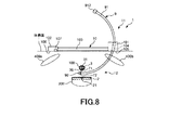
- FIG. 8 is a diagram for explaining the procedure of the procedure when the puncture apparatus shown in FIG. 1 is used.
- FIG. 9 is a diagram for explaining the procedure of the procedure when the puncture apparatus shown in FIG. 1 is used.
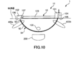
- FIG. 10 is a diagram for explaining the procedure of the procedure when the puncture apparatus shown in FIG. 1 is used.
- FIG. 11 is a diagram for explaining the procedure of the procedure when the puncture apparatus shown in FIG. 1 is used.
- FIG. 12 is a diagram for explaining the procedure of the procedure when the puncture apparatus shown in FIG. 1 is used.
- FIG. 13 is a partial cross-sectional view showing a second embodiment of the puncture device of the present invention.
- FIG. 14 shows the puncture device shown in FIG. FIG.
- FIG. 15 is a block diagram showing a circuit configuration of the puncture apparatus shown in FIG.
- FIG. 16 is a flowchart showing a control operation of the control unit of the puncture apparatus shown in FIG.
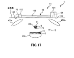
- FIG. 17 is a view for explaining the procedure of the procedure when the puncture apparatus shown in FIG. 13 is used.
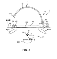
- FIG. 18 is a diagram for explaining the procedure of the procedure when the puncture apparatus shown in FIG. 13 is used.
- FIG. 19 is a diagram for explaining the procedure of the procedure when the puncture apparatus shown in FIG. 13 is used.
- FIG. 20 is a diagram for explaining the procedure of the procedure when the puncture apparatus shown in FIG. 13 is used.
- FIG. 21 is a diagram for explaining the procedure of the procedure when the puncture device shown in FIG. 13 is used.
- FIG. 21 is a diagram for explaining the procedure of the procedure when the puncture device shown in FIG. 13 is used.
- FIG. 22 is a diagram for explaining the procedure of the procedure when the puncture apparatus shown in FIG. 13 is used.
- FIG. 23 is a diagram for explaining the procedure of the procedure when the puncture apparatus shown in FIG. 13 is used.
- FIG. 24 is a diagram for explaining the procedure of the procedure when the puncture apparatus shown in FIG. 13 is used.
- FIG. 25 is a diagram showing a third embodiment of the puncture device of the present invention.
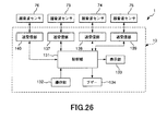
- FIG. 26 is a block diagram showing a circuit configuration of the puncture apparatus shown in FIG.
- FIG. 27 is a flowchart showing a control operation of the control unit of the puncture apparatus shown in FIG.
- FIG. 28 is a partial cross-sectional view showing a fourth embodiment of the puncture device of the present invention.
- FIG. 1 is a partial cross-sectional view showing a first embodiment of the puncture device of the present invention.
- 2 is a diagram showing the puncture device shown in FIG. 1.
- FIG. 2 (a) is a side view
- FIG. 2 (b) is a front view
- FIG. 2 (c) is a rear view
- FIG. ) Is a cross-sectional view taken along line AA in FIG.
- FIG. 3 is a block diagram showing a circuit configuration of the puncture apparatus shown in FIG.
- FIG. 4 is a flowchart showing a control operation of the control unit of the puncture apparatus shown in FIG. 5 to 12 are diagrams for explaining the procedure of the procedure when the puncture apparatus shown in FIG. 1 is used.
- the left side is the “tip” and the right side is the “base end”, and FIGS. 2 (a), 2 (b) and 2 (c). )
- the lower side is referred to as the “tip” and the upper side is referred to as the “base end”.
- each ultrasonic sensor and each reflection part are schematically shown in a large size for easy viewing, and the oblique lines in the living body are omitted.
- the puncture apparatus 1 shown in these drawings is an apparatus used when an urinary incontinence treatment for a woman, that is, an urinary incontinence treatment implant (in-vivo indwelling device) is embedded in a living body.
- the puncture device 1 includes a first device 11, a second device 12, and a device body 13.
- the first apparatus 11 includes a puncture needle assembly 9 and a support member 10 as puncture needles.
- the puncture needle assembly 9 is curved in an arc shape.
- the puncture needle assembly 9 includes an outer tube 91 configured by a tube curved in an arc shape, and an inner structure 94 configured by a needle body 92 and an implant 93.
- the puncture needle assembly 9 includes an assembled state (see FIGS. 1 and 6 to 9) in which the outer tube 91 and the inner structure 94 are assembled, and the outer tube 91 and the inner structure 94 from the assembled state. Can be separated (see FIGS. 10 to 12).
- the puncture needle assembly 9 is in an assembled state, and a urethral insertion portion 31 and a vaginal insertion portion 2 described later are inserted in the urethra and vagina, respectively, in the vicinity of the urethral insertion portion 31 and the vaginal insertion portion 2, that is, The living tissue between the urethral insertion part 31 and the vaginal insertion part 2 is punctured.
- the outer tube 91 has one end opening 911 having one end opened, and a grip 912 at the other end.
- the needle body 92 is detachably attached to the one end opening 911.
- the grip portion 912 is a portion that is gripped when the outer tube 91 is pulled out from the living tissue.
- center angle of the arcuate outer tube 91 is preferably 135 to 210 °, and more preferably 150 to 180 °.
- the needle body 92 has a mushroom shape, and the top portion thereof is a needle tip 921 that can puncture a living tissue.
- the needle tip 921 may be slightly rounded so that the operator does not accidentally puncture his / her finger or the like.
- a stepped portion 922 whose outer diameter changes sharply is formed at the proximal end portion of the needle body 92, that is, the portion opposite to the needle tip 921.
- the implant 93 is an implantable device for treating female urinary incontinence, and is a long member connected to the proximal end portion of the needle body 92.
- the implant 93 has a mesh shape and is flexible, and is placed in a living tissue together with the needle body 92 to support the urethra. For example, when the urethra is about to move toward the vagina wall, the implant 93 supports the urethra by pulling the urethra away from the vagina wall.
- the needle body 92 In the assembled state, the needle body 92 is attached to the one end opening 911 of the outer tube 91, and the implant 93 is inserted into the outer tube 91. In the disassembled state, the needle body 92 is detached from the one end opening 911 of the outer tube 91, and the implant 93 is removed from the outer tube 91.
- the constituent material of the outer tube 91 is not particularly limited, and examples thereof include a metal material such as stainless steel, aluminum, an aluminum alloy, titanium, or a titanium alloy. Moreover, it does not specifically limit as a constituent material of the needle body 92 and the implant 93, For example, various resin materials, fibers, etc. which have biocompatibility like a polypropylene etc. can be used.
- Two ultrasonic sensors (ultrasonic transducers) 71 and 72 for transmitting and receiving ultrasonic waves are installed at the distal end portion of the puncture needle assembly 9, that is, the outer peripheral surface of the distal end portion of the outer tube 91. ing.
- the ultrasonic sensor 71 transmits / receives ultrasonic waves to / from a reflection unit 36 of the urethral insertion unit 31 described later, that is, transmits ultrasonic waves to the reflection unit 36 and receives ultrasonic waves reflected by the reflection unit 36. Is.
- the ultrasonic sensor 72 transmits / receives ultrasonic waves to / from a reflection unit 21 of the vaginal insertion unit 2 described later, that is, transmits ultrasonic waves to the reflection unit 21 and reflects ultrasonic waves reflected by the reflection unit 21. To receive.
- Each of the ultrasonic sensors 71 and 72 has an ultrasonic transducer in which electrodes are formed on both surfaces of a piezoelectric body made of, for example, PZT (lead zirconate titanate).
- the ultrasonic sensor 71 is disposed on the inner peripheral side of an arc that is a curved shape of the puncture needle assembly 9 so as to be positioned on the urethra insertion portion 31 side when puncturing a living tissue with the puncture needle assembly 9. .
- an angle ⁇ 1 formed by the center line of the ultrasonic wave transmitted from the ultrasonic sensor 71 and the tangent line at the site where the ultrasonic sensor 71 of the outer tube 91 is installed is 15 to 75. It is preferably installed so as to be at 60 °, more preferably set at 30 to 60 °. In the illustrated configuration, ⁇ 1 is set to 45 °.
- the ultrasonic sensor 72 is disposed on the outer peripheral side of an arc that is a curved shape of the puncture needle assembly 9 so as to be positioned on the vaginal insertion portion 2 side when puncturing a living tissue with the puncture needle assembly 9. Yes.
- the ultrasonic sensor 72 has an angle ⁇ 2 formed by the center line of the ultrasonic wave transmitted from the ultrasonic sensor 72 and the tangent line at the site where the ultrasonic sensor 72 of the outer tube 91 is installed at 15 to 75. It is preferably installed so as to be at 60 °, more preferably set at 30 to 60 °. In the illustrated configuration, ⁇ 2 is set to 45 °.
- ultrasonic sensors is not limited to two, and may be one or three or more.
- the support member 10 is disposed at a position different from the support unit 101, that is, at a position different from the support unit 101, that is, at a distance from the support unit 101, and a connection that connects the support unit 101 and the guide unit 102. Part 103.
- the support portion 101 is a member formed of a rectangular parallelepiped or a cubic block body, and a through hole 104 penetrating the block body is formed.
- the puncture needle assembly 9 (outer tube 91) in an assembled state can be inserted through the through hole 104, and is curved with a curvature equal to that of the outer tube 91 (puncture needle assembly 9).
- the puncture needle assembly 9 in the assembled state is supported by the through hole 104 so as to be rotatable about an axis having the center O of the arc of the outer tube 91 as a central axis (see FIGS. 6 to 9).
- the lower surface 105 in FIG. 1 of the support portion 101 functions as a destination portion addressed to the body surface.
- the support part 101 is not limited to a block body, For example, the shape containing a curved surface may be sufficient.
- the guide portion 102 is a member that is formed of a rectangular parallelepiped or a cubic block body and is positioned in a direction in which the needle tip 921 of the needle body 92 faces when the assembled puncture needle assembly 9 rotates.
- the needle tip 921 of the needle body 92 is directed toward the center of the guide portion 102.
- the lower surface 106 of FIG. 1 of the guide portion 102 that is, the surface facing the needle tip 921 functions as a destination portion addressed to the body surface.
- the guide part 102 is not limited to a block body, For example, the shape containing a curved surface may be sufficient.
- the surface 106 of the guide unit 102 is provided with a reflection unit 107 that reflects ultrasonic waves.
- the position of the reflecting portion 107 is not particularly limited, in the present embodiment, the reflecting portion 107 punctures a living tissue with the puncture needle assembly 9, and the needle tip 921 of the puncture needle assembly 9 is attached to the reflecting portion 107.
- the ultrasonic sensor 71 is disposed at a position where the central axis of the ultrasonic wave penetrates, that is, at the end of the guide portion 102 on the connecting portion side.
- the reflecting portion 107 is not particularly limited as long as it can reflect ultrasonic waves.
- a metal material such as stainless steel, aluminum or aluminum alloy, titanium or titanium alloy, and the like. And having a plurality of minute irregularities formed on the surface.
- a plurality of minute irregularities may be formed on the surface of the guide part 102 as the reflection part 107.
- the connecting portion 103 is formed of a long body, and supports the support portion 101 and the guide portion 102 at both ends thereof. Thereby, the support part 101 and the guide part 102 are connected via the connection part 103.
- the puncture needle assembly 9 can be operated with the surface 106 of the guide portion 102 directed to the body surface (hereinafter this state is referred to as “use state”) (see FIGS. 5 to 12).
- the puncture hole for embedding the implant 93 with respect to a biological tissue can be formed by rotating the puncture needle assembly 9 about the center O of the arc of the outer tube 91 as a rotation center.
- the second device 12 includes a longitudinal vaginal insertion portion (insertion portion) 2 inserted into the vagina and a longitudinal urethral insertion portion (insertion portion) 31 inserted into the urethra. And a connecting portion 4 which is a connecting means for connecting the vaginal insertion portion 2 and the urethral insertion member 3 to each other.
- the shape of the vaginal insertion portion 2 is not particularly limited as long as it is a longitudinal shape, but in the present embodiment, it has a plate shape. And the width
- the vaginal insertion part 2 is curved. Thereby, when the vagina insertion part 2 is inserted into the vagina, the operative field can be directed to the front of the operator, and the operative field can be widened.
- the urethral insertion member 3 includes a urethral insertion portion 31 and a protrusion 32 that is formed at the proximal end portion of the urethral insertion portion 31 and protrudes from the urethral insertion portion toward the left side in FIG. .
- the shape of the urethral insertion portion 31 is not particularly limited as long as it is a longitudinal shape, but in the present embodiment, it has a rod shape. Further, the distal end portion of the urethral insertion portion 31 is rounded. Thereby, patient safety can be improved.
- the urethral insertion part 31 is curved in the same direction as the vaginal insertion part 2.
- the curvature of the urethral insertion portion 31 is set equal to that of the vaginal insertion portion 2.
- the posture of the urethral insertion portion 31 is set such that the separation distance between the urethral insertion portion 31 and the vaginal insertion portion 2 is constant along the longitudinal direction of the urethral insertion portion 31.
- the connecting portion 4 is fixed to the right side in FIG. 2A of the base end portion of the vaginal insertion portion 2.
- a bottomed hole 41 is formed in the connecting portion 4 along the left-right direction in FIGS. 2 (a) and 2 (d). The right side of the hole 41 in FIGS. 2A and 2D is open.
- the protrusion 32 of the urethral insertion member 3 is inserted into the hole 41 so as to be movable in the longitudinal direction.
- the adjustment means for adjusting the separation distance between the vaginal insertion portion 2 and the urethral insertion portion 31 is configured by the hole 41 of the connecting portion 4 and the protruding portion 32 of the urethral insertion member 3.
- the second device 12 has a male screw 51, and a female screw part 42 having a female screw screwed with the male screw 51 is formed in the connecting part 4.
- the tip of the male screw 51 comes into pressure contact with the protruding portion 32 of the urethra insertion member 3, and the movement of the urethra insertion member 3 with respect to the connecting portion 4 is prevented. Further, when the male screw 51 is rotated in the opposite direction, the tip of the male screw 51 is separated from the protruding portion 32, and the urethral insertion member 3 can be moved with respect to the connecting portion 4.
- the male screw 51 and the female screw portion 42 constitute a lock portion that switches between a state where the urethral insertion member 3 can move relative to the connecting portion 4 and a state where the movement of the urethral insertion member 3 is blocked.
- a balloon 61 that can be expanded and contracted is provided at the distal end of the urethra insertion part 31 as a restriction part that restricts the longitudinal position of the urethra insertion part 31 in the urethra.
- the balloon 61 is inserted into the patient's bladder when the second device 12 is used, and the balloon 61 is expanded and hooked onto the bladder neck, thereby fixing the position of the urethra insertion portion 31 relative to the bladder and urethra.
- a lumen 33 is formed in the urethral insertion portion 31.
- the distal end of the lumen 33 is opened in the balloon 61, and the proximal end is opened on the side surface of the proximal end portion of the urethral insertion portion 31.
- a port 34 communicating with the proximal end of the lumen 33 is formed at the proximal end of the urethral insertion portion 31.
- a balloon expansion device such as a syringe (not shown) is connected to the port 34, and the working fluid supplied from the balloon expansion device is sent into the balloon 61 through the lumen 33, or the working fluid is extracted and the balloon 61 is extracted.
- a liquid such as physiological saline, a gas, or the like can be used.
- the restricting part that restricts the position of the urethral insertion part 31 in the urethra is not limited to the balloon 61.
- a part of the urethral insertion portion 31 that is curved or a part of the urinary tract tissue surface that is grasped may be used.
- a reflection part 36 that reflects the ultrasonic wave transmitted from the ultrasonic sensor 71 is provided on the surface of the vagina insertion part 2 in the middle of the urethra insertion part 31.
- the reflecting portion 36 is not particularly limited as long as it can reflect ultrasonic waves.
- a metal material such as stainless steel, aluminum or aluminum alloy, titanium or titanium alloy, and the like. And having a plurality of minute irregularities formed on the surface.
- a plurality of minute irregularities may be formed on the surface of the urethral insertion portion 31 as the reflection portion 36.
- a reflecting portion 21 that reflects ultrasonic waves transmitted from the ultrasonic sensor 72 is provided on the surface of the urethral insertion portion 31 in the middle of the vaginal insertion portion 2.
- the reflecting portion 21 is not particularly limited as long as it can reflect ultrasonic waves.
- a metal material such as stainless steel, aluminum or aluminum alloy, titanium or titanium alloy, and the like. And having a plurality of minute irregularities formed on the surface.
- a plurality of minute irregularities may be formed on the surface of the vaginal insertion part 2 as the reflection part 21.
- the reflection part 36 is provided in a part of surface of the urethra insertion part 31, it is not restricted to this, For example, you may be provided in the whole surface of the urethra insertion part 31.
- the ultrasonic sensor 71 detects the shortest distance between the urethral insertion portion 31 and the portion of the puncture needle assembly 9 where the ultrasonic sensor 71 is installed.
- the reflection part 21 is provided in a part of surface of the vagina insertion part 2 in this embodiment, it is not restricted to this, For example, you may be provided in the whole surface of the vagina insertion part 2.
- FIG. the shortest distance between the vaginal insertion part 2 and the part where the ultrasonic sensor 72 of the puncture needle assembly 9 is installed is detected by the ultrasonic sensor 72 described later.
- the apparatus main body 13 includes a control unit 131, an operation unit 132 that performs each operation, a display unit 133 that is a notification unit, a buzzer 134 that is a notification unit, and ultrasonic sensors 71 and 72. It has transmission / reception sections 135 and 136 for transmitting and receiving signals.
- the transmission / reception units 135 and 136 of the apparatus main body 13 are electrically connected to the ultrasonic sensors 71 and 72 via cables (not shown), respectively.
- the control unit 131 is constituted by, for example, a microcomputer, receives an input signal from the operation unit 132, and controls the entire puncture apparatus 1 such as the display unit 133, the buzzer 134, the transmission / reception units 135 and 136, and the like.
- the positional relationship between the distal end portion of the puncture needle assembly 9, the urethral insertion portion 31, the vaginal insertion portion 2, and the guide portion 102 is determined by the control unit 131, the transmission / reception units 135 and 136, and the ultrasonic sensors 71 and 72.
- a detecting means for detecting information on is configured.
- the control unit 131 constitutes a determination unit and a comparison unit.
- the display unit 133 is not particularly limited, and examples thereof include a liquid crystal display device and a CRT.
- the transmission / reception units 135 and 136 transmit electrical signals for transmitting ultrasonic waves from the ultrasonic sensors 71 and 72 to the ultrasonic sensors 71 and 72, respectively, and the ultrasonic sensors 71 and 72 receive the ultrasonic waves. When electrical signals are transmitted from the ultrasonic sensors 71 and 72, the signals are received.
- the biological tissue is punctured by the puncture needle assembly 9 of the puncture device 1, and the puncture hole formed in the biological tissue penetrates the body surface on the support member 10 side of the first device 11, and the guide portion 102 side This is a non-through hole that does not penetrate the body surface (see FIGS. 9 and 10).
- the puncture needle assembly 9 rotates about the center O of the arc of the outer tube 91 as a rotation center, and the tip of the puncture needle assembly 9, that is, the needle tip 921 is moved. It passes between the urethral insertion part 31 and the vaginal insertion part 2 (see FIGS. 7 and 8).
- the control unit 131 transmits and receives ultrasonic waves by the ultrasonic sensors 71 and 72, so that the distal end portion of the puncture needle assembly 9.
- the positional relationship between the distal end portion of the puncture needle assembly 9 and the urethral insertion portion 31 is the relationship between the distal end portion of the puncture needle assembly 9 and the urethral wall. It corresponds to the positional relationship.
- the vaginal insertion portion 2 is inserted into the patient's vagina, the positional relationship between the distal end portion of the puncture needle assembly 9 and the vaginal insertion portion 2 is the relationship between the distal end portion of the puncture needle assembly 9 and the vaginal wall. It corresponds to the positional relationship.
- the positional relationship between the distal end portion of the puncture needle assembly 9 and the guide portion 102 is such that the distal end portion of the puncture needle assembly 9 and the epidermis It corresponds to the positional relationship.
- the control unit 131 transmits ultrasonic waves using the ultrasonic sensor 71.
- This ultrasonic wave is reflected by the reflection unit 36 provided in the urethral insertion unit 31 and is received by the ultrasonic sensor 71.
- the control unit 131 measures the time from when the ultrasonic sensor 71 transmits ultrasonic waves to when it receives them, and the separation distance Lu between the distal end portion of the puncture needle assembly 9 and the urethral insertion portion 31 is measured.
- the allowable range of the separation distance Lu that is, the maximum value Lumax and the minimum value Lumin of the allowable range of the separation distance Lu are set in advance.
- the maximum value Lumax is not particularly limited and may be set as appropriate according to various conditions, but is preferably 15 to 50 mm, and more preferably 20 to 40 mm.
- the minimum value Lumin is not particularly limited, and is appropriately set according to various conditions, but is preferably 1 to 10 mm, and more preferably 3 to 8 mm.
- control unit 131 transmits ultrasonic waves by the ultrasonic sensor 72. This ultrasonic wave is reflected by the reflecting portion 21 provided in the vaginal insertion portion 2 and received by the ultrasonic sensor 72. Then, the control unit 131 measures the time from when the ultrasonic sensor 72 transmits the ultrasonic wave to when it is received, and the separation distance Lv between the distal end portion of the puncture needle assembly 9 and the vaginal insertion portion 2. Ask for. Note that the allowable range of the separation distance Lv, that is, the maximum value Lvmax and the minimum value Lvmin of the allowable range of the separation distance Lv are set in advance.
- the maximum value Lvmax is not particularly limited and is appropriately set according to various conditions, but is preferably 15 to 50 mm, and more preferably 20 to 40 mm.
- the minimum value Lvmin is not particularly limited, and is appropriately set according to various conditions, but is preferably 1 to 10 mm, and more preferably 3 to 8 mm.
- the living tissue can be properly punctured by the puncture needle assembly 9.
- the distal end portion of the puncture needle assembly 9, that is, the needle tip 921 from passing between the urethral insertion portion 31 and the vagina insertion portion 2 to puncture the urethra and vagina. it can.
- the display unit 133 when the separation distances Lu and Lv are within the allowable ranges, the display unit 133 is not displayed and the buzzer 134 does not sound, so that the fact is notified. Not limited to this, for example, a predetermined display may be performed on the display unit 133 to notify that effect.
- the separation distance Lu is out of the allowable range, that is, when the separation distance Lu is smaller than the minimum value Lumin of the allowable range
- the distance between the distal end portion of the puncture needle assembly 9 and the urethral insertion portion 31, that is, The distance between the distal end portion of the puncture needle assembly 9 and the urethra is too small, and the urethra may be punctured by the puncture needle assembly 9. Therefore, predetermined warnings are given by the display unit 133 and the buzzer 134, respectively. That is, predetermined warning information is displayed on the display unit 133 and the buzzer 134 is sounded. Thereby, the surgeon can grasp the situation and can prevent the puncture needle assembly 9 from puncturing the urethra.
- the separation distance Lu is larger than the maximum value Lumax of the allowable range
- the distance between the distal end portion of the puncture needle assembly 9 and the urethral insertion portion 31, that is, the distance between the distal end portion of the puncture needle assembly 9 and the urethra. May be too large and not normal. Therefore, predetermined warnings are given by the display unit 133 and the buzzer 134, respectively. That is, predetermined warning information is displayed on the display unit 133 and the buzzer 134 is sounded. Thereby, the surgeon can grasp the situation and can cope with it.
- the separation distance Lv is out of the allowable range, that is, when the separation distance Lv is smaller than the minimum value Lvmin of the allowable range, the distance between the distal end portion of the puncture needle assembly 9 and the vaginal insertion portion 2, that is, The distance between the tip of the puncture needle assembly 9 and the vagina is too small, and the puncture needle assembly 9 may puncture the vagina. Therefore, predetermined warnings are given by the display unit 133 and the buzzer 134, respectively. That is, predetermined warning information is displayed on the display unit 133 and the buzzer 134 is sounded. Thereby, the surgeon can grasp the situation and prevent the puncture needle assembly 9 from puncturing the vaginal wall.
- the separation distance Lv is larger than the maximum allowable value Lvmax
- the distance between the distal end portion of the puncture needle assembly 9 and the vagina insertion portion 2 that is, the distance between the distal end portion of the puncture needle assembly 9 and the vagina. May be too large and not normal. Therefore, predetermined warnings are given by the display unit 133 and the buzzer 134, respectively. That is, predetermined warning information is displayed on the display unit 133 and the buzzer 134 is sounded. Thereby, the surgeon can grasp the situation and can cope with it.
- control unit 131 continuously transmits ultrasonic waves by the ultrasonic sensor 71 even after the distal end portion of the puncture needle assembly 9 passes between the urethral insertion portion 31 and the vagina insertion portion 2.
- This ultrasonic wave is reflected by the reflecting portion 107 provided in the guide portion 102 of the support member 10 and is received by the ultrasonic sensor 71.
- the control unit 131 measures the time from when the ultrasonic sensor 71 transmits the ultrasonic wave to when it receives it, and determines the separation distance Lw between the distal end portion of the puncture needle assembly 9 and the guide unit 102.
- the control unit 131 moves the distal end portion of the puncture needle assembly 9 between the urethral insertion portion 31 and the vaginal insertion portion 2. Judge that it is passing.
- the target value Lwp of the separation distance Lw is such that when the detected value of the separation distance Lw becomes the target value Lwp, the needle tip 921 of the puncture needle assembly 9 approaches the surface 106 of the guide portion 102, that is, the body surface. And is set in advance so as not to reach.
- the target value Lwp is not particularly limited and is appropriately set according to various conditions, but is preferably 5 to 60 mm, and more preferably 10 to 40 mm.
- the control unit 131 performs predetermined notification by the display unit 133 and the buzzer 134, respectively, when the separation distance Lw reaches the target value Lwp. That is, predetermined information is displayed on the display unit 133 and the buzzer 134 is sounded. Thereby, the surgeon can grasp that the distal end portion of the puncture needle assembly 9 is located in the vicinity of the guide portion 102. In this case, the operator stops the rotation of the puncture needle assembly 9. Thereby, it is possible to prevent the puncture needle assembly 9 from penetrating the body surface on the guide portion 102 side, and the non-through hole can be reliably formed in the living tissue.
- the display unit 133 may be configured to always display the separation distances Lu, Lv, and Lw. This is the same in each embodiment described later.
- the measurement time ts for performing measurement the measurement interval ⁇ t, the maximum value Lvmax and minimum value Lvmin of the allowable range of the separation distance Lv, and the maximum value Lumax and minimum value Lumin of the allowable range of the separation distance Lu are set in advance.
- the measurement time ts, the measurement interval ⁇ t, the maximum value Lvmax, the minimum value Lvmin, the maximum value Lumax, and the minimum value Lumin can be arbitrarily set by the operation unit 132, respectively.
- a start button (not shown) of the operation unit 132 is pressed, the control unit 131 performs the following control.
- the measurement time ts is not particularly limited and is appropriately set according to various conditions, but is preferably 4 to 60 seconds, and more preferably 10 to 30 seconds.
- the measurement interval ⁇ t is not particularly limited and is appropriately set according to various conditions, but is preferably 0.1 to 2 seconds, and more preferably 0.2 to 1 second. .
- the time t indicating the elapsed time since the start of this control is set to 0, and the control unit 131 first resets and starts a timer (not shown) and starts the measurement interval. Measurement of ⁇ t is started (step S101).
- step S102 it is determined whether or not the measurement interval ⁇ t has been reached. If the measurement interval ⁇ t has been reached, the separation distance Lv is obtained (step S103).
- step S103 ultrasonic waves are transmitted and received by the ultrasonic sensor 71, a time between transmission and reception of the ultrasonic waves is obtained, and a separation distance Lv is calculated based on the time.
- Step S104 it is determined whether or not the obtained separation distance Lv is less than or equal to the maximum value Lvmax of the allowable range. If the separation distance Lv is greater than the maximum value Lvmax of the allowable range, an abnormality detection process is performed. (Step S105).
- warning information is displayed on the display unit 133 and the buzzer 134 is sounded.
- warning information for example, “the needle is at a position far from the vagina”, “check if the vaginal insertion part is set correctly”, etc.
- the surgeon knows that there is some abnormality when the buzzer 134 sounds, and can understand the content of the abnormality, the countermeasures, and the like based on the display content of the display unit 133.
- step S104 if the separation distance Lv is less than or equal to the maximum value Lvmax of the allowable range, it is determined whether or not the calculated separation distance Lv is greater than or equal to the minimum value Lvmin of the allowable range (step S106). When Lv is smaller than the minimum value Lvmin of the allowable range, an abnormality detection process is performed (step S107), and this program ends.
- warning information is displayed on the display unit 133 and the buzzer 134 is sounded.
- the warning information include “the needle is close to the vagina”, “stop the puncture operation of the needle and check the condition of the vagina”, and the like.
- the surgeon knows that there is some abnormality when the buzzer 134 sounds, and can understand the content of the abnormality, the countermeasures, and the like based on the display content of the display unit 133.
- step S106 if the obtained separation distance Lv is equal to or greater than the minimum allowable value Lvmin, the separation distance Lu is obtained (step S108).
- step S108 the ultrasonic sensor 71 transmits / receives an ultrasonic wave, obtains a time between transmission and reception of the ultrasonic wave, and calculates a separation distance Lu based on the time.
- Step S109 it is determined whether or not the obtained separation distance Lu is equal to or smaller than the maximum value Lumax of the allowable range. If the separation distance Lu is larger than the maximum value Lumax of the allowable range, an abnormality detection process is performed. (Step S110).
- warning information is displayed on the display unit 133 and the buzzer 134 is sounded.
- the warning information includes, for example, “the needle is in a position far from the urethra”, “check if the urethral insertion part is set correctly”, and the like.
- the surgeon knows that there is some abnormality when the buzzer 134 sounds, and can understand the content of the abnormality, the countermeasures, and the like based on the display content of the display unit 133.
- step S109 when the separation distance Lu is equal to or smaller than the maximum value Lumax of the allowable range, it is determined whether or not the calculated separation distance Lu is equal to or larger than the minimum value Lumin of the allowable range (step S111). If Lu is smaller than the minimum value Lumin of the allowable range, an abnormality detection process is performed (step S112), and this program is terminated.
- warning information is displayed on the display unit 133 and the buzzer 134 is sounded.
- the warning information include “the needle is in a position close to the urethra”, “stop the puncture operation of the needle and check the state of the urethra”, and the like.
- the surgeon knows that there is some abnormality when the buzzer 134 sounds, and can understand the content of the abnormality, the countermeasures, and the like based on the display content of the display unit 133.
- step S111 when the obtained separation distance Lu is equal to or larger than the minimum value Lumin of the allowable range, the process proceeds to step S111.
- the separation distance Lu is within the allowable range.
- step S113 the measurement interval ⁇ t is added to the time t (step S113).
- step S114 it is determined whether or not the time t is smaller than the measurement time ts. If the time t is smaller than the measurement time ts, the process returns to step S101, and step S101 and subsequent steps are executed again. That is, each step after step S103 is executed at a time interval of ⁇ t.
- step S114 if the time t is equal to or greater than the measurement time ts, the program is terminated.
- the display color of the display unit 133 is changed with respect to the normal time, or the display of the display unit 133 is blinked. Or you may.
- the pitch of the buzzer 134 and the sound pattern may be the same or different from each other.
- the puncture hole formed by the puncture device 1 is a non-through hole formed from the right closing hole 400b toward the right closing hole 400a.
- the puncture device 1 is put into use. That is, the surface 105 of the support unit 101 of the support member 10 of the first device 11 is directed to the body surface, and the surface 106 of the guide unit 102 is directed to the body surface.
- the urethra insertion part 31 is inserted into the urethra 100 and the vagina insertion part 2 is inserted into the vagina 200.
- the support part 101 is addressed to the corresponding part (upper part) of the right closing hole 400b on the body surface
- the guide part 102 is addressed to the corresponding part (upper part) of the left closing hole 400a on the body surface.
- the balloon 61 is inserted into the bladder in a deflated state, and a balloon expansion device such as a syringe (not shown) is connected to the port 34, and the working fluid supplied from the balloon expansion device is passed through the lumen 33.
- the balloon 61 is fed into the balloon 61 to be expanded. Thereby, the position of the urethral insertion part 31 with respect to the bladder and the urethra is fixed by the expanded balloon 61 being hooked on the bladder neck.
- the position of the urethral insertion portion 31 relative to the connecting portion 4 is changed, and the separation distance between the vaginal insertion portion 2 and the urethral insertion portion 31 is adjusted. That is, if necessary, the male screw 51 is rotated in the loosening direction, the urethral insertion member 3 is moved to the left or right side in FIG. 1A with respect to the connecting portion 4, and the male screw 51 is rotated in the tightening direction. The movement of the urethral insertion member 3 with respect to the connecting portion 4 is prevented.
- the assembled puncture needle assembly 9 is inserted into the through hole 104 of the support portion 101 from the needle tip 921 side.
- the puncture needle assembly 9 is pushed in as it is and rotated from the support portion 101 side toward the guide portion 102 side.
- the needle tip 921 passes through the distal side (lower side in FIG. 7) from the center O of the arc of the outer tube 91 with respect to the urethra insertion portion 31.
- the positional relationship among the puncture needle assembly 9, the urethral insertion portion 31, and the vaginal insertion portion 2 is regulated by the support portion 101 so as to pass between the portions 2.
- the puncture hole formed by the puncture needle assembly 9 passes through a very thin layer of living tissue between the urethra 100 and the vagina 200.
- the puncture apparatus 1 performs the above-described processes by transmitting and receiving ultrasonic waves using the ultrasonic sensors 71 and 72 under the control of the control unit 131.
- the distal end portion of the puncture needle assembly 9 approaches the urethral insertion portion 31 and the vagina insertion portion 2, and the separation between the distal end portion of the puncture needle assembly 9 and the urethral insertion portion 31 is performed.
- the distance Lu and the separation distance Lv between the distal end portion of the puncture needle assembly 9 and the vaginal insertion portion 2 are detected.
- the display unit 133 is displayed.
- Predetermined warning information is displayed on the screen and the buzzer 134 sounds. In this case, for example, the operator temporarily removes the puncture needle assembly 9, changes the position of the support member 10, and changes the trajectory of the puncture needle assembly 9. Thereby, it is possible to prevent the puncture needle assembly 9 from puncturing the urethra and puncturing the vaginal wall.
- the support member 10 is removed from the patient's body surface, and the second device 12 is removed from the patient.
- the length of the implant 93 of the inner structure 94 is adjusted so that the urethra 100 can be supported from the lower side in FIG. Is fixed to the body surface. Thereafter, an unnecessary portion of the implant 93 is excised, and a predetermined suture is performed to complete the procedure.
- the puncture device 1 when the implant 93 is embedded in the living body, it can be handled only by a minimally invasive technique such as puncture of the puncture needle assembly 9, and an incision having a large invasiveness. Therefore, the burden on the patient is small and the safety of the patient is high.
- the separation distance Lu between the distal end portion of the puncture needle assembly 9 and the urethral insertion portion 31 is too small, or the separation distance Lv between the distal end portion of the puncture needle assembly 9 and the vaginal insertion portion 2 is too small.
- predetermined warning information is displayed on the display unit 133 of the apparatus main body 13 and the buzzer 134 sounds, so that the situation can be grasped.
- the puncture needle assembly 9 from puncturing the urethra and puncturing the vaginal wall, which is safe.
- part of a biological tissue can be punctured reliably by the puncture needle assembly 9, and the implant 93 can be reliably embed
- the separation distance Lw between the distal end portion of the puncture needle assembly 9 and the guide portion 102 reaches the target value Lwp, predetermined information is displayed on the display unit 133 and the buzzer 134 sounds, so that the puncture needle assembly 9 Can be prevented from penetrating the body surface on the guide portion 102 side, and a non-through hole can be reliably formed as a puncture hole for embedding the implant 93 in a living tissue.
- the fingertip can be prevented from being damaged by a scalpel or the like, which is safe.
- the puncture hole formed in the patient by the puncture needle assembly 9 is a hole that does not penetrate one biological surface.
- the puncture hole is not limited to this, and the puncture hole is formed on both biological surfaces. It may be a through-hole penetrating.
- the entire puncture needle assembly (puncture needle) is curved in an arc shape.
- the present invention is not limited to this.
- only a part of the puncture needle assembly (puncture needle) is curved in an arc shape. It may have. That is, the puncture needle assembly only needs to have a portion that is curved in an arc shape at least at a part thereof.
- the puncture needle assembly only needs to have a curved portion in at least a part thereof.
- the puncture needle assembly is curved in an elliptical arc shape as a whole or curved in an elliptical arc shape only in a part thereof. It may have a part. That is, the puncture needle assembly may have at least a portion that curves in an elliptical arc shape.
- the puncture needle assembly may not have a curved portion, for example, may have a linear shape.
- the notification means is not limited to the display unit or the buzzer, and other examples include a means for notifying information by voice.
- FIG. 13 is a partial cross-sectional view showing a second embodiment of the puncture device of the present invention.
- 14 is a diagram showing the puncture device shown in FIG. 13, in which FIG. 14 (a) is a side view, FIG. 14 (b) is a front view, and FIG. 14 (c) is a rear view.
- FIG. 15 is a block diagram showing a circuit configuration of the puncture apparatus shown in FIG.
- FIG. 16 is a flowchart showing a control operation of the control unit of the puncture apparatus shown in FIG.
- FIGS. 17 to 24 are diagrams for explaining the procedure of the procedure when the puncture apparatus shown in FIG. 13 is used.
- the left side is the “tip” and the right side is the “base end”, and along the longitudinal direction of the vaginal insertion portion and urethral insertion portion in FIG.
- the lower side will be referred to as the “tip” and the upper side as the “base”.
- each ultrasonic sensor and each reflection part are schematically shown in a large size for easy viewing, and the oblique lines in the living body are omitted.
- ultrasonic sensors 73, 74 and 75 are provided at the distal end portion of the puncture needle assembly 9, that is, the distal end portion of the outer tube 91.
- the reflection part 95 which each reflects the ultrasonic wave transmitted from is provided.
- the reflecting portion 95 is provided on the outer peripheral surface of the outer tube 91 over one round, but may be less than one round.
- an ultrasonic sensor 75 is installed on the surface 106 of the guide portion 102 of the support member 10.
- the ultrasonic sensor 75 transmits ultrasonic waves downward in FIG.
- the position of the ultrasonic sensor 75 is not particularly limited, but in the present embodiment, the position of the ultrasonic sensor 75 is disposed at the center of the guide unit 102.
- an ultrasonic sensor 73 is installed on the surface of the vagina insertion part 2 in the middle of the urethra insertion part 31.
- the ultrasonic sensor 73 transmits an ultrasonic wave toward the vaginal insertion portion 2 side, that is, the ultrasonic sensor 74 side described later.
- an ultrasonic sensor 74 is provided on the surface of the vagina insertion portion 2 on the urethral insertion portion 31 side.
- the ultrasonic sensor 74 transmits ultrasonic waves toward the urethral insertion portion 31 side, that is, toward the ultrasonic sensor 73 side.
- the apparatus main body 13 includes transmission / reception units 137, 138, and 139 that transmit and receive signals to and from the ultrasonic sensors 73, 74, and 75, respectively.
- the positional relationship between the distal end portion of the puncture needle assembly 9 and the urethral insertion portion 31, the vaginal insertion portion 2 and the guide portion 102 is determined by the control unit 131, the transmission / reception units 137 to 139, and the ultrasonic sensors 73 to 75.
- the detection means which detects the information regarding and the information regarding the positional relationship of the urethral insertion part 31 and the vagina insertion part 2 is comprised.
- the control unit 131 transmits an ultrasonic wave using the ultrasonic sensor 73, receives the ultrasonic wave using the ultrasonic sensor 74, and transmits the ultrasonic wave using the ultrasonic sensor 73.
- the time until the ultrasonic wave is received is measured, and the separation distance Lx between the urethral insertion part 31 and the vaginal insertion part 2 is obtained.
- ultrasonic waves may be transmitted by the ultrasonic sensor 74 and received by the ultrasonic sensor 73.
- the allowable range of the separation distance Lx that is, the maximum value Lxmax and the minimum value Lxmin of the allowable range of the separation distance Lx are set in advance.
- the maximum value Lxmax is not particularly limited and is appropriately set according to various conditions, but is preferably 15 to 50 mm, and more preferably 20 to 30 mm.
- the minimum value Lxmin is not particularly limited and is appropriately set according to various conditions, but is preferably 5 to 14 mm, and more preferably 6 to 10 mm.
- the separation distance Lx is within an allowable range, the living tissue can be properly punctured by the puncture needle assembly 9.
- the distal end portion of the puncture needle assembly 9, that is, the needle tip 921 passes between the urethral insertion portion 31 and the vagina insertion portion 2 more easily and reliably and punctures the urethra and vagina. This can be prevented.
- the display unit 133 is not displayed and the buzzer 134 does not sound, so that the fact is notified. For example, a predetermined display may be performed on the display unit 133 to notify that effect.
- the separation distance Lx is out of the allowable range, that is, when the separation distance Lx is smaller than the minimum value Lxmin of the allowable range, the distance between the urethral insertion portion 31 and the vaginal insertion portion 2, that is, the urethra and the vagina. And the puncture needle assembly 9 may puncture the urethra and vagina. Therefore, predetermined warnings are given by the display unit 133 and the buzzer 134, respectively. That is, predetermined warning information is displayed on the display unit 133 and the buzzer 134 is sounded. Thereby, the surgeon can grasp the situation, and can prevent the puncture needle assembly 9 from puncturing the urethra and the vagina.
- the separation distance Lx is larger than the maximum allowable value Lxmax, the distance between the urethra insertion part 31 and the vagina insertion part 2, that is, the distance between the urethra and the vagina is large, and there is a possibility that it is not in a normal state. . Therefore, predetermined warnings are given by the display unit 133 and the buzzer 134, respectively. That is, predetermined warning information is displayed on the display unit 133 and the buzzer 134 is sounded. Thereby, the surgeon can grasp the situation and can cope with it.
- ultrasonic waves are transmitted by the ultrasonic sensor 73, and ultrasonic waves reflected by the reflecting portion 95 are received by the ultrasonic sensor 73, and the distal end portion of the puncture needle assembly 9 and the urethral insertion portion 31 are received. A separation distance Lu between the two is obtained.
- ultrasonic waves are transmitted by the ultrasonic sensor 74, ultrasonic waves reflected by the reflection unit 95 are received by the ultrasonic sensor 74, and the separation distance Lv between the distal end portion of the puncture needle assembly 9 and the vaginal insertion portion 2. Ask for.
- ultrasonic waves are transmitted by the ultrasonic sensor 75, and ultrasonic waves reflected by the reflecting portion 95 are received by the ultrasonic sensor 75, and the separation distance Lw between the distal end portion of the puncture needle assembly 9 and the guide portion 102 is set.
- a measurement time ts for measurement, a measurement interval ⁇ t, and a maximum value Lvmax and a minimum value Lvmin of an allowable range of the separation distance Lx are set in advance.
- the measurement time ts, the measurement interval ⁇ t, the maximum value Lxmax, and the minimum value Lxmin can be arbitrarily set by the operation unit 132, respectively.
- the control unit 131 performs the following control.
- the time t indicating the elapsed time since the start of this control is set to 0, and the control unit 131 first resets and starts a timer (not shown) and starts the measurement interval. Measurement of ⁇ t is started (step S201).
- step S202 it is determined whether or not the measurement interval ⁇ t has been reached. If the measurement interval ⁇ t has been reached, a separation distance Lx is obtained (step S203).
- ultrasonic sensors 73 and 74 transmit and receive ultrasonic waves, determine the time between transmission and reception of the ultrasonic waves, and calculate the separation distance Lx based on the time.
- Step S204 it is determined whether or not the obtained separation distance Lx is less than or equal to the maximum value Lxmax of the allowable range. If the separation distance Lv is greater than the maximum value Lvmax of the allowable range, an abnormality detection process is performed. (Step S205).
- warning information is displayed on the display unit 133 and the buzzer 134 is sounded.
- warning information for example, “the distance between the urethra and the vagina is long”, “check if each insertion part is set correctly”, etc.
- the surgeon knows that there is some abnormality when the buzzer 134 sounds, and can understand the content of the abnormality, the countermeasures, and the like based on the display content of the display unit 133.
- step S204 if the separation distance Lx is less than or equal to the maximum allowable value Lxmax, it is determined whether or not the calculated separation distance Lx is equal to or greater than the minimum allowable value Lxmin (step S206). When Lx is smaller than the minimum value Lxmin of the allowable range, an abnormality detection process is performed (step S207), and this program ends.
- warning information is displayed on the display unit 133 and the buzzer 134 is sounded.
- the warning information includes, for example, “the distance between the urethra and the vagina is short”, “please check the condition of the urethra and the vagina before performing the needle puncture operation”, and the like.
- the surgeon knows that there is some abnormality when the buzzer 134 sounds, and can understand the content of the abnormality, the countermeasures, and the like based on the display content of the display unit 133.
- step S206 if the obtained separation distance Lx is equal to or greater than the minimum allowable value Lxmin, the measurement interval ⁇ t is added to time t (step S208).
- step S209 it is determined whether or not the time t is smaller than the measurement time ts (step S209). If the time t is smaller than the measurement time ts, the process returns to step S201, and step S201 and subsequent steps are executed again. That is, each step after step S203 is executed at a time interval of ⁇ t.
- step S209 if the time t is equal to or greater than the measurement time ts, the program is terminated.
- the maximum value Lumax and the minimum value Lumin of the allowable range of the separation distance Lu may be automatically set based on the separation distance Lx between the urethral insertion portion 31 and the vaginal insertion portion 2, respectively. Good.
- the maximum value Lumax is preferably set within a range of 40 to 100% of the separation distance Lx, and more preferably set within a range of 70 to 100%.
- the minimum value Lumin is preferably set within a range of 5 to 25% of the separation distance Lx, and more preferably within a range of 10 to 20%.
- the maximum value Lvmax and the minimum value Lvmin of the allowable range of the separation distance Lv may be automatically set based on the separation distance Lx between the urethral insertion part 31 and the vaginal insertion part 2, respectively. Good.
- the maximum value Lvmax is preferably set within a range of 40 to 100% of the separation distance Lx, and more preferably set within a range of 70 to 100%.
- the minimum value Lvmin is preferably set within a range of 5 to 25% of the separation distance Lx, and more preferably within a range of 10 to 20%.
- the puncture apparatus 1 is put into use. That is, the surface 105 of the support unit 101 of the support member 10 of the first device 11 is directed to the body surface, and the surface 106 of the guide unit 102 is directed to the body surface.
- the urethra insertion part 31 is inserted into the urethra 100 and the vagina insertion part 2 is inserted into the vagina 200.
- a balloon expansion device such as a syringe (not shown) is connected to the port 34, and the working fluid supplied from the balloon expansion device is sent into the balloon 61 through the lumen 33 to expand the balloon 61.
- the position with respect to the connection part 4 of the urethra insertion part 31 is changed as needed, and the separation distance between the vagina insertion part 2 and the urethra insertion part 31 is adjusted.
- the assembled puncture needle assembly 9 is inserted into the through hole 104 of the support portion 101 from the needle tip 921 side.
- the puncture needle assembly 9 is pushed in as it is and rotated from the support portion 101 side toward the guide portion 102 side.
- the needle tip 921 passes the distal side (lower side in FIG. 19) from the center O of the arc of the outer tube 91 with respect to the urethra insertion portion 31, that is, the needle tip 921 is inserted into the urethra insertion portion 31 and the vagina.
- the positional relationship among the puncture needle assembly 9, the urethral insertion portion 31, and the vaginal insertion portion 2 is regulated by the support portion 101 so as to pass between the portions 2.
- the puncture hole formed by the puncture needle assembly 9 passes through a very thin layer of living tissue between the urethra 100 and the vagina 200.
- the puncture apparatus 1 performs the above-described processes by transmitting and receiving ultrasonic waves using the ultrasonic sensors 71 and 72 under the control of the control unit 131.
- a separation distance Lx between the urethral insertion part 31 and the vagina insertion part 2 is detected, and when the separation distance Lx is too small, predetermined warning information is displayed on the display unit 133. Is displayed and the buzzer 134 sounds.
- the operator temporarily removes the second device 12 from the patient, changes the position of the urethral insertion portion 31 with respect to the connecting portion 4, and separates the urethral insertion portion 31 from the vaginal insertion portion 2. Adjust the distance Lx. Thereby, it is possible to more reliably prevent the puncture needle assembly 9 from puncturing the urethra and puncturing the vaginal wall.
- the distal end portion of the puncture needle assembly 9 approaches the vaginal insertion portion 2, and the separation distance Lv between the distal end portion of the puncture needle assembly 9 and the vaginal insertion portion 2 is detected,
- the separation distance Lv is too small, predetermined warning information is displayed on the display unit 133 and the buzzer 134 sounds.
- the operator temporarily removes the puncture needle assembly 9, changes the position of the support member 10, and changes the trajectory of the puncture needle assembly 9. Thereby, it is possible to prevent the puncture needle assembly 9 from puncturing the vagina wall.
- the distal end portion of the puncture needle assembly 9 approaches the urethral insertion portion 31, and the separation distance Lu between the distal end portion of the puncture needle assembly 9 and the urethral insertion portion 31 is detected.
- the separation distance Lu is too small, predetermined warning information is displayed on the display unit 133 and the buzzer 134 sounds.
- the operator temporarily removes the puncture needle assembly 9, changes the position of the support member 10, and changes the trajectory of the puncture needle assembly 9. Thereby, it is possible to prevent the puncture needle assembly 9 from puncturing the urethra.
- the support member 10 is removed from the patient's body surface, and the second device 12 is removed from the patient.
- the length of the implant 93 of the inner structure 94 is adjusted so that the urethra 100 can be supported from the lower side in FIG. Is fixed to the body surface. Thereafter, an unnecessary portion of the implant 93 is excised, and a predetermined suture is performed to complete the procedure. According to this puncture device 1, the same effect as the first embodiment described above can be obtained.
- FIG. 25 is a view showing a third embodiment of the puncture device of the present invention
- FIG. 25 (a) is a side view
- FIG. 25 (b) is a front view
- FIG. 25 (c) is a rear view.
- FIG. 26 is a block diagram showing a circuit configuration of the puncture apparatus shown in FIG.
- FIG. 27 is a flowchart showing a control operation of the control unit of the puncture apparatus shown in FIG.
- an ultrasonic sensor 76 is further provided on the surface of the vagina insertion part 2 side in the middle of the urethra insertion part 31.
- the ultrasonic sensor 76 transmits ultrasonic waves toward the vaginal insertion part 2 side.
- the ultrasonic sensor 76 is disposed on the balloon 61 side of the ultrasonic sensor 74, that is, in the vicinity of the balloon 61.
- the apparatus body 13 further includes a transmission / reception unit 140 that transmits and receives signals to and from the ultrasonic sensor 76.
- control unit 131 the transmission / reception units 137 to 140, and the ultrasonic sensors 73 to 76 allow the distal end portion of the puncture needle assembly 9 and two different portions in the longitudinal direction of the urethral insertion portion 31 to be the vaginal insertion portion 2.
- detecting means for detecting information relating to the positional relationship with the guide portion 102 and information relating to the positional relationship between the urethral insertion portion 31 and the vaginal insertion portion 2.
- the control unit 131 transmits ultrasonic waves using the ultrasonic sensor 76. This ultrasonic wave is reflected by the reflecting portion 95 provided in the puncture needle assembly 9 and received by the ultrasonic sensor 76. Then, the control unit 131 measures the time from when the ultrasonic sensor 76 transmits ultrasonic waves to when it receives them, and the separation distance Lub between the distal end portion of the puncture needle assembly 9 and the urethral insertion portion 31. Ask for.
- the control unit 131 detects the separation distance Lu detected using the ultrasonic sensor 76 and the separation distance Lu detected between the distal end of the puncture needle assembly 9 and the urethral insertion unit 31 using the ultrasonic sensor 73. To determine whether the tip of the puncture needle assembly 9 is too close to the bladder.
- predetermined warnings are given by the display unit 133 and the buzzer 134, respectively. That is, predetermined warning information is displayed on the display unit 133 and the buzzer 134 is sounded. Thereby, the surgeon can grasp the situation and can prevent the puncture needle assembly 9 from puncturing the bladder.
- control operation of the control unit 131 of the puncture device 1 when detecting the separation distances Lu and Lub between the distal end portion of the puncture needle assembly 9 and the urethral insertion portion 31 is based on the flowchart shown in FIG. explain.
- the measurement time ts for measurement, the measurement interval ⁇ t, and the maximum value Lumax and the minimum value Lumin of the allowable range of the separation distance Lu are set in advance.
- the measurement time ts, the measurement interval ⁇ t, the maximum value Lumax, and the minimum value Lumin can be arbitrarily set by the operation unit 132, respectively.
- the control unit 131 performs the following control.
- the time t indicating the elapsed time from the start of this control is set to 0, and the control unit 131 first resets and starts a timer (not shown) and starts the measurement interval. Measurement of ⁇ t is started (step S301).
- step S302 it is determined whether or not the measurement interval ⁇ t has been reached. If the measurement interval ⁇ t has been reached, a separation distance Lu is obtained (step S303), and a separation distance Lu is obtained (step S304).
- step S303 ultrasonic waves are transmitted and received by the ultrasonic sensor 73, the time between transmission and reception of the ultrasonic waves is obtained, and the separation distance Lu is calculated based on the time.
- step S304 ultrasonic waves are transmitted and received by the ultrasonic sensor 76, the time between the transmission and reception of the ultrasonic waves is obtained, and the separation distance Luv is calculated based on the time.
- Step S305 it is determined whether or not the obtained separation distance Lu is equal to or smaller than the maximum value Lumax of the allowable range. If the separation distance Lu is larger than the maximum value Lumax of the allowable range, an abnormality detection process is performed. (Step S306).
- warning information is displayed on the display unit 133 and the buzzer 134 is sounded.
- the warning information includes, for example, “the needle is in a position far from the urethra”, “check if the urethral insertion part is set correctly”, and the like.
- the surgeon knows that there is some abnormality when the buzzer 134 sounds, and can understand the content of the abnormality, the countermeasures, and the like based on the display content of the display unit 133.
- step S305 if the separation distance Lu is equal to or smaller than the maximum value Lumax of the allowable range, it is determined whether or not the calculated separation distance Lu is equal to or larger than the minimum value Lumin of the allowable range (step S307). When Lu is smaller than the minimum value Lumin of the allowable range, an abnormality detection process is performed (step S308), and this program is terminated.
- warning information is displayed on the display unit 133 and the buzzer 134 is sounded.
- the warning information include “the needle is in a position close to the urethra”, “stop the puncture operation of the needle and check the state of the urethra”, and the like.
- the surgeon knows that there is some abnormality when the buzzer 134 sounds, and can understand the content of the abnormality, the countermeasures, and the like based on the display content of the display unit 133.
- step S307 if the obtained separation distance Lu is equal to or larger than the minimum value Lumin of the allowable range, it is determined whether or not the separation distance Lu is greater than or equal to the separation distance Lu (step S309), and the separation distance Lu is the separation distance. If smaller than u, an abnormality detection process is performed (step S310).
- warning information is displayed on the display unit 133 and the buzzer 134 is sounded.
- the warning information includes, for example, “the needle is close to the bladder”, “stop the needle puncture operation and check the state of the bladder”, and the like.
- the surgeon knows that there is some abnormality when the buzzer 134 sounds, and can understand the content of the abnormality, the countermeasures, and the like based on the display content of the display unit 133.
- step S309 when the separation distance Lu is equal to or greater than the separation distance Lu, the measurement interval ⁇ t is added to the time t (step S311).
- step S312 it is determined whether or not the time t is smaller than the measurement time ts (step S312). If the time t is smaller than the measurement time ts, the process returns to step S301, and step S301 and subsequent steps are executed again. That is, each step after step S303 is executed at a time interval of ⁇ t.
- step S312 if the time t is equal to or greater than the measurement time ts, the program ends. According to this puncture device 1, the same effects as those of the second embodiment described above can be obtained.
- FIG. 28 is a partial cross-sectional view showing a fourth embodiment of the puncture device of the present invention.
- the puncture needle assembly is schematically shown.
- an ultrasonic sensor and a reflection unit are used as detection means for detecting information on the positional relationship between the distal end portion of the puncture needle assembly 9 and the urethral insertion portion 31.
- a balloon 81 provided in the urethra insertion part 31 and a pressure sensor 82 provided in the balloon 81 of the urethra insertion part 31 and detecting the pressure in the balloon 81 are provided. Since the configuration of the balloon 81 and the like is the same as the configuration of the balloon 61 and the like described above, description thereof is omitted. Further, as the balloon 81, the balloon 61 described above may be substituted.
- a detection result of the pressure sensor 82 that is, a signal indicating the pressure in the balloon 81 detected by the pressure sensor 82 is input to the control unit 131, and the control unit 131 detects each pressure based on the detection result of the pressure sensor 82. Take control.
- the distal end portion of the puncture needle assembly 9 when the distal end portion of the puncture needle assembly 9 is positioned at an appropriate position with respect to the urethral insertion portion 31, the distal end portion of the puncture needle assembly 9 is the balloon 81.
- the balloon 81 is not deformed, and the detection result of the pressure sensor 82 is a corresponding result.
- FIGS. 28A and 28B when the distal end portion of the puncture needle assembly 9 is slightly too close to the urethra insertion portion 31 (position shift B), FIG. As shown in a) and (c), when the distal end portion of the puncture needle assembly 9 is too close to the urethral insertion portion 31 (position shift A), the urethra is moved by the puncture needle assembly 9 respectively. There is a possibility of puncturing. In the case of the displacement B, the distal end portion of the puncture needle assembly 9 is separated from the balloon 81, and a pressure higher than that in the case where the balloon 81 is not deformed is detected by the pressure sensor 82.
- the control unit 131 gives a predetermined warning by the display unit 133 and the buzzer 134 as described above. That is, as described above, predetermined warning information is displayed on the display unit 133 and the buzzer 134 is sounded. Thereby, the surgeon can grasp the situation and can prevent the puncture needle assembly 9 from puncturing the urethra.
- different warning information may be displayed on the display unit 133 for the positional deviation B and the positional deviation A. According to this puncture device 1, the same effect as the first embodiment described above can be obtained.
- puncture apparatus of this invention was demonstrated about embodiment of illustration, this invention is not limited to this, Each part which comprises a puncture apparatus of the arbitrary structures which can exhibit the same function Can be substituted. Moreover, arbitrary components may be added.
- the puncture device of the present invention may be a combination of any two or more configurations (features) of the above embodiments.
- each distance itself is obtained as information on each positional relationship.
- the present invention is not limited to this, and the information on each positional relationship is proportional to each distance, for example. You may comprise so that a value etc. may be calculated
- ultrasonic image data may be created based on a signal transmitted from an ultrasonic sensor (ultrasonic transducer), and an ultrasonic image may be displayed.
- an ultrasonic sensor ultrasonic transducer
- the ultrasonic sensor transmits and receives ultrasonic waves, or the pressure sensor detects pressure to detect information on each positional relationship.
- information regarding each positional relationship may be detected optically or magnetically.
- a light emitting element is provided in the puncture needle assembly (puncture needle), and a light receiving element is provided in each of the urethra insertion part, the vagina insertion part, and the guide part of the support member.
- a light emitting element that emits light having a relatively high transmittance with respect to a living tissue, for example, near infrared light.
- a permanent magnet is provided in the puncture needle assembly (puncture needle), and a magnetic sensor is provided in each of the urethra insertion portion, the vagina insertion portion, and the guide portion of the support member.
- the puncture device of the present invention includes an insertion part that can be inserted into a living body, A puncture needle for puncturing a living tissue in the vicinity of the insertion portion in a state where the insertion portion is inserted into the living body; It is characterized by comprising detection means for detecting information relating to the positional relationship between the distal end portion of the puncture needle and the insertion portion.
- detection means for detecting information relating to the positional relationship between the distal end portion of the puncture needle and the insertion portion.
- the puncture device of the present invention when used for the treatment of female urinary incontinence, the insertion portion of the puncture device is inserted into the urethra, the puncture needle is rotated, and the living body is punctured by the puncture needle. At this time, since information regarding the positional relationship between the distal end portion of the puncture needle and the insertion portion can be detected, it is possible to prevent the puncture needle from puncturing the urethra.
- an implant for treating urinary incontinence is embedded, an incision in the vaginal wall is unnecessary, and the implant can be embedded with a minimally invasive technique. Further, the surgeon can also prevent the fingertip from being damaged. Therefore, it has industrial applicability.
Landscapes
- Health & Medical Sciences (AREA)
- Life Sciences & Earth Sciences (AREA)
- Surgery (AREA)
- Engineering & Computer Science (AREA)
- Medical Informatics (AREA)
- Public Health (AREA)
- Biomedical Technology (AREA)
- Heart & Thoracic Surgery (AREA)
- Veterinary Medicine (AREA)
- Molecular Biology (AREA)
- Animal Behavior & Ethology (AREA)
- General Health & Medical Sciences (AREA)
- Pathology (AREA)
- Physics & Mathematics (AREA)
- Biophysics (AREA)
- Nuclear Medicine, Radiotherapy & Molecular Imaging (AREA)
- Urology & Nephrology (AREA)
- Human Computer Interaction (AREA)
- Surgical Instruments (AREA)
Priority Applications (1)
| Application Number | Priority Date | Filing Date | Title |
|---|---|---|---|
| US14/547,385 US20150073465A1 (en) | 2012-05-23 | 2014-11-19 | Puncture apparatus |
Applications Claiming Priority (2)
| Application Number | Priority Date | Filing Date | Title |
|---|---|---|---|
| JP2012118036 | 2012-05-23 | ||
| JP2012-118036 | 2012-05-23 |
Related Child Applications (1)
| Application Number | Title | Priority Date | Filing Date |
|---|---|---|---|
| US14/547,385 Continuation US20150073465A1 (en) | 2012-05-23 | 2014-11-19 | Puncture apparatus |
Publications (1)
| Publication Number | Publication Date |
|---|---|
| WO2013176098A1 true WO2013176098A1 (fr) | 2013-11-28 |
Family
ID=49623788
Family Applications (1)
| Application Number | Title | Priority Date | Filing Date |
|---|---|---|---|
| PCT/JP2013/063998 Ceased WO2013176098A1 (fr) | 2012-05-23 | 2013-05-21 | Dispositif de ponction |
Country Status (2)
| Country | Link |
|---|---|
| US (1) | US20150073465A1 (fr) |
| WO (1) | WO2013176098A1 (fr) |
Cited By (4)
| Publication number | Priority date | Publication date | Assignee | Title |
|---|---|---|---|---|
| CN104720886A (zh) * | 2015-01-08 | 2015-06-24 | 林仲可 | 角度导向定位器 |
| US20170014154A1 (en) * | 2015-07-14 | 2017-01-19 | Terumo Kabushiki Kaisha | Puncture apparatus |
| CN110856660A (zh) * | 2018-08-23 | 2020-03-03 | 武汉联影智融医疗科技有限公司 | 手术机器人及其穿刺机构 |
| JP2022149295A (ja) * | 2021-03-25 | 2022-10-06 | テルモ株式会社 | 送達デバイス |
Families Citing this family (4)
| Publication number | Priority date | Publication date | Assignee | Title |
|---|---|---|---|---|
| US8911464B2 (en) * | 2012-03-23 | 2014-12-16 | Terumo Kabushiki Kaisha | Puncture apparatus |
| WO2014162422A1 (fr) * | 2013-04-01 | 2014-10-09 | テルモ株式会社 | Ensemble aiguille de ponction |
| US10265097B2 (en) * | 2014-09-25 | 2019-04-23 | Cardiac Pacemakers, Inc. | Needle assembly with retractable cutting edge |
| US10722691B2 (en) | 2015-07-14 | 2020-07-28 | Terumo Kabushiki Kaisha | Puncture apparatus |
Citations (7)
| Publication number | Priority date | Publication date | Assignee | Title |
|---|---|---|---|---|
| JP2003501144A (ja) * | 1999-06-09 | 2003-01-14 | エシコン・インコーポレイテッド | 女性の尿失禁症のために視認しながら手術を遂行する装置および方法 |
| JP2005509488A (ja) * | 2001-11-20 | 2005-04-14 | ソララント メディカル, インコーポレイテッド | 尿道ガイドによる失禁処置 |
| JP2005518899A (ja) * | 2002-03-07 | 2005-06-30 | エーエムエス・リサーチ・コーポレーション | 閉鎖膜経由での手術器具および方法 |
| JP2007260422A (ja) * | 1997-02-13 | 2007-10-11 | Boston Scientific Ltd | 経皮的および裂孔的なデバイスならびに最小侵襲性骨盤外科手術における使用のための方法 |
| JP2008537694A (ja) * | 2005-04-04 | 2008-09-25 | ボストン サイエンティフィック リミテッド | 治療装置を配置する装置及び方法 |
| JP2009183502A (ja) * | 2008-02-07 | 2009-08-20 | Univ Of Miyazaki | 手術補助器具 |
| WO2011050252A1 (fr) * | 2009-10-22 | 2011-04-28 | Urinary Biosolutions, Llc | Traitement de l'incontinence urinaire d'effort de la femme |
Family Cites Families (4)
| Publication number | Priority date | Publication date | Assignee | Title |
|---|---|---|---|---|
| US6453190B1 (en) * | 1996-02-15 | 2002-09-17 | Biosense, Inc. | Medical probes with field transducers |
| US6596001B2 (en) * | 2000-05-01 | 2003-07-22 | Ethicon, Inc. | Aiming device for surgical instrument and method for use for treating female urinary incontinence |
| US7179219B2 (en) * | 2001-11-20 | 2007-02-20 | Ams Research Corporation | Incontinence treatment with urethral guide |
| US8414468B2 (en) * | 2009-08-18 | 2013-04-09 | Eric Sokol | Anal sling system and method to treat fecal incontinence |
-
2013
- 2013-05-21 WO PCT/JP2013/063998 patent/WO2013176098A1/fr not_active Ceased
-
2014
- 2014-11-19 US US14/547,385 patent/US20150073465A1/en not_active Abandoned
Patent Citations (7)
| Publication number | Priority date | Publication date | Assignee | Title |
|---|---|---|---|---|
| JP2007260422A (ja) * | 1997-02-13 | 2007-10-11 | Boston Scientific Ltd | 経皮的および裂孔的なデバイスならびに最小侵襲性骨盤外科手術における使用のための方法 |
| JP2003501144A (ja) * | 1999-06-09 | 2003-01-14 | エシコン・インコーポレイテッド | 女性の尿失禁症のために視認しながら手術を遂行する装置および方法 |
| JP2005509488A (ja) * | 2001-11-20 | 2005-04-14 | ソララント メディカル, インコーポレイテッド | 尿道ガイドによる失禁処置 |
| JP2005518899A (ja) * | 2002-03-07 | 2005-06-30 | エーエムエス・リサーチ・コーポレーション | 閉鎖膜経由での手術器具および方法 |
| JP2008537694A (ja) * | 2005-04-04 | 2008-09-25 | ボストン サイエンティフィック リミテッド | 治療装置を配置する装置及び方法 |
| JP2009183502A (ja) * | 2008-02-07 | 2009-08-20 | Univ Of Miyazaki | 手術補助器具 |
| WO2011050252A1 (fr) * | 2009-10-22 | 2011-04-28 | Urinary Biosolutions, Llc | Traitement de l'incontinence urinaire d'effort de la femme |
Cited By (6)
| Publication number | Priority date | Publication date | Assignee | Title |
|---|---|---|---|---|
| CN104720886A (zh) * | 2015-01-08 | 2015-06-24 | 林仲可 | 角度导向定位器 |
| US20170014154A1 (en) * | 2015-07-14 | 2017-01-19 | Terumo Kabushiki Kaisha | Puncture apparatus |
| CN110856660A (zh) * | 2018-08-23 | 2020-03-03 | 武汉联影智融医疗科技有限公司 | 手术机器人及其穿刺机构 |
| CN110856660B (zh) * | 2018-08-23 | 2021-12-21 | 武汉联影智融医疗科技有限公司 | 手术机器人及其穿刺机构 |
| JP2022149295A (ja) * | 2021-03-25 | 2022-10-06 | テルモ株式会社 | 送達デバイス |
| JP7557405B2 (ja) | 2021-03-25 | 2024-09-27 | テルモ株式会社 | 送達デバイス |
Also Published As
| Publication number | Publication date |
|---|---|
| US20150073465A1 (en) | 2015-03-12 |
Similar Documents
| Publication | Publication Date | Title |
|---|---|---|
| WO2013176098A1 (fr) | Dispositif de ponction | |
| WO2014013589A1 (fr) | Dispositif de ponction | |
| EP2667792B1 (fr) | Systèmes pour fermer hermétiquement un orifice punctiforme dans une paroi tissulaire | |
| JP6203744B2 (ja) | 超音波スタイレット | |
| JP6499961B2 (ja) | バスキュラーアクセスシステム | |
| JP6051226B2 (ja) | 穿刺装置 | |
| WO2013046962A1 (fr) | Dispositif de ponction | |
| JP4986989B2 (ja) | 治療装置を配置する装置及び方法 | |
| US20080249467A1 (en) | Device and Method for Safe Access to a Body Cavity | |
| US20090204005A1 (en) | Puncture resistant catheter for sensing vessels and for creating passages in tissue | |
| JP2008537694A5 (fr) | ||
| US20050101974A1 (en) | Vascular clamp for caesarian section | |
| TWI592141B (zh) | 超音波探頭結構 | |
| EP2091439A2 (fr) | Dispositifs pour créer des passages et détecter des vaisseaux sanguins | |
| JP6130355B2 (ja) | 穿刺装置 | |
| JP2009523033A (ja) | 経自然口的な医療行為及び穿刺具 | |
| JPH06142114A (ja) | 体腔内処置装置 | |
| WO2014162426A1 (fr) | Dispositif de guide d'aiguille d'introduction et dispositif de création de données images | |
| EP3241519B1 (fr) | Dispositifs et systèmes pour localiser des structures critiques sensibles à la pression | |
| JP2013208173A (ja) | 穿刺装置 | |
| JP7202263B2 (ja) | カテーテル、カテーテルセット、および医療装置 | |
| US20160015387A1 (en) | Insertion tool and puncture apparatus | |
| US20200261251A1 (en) | Gastric positioning device | |
| JP5085234B2 (ja) | 医療手技装置 | |
| JP4776914B2 (ja) | 送気装置 |
Legal Events
| Date | Code | Title | Description |
|---|---|---|---|
| 121 | Ep: the epo has been informed by wipo that ep was designated in this application |
Ref document number: 13794132 Country of ref document: EP Kind code of ref document: A1 |
|
| NENP | Non-entry into the national phase |
Ref country code: DE |
|
| 122 | Ep: pct application non-entry in european phase |
Ref document number: 13794132 Country of ref document: EP Kind code of ref document: A1 |
|
| NENP | Non-entry into the national phase |
Ref country code: JP |