WO2013176116A1 - Moteur à aimant permanent, procédé de fabrication d'un moteur à aimant permanent, et aimant permanent - Google Patents
Moteur à aimant permanent, procédé de fabrication d'un moteur à aimant permanent, et aimant permanent Download PDFInfo
- Publication number
- WO2013176116A1 WO2013176116A1 PCT/JP2013/064052 JP2013064052W WO2013176116A1 WO 2013176116 A1 WO2013176116 A1 WO 2013176116A1 JP 2013064052 W JP2013064052 W JP 2013064052W WO 2013176116 A1 WO2013176116 A1 WO 2013176116A1
- Authority
- WO
- WIPO (PCT)
- Prior art keywords
- standard
- permanent magnet
- magnet
- magnets
- magnet motor
- Prior art date
- Legal status (The legal status is an assumption and is not a legal conclusion. Google has not performed a legal analysis and makes no representation as to the accuracy of the status listed.)
- Ceased
Links
Images


Classifications
-
- H—ELECTRICITY
- H02—GENERATION; CONVERSION OR DISTRIBUTION OF ELECTRIC POWER
- H02K—DYNAMO-ELECTRIC MACHINES
- H02K1/00—Details of the magnetic circuit
- H02K1/06—Details of the magnetic circuit characterised by the shape, form or construction
- H02K1/22—Rotating parts of the magnetic circuit
- H02K1/27—Rotor cores with permanent magnets
- H02K1/2706—Inner rotors
- H02K1/272—Inner rotors the magnetisation axis of the magnets being perpendicular to the rotor axis
- H02K1/274—Inner rotors the magnetisation axis of the magnets being perpendicular to the rotor axis the rotor consisting of two or more circumferentially positioned magnets
- H02K1/2753—Inner rotors the magnetisation axis of the magnets being perpendicular to the rotor axis the rotor consisting of two or more circumferentially positioned magnets the rotor consisting of magnets or groups of magnets arranged with alternating polarity
- H02K1/276—Magnets embedded in the magnetic core, e.g. interior permanent magnets [IPM]
- H02K1/2766—Magnets embedded in the magnetic core, e.g. interior permanent magnets [IPM] having a flux concentration effect
-
- H—ELECTRICITY
- H01—ELECTRIC ELEMENTS
- H01F—MAGNETS; INDUCTANCES; TRANSFORMERS; SELECTION OF MATERIALS FOR THEIR MAGNETIC PROPERTIES
- H01F1/00—Magnets or magnetic bodies characterised by the magnetic materials therefor; Selection of materials for their magnetic properties
- H01F1/01—Magnets or magnetic bodies characterised by the magnetic materials therefor; Selection of materials for their magnetic properties of inorganic materials
- H01F1/03—Magnets or magnetic bodies characterised by the magnetic materials therefor; Selection of materials for their magnetic properties of inorganic materials characterised by their coercivity
- H01F1/032—Magnets or magnetic bodies characterised by the magnetic materials therefor; Selection of materials for their magnetic properties of inorganic materials characterised by their coercivity of hard-magnetic materials
- H01F1/04—Magnets or magnetic bodies characterised by the magnetic materials therefor; Selection of materials for their magnetic properties of inorganic materials characterised by their coercivity of hard-magnetic materials metals or alloys
- H01F1/06—Magnets or magnetic bodies characterised by the magnetic materials therefor; Selection of materials for their magnetic properties of inorganic materials characterised by their coercivity of hard-magnetic materials metals or alloys in the form of particles, e.g. powder
- H01F1/08—Magnets or magnetic bodies characterised by the magnetic materials therefor; Selection of materials for their magnetic properties of inorganic materials characterised by their coercivity of hard-magnetic materials metals or alloys in the form of particles, e.g. powder pressed, sintered, or bound together
- H01F1/086—Magnets or magnetic bodies characterised by the magnetic materials therefor; Selection of materials for their magnetic properties of inorganic materials characterised by their coercivity of hard-magnetic materials metals or alloys in the form of particles, e.g. powder pressed, sintered, or bound together sintered
-
- H—ELECTRICITY
- H01—ELECTRIC ELEMENTS
- H01F—MAGNETS; INDUCTANCES; TRANSFORMERS; SELECTION OF MATERIALS FOR THEIR MAGNETIC PROPERTIES
- H01F41/00—Apparatus or processes specially adapted for manufacturing or assembling magnets, inductances or transformers; Apparatus or processes specially adapted for manufacturing materials characterised by their magnetic properties
- H01F41/02—Apparatus or processes specially adapted for manufacturing or assembling magnets, inductances or transformers; Apparatus or processes specially adapted for manufacturing materials characterised by their magnetic properties for manufacturing cores, coils, or magnets
- H01F41/0253—Apparatus or processes specially adapted for manufacturing or assembling magnets, inductances or transformers; Apparatus or processes specially adapted for manufacturing materials characterised by their magnetic properties for manufacturing cores, coils, or magnets for manufacturing permanent magnets
- H01F41/026—Apparatus or processes specially adapted for manufacturing or assembling magnets, inductances or transformers; Apparatus or processes specially adapted for manufacturing materials characterised by their magnetic properties for manufacturing cores, coils, or magnets for manufacturing permanent magnets protecting methods against environmental influences, e.g. oxygen, by surface treatment
-
- H—ELECTRICITY
- H01—ELECTRIC ELEMENTS
- H01F—MAGNETS; INDUCTANCES; TRANSFORMERS; SELECTION OF MATERIALS FOR THEIR MAGNETIC PROPERTIES
- H01F7/00—Magnets
- H01F7/02—Permanent magnets [PM]
- H01F7/0205—Magnetic circuits with PM in general
- H01F7/0221—Mounting means for PM, supporting, coating, encapsulating PM
-
- H—ELECTRICITY
- H02—GENERATION; CONVERSION OR DISTRIBUTION OF ELECTRIC POWER
- H02K—DYNAMO-ELECTRIC MACHINES
- H02K15/00—Processes or apparatus specially adapted for manufacturing, assembling, maintaining or repairing of dynamo-electric machines
- H02K15/02—Processes or apparatus specially adapted for manufacturing, assembling, maintaining or repairing of dynamo-electric machines of stator or rotor bodies
- H02K15/03—Processes or apparatus specially adapted for manufacturing, assembling, maintaining or repairing of dynamo-electric machines of stator or rotor bodies having permanent magnets
Definitions
- the present invention relates to a permanent magnet motor, a method of manufacturing a permanent magnet motor, and a permanent magnet accommodated in the permanent magnet motor.
- a permanent magnet motor used in hybrid cars and hard disk drives have been required to be smaller and lighter, higher in output, and more efficient.
- a permanent magnet motor there are a rotating field type motor in which a permanent magnet is installed in a rotor (rotor), a rotary armature type motor in which a permanent magnet is installed in a stator (stator), and the like.
- a magnet-embedded motor (IPM motor) in which a permanent magnet is embedded in a rotor can obtain a reluctance torque in addition to a magnet torque resulting from the attractive force / repulsive force of the coil and the permanent magnet. It is used in the drive motors of hybrid vehicles and electric vehicles that require high performance.
- a permanent magnet embedded in a rotor is divided into a plurality of small magnets (see FIG.
- Japanese Patent Application Laid-Open Nos. 2009-142091 and 2009-44819 proposes a method of dividing a permanent magnet after it is embedded in a rotor so as not to reduce the manufacturing efficiency of the motor even when the permanent magnet is divided. Has been.
- the permanent magnet embedded in the rotor is not composed of a single-permanent permanent magnet, but is composed of a composite magnet composed of a plurality of types of magnets having different performances.
- a technique for reducing the manufacturing cost has been proposed.
- JP 2009-44819 A (Page 6, FIGS. 1 to 3) JP 2006-261433 A (pages 7 to 8, FIG. 2)
- a permanent magnet motor in which a permanent magnet is embedded in a rotor (rotor) or a stator (stator) constituting the motor is a permanent magnet in the rotor or stator.
- a permanent magnet processed into a shape corresponding to the slot is separately prepared, and the prepared permanent magnet is received in the slot.
- the shape of the slot formed in the permanent magnet motor varies depending on the size, standard, type, etc. of the motor. Therefore, conventionally, after designing an appropriate slot shape according to the standard etc. for the permanent magnet motor, a permanent magnet having a shape corresponding to the slot shape is manufactured. That is, a permanent magnet having a different shape must be manufactured for each permanent magnet motor to be accommodated, and the manufacturing efficiency is very poor.
- the IPM motor described in Patent Document 1 describes that the permanent magnet is divided and configured
- the technique described in Patent Document 1 has a permanent shape corresponding to the shape of the slot in advance. After the magnet is manufactured, the permanent magnet is divided into a plurality of pieces and stored in the slots. Therefore, the problem that it is necessary to manufacture a permanent magnet having a different shape for each permanent magnet motor to be accommodated cannot be solved.
- Patent Document 3 As shown in the paragraph (0045) of Patent Document 3 and FIG. 2, a two-layer type in which magnets having different magnet performances are arranged on the inner side and the outer side, respectively.
- a permanent magnet is manufactured by compacting magnet powder so as to be a permanent magnet. That is, even in the technique described in Patent Document 3, it is necessary to manufacture a permanent magnet having a shape corresponding to the shape of the slot in advance as in Patent Documents 1 and 2. Therefore, the problem that it is necessary to manufacture a permanent magnet having a different shape for each permanent magnet motor to be accommodated cannot be solved.
- the present invention has been made in order to solve the above-described problems, and is configured by combining a plurality of permanent magnets (standard magnets) having a predetermined standard shape into permanent magnets housed in a housing part of a permanent magnet motor.
- a permanent magnet corresponding to various types of permanent magnet motors is formed by a combination of standard magnets having the same shape. Therefore, there is no need to manufacture a permanent magnet having a different shape for each permanent magnet motor. Therefore, the permanent magnet motor, the manufacturing method of the permanent magnet motor, and the permanent magnet motor housed in the permanent magnet motor have dramatically improved manufacturing efficiency.
- An object is to provide a magnet.
- a permanent magnet motor is a permanent magnet type motor that houses a permanent magnet in a housing part formed on a stator or a mover, and the housing part has a predetermined standard shape.
- a shape corresponding to a combination of a plurality of standard magnets that are permanent magnets is designed, and a plurality of the standard magnets are combined and housed in the housing portion.
- the permanent magnet motor according to the present invention is characterized in that there are a plurality of types of the standard magnets having different magnetic performances.
- the permanent magnet motor according to the present invention is characterized in that the magnetic performance is defined by a combination of coercive force and residual magnetic flux density.
- the permanent magnet motor according to the present invention is characterized in that the standard magnet having a higher coercive force is arranged in a place where a change in magnetic flux density is larger in the permanent magnet motor.
- the standard magnet located on the outside of the standard magnet located on the inside becomes the standard magnet having a higher coercive force. It is characterized by combining.
- the permanent magnet motor according to the present invention is characterized in that the standard magnet has a different color for each magnetic performance.
- the permanent magnet motor according to the present invention is characterized in that a plurality of types of the standard magnets having different sizes exist.
- the permanent magnet motor according to the present invention is characterized in that the standard magnet having a smaller size is arranged in a place where the change in magnetic flux density is large in the permanent magnet motor.
- the standard magnet located outside the standard magnet located inside is the standard magnet having a smaller size. It is characterized by combining.
- the standard magnet is an anisotropic magnet, and the plurality of standard magnets are combined so that the C-axis directions of the standard magnets are in the same direction. It is characterized in that it is housed.
- the standard magnet is an anisotropic magnet, and a plurality of the standard magnets combined and accommodated in the accommodating part are magnetized in a Halbach array. The C-axis direction of each standard magnet is continuously changed and combined.
- the permanent magnet motor according to the present invention is characterized in that a plurality of the standard magnets are combined and stored in the storage part, and then magnetized by applying a magnetic field parallel to the C-axis direction of each standard magnet.
- the permanent magnet motor according to the present invention is characterized in that the standard magnet has different shapes in the C-axis direction and other axial directions.
- the permanent magnet motor according to the present invention is characterized in that the standard magnet has a length in the C-axis direction shorter or longer than the length in the other axial direction.
- the permanent magnet motor according to the present invention is characterized in that the standard magnet has a columnar shape with the C-axis direction as a height direction.
- the standard magnet is a rectangular parallelepiped, and the length of the side in the C-axis direction is shorter or longer than the length of the other side.
- the standard magnet has an engaging portion formed on one surface orthogonal to the C-axis direction and engaged with the engaging portion on the other surface. It is characterized by forming.
- the permanent magnet motor according to the present invention is characterized in that an insulating layer is formed at the boundary between the standard magnets adjacent to each other when combined.
- the permanent magnet motor according to the present invention is characterized in that the insulating layer is formed with respect to the boundary that is parallel to the direction of the magnetic field generated in the permanent magnet motor.
- the permanent magnet motor according to the present invention is characterized in that the shape of the outer edge portion forming the housing portion is a shape corresponding to the shape of the standard magnet.
- the housing portion has a fan-shaped cross section with respect to the housing direction of the standard magnet, and when the standard magnets are combined, the positions of the adjacent standard magnets are The relationship is set according to the sector shape.
- the permanent magnet motor according to the present invention is a state in which the plurality of standard magnets are combined to form a shape corresponding to the housing portion, and the plurality of standard magnets combined are fixed to each other, and the plurality of fixed magnets The standard magnet is housed in the housing portion.
- the permanent magnet motor according to the present invention is characterized in that an insulating layer is disposed at a boundary between adjacent standard magnets when combined, and the adjacent standard magnets are fixed to each other via the insulating layer. It is characterized by doing.
- the permanent magnet motor according to the present invention is characterized in that a plurality of the standard magnets are sequentially accommodated in the accommodating part, and are combined into a shape corresponding to the accommodating part.
- the permanent magnet motor according to the present invention performs first-stage magnetization on the standard magnets before being combined, and combines the plurality of standard magnets subjected to the first-stage magnetization in the housing portion. And the second stage of magnetization is performed on the standard magnet housed in the housing portion.
- the permanent magnet motor according to the present invention is characterized in that a plurality of the standard magnets accommodated in the accommodation part are fixed to the accommodation part by filling the accommodation part with a filler.
- the permanent magnet motor according to the present invention is characterized in that the accommodating portion is formed along the axial direction of the rotor core.
- the permanent magnet motor according to the present invention is characterized in that the standard magnet is an Nd-based rare earth magnet.
- the method for manufacturing a permanent magnet motor according to the present invention is the method for manufacturing the permanent magnet motor.
- the standard magnet includes a step of pulverizing a magnet raw material into magnet powder, a step of generating a mixture in which the pulverized magnet powder and a binder are mixed, A step of producing a green sheet obtained by forming the mixture into a sheet, a step of magnetic field orientation by applying a magnetic field to the green sheet, a step of dividing the green sheet into the standard shape, and the standard shape And the step of sintering the green sheet divided into two.
- the standard magnet includes a step of pulverizing a magnet raw material into magnet powder, a step of generating a mixture in which the pulverized magnet powder and a binder are mixed, Forming the mixture into a sheet-like green sheet divided into the standard shape, applying a magnetic field to the green sheet by magnetic field orientation, and sintering the green sheet; It is manufactured by.
- the permanent magnet according to the present invention is the standard magnet accommodated in the permanent magnet motor.
- the permanent magnet housed in the housing portion of the permanent magnet motor is configured by combining a plurality of permanent magnets (standard magnets) having a predetermined standard shape, and the housing portion.
- a plurality of permanent magnets standard magnets
- the shape By designing the shape into a shape corresponding to a shape in which a plurality of standard magnets are combined, it becomes possible to form permanent magnets corresponding to various types of permanent magnet motors by combining standard magnets having the same shape. .
- the permanent magnet motor of the present invention there are a plurality of types of standard magnets having different magnetic performances. Therefore, the types of standard magnets to be combined are changed depending on applications (for example, for hybrid cars, for air conditioning, and for hard disks). By doing so, it becomes possible to form a permanent magnet having magnetic performance according to the application.
- the permanent magnet motor of the present invention there are a plurality of types of standard magnets having different coercive force and residual magnetic flux density. Therefore, standard magnets to be combined depending on applications (for example, for hybrid cars, for air conditioning, for hard disks, etc.) By changing the type of the permanent magnet, it becomes possible to form a permanent magnet having magnetic performance in accordance with the application.
- the standard magnet having a higher coercive force is arranged in a location where the change in the magnetic flux density is larger in the permanent magnet motor, so that the permanent magnet retains the function as a magnet ( That is, even if the temperature rises due to eddy current, the amount of Dy and Tb used can be reduced, the manufacturing cost can be reduced, etc. in a state in which a coercive force higher than the reverse magnetic field can be maintained.
- the standard magnets located on the outer side are combined with the standard magnets having higher coercive force than the standard magnets located on the inner side.
- the usage amount of Dy and Tb is reduced, the manufacturing cost is reduced, etc. Is possible.
- the standard magnet has a different color for each magnetic performance, so even if there are multiple types of standard magnets with different magnetic performance, the user can see the magnetic performance of the standard magnet. Therefore, it is possible to easily discriminate.
- the permanent magnet motor of the present invention since there are a plurality of types of standard magnets having different sizes, it is possible to change the size of the standard magnet to be combined according to the shape of the storage unit to Even if it has a shape, it becomes possible to form a permanent magnet along the shape of the housing portion by a combination of standard magnets.
- the smaller standard magnets are arranged in the permanent magnet motor where the change in the magnetic flux density is larger, so that the permanent magnet productivity is not particularly reduced.
- the scale of eddy current generated in the magnet can be further reduced.
- the standard magnets located on the outer side are combined with the standard magnets having a smaller size than the standard magnets located on the inner side.
- the scale of the eddy current generated in the permanent magnet can be further reduced without particularly reducing the productivity of the permanent magnet.
- the standard magnet is an anisotropic magnet, and a plurality of standard magnets are combined so that the C-axis directions (magnetization axes) of the standard magnets are the same direction.
- the permanent magnet is compared with the case where the isotropic magnet is used or the anisotropic magnet is used and the C-axis direction is not combined in the same direction. It is possible to greatly improve the magnetic performance.
- the standard magnet is an anisotropic magnet, and a plurality of standard magnets combined and accommodated in the accommodating portion are magnetized in a Halbach array. Since the C-axis direction (magnetization easy axis) of the standard magnets is continuously changed and combined, the combined standard magnets can be arranged in a Halbach array. As a result, a stronger magnetic field can be generated.
- the permanent magnet motor of the present invention a plurality of standard magnets are combined and accommodated in the accommodating part, and then magnetized by applying a magnetic field parallel to the C-axis direction of each standard magnet. Even when the permanent magnet is divided into a plurality of parts, the magnetic performance of the permanent magnet can be greatly improved as in the case of using an integrally formed anisotropic magnet.
- the standard magnet has different shapes in the C-axis direction and other axial directions, so that the C-axis direction of the standard magnet can be easily distinguished from the external shape. Become. As a result, even when combining the standard magnets so that the C-axis directions are the same, the combination work can be easily performed.
- the standard magnet has a shape in which the length in the C-axis direction is shorter or longer than the length in the other axial directions, so that the C-axis direction of the standard magnet can be easily changed from the external shape. Can be determined. As a result, even when combining the standard magnets so that the C-axis directions are the same, the combination work can be easily performed.
- the standard magnet has a columnar shape with the C-axis direction as a height, so that it is possible to easily perform the combination work of the standard magnets.
- the length in the C-axis direction is shorter or longer than the length in the other axial directions, the C-axis direction of the standard magnet can be easily determined from the external shape.
- the standard magnet is a rectangular parallelepiped, and the length of the side in the C-axis direction is shorter or longer than the length of the other side. Can be easily discriminated from the external shape. As a result, even when combining the standard magnets so that the C-axis directions are the same, the combination work can be easily performed.
- the engaging portion is formed on one surface orthogonal to the C-axis direction of the standard magnet, and the engaged portion that engages the engaging portion on the other surface. Since it is formed, it becomes possible to easily determine the C-axis direction of the standard magnet using the engaging portion and the engaged portion as marks. Moreover, it becomes possible to easily combine the plurality of standard magnets by engaging the engaging portion and the engaged portion.
- an insulating layer is formed at the boundary between adjacent standard magnets when they are combined. Therefore, even when the permanent magnet motor is rotated at a high speed, The generated eddy current can be reduced. Accordingly, it is possible to prevent a temperature increase and a decrease in coercive force of the permanent magnet and to provide a high-power small motor.
- the insulating layer is formed on the boundary parallel to the direction of the magnetic field generated in the permanent magnet motor, so that the number of places where the insulating layer is formed is minimized. An effect of preventing eddy currents can be achieved.
- the shape of the outer edge portion forming the housing portion is made to correspond to the shape of the standard magnet constituting the permanent magnet, so the shape of the housing portion and the standard magnet is special. Even if it is a case where it is set as a simple shape, a specification magnet can be appropriately accommodated and fixed to an accommodating part. Further, even when the standard magnet is combined in a special shape, the standard magnet can be appropriately accommodated and fixed in the accommodating portion.
- the permanent magnet motor when the housing portion is shaped to have a fan-shaped cross section with respect to the housing direction of the standard magnet and the standard magnets are combined, the positional relationship between adjacent standard magnets is Since it is set according to the fan shape, there is no need to mold the permanent magnet into a complicated shape corresponding to the housing portion as in the case of using an integrally molded permanent magnet even when the housing portion has a complicated shape. . And it becomes possible to make a permanent magnet into the shape corresponding to an accommodating part with the combination of a standard magnet.
- the permanent magnet motor of the present invention in a state where a plurality of standard magnets are combined into a shape corresponding to the housing portion, the plurality of standard magnets combined are fixed to each other, and then a plurality of fixed magnets are fixed. Since the standard magnet is housed in the housing portion, the standard magnet can be easily housed in the housing portion even when the permanent magnet is divided into a plurality of standard magnets.
- the standard magnets adjacent to each other when they are combined are fixed to each other via the insulating layer arranged at the boundary. Fixing can be performed appropriately and eddy currents generated in the permanent magnet can be reduced. Accordingly, it is possible to prevent a temperature increase and a decrease in coercive force of the permanent magnet and to provide a high-power small motor.
- the permanent magnet motor since the plurality of standard magnets are combined in a shape corresponding to the housing part by sequentially housing them in the housing part, the permanent magnet is divided into a plurality of standard magnets. Even so, the standard magnet can be appropriately confiscated in the housing portion.
- the process of combining the standard magnets and the process of accommodating the standard magnets can be performed at the same time, the manufacturing process can be simplified.
- the first stage magnetization is performed in advance before combining the standard magnets, so that it is possible to easily combine the standard magnets.
- the plurality of standard magnets housed in the housing portion are fixed to the housing portion by filling the housing portion with a filler, so that the permanent magnet is made into a plurality of standards. Even in the case where the magnet is divided and configured, each standard magnet can be appropriately fixed to the housing portion.
- the accommodating portion for accommodating the permanent magnet is formed along the axial direction of the rotor core, the permanent magnet motor such as an IPM motor used in a hybrid vehicle, an electric vehicle, etc. With respect to the magnet-embedded motor, the manufacturing efficiency can be dramatically increased.
- the permanent magnet motor of the present invention it is possible to dramatically increase the manufacturing efficiency of a permanent magnet motor containing an Nd-based rare earth magnet that can ensure a particularly high coercive force.
- the standard magnet is constituted by the magnet obtained by mixing the magnet powder and the binder and sintering the formed green sheet, so that the shrinkage due to sintering becomes uniform.
- deformation such as warping and dent after sintering does not occur, and pressure unevenness at the time of pressing is eliminated, so that it is not necessary to carry out correction processing after sintering, which is conventionally performed, and simplifies the manufacturing process. be able to.
- a standard magnet having a predetermined standard shape can be formed with high dimensional accuracy. Further, even when the standard magnet has a minute shape, it is possible to prevent an increase in the number of processing steps without reducing the material yield.
- a mixture obtained by mixing magnet powder and a binder is formed into a green sheet divided into standard shapes, and the formed green sheet is standardized by a sintered magnet. Because it constitutes a magnet, the shrinkage due to sintering is uniform, so deformation such as warping and dent after sintering does not occur, and pressure unevenness during pressing is eliminated, so that after sintering, There is no need for correction processing, and the manufacturing process can be simplified. Thereby, a standard magnet having a predetermined standard shape can be formed with high dimensional accuracy. Further, even when the standard magnet has a minute shape, it is possible to prevent an increase in the number of processing steps without reducing the material yield. Further, by dividing the green sheet into standard shapes in advance, subsequent punching or the like is unnecessary, and production efficiency can be improved.
- the permanent magnet according to the present invention since it is a permanent magnet (standard magnet) having a predetermined standard shape, it is possible to constitute a permanent magnet corresponding to various types of permanent magnet motors by combining a plurality of them. It becomes possible.
- FIG. 1 is a diagram showing an internal configuration of a permanent magnet motor according to the present invention.
- FIG. 2 is an enlarged view showing the rotor core, particularly in the vicinity of the slot.
- FIG. 3 is an overall view showing a permanent magnet according to the present invention.
- FIG. 4 is a diagram showing an example in which a plurality of types of standard magnets are manufactured based on magnetic performance.
- FIG. 5 is a diagram showing an example in which a plurality of types of standard magnets are manufactured based on size.
- FIG. 6 is a diagram showing one of a plurality of standard magnets constituting the permanent magnet.
- FIG. 7 is a diagram showing an example of a standard magnet.
- FIG. 8 is a diagram showing an example of a standard magnet.
- FIG. 1 is a diagram showing an internal configuration of a permanent magnet motor according to the present invention.
- FIG. 2 is an enlarged view showing the rotor core, particularly in the vicinity of the slot.
- FIG. 3 is an overall view showing
- FIG. 9 is a diagram showing an example of a standard magnet.
- FIG. 10 is a diagram comparing eddy currents generated in a conventional permanent magnet and a permanent magnet according to the present invention.
- FIG. 11 is a diagram showing an example in which an insulating layer is arranged at the boundary of the standard magnet.
- FIG. 12 is a diagram showing permanent magnets magnetized so as to satisfy the Halbach array.
- FIG. 13 is an overall view showing a permanent magnet and a slot in which the permanent magnet is accommodated according to the present invention.
- FIG. 14 is a diagram illustrating an example of slots formed in the rotor core.
- FIG. 15 is a view showing an example of a slot having a fan-shaped cross-sectional shape.
- FIG. 16 is a view showing an example of a slot having a fan-shaped cross-sectional shape.
- FIG. 17 is a diagram showing a portion where the change in magnetic flux density is particularly large in the permanent magnet motor.
- FIG. 18 is a diagram showing an example in which a plurality of types of standard magnets having different magnetic performances are combined.
- FIG. 19 is a diagram illustrating an example in which a plurality of types of standard magnets having different magnetic performances are combined.
- FIG. 20 is a diagram illustrating an example in which a plurality of types of standard magnets having different magnetic performances are combined.
- FIG. 21 is a diagram showing an example in which a plurality of types of standard magnets having different sizes are combined.
- FIG. 22 is a diagram showing an example in which a plurality of types of standard magnets having different sizes are combined.
- FIG. 23 is a diagram showing an example in which a plurality of types of standard magnets having different sizes are combined.
- FIG. 24 is a diagram illustrating a manufacturing process until a standard magnet is manufactured, among manufacturing processes of the permanent magnet motor according to the present invention.
- FIG. 25 is an explanatory view showing a green sheet forming process, in particular, of the manufacturing process of the permanent magnet according to the present invention.
- FIG. 26 is an explanatory view showing a molding process for molding a green sheet divided into standard shapes.
- FIG. 27 is an explanatory view showing a green sheet heating process and a magnetic field orientation process in the manufacturing process of the permanent magnet according to the present invention.
- FIG. 28 is a diagram showing an example in which the magnetic field is oriented in the in-plane vertical direction of the green sheet.
- FIG. 29 is a diagram illustrating a heating device using a heat medium (silicone oil).
- FIG. 30 is an explanatory view showing the pressure-sintering step of the green sheet, among the manufacturing steps of the permanent magnet according to the present invention.
- FIG. 31 is a diagram illustrating a manufacturing process until a permanent magnet motor is manufactured using a standard magnet, among manufacturing processes of the permanent magnet motor according to the present invention.
- FIG. 1 is a diagram showing an internal configuration of a permanent magnet motor 1 according to the present invention.
- the permanent magnet motor 1 is basically composed of a stator (stator) 2 and a rotor (rotor) 3 that is rotatably arranged inside the stator 2.
- This is a so-called magnet-embedded IPM motor in which a permanent magnet 4 is embedded.
- the stator 2 includes a stator iron core 5 and a plurality of stator windings 6 wound around the stator iron core 5. Further, a predetermined number of stator windings 6 are arranged at equal intervals on the inner peripheral surface of the stator 2, and when the stator windings 6 are energized, a rotating magnetic field for rotating the rotor 3 is generated.
- the rotor 3 includes a rotor core 7, a shaft 8 connected to the rotor core 7, and a permanent magnet 4 that is accommodated and fixed in a slot (accommodating portion) 9 formed in the rotor core 7. Is done.
- the rotor core 7 is made of a laminated body such as a thin plate-shaped electromagnetic steel plate, and a shaft hole is formed at the center thereof, and the shaft 8 is fitted into the shaft hole.
- a plurality of (sixteen in FIG. 1) slots 9 are formed near the outer periphery of the rotor core 7 so as to be substantially C-shaped along the axial direction of the rotor core 7, and the permanent magnet 4 is accommodated. Is done.
- FIG. 2 is an enlarged view showing the rotor core 7 especially in the vicinity of the slot 9 in an enlarged manner.
- the permanent magnet motor 1 is characterized in that the permanent magnet 4 is formed by combining a plurality of permanent magnets (hereinafter referred to as standard magnets 10) having a predetermined standard shape as will be described later. Further, the slot 9 is designed to have a shape corresponding to the shape of the permanent magnet 4 in which a plurality of standard magnets 10 are combined. Details of the standard magnet 10 and the slot 9 will be described later.
- the permanent magnet 4 formed by combining a plurality of standard magnets 10 is fixed to the slot 9 via a filler 11 filled in the slot 9.
- a thermosetting resin can be used. For example, an epoxy resin or a silicone resin can be used. If the permanent magnet 4 housed in the slot 9 is fixed to the slot 9, the filler 11 may not be used.
- FIG. 3 is an overall view showing the permanent magnet 4 according to the present invention.
- the permanent magnet 4 according to the present invention is formed by combining a plurality of standard magnets 10 having a predetermined standard shape as described above.
- the standard magnet 10 constituting the permanent magnet 4 is a rare earth permanent magnet, and in particular, an Nd—Fe—B anisotropic magnet is used.
- the content of each component is Nd: 27 to 40 wt%, B: 0.8 to 2 wt%, and Fe (electrolytic iron): 60 to 70 wt%.
- the standard magnet 10 is a permanent magnet having a standard shape of about 1 mm to 5 mm, for example. And by sintering the molded object (green sheet) shape
- the standard magnet 10 there are a plurality of types of standard magnets 10 having different magnetic performances. Further, there are standard magnets 10 of a plurality of sizes for each magnetic performance. That is, if there are three types of standard magnets 10 with different magnetic performances and each has three types of sizes, there will be nine types of standard magnets 10 in total.
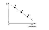
- the magnetic performance of the standard magnet 10 is defined by a combination of coercive force (Hcj) and residual magnetic flux density (Br), for example.
- Hcj coercive force
- Br residual magnetic flux density
- rare earth permanent magnets such as Nd—Fe—B are added with Dy, Tb, etc. in order to increase the coercive force.
- Dy, Tb, or the like when Dy, Tb, or the like is added, the coercive force (Hcj) increases as shown in FIG. 4, but the residual magnetic flux density (Br) decreases. Therefore, it is necessary to properly use permanent magnets having appropriate magnetic performance depending on applications (for example, for hybrid cars, air conditioners, hard disks, etc.) using permanent magnets.
- the plurality of types of standard magnets 10 having different magnetic performances have different colors for each type so that the user can distinguish them.
- the surface of the standard magnet 10 may be painted after sintering, or the standard magnet 10 is formed and sintered in a state in which a material that becomes a pigment is included in advance. It is good also as manufacturing.
- Dy, Tb, etc. As a method of adding Dy, Tb, etc., if Dy, Tb, etc. are unevenly arranged at the grain boundaries of the magnet, it is possible to improve the magnet performance while making the addition amount small. And as a method of unevenly arranging Dy, Tb, etc. at the grain boundaries of the magnet, for example, a grain boundary diffusion method in which Dy, Tb, etc. are attached to the surface of the sintered magnet and diffused, or the main phase and grain boundaries There are two alloy methods in which powders corresponding to phases are separately manufactured and mixed (dry blended), and a method in which an organometallic compound containing Dy, Tb, or the like is attached to the surface of magnet particles and then sintered. . Here, especially when adding Dy, Tb, etc.
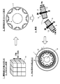
- the size of the standard magnet 10 can be set as appropriate. For example, as shown in FIG. 5, there are three types of cubes: a cube with a side of 4 mm, a cube with a side of 2 mm, and a cube with a side of 1 mm.
- the size of the standard magnet 10 may be two types or four or more types, and the shape can be arbitrarily set in addition to the size for each type. For example, you may prescribe
- the permanent magnet along the shape of the slot 9 can be obtained by combining the standard magnets 10 regardless of the shape of the slot 9. 4 can be formed. Further, as will be described later, it is possible to combine a plurality of types of standard magnets 10 having different sizes in the same permanent magnet 4.
- the standard magnet 10 is an anisotropic magnet, and the C-axis (easy magnetization axis) of the magnet crystal 13 is oriented in one direction by performing magnetic field orientation as described later. And when combining the standard magnet 10 and forming the permanent magnet 4, it combines so that the C-axis direction of each standard magnet 10 may become the same direction. After a plurality of standard magnets 10 are combined and accommodated in the slot 9, magnetization is performed by applying a magnetic field in parallel to the C-axis direction of each standard magnet 10. Thereby, the magnetic characteristics of the permanent magnet 4 can be greatly improved.
- the standard magnets 10 when combining a plurality of standard magnets 10 so that the C-axis directions are the same direction, the standard magnets 10 should be shaped so that the C-axis direction can be easily discriminated in order to facilitate the combination. desirable. Specifically, the standard magnet 10 is shaped differently in the C-axis direction and other axial directions.
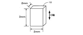
- the shape of the standard magnet 10 is a columnar shape (rectangular column, cylinder, etc.) with the C-axis direction as the height direction, and the length in the C-axis direction is the length in the other axial direction. If the shape is made longer (especially in the case of a rectangular parallelepiped, the length of the side in the C-axis direction is longer than the length of the other side), the C-axis direction of the standard magnet 10 can be easily determined. .
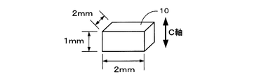
- the shape of the standard magnet 10 is a columnar shape (rectangular column, cylinder, etc.) with the C-axis direction as the height direction, and the length in the C-axis direction is the length in the other axial direction. If the shape is made shorter (especially in the case of a rectangular parallelepiped, the length of the side in the C-axis direction is shorter than the length of the other side), the C-axis direction of the standard magnet 10 can be easily determined. Become. 7 and 8, the standard magnet 10 is a rectangular parallelepiped, but it may be a cylinder, a hexagonal column, or the like. Further, as long as the C-axis direction can be discriminated, a spheroid (oblate, oblate) or the like may be used in addition to the columnar shape.
- a spheroid oblate, oblate
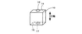
- the C-axis direction is not discriminated by the shape of the standard magnet 10 itself as shown in FIGS. 7 and 8, but the member serving as a mark is added to the standard magnet 10 as shown in FIG. It may be discriminated.
- the engaging portion 15 is formed on one surface 14 orthogonal to the C-axis direction of the standard magnet 10 and the engaged portion 15 is engaged with the engaging portion 15 on the other surface 16. 17 is formed.
- the engaging portion 15 is a convex member and the engaged portion 17 is a concave member.
- the shapes may be reversed or may be shapes that engage with each other. Other shapes may be used.
- a plurality of engaging portions 15 and engaged portions 17 may be formed on the surfaces 14 and 16. Furthermore, it is good also as a structure which forms the engaging part 15 or the to-be-engaged part 17 also about surfaces other than the surfaces 14 and 16 orthogonal to a C-axis direction. However, in that case, the shape and the number of installed portions 15 and engaged portions 17 formed on the surfaces 14 and 16 orthogonal to the C-axis direction so that the C-axis direction can be discriminated from other surfaces are different. It is desirable to make it.
- an insulating layer may be arranged at the boundary between adjacent standard magnets 10 when combined.
- the shaft 8 Need to rotate at high speed. And if it rotates at high speed, an eddy current will generate
- the permanent magnet 4 since the permanent magnet 4 is not integrally molded as described above, but is divided into a plurality of standard magnets 10, the size of eddy current generated inside the permanent magnet 4 is reduced. Even when the permanent magnet motor 1 is rotated at a high speed, it is possible to suppress an increase in the temperature of the permanent magnet. Further, if an insulating layer is arranged at the boundary between adjacent standard magnets 10, the eddy current path can be more reliably blocked by the insulating layer, and the scale of the eddy current generated inside the permanent magnet 4 can be reduced. .
- a method of arranging an insulating layer at the boundary between adjacent standard magnets 10 when combined for example, there is a method of coating the surface of each standard magnet 10 with an insulating layer in advance before combining the standard magnets 10.
- the insulating layer to be coated include ceramic and resin.
- the permanent magnet 4 is formed by combining the standard magnets 10
- a material for example, resin
- the standard magnets 10 are basically combined so that the C-axis directions of the standard magnets 10 are the same direction. good.
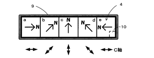
- the standard magnet 10 may be combined with a combination that allows the permanent magnet 4 to be anisotropically magnetized so as to satisfy the Halbach array.
- FIG. 12 is a diagram showing the permanent magnet 4 anisotropically magnetized so as to satisfy the Halbach array.
- the permanent magnet 4 is constituted by the adjacent areas a to e, and the standard magnet 10 is combined so that the C-axis direction is continuously changed for each area a to e. And is accommodated in the slot 9. Thereafter, the permanent magnet 4 satisfying the Halbach array is obtained by magnetizing the permanent magnet 4 along the C-axis direction of each area a to e so that the direction of the N pole (or S pole) is continuously changed. It can be configured.
- a resin, a long-chain hydrocarbon, a fatty acid methyl ester, a mixture thereof, or the like is used as the binder mixed with the magnet powder.
- a resin it is preferable to use a polymer that does not contain an oxygen atom in the structure and has a depolymerization property.
- a thermoplastic resin is used to perform magnetic field orientation in a state where the formed green sheet is heated and softened.
- the polymer which consists of 1 type, or 2 or more types of polymers or copolymers chosen from the monomer shown by the following general formula (1) corresponds.
- R1 and R2 represent a hydrogen atom, a lower alkyl group, a phenyl group or a vinyl group.
- polystyrene resin examples include polyisobutylene (PIB), which is a polymer of isobutylene, polyisoprene (isoprene rubber, IR), which is a polymer of isoprene, and polybutadiene (butadiene) that is a polymer of 1,3-butadiene.
- PIB polyisobutylene
- IR polyisoprene rubber
- IR isoprene rubber
- IR isoprene rubber
- butadiene butadiene
- Rubber, BR polystyrene as a polymer of styrene, styrene-isoprene block copolymer (SIS) as a copolymer of styrene and isoprene, butyl rubber (IIR) as a copolymer of isobutylene and isoprene, styrene and butadiene
- SIS styrene-isoprene block copolymer
- IIR butyl rubber
- SBS styrene-butadiene block copolymer which is a copolymer of 2-methyl-1-pentene, a polymer of 2-methyl-1-pentene, and a polymer of 2-methyl-1-butene.
- a 2-methyl-1-butene polymer resin a polymer of ⁇ -methylstyrene That there is ⁇ - methyl styrene polymer resin.
- the resin used for the binder may include a small amount of a polymer or copolymer of a monomer containing an oxygen atom (for example, polybutyl methacrylate, polymethyl methacrylate, etc.).
- a monomer that does not correspond to the general formula (1) may be partially copolymerized. Even in that case, it is possible to achieve the object of the present invention.
- thermoplastic resin that softens at 250 ° C. or lower, more specifically a thermoplastic resin having a glass transition point or a melting point of 250 ° C. or lower in order to appropriately perform magnetic field orientation. .
- a long chain hydrocarbon when used for the binder, it is preferable to use a long chain saturated hydrocarbon (long chain alkane) that is solid at room temperature and liquid at room temperature or higher. Specifically, it is preferable to use a long-chain saturated hydrocarbon having 18 or more carbon atoms.
- molding so that it may mention later is magnetic field orientation
- magnetic field orientation is performed in the state which heated the green sheet above melting
- fatty acid methyl ester when used as the binder, it is preferable to use methyl stearate or methyl docosanoate which is solid at room temperature and liquid at room temperature or higher.
- methyl stearate or methyl docosanoate which is solid at room temperature and liquid at room temperature or higher.
- magnetic field orientation magnetic field orientation is performed in the state which heated the green sheet above melting
- the amount of carbon and oxygen contained in the magnet can be reduced.
- the amount of carbon remaining in the magnet after sintering is 2000 ppm or less, more preferably 1000 ppm or less.
- the amount of oxygen remaining in the magnet after sintering is set to 5000 ppm or less, more preferably 2000 ppm or less.
- the amount of the binder added is an amount that appropriately fills the gaps between the magnet particles in order to improve the thickness accuracy of the sheet when the slurry or the heated and melted compound is formed into a sheet.
- the ratio of the binder to the total amount of magnet powder and binder is 1 wt% to 40 wt%, more preferably 2 wt% to 30 wt%, and even more preferably 3 wt% to 20 wt%.
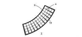
- FIG. 13 is an overall view showing the permanent magnet 4 according to the present invention and the slot 9 in which the permanent magnet 4 is accommodated.
- the permanent magnet 4 according to the present invention is formed by combining a plurality of standard magnets 10 having a predetermined standard shape as described above.
- the slot 9 is designed to have a shape corresponding to the shape of the permanent magnet 4 in which a plurality of standard magnets 10 are combined.
- the slot 9 is The shape is made to correspond to the rectangular parallelepiped shape.
- a rectangular parallelepiped shape for example, 22 mm ⁇ 8.5 mm ⁇ 51 mm
- a predetermined grace distance for example, 0.5 to 3 mm
- the slot 9 is not necessarily a rectangular parallelepiped shape, and may be a cylindrical shape or the like.
- the shape of the slot 9 may be a shape having a fan-shaped cross section with respect to the accommodation direction of the standard magnet. And when accommodating the permanent magnet 4 with respect to the slot 9 which has a fan shape as shown in FIG. 15, when combining the standard magnet 10, the positional relationship of adjacent standard magnets 10 is according to a fan shape. Set. Accordingly, the permanent magnet 4 can be appropriately accommodated even in the slot 9 that draws a curved shape such as a fan shape. On the other hand, when an integrally molded permanent magnet is to be accommodated in a slot 9 having a fan shape as shown in FIG. 15, the permanent magnet must be processed into a complicated shape such as a fan shape. However, there is a problem that the manufacturing process becomes very complicated.
- the shape of the outer edge portion forming the slot 9 may be a shape corresponding to the shape of the standard magnet 10.
- the shape of the outer edge forming the slot 9 corresponds to the shape of the standard magnet 10 ( Step shape).
- the magnetic flux density does not change uniformly with respect to the standard magnet 10 accommodated in the slot 9, but a large magnetic flux density change occurs at a specific location.
- the slot 9 is arranged so as to have a substantially square shape along the axial direction of the rotor core 7 as shown in FIG. 1, the vicinity of the center of the paired permanent magnets 4 as shown in FIG. A particularly large change in magnetic flux density occurs at the corners. That is, there is a high possibility that a strong eddy current is generated at the same location, while there is a low possibility that a strong eddy current is generated at other locations.
- the standard magnets 10 having a particularly high coercive force are arranged only at locations where the change in magnetic flux density is large in the permanent magnet motor 1. If this is done, the amount of Dy or Tb used can be reduced in a state where the permanent magnet 4 retains its function as a magnet (that is, a state in which a coercive force equal to or higher than the reverse magnetic field can be maintained even if the temperature rises due to eddy current). This makes it possible to reduce manufacturing costs. For example, as shown in FIG. 18, the standard magnet 10 having a higher coercive force than other locations can be combined and housed at locations where the change in magnetic flux density is large.
- the standard magnets 10 having a high coercive force can be accommodated in combination so as to be arranged step by step as approaching a location where the change in magnetic flux density is large.
- the standard magnet 10 located outside the standard magnet 10 located inside is a standard magnet 10 having a higher coercive force.
- two types of standard magnets 10 having different coercive forces are combined in the inner and outer sections, but may be divided into three or more stages. As long as the standard magnet 10 having a high coercive force is disposed at a location where the change in magnetic flux density is large in the permanent magnet motor 1, combinations other than those shown in FIGS. 18 to 20 may be used.
- the standard magnets 10 constituting the permanent magnet 4 are not all combined with the standard magnets 10 of the same size, but the standard magnets 10 having a particularly small size are arranged only at locations where the change in the magnetic flux density is large in the permanent magnet motor 1. Then, the scale of the eddy current generated in the permanent magnet 4 can be further reduced without particularly reducing the productivity of the permanent magnet 4.
- the standard magnets 10 having a smaller size than other portions can be combined and housed at a location where the change in magnetic flux density is large.
- the standard magnets 10 whose size is gradually reduced can be combined and housed as they approach a location where the change in magnetic flux density is large. Furthermore, as shown in FIG.
- the standard magnet 10 positioned outside the standard magnet 10 positioned inside may be combined so that the standard magnet 10 having a smaller size is obtained.
- the standard magnets 10 of two types of sizes are combined in the inner and outer sections, but may be divided into three or more stages. As long as the standard magnet 10 having a small size is arranged at a location where the change in the magnetic flux density is large in the permanent magnet motor 1, combinations other than those shown in FIGS. 21 to 23 may be used.
- FIG. 24 is an explanatory view showing a manufacturing process until the standard magnet 10 is manufactured.
- an ingot made of a predetermined fraction of Nd—Fe—B (eg, Nd: 32.7 wt%, Fe (electrolytic iron): 65.96 wt%, B: 1.34 wt%) is manufactured. Thereafter, the ingot is roughly pulverized to a size of about 200 ⁇ m by a stamp mill or a crusher. Alternatively, the ingot is melted, flakes are produced by strip casting, and coarsely pulverized by hydrogen crushing. Thereby, coarsely pulverized magnet powder 30 is obtained.
- Nd—Fe—B eg, Nd: 32.7 wt%, Fe (electrolytic iron): 65.96 wt%, B: 1.34 wt%
- the coarsely pulverized magnet powder 30 is finely pulverized by a wet method using a bead mill 31 or a dry method using a jet mill.
- the coarsely pulverized magnet powder 30 is finely pulverized in an organic solvent to a predetermined particle size (for example, 0.1 ⁇ m to 5.0 ⁇ m), and the magnet powder is dispersed in the organic solvent. Disperse. Thereafter, the magnet powder contained in the organic solvent after the wet pulverization is dried by vacuum drying or the like, and the dried magnet powder is taken out.
- the solvent used for the pulverization is an organic solvent, but the type of the solvent is not particularly limited, alcohols such as isopropyl alcohol, ethanol and methanol, esters such as ethyl acetate, lower hydrocarbons such as pentane and hexane, Aromatics such as benzene, toluene and xylene, ketones, mixtures thereof and the like can be used.
- a hydrocarbon solvent that does not contain an oxygen atom in the solvent is used.
- coarsely pulverized magnet powder is (a) in an atmosphere composed of an inert gas such as nitrogen gas, Ar gas, and He gas having substantially 0% oxygen content.
- the oxygen concentration of substantially 0% is not limited to the case where the oxygen concentration is completely 0%, but may contain oxygen in such an amount that a very small amount of oxide film is formed on the surface of the fine powder. Means good.
- the magnet powder finely pulverized by the bead mill 31 or the like is molded into a desired shape.
- the molding of the magnet powder includes, for example, compaction molding that forms a desired shape using a mold and green sheet molding in which the magnet powder is once formed into a sheet shape and then punched into the desired shape.
- compaction molding that forms a desired shape using a mold and green sheet molding in which the magnet powder is once formed into a sheet shape and then punched into the desired shape.
- green sheet molding for example, hot melt coating for molding a compound in which magnet powder and a binder are mixed into a sheet, or slurry containing magnet powder, a binder, and an organic solvent is coated on a substrate. There is molding by slurry coating or the like to form a sheet.
- a powdery mixture (compound) 32 composed of magnet powder and binder is prepared by mixing a binder with magnet powder.
- the binder resin, long chain hydrocarbon, fatty acid methyl ester, a mixture thereof, or the like is used as described above.
- a resin a thermoplastic resin made of a depolymerizable polymer that does not contain an oxygen atom in the structure is used.
- a long-chain hydrocarbon the resin is solid at room temperature or above room temperature. It is preferable to use a long-chain saturated hydrocarbon (long-chain alkane) that is liquid.
- the amount of the binder added is such that the ratio of the binder to the total amount of the magnet powder and the binder in the compound 12 after the addition is 1 wt% to 40 wt%, more preferably 2 wt% to 30 wt%, still more preferably 3 wt%. % To 20 wt%.
- the binder is added in an atmosphere made of an inert gas such as nitrogen gas, Ar gas, or He gas.
- the mixing of the magnet powder and the binder is performed, for example, by putting the magnet powder and the binder in an organic solvent and stirring with a stirrer.
- the compound 12 is extracted by heating the organic solvent containing magnet powder and a binder after stirring, and vaporizing an organic solvent.
- the mixing of the magnet powder and the binder is preferably performed in an atmosphere made of an inert gas such as nitrogen gas, Ar gas, or He gas.
- an inert gas such as nitrogen gas, Ar gas, or He gas.
- the binder is added to the organic solvent and kneaded without taking out the magnet powder from the organic solvent used for pulverization, and then the organic solvent is volatilized to be described later. It is good also as a structure which obtains the compound 12.
- a green sheet is created by forming the compound 32 into a sheet shape.
- the compound 32 in the hot melt coating, the compound 32 is heated to melt the compound 32 to be in a fluid state, and then applied onto the support substrate 33 such as a separator. Then, the long sheet-like green sheet 34 is formed on the support base material 33 by heat radiation and solidifying.
- the temperature at which the compound 32 is heated and melted is 50 to 300 ° C., although it varies depending on the kind and amount of the binder used. However, the temperature needs to be higher than the melting point of the binder to be used.
- magnet powder and a binder are disperse
- the coating method of the melted compound 32 it is preferable to use a method having excellent layer thickness controllability such as a slot die method and a calendar roll method.
- a method having excellent layer thickness controllability such as a slot die method and a calendar roll method.
- the slot die method coating is performed by extruding a heated compound 32 in a fluid state by a gear pump and inserting the compound 32 into a die.
- the calendar roll method a certain amount of the compound 32 is charged into the gap between the two heated rolls, and the compound 32 melted by the heat of the roll is applied onto the support substrate 33 while rotating the roll.
- a silicone-treated polyester film is used as the support base material 33.
- the film is formed on the support substrate 33 by forming the compound 32 melted by extrusion molding into a sheet shape and extruding the support substrate 33 instead of coating on the support substrate 33. It is good also as composition to do.
- FIG. 25 is a schematic view showing a process of forming the green sheet 34 by the slot die method.
- the die 35 used in the slot die system is formed by overlapping blocks 36 and 37, and a slit 38 and a cavity (liquid reservoir) 39 are formed by a gap between the blocks 36 and 37.
- the cavity 39 communicates with a supply port 40 provided in the block 37.
- the supply port 40 is connected to a coating liquid supply system constituted by a gear pump (not shown) or the like, and the measured fluid-like compound 32 is quantified in the cavity 39 via the supply port 40. Supplied by a pump or the like.
- the fluid compound 32 supplied to the cavity 39 is fed to the slit 38 and discharged from the discharge port 41 of the slit 38 with a predetermined application width with a uniform amount in the width direction at a constant amount per unit time.
- the support base material 33 is continuously conveyed at a preset speed with the rotation of the coating roll 42.
- the ejected fluid compound 32 is applied to the support base material 33 at a predetermined thickness, and then heat radiation and solidification are performed to form a long sheet-like green sheet 34 on the support base material 33. Is done.
- the sheet thickness of the green sheet 34 after coating is measured, and the gap D between the die 35 and the support base material 33 is feedback-controlled based on the measured value. desirable. Further, the fluctuation of the amount of the fluid compound 32 supplied to the die 35 is reduced as much as possible (for example, suppressed to fluctuation of ⁇ 0.1% or less), and the fluctuation of the coating speed is further reduced as much as possible (for example, ⁇ 0. It is desirable to suppress the fluctuation to 1% or less. Thereby, the thickness accuracy of the green sheet 34 can be further improved.
- the thickness accuracy of the formed green sheet 34 is within ⁇ 10%, more preferably within ⁇ 3%, and even more preferably within ⁇ 1% with respect to the design value (for example, 2 mm).
- the transfer film thickness of the compound 32 to the support base material 33 can be controlled by similarly controlling the calendar conditions based on the actually measured values.
- the set thickness of the green sheet 34 is desirably set in the range of 0.05 mm to 20 mm. When the thickness is less than 0.05 mm, the productivity must be reduced because multiple layers must be stacked.
- a green sheet that has been divided into the standard shape of the standard magnet 10 in advance may be formed.
- a molding frame 44 in which a plurality of standard-shaped molds 43 as shown in FIG. 26 are formed in parallel is placed on the support base material 33, and a slurry in which magnet powder and a binder are mixed or a melted compound is used.
- a green sheet is formed by coating from above the forming frame 44.
- the green magnet can be formed into the standard magnet 10 without performing punching into a standard shape as described later by removing the green sheet from the molding frame 44 after the magnetic field orientation.
- the magnetic orientation of the green sheet 34 formed on the support base material 33 by the hot melt coating described above is performed.
- the green sheet 34 is first softened by heating the green sheet 34 that is continuously conveyed together with the support base material 33.
- the temperature and time for heating the green sheet 34 vary depending on the type and amount of the binder used, but are, for example, 100 to 250 ° C. and 0.1 to 60 minutes. However, in order to soften the green sheet 34, the glass transition point of the binder to be used or a temperature higher than the melting point is required.
- a heating method for heating the green sheet 34 for example, there are a heating method using a hot plate and a heating method using a heat medium (silicone oil) as a heat source.
- magnetic field orientation is performed by applying a magnetic field to the in-plane direction and the length direction of the green sheet 34 softened by heating.
- the intensity of the applied magnetic field is 5000 [Oe] to 150,000 [Oe], preferably 10,000 [Oe] to 120,000 [Oe].
- the C-axis (easy magnetization axis) of the magnet crystal included in the green sheet 34 is oriented in one direction.
- the magnetic field may be applied in the in-plane direction and the width direction of the green sheet 34. Moreover, it is good also as a structure which orientates a magnetic field simultaneously with respect to the some green sheet 34.
- a configuration in which a magnetic field is applied at the same time as the heating process may be performed, or a magnetic field may be applied after the heating process and before the green sheet solidifies. It is good also as performing the process to perform. Moreover, it is good also as a structure which magnetic field orientates before the green sheet 34 coated by hot-melt coating solidifies. In that case, the heating step is not necessary.
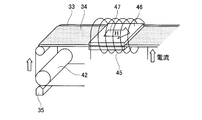
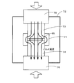
- FIG. 27 is a schematic diagram showing a heating process and a magnetic field orientation process of the green sheet 34.
- FIG. 27 an example in which the magnetic field orientation process is performed simultaneously with the heating process will be described.
- heating and magnetic field orientation on the green sheet 34 coated by the above-described slot die method are performed on the long sheet-like green sheet 34 that is continuously conveyed by a roll. That is, an apparatus for performing heating and magnetic field orientation is disposed on the downstream side of the coating apparatus (die or the like), and is performed by a process continuous with the above-described coating process.
- the solenoid 45 is disposed on the downstream side of the die 35 and the coating roll 42 so that the support base material 33 and the green sheet 34 to be conveyed pass through the solenoid 45. Further, the hot plates 46 are arranged in a pair above and below the green sheet 34 in the solenoid 45. Then, the green sheet 34 is heated by a pair of upper and lower hot plates 46 and a current is passed through the solenoid 45 so that the in-plane direction of the long green sheet 34 (that is, the sheet surface of the green sheet 34). A magnetic field in the longitudinal direction).
- the continuously conveyed green sheet 34 is softened by heating, and a magnetic field is applied to the in-plane direction and the length direction of the softened green sheet 34 (in the direction of arrow 47 in FIG. 27).
- a magnetic field is applied to the in-plane direction and the length direction of the softened green sheet 34 (in the direction of arrow 47 in FIG. 27).
- the surface of the green sheet 34 can be prevented from standing upright by setting the direction in which the magnetic field is applied to the in-plane direction.
- a pair of magnetic field coils are arranged on the left and right sides of the green sheet 34 conveyed instead of the solenoid 45. Then, by supplying a current to each magnetic field coil, it is possible to generate a magnetic field in the in-plane direction and the width direction of the long sheet-like green sheet 34.
- the magnetic field orientation can be set to the in-plane vertical direction of the green sheet 34.
- the magnetic field application device using a pole piece or the like is used.
- a magnetic field application device 50 using a pole piece or the like includes two ring-shaped coil portions 51 and 52 arranged in parallel so that the central axes are the same, and the coil portion 51. , 52 and two substantially cylindrical pole pieces 53 and 54 respectively disposed in the ring holes, and are spaced apart from the conveyed green sheet 34 by a predetermined distance.
- the magnetic field orientation direction is the in-plane vertical direction of the green sheet 34
- a film 55 is laminated on the opposite side of the green sheet 34 on which the support base material 33 is laminated as shown in FIG. It is preferable to do. Thereby, it is possible to prevent the surface of the green sheet 34 from standing upside down.
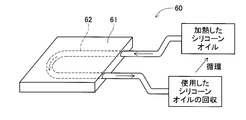
- FIG. 29 is a diagram showing an example of a heating device 60 using a heat medium.
- the heating device 60 forms a substantially U-shaped cavity 62 inside a flat plate member 61 serving as a heating element, and heat heated to a predetermined temperature (for example, 100 to 300 ° C.) in the cavity 62. It is set as the structure which circulates the silicone oil which is a medium.
- the heating device 60 is arranged in a pair above and below the green sheet 34 in the solenoid 45.
- the continuously conveyed green sheet 34 is heated and softened through the flat plate member 61 generated by the heat medium.
- the flat plate member 61 may be brought into contact with the green sheet 34 or may be arranged at a predetermined interval.
- a magnetic field is applied to the in-plane direction and the length direction (in the direction of arrow 47 in FIG. 27) of the green sheet 34 by the solenoid 45 arranged around the softened green sheet 34, An appropriate uniform magnetic field can be oriented.
- the heating device 60 using the heat medium as shown in FIG. 29 does not have a heating wire inside unlike a general hot plate 46, so even if it is placed in a magnetic field, There is no possibility that the heating wire vibrates or is cut, and the green sheet 34 can be appropriately heated.
- the heating device 60 using a heat medium as the heat source, Such a problem can be solved.
- the green sheet 34 is formed from a liquid material having high fluidity such as slurry by a general slot die method or doctor blade method without using hot melt molding, a magnetic field gradient is generated.
- the magnetic powder contained in the green sheet 34 is attracted toward the stronger magnetic field, and the liquid of the slurry forming the green sheet 34, that is, the thickness of the green sheet 34 is uneven. May occur.
- the compound 32 is molded into the green sheet 34 by hot melt molding as in the present invention, the viscosity near room temperature reaches several tens of thousands Pa ⁇ s, and the magnetic powder tends to shift when passing through the magnetic field gradient. It does not occur.
- the viscosity of the binder is lowered by being transported and heated in a uniform magnetic field, and uniform C-axis orientation is possible only by the rotational torque in the uniform magnetic field.
- the thickness exceeds 1 mm.
- foaming due to vaporization of the organic solvent contained in the slurry or the like at the time of drying becomes a problem.
- the drying time is prolonged to suppress foaming, the magnet powder is settled, and accordingly, the density distribution of the magnet powder is biased with respect to the direction of gravity, which causes warping after firing. Therefore, in the molding from the slurry, the upper limit value of the thickness is substantially regulated, so it is necessary to mold the green sheet with a thickness of 1 mm or less and then laminate it.
- the green sheet 34 subjected to magnetic field orientation is punched into a desired standard shape (for example, a rectangular parallelepiped shape shown in FIGS. 7 to 9), and a molded body 65 is formed.
- a desired standard shape for example, a rectangular parallelepiped shape shown in FIGS. 7 to 9
- a non-oxidizing atmosphere (particularly a hydrogen atmosphere or hydrogen in the present invention) in which the molded body 65 is pressurized to atmospheric pressure, or a pressure higher or lower than atmospheric pressure (for example, 1.0 Pa or 1.0 MPa).
- an inert gas mixed gas atmosphere at a binder decomposition temperature for several hours (for example, 5 hours) to perform a calcination treatment.
- the supply amount of hydrogen during calcination is set to 5 L / min.
- decarbonization for reducing the amount of carbon in the molded body 65 is performed.
- the calcining treatment is performed under the condition that the carbon content in the molded body 65 is 2000 ppm or less, more preferably 1000 ppm or less. Accordingly, the entire permanent magnet can be densely sintered by the subsequent sintering process, and the residual magnetic flux density and coercive force are not reduced.
- the binder decomposition temperature is determined based on the analysis results of the binder decomposition product and decomposition residue. Specifically, a temperature range is selected in which decomposition products of the binder are collected, decomposition products other than the monomers are not generated, and products due to side reactions of the remaining binder components are not detected even in the analysis of the residues. Although it varies depending on the type of the binder, it is set to 200 ° C. to 900 ° C., more preferably 400 ° C. to 600 ° C. (eg 600 ° C.).
- the calcining treatment is performed at the thermal decomposition temperature and binder decomposition temperature of the organic compound constituting the organic solvent. Thereby, the remaining organic solvent can be removed.
- the thermal decomposition temperature of the organic compound is determined depending on the type of the organic solvent to be used, but basically the thermal decomposition of the organic compound can be performed at the binder decomposition temperature.
- NdH 3 (high activity) in the molded body 65 produced by the calcination treatment is changed stepwise from NdH 3 (high activity) ⁇ NdH 2 (low activity).
- the activity of the molded body 65 activated by the calcination treatment is reduced.
- the sintering process which sinters the molded object 65 calcined by the calcining process is performed.
- a sintering method of the molded body 65 it is possible to use pressure sintering which sinters in a state where the molded body 65 is pressed in addition to general vacuum sintering.
- the temperature is raised to a firing temperature of about 800 ° C. to 1080 ° C. at a predetermined temperature increase rate and held for about 0.1 to 2 hours.
- vacuum firing is performed, but the degree of vacuum is preferably 5 Pa or less, and preferably 10 ⁇ 2 Pa or less.
- it is cooled and heat-treated again at 300 ° C. to 1000 ° C. for 2 hours.
- the standard magnet 10 is manufactured.
- pressure sintering examples include hot press sintering, hot isostatic pressing (HIP) sintering, ultrahigh pressure synthetic sintering, gas pressure sintering, and discharge plasma (SPS) sintering.
- HIP hot isostatic pressing
- SPS discharge plasma
- the SPS is uniaxial pressure sintering that pressurizes in a uniaxial direction and is sintered by current sintering. Sintering is preferably used.
- the pressure value is set to, for example, 0.01 MPa to 100 MPa, the pressure is increased to 940 ° C.
- the standard magnet 10 is manufactured.
- FIG. 30 is an explanatory view showing a pressure sintering process of the molded body 65 by SPS sintering.
- a compact 65 is placed on a graphite sintering die 71.
- the calcination treatment described above may also be performed in a state where the molded body 65 is installed in the sintering mold 71.
- the compact 65 installed in the sintering die 71 is held in the vacuum champ 72, and an upper punch 73 and a lower punch 74 made of graphite are also set.
- the molded body 65 installed in the sintering die 71 is sintered while being pressurized.
- FIG. 31 is an explanatory view showing a manufacturing process until the permanent magnet motor 1 is manufactured using the standard magnet 10.
- the permanent magnet 4 is formed by combining a plurality of standard magnets 10 manufactured by the manufacturing process shown in FIG. Note that the step of combining the standard magnet 10 and the step of accommodating the standard magnet 10 may be performed simultaneously, or the step of combining the standard magnet 10 first and then the step of accommodating the standard magnet 10 may be performed. Further, the standard magnet 10 before being combined may be lightly magnetized (first stage magnetization). As a result, the standard magnets 10 can be easily combined. Then, after the lightly magnetized standard magnet 10 is accommodated in the slot 9, final magnetization (second stage magnetization) may be performed.
- the process of combining the standard magnets 10 is performed first, the plurality of standard magnets 10 combined are fixed in a state corresponding to the slot 9 by combining a plurality of standard magnets 10.
- a plurality of standard magnets 10 are accommodated in the slots 9.
- the standard magnet 10 is sequentially accommodated in the slot 9 to be combined into a shape corresponding to the slot 9. In that case, it is not always necessary to fix the combined standard magnets 10 together.
- the standard magnet 10 when combining the standard magnet 10, it combines so that the C-axis direction of each standard magnet 10 may become the same direction. Further, as will be described later, in the present invention, magnetization is performed by applying a magnetic field parallel to the C-axis direction of each standard magnet 10. Therefore, it is necessary to combine the standard magnets 10 in consideration of the magnetization direction and accommodate them in the slots 9. Specifically, the standard magnets 10 are combined and accommodated in the slot 9 so that the radial direction of the rotor core 7 and the C-axis direction of the standard magnet 10 coincide. However, as described above, when the permanent magnets 4 are magnetized in the Halbach array, the C-axis directions of the standard magnets 10 are continuously changed and combined and accommodated in the slot 9 (see FIG. 12).
- the permanent magnet 4 accommodated in the slot 9 is fixed to the slot 9 by filling the slot 9 with the filler 11.
- magnetization is performed by applying a magnetic field to the permanent magnet 4 accommodated in the slot 9.
- the pair of permanent magnets 4 are magnetized so that the polarities on the rotor outer peripheral side are the same, and the adjacent pairs have different polarities. Magnetize like so. That is, as shown in FIG. 31, in the rotor core 7 in which a total of 16 permanent magnets 4 are accommodated in 8 pairs, 8 magnetic poles are constituted by 8 pairs of permanent magnets 4. Then, N poles and S poles are alternately arranged along the circumferential direction of the rotor core 7.
- the standard magnets 10 are combined and accommodated in the slots 9 so that the radial direction of the rotor core 7 and the C-axis direction of the standard magnets 10 coincide with each other, so that they are parallel to the C-axis direction of each standard magnet 10.
- a magnetic field is applied.
- the permanent magnet 4 is magnetized in the Halbach arrangement as described above, the permanent magnet 4 is magnetized so that the direction of the N pole (or S pole) is continuously changed (see FIG. 12).
- a magnetizing coil, a magnetizing yoke, a condenser magnetizing power supply device, or the like is used for magnetizing the permanent magnet 4, for example, a magnetizing coil, a magnetizing yoke, a condenser magnetizing power supply device, or the like is used.
- the permanent magnet motor 1 is manufactured by assembling members other than the rotor core 7 such as the shaft 8 and the stator 2.
- the permanent magnet 4 accommodated in the slot 9 formed in the rotor core 7 of the permanent magnet motor 1 is formed into a predetermined standard shape.
- the standard magnet 10 is a permanent magnet having a plurality of standard magnets, and the slot 9 is designed to have a shape corresponding to a combination of a plurality of standard magnets 10. It becomes possible to form permanent magnets 4 corresponding to various types of permanent magnet motors 1 by combination. As a result, it is not necessary to manufacture the permanent magnet 4 having a different shape for each permanent magnet motor, so that the manufacturing efficiency can be dramatically increased.
- the permanent magnet 4 having a complicated shape by changing the combination of the standard magnets 10 as compared with the case of using an integrally molded permanent magnet.
- the type of standard magnets 10 to be combined is changed depending on applications (for example, for hybrid cars, for air conditioning, and for hard disks). By this, it becomes possible to form the permanent magnet 4 which has the magnetic performance according to a use.
- the permanent magnet 4 retains its function as a magnet (ie, the temperature due to the eddy current). Even in the case where the coercive force is higher than the reverse magnetic field), the amount of Dy and Tb used can be reduced, and the manufacturing cost can be reduced. Further, when the standard magnet 10 is combined, if the standard magnet 10 positioned on the outer side is combined with the standard magnet 10 having a higher coercive force than the standard magnet 10 positioned on the inner side, the permanent magnet 4 is used.
- the standard magnet 10 can reduce the amount of Dy and Tb used and the manufacturing cost while maintaining the function as a magnet (that is, a state in which a coercive force higher than the reverse magnetic field can be maintained even if the temperature rises due to eddy current). Become. Moreover, since the standard magnet 10 has a different color for each magnetic performance, even if there are a plurality of types of standard magnets 10 having different magnetic performance, the user can easily determine the magnetic performance of the standard magnet 10 from the appearance. It becomes. Further, since there are a plurality of types of standard magnets 10 having different sizes, the standard magnet 10 can be formed in any shape by changing the size of the standard magnet 10 to be combined with the shape of the slot 9.
- the combination of 10 makes it possible to form the permanent magnet 4 along the shape of the housing portion. If the standard magnet 10 having a smaller size is disposed in a location where the change in the magnetic flux density is larger in the permanent magnet motor 1, the permanent magnet 4 is generated without particularly reducing the productivity of the permanent magnet 4. The scale of eddy current can be further reduced. Further, when the standard magnet 10 is combined, if the standard magnet 10 positioned on the outer side is combined with the standard magnet 10 having a smaller size than the standard magnet 10 positioned on the inner side, the permanent magnet 4 is used. The size of the eddy current generated in the permanent magnet 4 can be further reduced without particularly reducing the productivity.
- the standard magnet 10 is an anisotropic magnet, and a plurality of standard magnets 10 are combined and accommodated in the slot 9 so that the C-axis direction (magnetization easy axis) of each standard magnet 10 is the same direction.
- the magnetic performance of the permanent magnet 4 is greatly improved when magnetization is performed, compared to the case where an isotropic magnet is used or an anisotropic magnet is used and the C-axis direction is not combined in the same direction. It becomes possible.
- a plurality of standard magnets 10 are combined and accommodated in the slot 9, and a magnetic field is applied parallel to the C-axis direction of each standard magnet 10, magnetization is performed. Therefore, the permanent magnet 4 accommodated in the slot 9 is divided into a plurality of parts.
- the magnetic performance of the permanent magnet 4 can be greatly improved as in the case of using an integrally formed anisotropic magnet.
- the standard magnet 10 since the standard magnet 10 has different shapes in the C-axis direction and other axial directions, the C-axis direction of the standard magnet 10 can be easily distinguished from the external shape. As a result, even when the standard magnets 10 are combined so that the C-axis directions are the same, the combination work can be easily performed.
- the standard magnet 10 has a shape in which the length in the C-axis direction is shorter or longer than the length in the other axial directions, the C-axis direction of the standard magnet 10 can be easily distinguished from the appearance shape.
- the standard magnet 10 has a columnar shape with the C-axis direction as a height, the standard magnet 10 can be easily combined. Further, since the length in the C-axis direction is shorter or longer than the length in the other axial directions, the C-axis direction of the standard magnet 10 can be easily determined from the external shape. Further, since the standard magnet 10 is a rectangular parallelepiped and has a shape in which the length of the side in the C-axis direction is shorter or longer than the length of the other side, the C-axis direction of the standard magnet 10 can be easily determined from the appearance shape. Is possible.
- the engaging portion 15 is formed on one surface orthogonal to the C-axis direction of the standard magnet 10 and the engaged portion 17 that engages with the engaging portion 15 is formed on the other surface, the engaging portion It becomes possible to easily determine the C-axis direction of the standard magnet 10 using the 15 and the engaged portion 17 as a mark. Further, by engaging the engaging portion 15 and the engaged portion 17, it is possible to easily combine the plurality of standard magnets 10.
- the insulating layer 20 is formed at the boundary between the adjacent standard magnets 10 when combined, the eddy current generated in the permanent magnet 4 is reduced even when the permanent magnet motor 1 is rotated at a high speed. be able to. Therefore, it is possible to prevent a temperature increase and a decrease in coercive force of the permanent magnet 4 and provide a high-power small motor. Further, since the insulating layer 20 is formed with respect to the boundary parallel to the direction of the magnetic field generated in the permanent magnet motor 1, the effect of preventing eddy currents can be achieved while minimizing the location where the insulating layer 20 is formed. Is possible.
- the shape of the outer edge portion forming the slot 9 is a shape corresponding to the shape of the standard magnet 10 constituting the permanent magnet 4, the shape of the slot 9 or the standard magnet 10 is a special shape.
- the standard magnet 10 can be appropriately accommodated in the slot 9 and fixed.
- the standard magnet 10 can be appropriately accommodated in the slot 9 and fixed.
- the slot 9 has a fan-shaped cross section with respect to the accommodation direction of the standard magnet 10 and the standard magnets 10 are combined, the positional relationship between the adjacent standard magnets 10 is set according to the sector shape.
- the permanent magnet 4 can be shaped to correspond to the slot 9 by the combination of the standard magnets 10. Further, in a state where a plurality of standard magnets 10 are combined to form a shape corresponding to the slot 9, the combined plurality of standard magnets 10 are fixed to each other, and then the plurality of standard magnets 10 fixed are accommodated in the slot 9. As a result, even if the permanent magnet 4 is divided into a plurality of standard magnets 10, the standard magnet 10 can be easily accommodated in the slot 9.
- the standard magnets 10 that are adjacent to each other when they are combined are fixed to each other via an insulating layer disposed at the boundary, the standard magnets 10 can be appropriately fixed without deteriorating the magnetic properties.
- the eddy current generated in the permanent magnet 4 can be reduced. Therefore, it is possible to prevent a temperature increase and a decrease in coercive force of the permanent magnet 4 and provide a high-power small motor.
- the plurality of standard magnets 10 are sequentially accommodated in the slot 9 and combined with the shape corresponding to the slot 9, even if the permanent magnet 4 is divided into the plurality of standard magnets 10, the standard magnet 10. Can be appropriately taken into the slot 9.
- the process of combining the standard magnets 10 and the process of housing in the slot 9 can be performed simultaneously, the manufacturing process can be simplified.
- the first stage of magnetization is performed in advance before combining the standard magnets 10, the standard magnets 10 can be easily combined.
- the slot 9 for accommodating the permanent magnet 4 is formed along the axial direction of the rotor core 7, a permanent magnet embedded type motor such as an IPM motor used in a hybrid vehicle, an electric vehicle or the like is manufactured. Efficiency can be dramatically increased.
- the plurality of standard magnets 10 accommodated in the slot 9 are fixed to the slot 9 by filling the slot 9 with the filler 11, the permanent magnet 4 is divided by the plurality of standard magnets 10.
- each standard magnet 10 can be appropriately fixed to the slot 9.
- the standard magnet is composed of a magnet obtained by mixing magnet powder and a binder and sintering the formed green sheet 34, deformation due to sintering becomes uniform, and deformation such as warping and dent after sintering can be obtained. It does not occur, and pressure unevenness during pressing is eliminated, so that it is not necessary to carry out correction processing after sintering, which has been conventionally performed, and the manufacturing process can be simplified.
- a standard magnet having a predetermined standard shape can be formed with high dimensional accuracy. Further, even when the standard magnet has a minute shape, it is possible to prevent an increase in the number of processing steps without reducing the material yield.
- the standard magnet 10 is an Nd-based rare earth magnet
- the permanent magnets 4 can be arranged in a Halbach array. In that case, the C-axis direction (easy magnetization axis) of each standard magnet 10 is continuously changed so that the plurality of standard magnets 10 combined and accommodated in the slot 9 are magnetized in the Halbach array. combine. Accordingly, the combined standard magnets 10 (that is, the permanent magnets 4) can be arranged in a Halbach array. As a result, a stronger magnetic field can be generated.
- the pulverization conditions, kneading conditions, calcination conditions, sintering conditions, and the like of the magnet powder when manufacturing the standard magnet 10 are not limited to the conditions described in the above embodiments.
- the magnet raw material is pulverized by dry pulverization using a jet mill, but may be pulverized by wet pulverization using a bead mill.
- the green sheet is formed by the slot die method, but other methods (for example, calendar roll method, comma coating method, extrusion molding, injection molding, mold molding, doctor blade method, etc.) can be used. It may be used to form a green sheet. Moreover, it is good also as producing a green sheet by producing
- a hydrogen atmosphere for example, a nitrogen atmosphere, a He atmosphere, or an Ar atmosphere.
- the standard magnet may be manufactured by calcining and sintering a molded body formed by molding other than green sheet molding (for example, compaction molding). Even in such a case, the decarburization effect by calcining can be achieved for C-containing materials (added organometallic compounds, organic compounds remaining by wet pulverization, etc.) remaining in the molded body other than the binder. I can expect. Further, when a molded body formed by molding other than green sheet molding (for example, compaction molding) is calcined and sintered, the magnet powder before molding is calcined and calcined. It is good also as manufacturing a standard magnet by shape
- the surface area of the magnet to be calcined is increased compared to the case of calcining the molded magnet particles. can do. That is, the amount of carbon in the calcined body can be reduced more reliably.
- the calcination treatment may be omitted. Even in such a case, an organic compound such as a binder or an organic solvent is thermally decomposed during sintering, and a certain decarburization effect can be expected.
- resin long chain hydrocarbon or fatty acid methyl ester is used as the binder, but other materials may be used.
- the standard magnets 10 of a plurality of sizes exist for each magnetic performance, but only one type of size may be used.
- the magnetic performance may be common, and there may be a plurality of types of sizes. Further, the magnetic performance may be defined other than the coercive force and the residual magnetic flux density.
- the heating process and the magnetic field orientation process of the green sheet 34 are performed simultaneously.
- the magnetic field orientation process may be performed after the heating process and before the green sheet 34 is solidified. good.
- the heating process may be omitted. .
- the coating process by the slot die method, the heating process, and the magnetic field orientation process are performed by a series of continuous processes, but may be configured not to be performed by the continuous processes.
- the coated green sheet 34 can be cut to a predetermined length, and the green sheet 34 in a stationary state can be configured to perform magnetic field orientation by heating and applying a magnetic field. is there.
- an IPM motor mounted on a hybrid car is described as an example.
- the present invention is a vibration motor mounted on a mobile phone, a voice coil motor that drives a hard disk drive head, and a hard disk drive.
- the present invention can also be applied to a permanent magnet motor such as a spindle motor for rotating the disk, other air conditioning motors, servo motors, and OA / FA motors.
- the rotating field type motor in which the permanent magnet 4 is installed in the rotor (rotor) 3 has been described as an example.
- the present invention can also be applied to an armature type motor, a generator that is also a rotating electric machine, and the field side of a linear motor.
- a permanent magnet motor using an Nd—Fe—B system magnet has been described as an example, but other magnets (for example, a cobalt magnet, an alnico magnet, a ferrite magnet, etc.) may be used.
- the Nd component is larger than the stoichiometric composition in the present invention, but it may be stoichiometric.
- the present invention can be applied not only to anisotropic magnets but also to isotropic magnets. In that case, the magnetic field orientation process for the green sheet 34 can be omitted.
Landscapes
- Engineering & Computer Science (AREA)
- Power Engineering (AREA)
- Manufacturing & Machinery (AREA)
- Environmental & Geological Engineering (AREA)
- Physics & Mathematics (AREA)
- Electromagnetism (AREA)
- Permanent Field Magnets Of Synchronous Machinery (AREA)
- Hard Magnetic Materials (AREA)
- Manufacturing Cores, Coils, And Magnets (AREA)
Abstract
La présente invention concerne un moteur à aimant permanent, un procédé de fabrication d'un moteur à aimant permanent, et un aimant permanent, le rendement de fabrication étant énormément augmenté par utilisation d'une combinaison d'aimants permanents de forme standard. Un aimant permanent (4) reçu dans une fente (9) formée dans une carcasse de rotor (7) d'un moteur à aimant permanent (1) est constitué par combinaison d'une pluralité d'aimants permanents standards (10), qui sont des aimants permanents ayant une forme standard prescrite. La forme de la fente (9) est également conçue dans une forme correspondant à la forme de la combinaison d'une pluralité d'aimants permanents standards (10).
Priority Applications (1)
| Application Number | Priority Date | Filing Date | Title |
|---|---|---|---|
| CN201380027040.9A CN104335455A (zh) | 2012-05-22 | 2013-05-21 | 永磁电动机、永磁电动机的制造方法和永久磁铁 |
Applications Claiming Priority (2)
| Application Number | Priority Date | Filing Date | Title |
|---|---|---|---|
| JP2012-116710 | 2012-05-22 | ||
| JP2012116710A JP2013243886A (ja) | 2012-05-22 | 2012-05-22 | 永久磁石モータ、永久磁石モータの製造方法及び永久磁石 |
Publications (1)
| Publication Number | Publication Date |
|---|---|
| WO2013176116A1 true WO2013176116A1 (fr) | 2013-11-28 |
Family
ID=49623806
Family Applications (1)
| Application Number | Title | Priority Date | Filing Date |
|---|---|---|---|
| PCT/JP2013/064052 Ceased WO2013176116A1 (fr) | 2012-05-22 | 2013-05-21 | Moteur à aimant permanent, procédé de fabrication d'un moteur à aimant permanent, et aimant permanent |
Country Status (4)
| Country | Link |
|---|---|
| JP (1) | JP2013243886A (fr) |
| CN (1) | CN104335455A (fr) |
| TW (1) | TW201401728A (fr) |
| WO (1) | WO2013176116A1 (fr) |
Cited By (10)
| Publication number | Priority date | Publication date | Assignee | Title |
|---|---|---|---|---|
| WO2016023961A1 (fr) * | 2014-08-12 | 2016-02-18 | Abb Technology Ag | Aimant comportant des régions qui présentent différentes propriétés magnétiques, et procédé de formation d'un tel aimant |
| DE102016119654A1 (de) * | 2016-10-14 | 2018-04-19 | Hochschule Aalen | Verfahren zur Herstellung eines weichmagnetischen Kernmaterials |
| WO2019120490A1 (fr) | 2017-12-19 | 2019-06-27 | Abb Schweiz Ag | Ensembles aimants à composants multiples pour machines électriques |
| EP3506462A4 (fr) * | 2016-08-25 | 2019-09-04 | Mitsubishi Electric Corporation | Machine électrique tournante |
| EP4086926A1 (fr) * | 2021-05-04 | 2022-11-09 | Siemens Aktiengesellschaft | Procédé de fabrication d'un aimant permanent, rotor et appareil |
| CN116564691A (zh) * | 2023-05-24 | 2023-08-08 | 宁波松科磁材有限公司 | 一种梯度性能拼接钕铁硼磁体及其制备方法 |
| US20240055921A1 (en) * | 2020-12-17 | 2024-02-15 | Renault S.A.S. | Element with magnetic poles for the rotor of an axial flux electric machine |
| US20240127994A1 (en) * | 2021-02-15 | 2024-04-18 | Mimplus Technologies Gmbh & Co. Kg | Process for producing a raw magnet |
| DE102022129227A1 (de) | 2022-11-04 | 2024-05-08 | Mimplus Technologies Gmbh & Co. Kg | Verfahren zur Herstellung eines Rohmagneten |
| DE102024200486A1 (de) * | 2024-01-19 | 2025-07-24 | Fraunhofer-Gesellschaft zur Förderung der angewandten Forschung eingetragener Verein | Verfahren zur Herstellung zum Herstellen eines weichmagnetischen Kerns |
Families Citing this family (26)
| Publication number | Priority date | Publication date | Assignee | Title |
|---|---|---|---|---|
| JP2015207687A (ja) * | 2014-04-22 | 2015-11-19 | 日東電工株式会社 | 永久磁石及び永久磁石の製造方法 |
| JP6556983B2 (ja) * | 2014-07-29 | 2019-08-07 | 日東電工株式会社 | 永久磁石の製造方法及び回転電機の製造方法 |
| JP6556984B2 (ja) * | 2014-07-29 | 2019-08-07 | 日東電工株式会社 | 永久磁石の製造方法及び回転電機の製造方法 |
| JP2016042763A (ja) * | 2014-08-18 | 2016-03-31 | 日東電工株式会社 | 回転電機用永久磁石、回転電機用永久磁石の製造方法、回転電機及び回転電機の製造方法 |
| JP6332094B2 (ja) * | 2015-03-20 | 2018-05-30 | トヨタ自動車株式会社 | ロータ、電動モータ |
| TWI612755B (zh) * | 2016-01-22 | 2018-01-21 | 山葉發動機股份有限公司 | 旋轉電機 |
| JP2019520714A (ja) * | 2016-05-16 | 2019-07-18 | ボリーメディア ホールディングス カンパニー リミテッドBolymedia Holdings Co. Ltd. | 電磁誘導装置及びその製造方法 |
| JP6753233B2 (ja) * | 2016-09-08 | 2020-09-09 | Tdk株式会社 | 磁石、磁石積層体およびモータ |
| CN106782977B (zh) * | 2017-01-24 | 2019-08-09 | 湖南航天磁电有限责任公司 | 一种大尺寸烧结钐钴永磁体的制备方法 |
| FR3064423B1 (fr) * | 2017-03-22 | 2019-11-15 | Whylot Sas | Rotor pour moteur ou generatrice electromagnetique a structure alveolaire comportant des alveoles pour le logement d'aimants respectifs |
| WO2018180947A1 (fr) * | 2017-03-30 | 2018-10-04 | 日本電産サンキョー株式会社 | Actionneur |
| US11623276B2 (en) | 2017-05-26 | 2023-04-11 | Nitto Denko Corporation | Method for manufacturing magnet and method for magnetizing magnet |
| CN107256754A (zh) * | 2017-05-31 | 2017-10-17 | 安徽大地熊新材料股份有限公司 | 一种内禀矫顽力三维分布的磁体及其制备方法 |
| FR3077413B1 (fr) * | 2018-01-26 | 2022-03-11 | Whylot Sas | Aimant unitaire avec formes en retrait destinees a faire partie de zones de contact entre des aimants adjacents |
| JP7458699B2 (ja) * | 2018-08-31 | 2024-04-01 | 日産自動車株式会社 | 可変磁束型回転電機 |
| JP6638051B2 (ja) * | 2018-11-07 | 2020-01-29 | 日東電工株式会社 | 回転電機用永久磁石、回転電機用永久磁石の製造方法、回転電機及び回転電機の製造方法 |
| CN111371264B (zh) * | 2018-12-25 | 2022-05-31 | 株洲中车机电科技有限公司 | 一种永磁电机转子的制造方法 |
| WO2021081372A1 (fr) * | 2019-10-25 | 2021-04-29 | Jacobi Motors LLC | Moteur à mémoire à flux variable |
| JP7331643B2 (ja) * | 2019-11-07 | 2023-08-23 | 株式会社デンソー | 回転電機 |
| CN111064289B (zh) * | 2019-12-30 | 2022-05-17 | 智车优行科技(上海)有限公司 | 一种永磁同步电机、转子、转子磁钢及车辆 |
| JP7338570B2 (ja) * | 2020-07-01 | 2023-09-05 | トヨタ自動車株式会社 | 回転機のロータおよびその製造方法 |
| KR102428568B1 (ko) * | 2020-09-23 | 2022-08-03 | 성림첨단산업(주) | 전기차 구동용 모터의 성능 향상을 위한 적층분할형 희토류 마그넷의 제조방법 |
| US20250286417A1 (en) * | 2021-01-07 | 2025-09-11 | Magnature, Inc. | Field element, and rotor and rotary electrical machine equipped with same |
| JP7681092B2 (ja) * | 2021-02-17 | 2025-05-21 | 株式会社デンソー | 回転電機及びその製造方法 |
| JP2022137951A (ja) | 2021-03-09 | 2022-09-22 | 富士電機株式会社 | 磁界発生装置、磁界発生装置の製造方法及び磁界発生装置を用いたリニアモータ |
| DE102024120485A1 (de) * | 2024-07-19 | 2026-01-22 | Bayerische Motoren Werke Aktiengesellschaft | Permanentmagnet für einen Rotor einer elektrischen Traktionsmaschine sowie Verfahren zum Montieren eines Rotors für eine elektrische Traktionsmaschine |
Citations (6)
| Publication number | Priority date | Publication date | Assignee | Title |
|---|---|---|---|---|
| JPS62217608A (ja) * | 1986-03-19 | 1987-09-25 | Tohoku Metal Ind Ltd | 磁化容易軸方向表示を有する異方性永久磁石個片の製造方法 |
| JP2003164085A (ja) * | 2001-11-29 | 2003-06-06 | Sawafuji Electric Co Ltd | 回転電機 |
| JP2007166888A (ja) * | 2005-11-15 | 2007-06-28 | Shin Etsu Chem Co Ltd | 永久磁石回転電機 |
| JP2009027847A (ja) * | 2007-07-20 | 2009-02-05 | Daido Steel Co Ltd | 永久磁石およびこれを用いた埋込磁石型モータ |
| WO2009116540A1 (fr) * | 2008-03-18 | 2009-09-24 | 日東電工株式会社 | Aimant permanent pour moteur et son procédé de fabrication |
| WO2010150362A1 (fr) * | 2009-06-24 | 2010-12-29 | トヨタ自動車株式会社 | Aimant fritté et son procédé de production |
-
2012
- 2012-05-22 JP JP2012116710A patent/JP2013243886A/ja active Pending
-
2013
- 2013-05-21 CN CN201380027040.9A patent/CN104335455A/zh not_active Withdrawn
- 2013-05-21 WO PCT/JP2013/064052 patent/WO2013176116A1/fr not_active Ceased
- 2013-05-22 TW TW102118113A patent/TW201401728A/zh unknown
Patent Citations (6)
| Publication number | Priority date | Publication date | Assignee | Title |
|---|---|---|---|---|
| JPS62217608A (ja) * | 1986-03-19 | 1987-09-25 | Tohoku Metal Ind Ltd | 磁化容易軸方向表示を有する異方性永久磁石個片の製造方法 |
| JP2003164085A (ja) * | 2001-11-29 | 2003-06-06 | Sawafuji Electric Co Ltd | 回転電機 |
| JP2007166888A (ja) * | 2005-11-15 | 2007-06-28 | Shin Etsu Chem Co Ltd | 永久磁石回転電機 |
| JP2009027847A (ja) * | 2007-07-20 | 2009-02-05 | Daido Steel Co Ltd | 永久磁石およびこれを用いた埋込磁石型モータ |
| WO2009116540A1 (fr) * | 2008-03-18 | 2009-09-24 | 日東電工株式会社 | Aimant permanent pour moteur et son procédé de fabrication |
| WO2010150362A1 (fr) * | 2009-06-24 | 2010-12-29 | トヨタ自動車株式会社 | Aimant fritté et son procédé de production |
Cited By (16)
| Publication number | Priority date | Publication date | Assignee | Title |
|---|---|---|---|---|
| US10269479B2 (en) | 2014-08-12 | 2019-04-23 | Abb Schweiz Ag | Magnet having regions of different magnetic properties and method for forming such a magnet |
| WO2016023961A1 (fr) * | 2014-08-12 | 2016-02-18 | Abb Technology Ag | Aimant comportant des régions qui présentent différentes propriétés magnétiques, et procédé de formation d'un tel aimant |
| EP3506462A4 (fr) * | 2016-08-25 | 2019-09-04 | Mitsubishi Electric Corporation | Machine électrique tournante |
| EP3667872A1 (fr) * | 2016-08-25 | 2020-06-17 | Mitsubishi Electric Corporation | Machine rotative électrique |
| DE102016119654A1 (de) * | 2016-10-14 | 2018-04-19 | Hochschule Aalen | Verfahren zur Herstellung eines weichmagnetischen Kernmaterials |
| DE102016119654B4 (de) * | 2016-10-14 | 2025-02-13 | Hochschule Aalen | Verfahren zur Herstellung eines weichmagnetischen Kernmaterials und weichmagnetisches Kernmaterial |
| WO2019120490A1 (fr) | 2017-12-19 | 2019-06-27 | Abb Schweiz Ag | Ensembles aimants à composants multiples pour machines électriques |
| US11398346B2 (en) | 2017-12-19 | 2022-07-26 | Abb Schweiz Ag | Multicomponent magnet assemblies for electrical machines |
| US12614937B2 (en) * | 2020-12-17 | 2026-04-28 | Ampere S.A.S. | Element with magnetic poles for the rotor of an axial flux electric machine |
| US20240055921A1 (en) * | 2020-12-17 | 2024-02-15 | Renault S.A.S. | Element with magnetic poles for the rotor of an axial flux electric machine |
| US20240127994A1 (en) * | 2021-02-15 | 2024-04-18 | Mimplus Technologies Gmbh & Co. Kg | Process for producing a raw magnet |
| WO2022233560A1 (fr) | 2021-05-04 | 2022-11-10 | Siemens Aktiengesellschaft | Procédé de fabrication d'un aimant permanent, rotor et dispositif |
| EP4086926A1 (fr) * | 2021-05-04 | 2022-11-09 | Siemens Aktiengesellschaft | Procédé de fabrication d'un aimant permanent, rotor et appareil |
| DE102022129227A1 (de) | 2022-11-04 | 2024-05-08 | Mimplus Technologies Gmbh & Co. Kg | Verfahren zur Herstellung eines Rohmagneten |
| CN116564691A (zh) * | 2023-05-24 | 2023-08-08 | 宁波松科磁材有限公司 | 一种梯度性能拼接钕铁硼磁体及其制备方法 |
| DE102024200486A1 (de) * | 2024-01-19 | 2025-07-24 | Fraunhofer-Gesellschaft zur Förderung der angewandten Forschung eingetragener Verein | Verfahren zur Herstellung zum Herstellen eines weichmagnetischen Kerns |
Also Published As
| Publication number | Publication date |
|---|---|
| TW201401728A (zh) | 2014-01-01 |
| JP2013243886A (ja) | 2013-12-05 |
| CN104335455A (zh) | 2015-02-04 |
Similar Documents
| Publication | Publication Date | Title |
|---|---|---|
| WO2013176116A1 (fr) | Moteur à aimant permanent, procédé de fabrication d'un moteur à aimant permanent, et aimant permanent | |
| JP5411956B2 (ja) | 希土類永久磁石、希土類永久磁石の製造方法及び希土類永久磁石の製造装置 | |
| WO2015186551A1 (fr) | Aimant permanent, procédé de fabrication d'un aimant permanent, machine électrique rotative et procédé de fabrication de machine électrique rotative | |
| WO2013137134A1 (fr) | Aimant permanent aux terres rares et procédé de fabrication d'aimant permanent aux terres rares | |
| JP2013219322A (ja) | 希土類永久磁石及び希土類永久磁石の製造方法 | |
| JP5969781B2 (ja) | 希土類永久磁石の製造方法 | |
| WO2013137132A1 (fr) | Aimant permanent à base de terres rares et procédé de production d'aimant permanent à base de terres rares | |
| WO2015182545A1 (fr) | Aimant permanent de machine dynamoélectrique, procédé de fabrication d'aimant permanent de machine dynamoélectrique, machine dynamoélectrique et procédé de fabrication de machine dynamoélectrique | |
| JP5411957B2 (ja) | 希土類永久磁石及び希土類永久磁石の製造方法 | |
| JP2016042763A (ja) | 回転電機用永久磁石、回転電機用永久磁石の製造方法、回転電機及び回転電機の製造方法 | |
| JP2016042531A (ja) | 永久磁石、永久磁石の製造方法、回転電機及び回転電機の製造方法 | |
| JPWO2015121916A1 (ja) | 永久磁石、永久磁石の製造方法、spmモータ及びspmモータの製造方法 | |
| JP6556983B2 (ja) | 永久磁石の製造方法及び回転電機の製造方法 | |
| WO2015121914A1 (fr) | Aimant permanent à base de terres rares et procédé de production d'aimant permanent à base de terres rares | |
| WO2015121915A1 (fr) | Aimant permanent à base de terres rares et procédé de production d'aimant permanent à base de terres rares | |
| JP2016032024A (ja) | 永久磁石、永久磁石の製造方法、回転電機及び回転電機の製造方法 | |
| JP6147505B2 (ja) | 希土類永久磁石の製造方法 | |
| JP2016032023A (ja) | 永久磁石、永久磁石の製造方法、回転電機及び回転電機の製造方法 | |
| JP2016032356A (ja) | 回転電機用永久磁石、回転電機用永久磁石の製造方法、回転電機及び回転電機の製造方法 | |
| JP5969782B2 (ja) | 希土類永久磁石の製造方法 | |
| JP5926989B2 (ja) | 希土類永久磁石及び希土類永久磁石の製造方法 | |
| JP2015207687A (ja) | 永久磁石及び永久磁石の製造方法 | |
| WO2015121913A1 (fr) | Aimant permanent aux terres rares et procédé de fabrication d'aimant permanent aux terres rares | |
| JP2013191610A (ja) | 希土類永久磁石及び希土類永久磁石の製造方法 | |
| JP2013191609A (ja) | 希土類永久磁石及び希土類永久磁石の製造方法 |
Legal Events
| Date | Code | Title | Description |
|---|---|---|---|
| 121 | Ep: the epo has been informed by wipo that ep was designated in this application |
Ref document number: 13793282 Country of ref document: EP Kind code of ref document: A1 |
|
| NENP | Non-entry into the national phase |
Ref country code: DE |
|
| 122 | Ep: pct application non-entry in european phase |
Ref document number: 13793282 Country of ref document: EP Kind code of ref document: A1 |