WO2013176184A1 - 排気浄化装置用バーナー - Google Patents
排気浄化装置用バーナー Download PDFInfo
- Publication number
- WO2013176184A1 WO2013176184A1 PCT/JP2013/064240 JP2013064240W WO2013176184A1 WO 2013176184 A1 WO2013176184 A1 WO 2013176184A1 JP 2013064240 W JP2013064240 W JP 2013064240W WO 2013176184 A1 WO2013176184 A1 WO 2013176184A1
- Authority
- WO
- WIPO (PCT)
- Prior art keywords
- flame holder
- air
- burner
- inner cylinder
- fuel
- Prior art date
- Legal status (The legal status is an assumption and is not a legal conclusion. Google has not performed a legal analysis and makes no representation as to the accuracy of the status listed.)
- Ceased
Links
Images

Classifications
-
- F—MECHANICAL ENGINEERING; LIGHTING; HEATING; WEAPONS; BLASTING
- F01—MACHINES OR ENGINES IN GENERAL; ENGINE PLANTS IN GENERAL; STEAM ENGINES
- F01N—GAS-FLOW SILENCERS OR EXHAUST APPARATUS FOR MACHINES OR ENGINES IN GENERAL; GAS-FLOW SILENCERS OR EXHAUST APPARATUS FOR INTERNAL-COMBUSTION ENGINES
- F01N3/00—Exhaust or silencing apparatus having means for purifying, rendering innocuous, or otherwise treating exhaust
- F01N3/02—Exhaust or silencing apparatus having means for purifying, rendering innocuous, or otherwise treating exhaust for cooling, or for removing solid constituents of, exhaust
- F01N3/021—Exhaust or silencing apparatus having means for purifying, rendering innocuous, or otherwise treating exhaust for cooling, or for removing solid constituents of, exhaust by means of filters
- F01N3/023—Exhaust or silencing apparatus having means for purifying, rendering innocuous, or otherwise treating exhaust for cooling, or for removing solid constituents of, exhaust by means of filters using means for regenerating the filters, e.g. by burning trapped particles
- F01N3/025—Exhaust or silencing apparatus having means for purifying, rendering innocuous, or otherwise treating exhaust for cooling, or for removing solid constituents of, exhaust by means of filters using means for regenerating the filters, e.g. by burning trapped particles using fuel burner or by adding fuel to exhaust
- F01N3/0253—Exhaust or silencing apparatus having means for purifying, rendering innocuous, or otherwise treating exhaust for cooling, or for removing solid constituents of, exhaust by means of filters using means for regenerating the filters, e.g. by burning trapped particles using fuel burner or by adding fuel to exhaust adding fuel to exhaust gases
-
- F—MECHANICAL ENGINEERING; LIGHTING; HEATING; WEAPONS; BLASTING
- F01—MACHINES OR ENGINES IN GENERAL; ENGINE PLANTS IN GENERAL; STEAM ENGINES
- F01N—GAS-FLOW SILENCERS OR EXHAUST APPARATUS FOR MACHINES OR ENGINES IN GENERAL; GAS-FLOW SILENCERS OR EXHAUST APPARATUS FOR INTERNAL-COMBUSTION ENGINES
- F01N3/00—Exhaust or silencing apparatus having means for purifying, rendering innocuous, or otherwise treating exhaust
- F01N3/08—Exhaust or silencing apparatus having means for purifying, rendering innocuous, or otherwise treating exhaust for rendering innocuous
- F01N3/10—Exhaust or silencing apparatus having means for purifying, rendering innocuous, or otherwise treating exhaust for rendering innocuous by thermal or catalytic conversion of noxious components of exhaust
- F01N3/18—Exhaust or silencing apparatus having means for purifying, rendering innocuous, or otherwise treating exhaust for rendering innocuous by thermal or catalytic conversion of noxious components of exhaust characterised by methods of operation; Control
- F01N3/20—Exhaust or silencing apparatus having means for purifying, rendering innocuous, or otherwise treating exhaust for rendering innocuous by thermal or catalytic conversion of noxious components of exhaust characterised by methods of operation; Control specially adapted for catalytic conversion
- F01N3/2006—Periodically heating or cooling catalytic reactors, e.g. at cold starting or overheating
- F01N3/2033—Periodically heating or cooling catalytic reactors, e.g. at cold starting or overheating using a fuel burner or introducing fuel into exhaust duct
-
- F—MECHANICAL ENGINEERING; LIGHTING; HEATING; WEAPONS; BLASTING
- F23—COMBUSTION APPARATUS; COMBUSTION PROCESSES
- F23C—METHODS OR APPARATUS FOR COMBUSTION USING FLUID FUEL OR SOLID FUEL SUSPENDED IN A CARRIER GAS OR AIR
- F23C7/00—Combustion apparatus characterised by arrangements for air supply
- F23C7/002—Combustion apparatus characterised by arrangements for air supply the air being submitted to a rotary or spinning motion
-
- F—MECHANICAL ENGINEERING; LIGHTING; HEATING; WEAPONS; BLASTING
- F23—COMBUSTION APPARATUS; COMBUSTION PROCESSES
- F23C—METHODS OR APPARATUS FOR COMBUSTION USING FLUID FUEL OR SOLID FUEL SUSPENDED IN A CARRIER GAS OR AIR
- F23C9/00—Combustion apparatus characterised by arrangements for returning combustion products or flue gases to the combustion chamber
- F23C9/006—Combustion apparatus characterised by arrangements for returning combustion products or flue gases to the combustion chamber the recirculation taking place in the combustion chamber
-
- F—MECHANICAL ENGINEERING; LIGHTING; HEATING; WEAPONS; BLASTING
- F23—COMBUSTION APPARATUS; COMBUSTION PROCESSES
- F23D—BURNERS
- F23D11/00—Burners using a direct spraying action of liquid droplets or vaporised liquid into the combustion space
- F23D11/24—Burners using a direct spraying action of liquid droplets or vaporised liquid into the combustion space by pressurisation of the fuel before a nozzle through which it is sprayed by a substantial pressure reduction into a space
-
- F—MECHANICAL ENGINEERING; LIGHTING; HEATING; WEAPONS; BLASTING
- F23—COMBUSTION APPARATUS; COMBUSTION PROCESSES
- F23D—BURNERS
- F23D11/00—Burners using a direct spraying action of liquid droplets or vaporised liquid into the combustion space
- F23D11/36—Details
- F23D11/40—Mixing tubes; Burner heads
- F23D11/402—Mixing chambers downstream of the nozzle
-
- F—MECHANICAL ENGINEERING; LIGHTING; HEATING; WEAPONS; BLASTING
- F23—COMBUSTION APPARATUS; COMBUSTION PROCESSES
- F23D—BURNERS
- F23D11/00—Burners using a direct spraying action of liquid droplets or vaporised liquid into the combustion space
- F23D11/36—Details
- F23D11/40—Mixing tubes; Burner heads
- F23D11/406—Flame stabilising means, e.g. flame holders
-
- F—MECHANICAL ENGINEERING; LIGHTING; HEATING; WEAPONS; BLASTING
- F23—COMBUSTION APPARATUS; COMBUSTION PROCESSES
- F23G—CREMATION FURNACES; CONSUMING WASTE PRODUCTS BY COMBUSTION
- F23G7/00—Incinerators or other apparatus for consuming industrial waste, e.g. chemicals
- F23G7/06—Incinerators or other apparatus for consuming industrial waste, e.g. chemicals of waste gases or noxious gases, e.g. exhaust gases
- F23G7/061—Incinerators or other apparatus for consuming industrial waste, e.g. chemicals of waste gases or noxious gases, e.g. exhaust gases with supplementary heating
- F23G7/065—Incinerators or other apparatus for consuming industrial waste, e.g. chemicals of waste gases or noxious gases, e.g. exhaust gases with supplementary heating using gaseous or liquid fuel
-
- F—MECHANICAL ENGINEERING; LIGHTING; HEATING; WEAPONS; BLASTING
- F01—MACHINES OR ENGINES IN GENERAL; ENGINE PLANTS IN GENERAL; STEAM ENGINES
- F01N—GAS-FLOW SILENCERS OR EXHAUST APPARATUS FOR MACHINES OR ENGINES IN GENERAL; GAS-FLOW SILENCERS OR EXHAUST APPARATUS FOR INTERNAL-COMBUSTION ENGINES
- F01N2240/00—Combination or association of two or more different exhaust treating devices, or of at least one such device with an auxiliary device, not covered by indexing codes F01N2230/00 or F01N2250/00, one of the devices being
- F01N2240/14—Combination or association of two or more different exhaust treating devices, or of at least one such device with an auxiliary device, not covered by indexing codes F01N2230/00 or F01N2250/00, one of the devices being a fuel burner
-
- F—MECHANICAL ENGINEERING; LIGHTING; HEATING; WEAPONS; BLASTING
- F23—COMBUSTION APPARATUS; COMBUSTION PROCESSES
- F23C—METHODS OR APPARATUS FOR COMBUSTION USING FLUID FUEL OR SOLID FUEL SUSPENDED IN A CARRIER GAS OR AIR
- F23C2201/00—Staged combustion
- F23C2201/20—Burner staging
-
- F—MECHANICAL ENGINEERING; LIGHTING; HEATING; WEAPONS; BLASTING
- F23—COMBUSTION APPARATUS; COMBUSTION PROCESSES
- F23C—METHODS OR APPARATUS FOR COMBUSTION USING FLUID FUEL OR SOLID FUEL SUSPENDED IN A CARRIER GAS OR AIR
- F23C2900/00—Special features of, or arrangements for combustion apparatus using fluid fuels or solid fuels suspended in air; Combustion processes therefor
- F23C2900/06041—Staged supply of oxidant
-
- Y—GENERAL TAGGING OF NEW TECHNOLOGICAL DEVELOPMENTS; GENERAL TAGGING OF CROSS-SECTIONAL TECHNOLOGIES SPANNING OVER SEVERAL SECTIONS OF THE IPC; TECHNICAL SUBJECTS COVERED BY FORMER USPC CROSS-REFERENCE ART COLLECTIONS [XRACs] AND DIGESTS
- Y02—TECHNOLOGIES OR APPLICATIONS FOR MITIGATION OR ADAPTATION AGAINST CLIMATE CHANGE
- Y02T—CLIMATE CHANGE MITIGATION TECHNOLOGIES RELATED TO TRANSPORTATION
- Y02T10/00—Road transport of goods or passengers
- Y02T10/10—Internal combustion engine [ICE] based vehicles
- Y02T10/12—Improving ICE efficiencies
Definitions
- the technology of the present disclosure relates to a burner used in an exhaust purification device that purifies exhaust from an engine with a filter or a catalyst.
- Patent Document 1 an exhaust purification device for an engine that captures particulates in exhaust gas with a diesel particulate filter (hereinafter referred to as a filter) has been widely used.
- a filter diesel particulate filter
- exhaust gas is purified by trapping particulates in the exhaust gas, while it is necessary to remove particulates from the filter in order to maintain the function of the filter.
- an exhaust purification device that can remove particulates from a filter
- a device having a burner that heats exhaust gas supplied to the filter through combustion of fuel for driving the engine is known.
- an exhaust emission control device equipped with a burner if the amount of particulates deposited on the filter exceeds a predetermined amount, the exhaust is heated by the combustion of fuel by the burner, and soot that is the main component of particulates is oxidized to the extent that the soot is oxidized. The temperature is increased. As a result, the fine particles accumulated on the filter are removed, so that the regenerated filter can capture the fine particles in the exhaust gas again.
- the temperature of the burner where the fuel is combusted becomes lower because the temperature of the engine and the temperature of the exhaust gas are lower than when the operation of the engine is continued.
- the fuel / air mixture is less likely to be ignited as compared with a state in which the temperature in the burner is high, so that the fuel consumption increases in order to increase the temperature of the filter by the same amount.
- Such a problem is not only the burner that regenerates the filter as described above, but also raises the temperature of another burner that uses part of the fuel for driving the engine, for example, the catalyst provided in the exhaust purification device. This also occurs in the burner for the purpose. Further, it is desirable to suppress the fuel consumption not only when the engine is started as described above, but also when the engine is continuously operated.
- An object of the technology of the present disclosure is to provide a burner for an exhaust purification device that can increase the efficiency with which fuel is burned.
- One aspect of the burner in the present disclosure is a burner used in an exhaust purification device that purifies exhaust with an exhaust pipe of an engine.
- This burner has a cylindrical flame holder having a jet outlet at the tip thereof from which a fluid generated by combustion is jetted, a communication path communicating the inside of the flame holder and the outside of the flame holder, And a circulating portion disposed outside the flame holder.
- the circulating portion includes a receiving portion that receives the fluid ejected from the ejection port, and a guide portion that guides the fluid received by the receiving portion from the receiving portion to the communication path.
- a part of the fluid generated by the combustion of the fuel in the flame holder is received by the receiving portion of the circulating portion, and then guided to the communication path formed in the flame holder. Guided by the department. Therefore, the high-temperature fluid produced
- the flow receiving portion is formed in an annular shape so as to face the edge of the ejection port in the central axis direction of the flame holder.
- the fluid ejected from the ejection port includes a fluid that diffuses around the ejection port and a fluid that travels substantially straight from the ejection port.
- the fluid diffusing around the ejection port usually reaches the heating target in the ejection direction after colliding with the piping surrounding the ejection port and increasing the temperature of the piping.
- the fluid that travels substantially straight along the central axis of the flame stabilizer from the outlet reaches the object to be heated without colliding with the piping or the like. Therefore, from the viewpoint of increasing the heating rate of the object to be heated, it is preferable that a fluid that travels substantially straight from the outlet is used for the heating.
- the receiving portion facing the edge of the outlet in the central axis direction of the flame stabilizer guides the fluid that travels substantially straight from the outlet to the object to be heated. Therefore, the heating rate of the object to be heated is increased as compared with the configuration in which the receiving portion is arranged at a position facing the ejection port, in other words, a position facing the radially inner portion of the edge of the ejection port. It becomes possible.
- the annular receiving part receives the fluid diffusing from the ejection port and guides it to the guide part.
- the guide portion is formed so as to surround the flame holder. If it is the guide part in said other aspect, since a guide part surrounds a flame holder, it is possible to raise the temperature of a flame holder around a flame holder, and it flows around the flame holder. It is also possible to guide most of the fluid into the flame holder.
- the guide portion includes a cylindrical outer guide portion that surrounds the flame holder, and a cylindrical inner guide portion that extends from an inner edge of the flow receiving portion toward the outlet.
- Most of the fluid received at the receiving part flows either in the direction toward the inner edge of the receiving part or in the direction toward the outer edge of the receiving part.
- most of the fluid flowing toward the inner edge of the flow receiving portion flows from the inner guide portion toward the outer edge of the flow receiving portion by collision with the inner guide portion. .
- most of the fluid received at the receiving part is biased toward the outer edge of the receiving part, so that the fluid can be easily guided to the inside of the flame holder.
- the communication path is disposed closer to the proximal end of the flame holder with respect to the center in the central axis direction of the flame holder.
- the path of the fluid flowing into the flame holder is longer in the flame holder than in the configuration in which the communication path is formed near the tip of the flame holder. Therefore, the temperature inside the flame holder is easily increased, and as a result, the fuel is easily burned in the flame holder.
- the flame holder in another aspect of the burner according to the present disclosure, includes an inner cylinder part and an outer cylinder part surrounding the inner cylinder part.
- the flame holder is connected to an air supply pipe that supplies air to a gap between the inner cylinder part and the outer cylinder part, and the inner cylinder part and the outer cylinder are connected to the inner cylinder part.
- An air supply hole is formed to communicate a gap between the inner cylinder portion and the inner cylinder portion.
- the air used for the combustion of the fuel is supplied to the inside of the inner cylinder portion through the gap between the inner cylinder portion and the outer cylinder portion.
- the flame holder receives heat from the fluid flowing in the gap between the outer tube portion of the flame holder and the guide portion, and thereby The air passing through the gap between the tube portion and the outer tube portion also receives heat. Therefore, higher temperature air is supplied to the inside of the inner cylinder part. As a result, the temperature inside the inner cylinder portion is further increased, and as a result, the fuel is easily combusted.
- the tip of the flame holder is enlarged. According to the other aspect described above, the fluid from the ejection port is easily received by the flow receiving portion, so that more fluid is guided to the inside of the flame holder by the circulating portion.
- an ignition unit is further provided inside the flame holder.
- the fuel itself or components contained in the fuel may adhere to the ignition part of the burner. Since these deposits contain carbon, in the ignition part, the insulating properties of the portions other than those required by the deposits also deteriorate. Thereby, the ignition with respect to the mixture of the fuel and air by an ignition part becomes unstable.
- the temperature of the ignition unit is increased by flowing a high-temperature fluid into the flame holder, fuel and fuel components are less likely to adhere to the ignition unit. As a result, the ignition of the air-fuel mixture by the ignition unit is less likely to become unstable, and the fuel is likely to be burned.
- the inside of the flame holder is partitioned into a premixing chamber that generates an air-fuel mixture composed of fuel and air, and a combustion region in which the air-fuel mixture is combusted.
- the fuel is premixed with air in the premixing chamber and supplied to the combustion region, and the supplied air-fuel mixture is combusted in the combustion region. Therefore, the fuel is easily burned as compared with the configuration in which the fuel and air are not mixed and supplied to the combustion region.
- FIG. 5 is a cross-sectional view taken along line 5-5 in FIG.
- FIG. 6 is a cross-sectional view taken along line 6-6 in FIG.
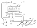
- the cylinder block 11 of the diesel engine 10 is formed with six cylinders 11a arranged in a row.
- the six cylinders 11a are connected to an intake manifold 12 for supplying intake air to each cylinder 11a and an exhaust manifold 16 into which exhaust from each cylinder 11a flows.
- the intake manifold 12 is provided with an intake pipe 13 as a passage for intake air.
- An air cleaner 14 is attached to the upstream end of the intake pipe 13, and a compressor 15 of the turbocharger TC is attached to the middle of the intake pipe 13.
- An exhaust pipe 18 and an EGR pipe 17 which are exhaust passages are connected to the exhaust manifold 16.
- the EGR pipe 17 connects the intake pipe 13 and the exhaust manifold 16 to cause the exhaust to flow into the intake pipe 13.
- a turbine 19 connected to the above-described compressor 15 is connected to an upstream portion of the exhaust pipe 18.
- An exhaust purification device 20 that purifies exhaust gas by removing particulates, for example, soot, in the exhaust pipe 18 is mounted on a downstream portion of the exhaust pipe 18.
- the exhaust gas purification device 20 is equipped with a filter 21 that collects particulates contained in the exhaust gas, and an upstream of the filter 21 is an exhaust gas purification treatment device burner for heating the exhaust gas supplied to the filter 21 (hereinafter referred to as “burner”). , Burner 30) is mounted.
- the filter 21 has a honeycomb structure formed of, for example, a porous ceramic, and captures particulates in the exhaust gas on the inner wall surfaces of a large number of columns constituting the honeycomb structure.
- the downstream portion of the compressor 15 in the intake pipe 13 and the burner 30 are connected by an air supply pipe 13a.
- An air valve 13b is attached in the middle of the air supply pipe 13a. When the air valve 13b is opened, intake air flows from the intake pipe 13 through the air supply pipe 13a into the exhaust purification device 20, and when the air valve 13b is closed, the intake pipe 13 connects to the exhaust purification device 20. The inflow of intake air is stopped.
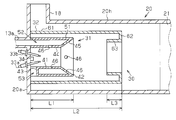
- An exhaust pipe 18 extending along the radial direction of the casing 20h is connected to an upstream end (base end) of the casing 20h formed in a cylindrical shape. Inside the housing 20h, a burner 30 and a filter 21 are accommodated in order from upstream to downstream.
- the burner 30 has a flame holder 31 formed in a cylindrical shape concentric with the housing 20h.
- the flame holder 31 is fixed to the upstream side wall 20a which is the base end wall of the housing 20h.
- a circulating portion 32 formed in a cylindrical shape concentric with the flame holder 31 is arranged with a gap between the flame holder 31 and the circulating portion 32. It is fixed to the upstream side wall 20a.
- two spark plugs 33 a and 33 b as ignition portions are fixed to the upstream side wall 20 a.
- one fuel injection nozzle 34 is fixed to the upstream side wall 20a inside the flame holder 31 and between the two spark plugs 33a and 33b.
- the flame stabilizer 31 is formed in a double cylinder shape including an inner cylinder part 41 and an outer cylinder part 51 extending from the upstream side wall 20a toward the filter 21, and a part of the base end thereof is the upstream side wall 20a. It is connected to.
- the inner cylinder part 41 is formed in a cylindrical shape concentric with the housing 20 h, and an ejection port 42 is formed at the tip of the inner cylinder part 41. That is, the inner cylinder part 41 in the flame holder 31 forms an ejection port 42 by the tip edge thereof.
- the base end of the inner cylinder part 41 is separated from the upstream side wall 20a by a passage forming part 43 which is a part of the inner cylinder part 41 in the circumferential direction, and the upstream side wall 20a at the remaining part of the inner cylinder part 41 in the circumferential direction. It is connected to.
- the inner cylinder portion 41 includes a constant diameter portion 44 that is a portion closer to the base end and a diameter-expanded portion 45 that is a portion closer to the distal end.
- the air supply hole 46 is formed.
- the plurality of air supply holes 46 are formed, for example, at a predetermined interval in the circumferential direction of the constant diameter portion 44, and are formed at a predetermined interval in the circumferential direction of the enlarged diameter portion 45.
- the outer cylinder portion 51 is formed in a cylindrical shape concentric with the housing 20h, and surrounds the inner cylinder portion 41 with a gap (air passage 52) between the outer cylinder portion 51 and the inner cylinder portion 41. .
- the distal end of the outer cylinder part 51 is connected to the distal end of the inner cylinder part 41 over the entire circumferential direction of the outer cylinder part 51, whereby an air passage that is a gap between the outer cylinder part 51 and the inner cylinder part 41. 52 is blocked.
- the base end of the outer cylinder part 51 is a part of the outer cylinder part 51 in the circumferential direction, is connected to the passage forming part 43 of the inner cylinder part 41, and is fixed to the upstream side wall 20a with the remaining part of the outer cylinder part 51 in the circumferential direction. Has been.
- the air passage 52 which is a gap between the inner cylinder part 41 and the outer cylinder part 51, communicates with the air supply pipe 13a through the upstream side wall 20a. .
- the inner cylinder part 41 and the outer cylinder part 51 are penetrated to radial direction, The inside of the inner cylinder part 41, the exterior of the outer cylinder part 51, and A communication passage 53 that communicates with each other is formed.
- the circulation portion 32 is formed in a cylindrical shape so as to extend from the upstream side wall 20 a toward the filter 21 and surround the entire flame holder 31, and at the tip located closer to the filter 21 with respect to the flame holder 31, the upstream side wall. It is folded back toward 20a.
- the circulating portion 32 has an outer guide portion 61 as a guide portion, and the outer guide portion 61 is formed in a cylindrical shape extending from the upstream side wall 20a toward the filter 21, and the outer guide portion 61, the flame stabilizer 31, and the like. A gap communicating with the communication path 53 is formed between the two.
- the length of the outer guide portion 61 in the central axis direction is set as the outer cylinder length L2, and the outer cylinder length L2 is set longer than the flame holder length L1.
- the circulating portion 32 also has an annular receiving portion 62 that faces the edge of the ejection port 42 in the central axis direction of the flame stabilizer 31.
- the flow receiving portion 62 extends inward in the radial direction of the outer guide portion 61 over the entire circumferential direction of the outer guide portion 61 at the tip of the outer guide portion 61.
- the circulating portion 32 further includes a cylindrical inner guide portion 63 that extends from the inner edge of the receiving portion 62 toward the ejection port 42.
- the length of the inner guide portion 63 in the central axis direction is set as the inner cylinder length L3, and the inner cylinder length L3 is set shorter than the length obtained by subtracting the flame holder length L1 from the outer cylinder length L2. ing.
- the fuel injection nozzle 34 is connected to, for example, a fuel pump for supplying fuel to the cylinder 11a.
- the fuel injection nozzle 34 injects fuel into a region surrounded by the flame holder 31 at a predetermined frequency and a predetermined pressure.
- the spark plugs 33a and 33b include an anode bar 33a and a cathode bar 33b.
- a voltage is applied between the anode bar 33a and the cathode bar 33b, a spark discharge is generated between the anode bar 33a and the cathode bar 33b.
- the fuel in the flame holder 31 is burned by igniting the mixture of fuel and air, so that the flame F is generated in the flame holder 31.
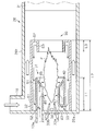
- FIG. 3 the flow of the exhaust gas supplied from the exhaust pipe 18 to the exhaust gas purification device 20 is indicated by a white arrow, the flow of the air supplied from the air supply pipe 13a is indicated by a two-dot chain line arrow, The flow of combustion gas generated by the combustion of fuel is indicated by solid arrows.
- the combustion gas referred to here includes the gas generated by the combustion of the fuel and the inside of the flame holder 31 heated by the flame F generated inside the flame holder 31 although it does not contribute to the combustion of the fuel. Gas.
- the circulation part 32 is heated by the flame F generated in the region surrounded by the flame holder 31 and the circulation part 32, the temperature of the exhaust gas in contact with the circulation part 32 is increased.
- the flame F is generated beyond the tip of the circulating portion 32, the exhaust passing between the tip of the circulating portion 32 and the filter 21 is heated by the flame F.
- the temperature of the filter 21 is raised to the extent that the soot accumulated on the filter 21 is oxidized.
- the fuel gas generated in the flame holder 31 is supplied to the filter 21 together with the heated exhaust gas, whereby the temperature of the filter 21 is increased.
- the outer guide part 61 surrounds the entire circumferential direction of the outer cylinder part 51, it is possible to increase the temperature of the flame holder 31 from around the flame holder 31. It becomes possible to guide most of the combustion gas flowing around to the inside of the inner cylinder portion 41. Moreover, since the enlarged diameter part 45 is formed in the inner cylinder part 41 of the flame holder 31, compared with the structure in which the enlarged diameter part 45 is not formed, the combustion gas as a fluid produced
- the air used for such combustion is supplied to the inside of the inner cylinder part 41 through the air passage 52 which is a gap between the inner cylinder part 41 and the outer cylinder part 51.
- the air flowing through the air passage 52 receives heat from the combustion gas flowing through the gap between the outer guide portion 61 and the outer cylinder portion 51. Accordingly, air having a higher temperature is supplied to the inside of the inner cylinder portion 41 than the configuration in which the air of the air supply pipe 13 a is directly supplied to the inside of the inner cylinder portion 41.
- the temperature inside the inner cylinder part 41 is raised, and this facilitates the combustion of fuel.
- the inner guide portion 63 of the circulating portion 32 is formed in a cylindrical shape extending from the inner edge of the receiving portion 62 toward the ejection port 42.
- Most of the combustion gas received by the receiving portion 62 flows in either the direction toward the inner edge of the receiving portion 62 or the direction toward the outer edge of the receiving portion 62.
- most of the fluid flowing toward the inner edge of the flow receiving portion 62 flows from the inner guide portion 63 toward the outer edge of the flow receiving portion 62 due to the collision with the inner guide portion 63, and as a result, the flow receiving portion.
- Most of the combustion gas received at 62 is guided to the communication path 53 by the outer guide portion 61. That is, most of the combustion gas received by the receiving portion 62 is biased toward the outer edge of the receiving portion 62, so that the fluid can be easily guided to the inside of the inner cylindrical portion 41.
- the communication path 53 is disposed at a portion closer to the proximal end with respect to the center in the central axis direction of the flame holder 31, particularly at the proximal end of the flame holder 31, the communication path 53 is located at a position closer to the distal end. Compared to the formed configuration, the flow path of the combustion gas inside the inner cylinder portion 41 becomes longer. Therefore, the temperature of the combustion region can be easily increased.
- the filter 21 when the filter 21 is regenerated immediately after the diesel engine 10 is started, the temperature of the exhaust gas supplied into the exhaust gas purification device 20 is not increased.
- the temperature in the combustion region is also low enough to prevent the ignition of fuel. In such a state, when the combustion gas is returned to the combustion region, the temperature of the combustion region is increased, so that the fuel is easily combusted.
- the combustion gas ejected from the ejection port 42 includes a combustion gas that diffuses around the ejection port 42 and a combustion gas that travels substantially straight from the ejection port 42.
- the combustion gas that diffuses around the ejection port 42 normally collides with the housing 20h that surrounds the ejection port 42 to increase the temperature of the housing 20h, and then ejects the combustion gas. Collides with direction exhaust and filter 21.
- the combustion gas that travels substantially straight from the ejection port 42 collides with the exhaust gas and the filter 21 without colliding with the housing 20h or the like. From the viewpoint of increasing the temperature increase rate of the filter 21, it is preferable that combustion gas that travels substantially straight from the outlet 42 is used for heating.
- the receiving portion 62 that faces the edge of the ejection port 42 in the central axis direction of the flame holder 31 directs the combustion gas that travels substantially straight from the ejection port 42 toward the filter 21. Lead. Therefore, a configuration in which a shielding portion such as the receiving portion 62 is disposed at a position facing the ejection port 42, in other words, compared to a configuration in which the receiving portion 62 is disposed radially inside the edge of the ejection port 42. It becomes possible to increase the rate of temperature rise in the filter 21.
- the annular flow receiving portion 62 guides the combustion gas that can diffuse from the outlet 42 and collide with the housing 20h to the outer guide portion 61 before the collision. Therefore, for example, the combustion gas guided to the combustion region is increased as compared with the configuration in which the receiving portion 62 is formed only in a part of the circumferential direction of the ejection port 42. As a result, it is possible to increase the temperature of the combustion region while suppressing the temperature increase rate of the filter 21 from being lowered.
- the flow receiving portion 62 facing the edge of the ejection port 42 in the central axis direction of the flame stabilizer 31 guides the combustion gas that travels substantially straight from the ejection port 42 to the filter 21, while the flow receiving portion 62
- the combustion gas diffusing from the ejection port 42 is received and guided to the outer guide portion 61. Accordingly, it is possible to increase the temperature inside the flame holder 31 while suppressing the temperature increase rate of the filter 21 from being lowered.
- the outer guide portion 61 surrounds the flame holder 31, the temperature of the flame holder 31 can be increased around the flame holder 31, and the fluid flowing around the flame holder 31 can be increased. It is also possible to introduce a large amount into the flame holder 31.
- FIGS. 4 to 6 show a cross-sectional structure taken along line 5-5 in FIG. 4, and FIG. 6 shows a cross-sectional structure taken along line 6-6 in FIG.
- the burner according to the second embodiment differs from the burner according to the first embodiment in the configuration related to the fuel supply in the burner and the configuration related to the air supply. Therefore, in the following, such differences will be described in detail, and other descriptions will be omitted.
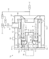
- the burner 70 includes a base body 70b formed in a disk shape, and a base end of a flame holder 31 formed in a cylindrical shape is fixed to the base body 70b.
- a circulating portion 32 is disposed outside the flame holder 31 with a gap between the flame holder 31 and a proximal end of the circulating portion 32 is fixed to the base body 70b.
- the flame holder 31 is formed in a double cylindrical shape including an inner cylinder part 41 and an outer cylinder part 51 extending from the base body 70 b toward the filter 21.
- the inner cylinder portion 41 of the flame stabilizer 31 is formed in a cylindrical shape concentric with the circulating portion 32, and an ejection port 42 is formed at the tip of the inner cylinder portion 41.
- the outer cylinder part 51 of the flame holder 31 is formed in a cylindrical shape concentric with the circulating part 32 and surrounds the inner cylinder part 41 with a gap between the outer cylinder part 51 and the inner cylinder part 41. .
- the tip of the inner cylinder part 41 and the tip of the outer cylinder part 51 are closed by a closing plate 54 formed in an annular shape.
- An air supply pipe 13 a is connected to an air passage 52 that is a gap between the inner cylinder portion 41 and the outer cylinder portion 51.
- a guide plate 55 formed in a plate shape facing the opening of the air supply pipe 13 a is fixed to the inner peripheral surface of the outer cylinder portion 51.
- a communication passage 53 that penetrates between the outer peripheral surface and the inner peripheral surface of the outer cylinder portion 51 is formed at the proximal end of the outer cylinder portion 51.
- the circulating portion 32 includes an outer guide portion 61, a flow receiving portion 62, and an inner guide portion 63, and is formed in a cylindrical shape surrounding the entire flame holder 31.
- the outer guide portion 61 is formed in a cylindrical shape extending from the base body 70b toward the filter 21.
- a receiving portion 62 formed in an annular shape facing the edge of the ejection port 42 is provided at the tip of the outer guide portion 61 at a portion closer to the filter 21 with respect to the flame holder 31.
- the flow receiving portion 62 extends inward in the radial direction over the entire circumferential direction of the outer guide portion 61, and is bent toward the proximal end of the outer guide portion 61 on the way inward in the radial direction.
- An inner guide portion 63 is provided on the inner edge of the flow receiving portion 62, and the inner guide portion 63 is formed in a cylindrical shape extending from the inner edge of the flow receiving portion 62 toward the base body 70b.
- an end portion (base end portion) close to the base body 70b is provided with a plurality of inner communication passages 71 for flowing air from the air supply pipe 13a into the inner cylinder portion 41. It is formed at intervals along the direction.
- the inner communication path 71 and the communication path 53 constitute a communication path.
- the inner cylinder part 41 is formed with a cut-and-raised piece 72 in which a part of the peripheral wall is cut and raised from the edge of each inner communication path 71 toward the inner side in the radial direction of the inner cylinder part 41.
- a plurality of air supply holes 46 penetrating the inner cylinder part 41 are formed in a portion of the inner cylinder part 41 close to the ejection port 42 with respect to the inner communication path 71.
- Each of the plurality of air supply holes 46 guides the air in the air passage 52 into the inner cylinder portion 41.
- a fuel supply part 35 for supplying fuel into the inner cylinder part 41 is fixed to the base body 70b.
- a fuel supply port is formed at the tip of the fuel supply unit 35, and the supply port is disposed in the inner cylinder portion 41.
- a fuel pump for supplying fuel to the engine is connected to the fuel supply unit 35, and the fuel supply unit 35 supplies the fuel supplied by the fuel pump into the inner cylinder portion 41 in a vaporized state.
- a connecting wall portion 73 is fixed between the inner communication path 71 and the air supply hole 46 in the inner peripheral surface of the inner cylinder portion 41.
- the connecting wall portion 73 is formed in an annular shape, and is bent toward the tip of the inner cylinder portion 41 while extending radially inward.
- the outer edge of the connecting wall 73 is connected to the inner cylinder 41 over the entire circumferential direction.
- a space surrounded by the inner cylinder portion 41 is partitioned into a first mixing chamber 81, a second mixing chamber 82, a third mixing chamber 83, a fourth mixing chamber 84, and a fifth mixing chamber 85.
- the space between the base body 70 b and the connecting wall portion 73 is a first mixing chamber 81, and air enters the first mixing chamber 81 from each inner communication passage 71, In addition, fuel enters from the fuel supply unit 35.
- the air swirling around the central axis of the flame holder 31 and the fuel injected toward the center of the air swirling are mixed.
- the base end portion of the mixing inner cylinder portion 74 formed in a cylindrical shape is connected to the distal end of the connection wall portion 73 in a state where the base end portion is passed through the connection wall portion 73. That is, of the two end portions of the mixed inner cylinder portion 74, the base end portion that is the end portion close to the base body 70 b is joined to the connection wall portion 73, and the connection wall portion 73 is connected to the inner peripheral surface of the inner cylinder portion 41. A gap between the mixing inner cylinder portion 74 is blocked. Of the two ends of the mixing inner cylinder 74, the tip, which is the end close to the ejection port 42, is open.
- An annular support plate 75 is fixed to a portion of the inner peripheral surface of the inner cylinder portion 41 that is close to the ejection port 42 with respect to the fixed portion of the connection wall portion 73.
- the mixing outer cylinder part 76 which is formed in a cylindrical shape and surrounds the mixing inner cylinder part 74 is connected. The distal end of the mixing outer cylinder part 76 is located closer to the ejection port 42 of the inner cylinder part 41 than the distal end of the mixing inner cylinder part 74, and a closing plate 77 that closes the opening is provided at the distal end of the mixing outer cylinder part 76. It is attached.
- the support plate 75 is formed with a plurality of air-fuel mixture supply ports 75a penetrating between the surface of the support plate 75 on the base 70b side and the surface on the ejection port 42 side.
- a wire net 78 that covers the plurality of air-fuel mixture supply ports 75 a is attached to the surface of the support plate 75 on the side of the ejection port 42.
- a second mixing chamber 82 which is a space surrounded by the inner peripheral surface of the mixing inner cylinder portion 74, is formed, and the second mixing chamber 82 exits from the first mixing chamber 81.
- the mixed gas enters.
- a third space which is surrounded by the inner peripheral surface of the mixing outer cylinder portion 76 and the closing plate 77 is located at a position closer to the ejection port 42 with respect to the second mixing chamber 82.
- a mixing chamber 83 is formed, and the air-fuel mixture that has come out of the second mixing chamber 82 enters the third mixing chamber 83.
- a fourth mixing chamber 84 is formed as a gap between the mixing inner cylinder portion 74 and the mixing outer cylinder portion 76, and the third mixing chamber 83 exits the fourth mixing chamber 84. Mixture enters.
- a fifth mixing chamber 85 is formed as a space surrounded by the inner peripheral surface of the inner cylinder portion 41, the support plate 75, and the connecting wall portion 73. Enters the mixed gas from the fourth mixing chamber 84.
- the first mixing chamber 81, the second mixing chamber 82, the third mixing chamber 83, the fourth mixing chamber 84, and the fifth mixing chamber 85 constitute one premixing chamber 80.
- a spark plug 33 is attached to the outer guide portion 61 of the circulating portion 32, and an ignition portion 33c formed at the tip of the spark plug 33 is near the tip of the flame holder 31 in the axial direction with respect to the support plate 75, and Further, it is disposed between the mixed outer cylinder portion 76 and the inner cylinder portion 41 in the radial direction.
- the clearance between the inner peripheral surface of the flame holder 31 and the outer peripheral surface of the mixed outer cylinder portion 76 and the space closer to the ejection port 42 than the closing plate 77 in the inner cylinder portion 41 are in the combustion region 90.
- the guide plate 55 is fixed to the inner peripheral surface of the outer cylinder portion 51, and is formed in a plate shape that covers a part of the opening of the air supply pipe 13a.
- the guide plate 55 is inclined inward in the radial direction from a fixed portion with respect to the inner peripheral surface, and thus has a slope closer to the outer peripheral surface of the inner cylinder portion 41 at a portion closer to the tip.
- the air flow from the air supply pipe 13 a into the outer cylinder portion 51 is changed from a flow inward in the radial direction to a flow along the outer peripheral surface of the inner cylinder portion 41 by colliding with the guide plate 55. Thereby, a swirl flow swirling around the inner cylinder part 41 is formed between the outer cylinder part 51 and the inner cylinder part 41.
- the plurality of cut and raised pieces 72 formed on the peripheral wall of the inner cylinder portion 41 are bent at an angle covering a part of the inner communication path 71.
- the cut-and-raised piece 72 forms a swirling flow in the inner cylinder portion 41 by guiding the air flowing from the inner communication passage 71 into the inner cylinder portion 41.
- the swirl flow formed by the guide plate 55 of the outer cylinder portion 51 and the swirl flow formed by the cut and raised piece 72 have the same swirling direction.
- the air from the inner communication path 71 and the fuel from the fuel supply unit 35 are mixed in the first mixing chamber 81. Then, an air-fuel mixture composed of air and fuel is generated.
- the air-fuel mixture generated in the first mixing chamber 81 sequentially passes from the second mixing chamber 82 to the fifth mixing chamber 85 and passes through the plurality of air-fuel supply ports 75a formed in the support plate 75 to the combustion region 90. enter.
- the fuel since the fuel previously mixed with air is supplied to the combustion region 90, the fuel is easily ignited as compared with the configuration in which air and fuel are separately supplied to the combustion region. Further, since the air heated in the air passage 52 is supplied to the premixing chamber 80, the temperature of the air-fuel mixture supplied to the combustion region 90 is increased as compared with a configuration in which the air is not heated. As a result, the air-fuel mixture is easily ignited.
- the air-fuel mixture is ignited by the spark plug 33, thereby generating a flame F extending toward the ejection port 42 of the flame holder 31.
- the air supplied to the combustion region 90 from the air supply hole 46 is mixed with the air-fuel mixture, it is possible to suppress the air-fuel mixture from becoming difficult to burn due to a lack of air.
- a part of the high-temperature fluid generated by the combustion of the air-fuel mixture is guided toward the receiving part 62 by the inner guide part 63, and the fluid guided to the receiving part 62 is the inner peripheral surface of the outer guide part 61.
- Flowing toward the base body 70b The fluid that reaches the vicinity of the base body 70 b flows from the communication passage 53 of the outer cylinder portion 51 into the air passage 52, and the fluid is mixed with air in the air passage 52. Since the high-temperature fluid mixed with air enters the first mixing chamber 81 from the inner communication path 71 of the inner cylinder portion 41, the mixture gas generated in the premixing chamber 80 is compared with a configuration in which no fluid flows. The temperature is increased.
- the effects listed below can be obtained.
- the fuel is premixed with air in the premixing chamber 80 before entering the combustion zone 90. Therefore, the air-fuel mixture is easily ignited as compared with the configuration in which the air-fuel mixture is not generated. Therefore, the fuel supplied to the combustion region 90 is easily burned.
- each said embodiment can also be suitably changed and implemented as follows.
- the receiving portion 62 may not be opposed to the edge of the ejection port 42 as long as it can receive the combustion gas ejected from the ejection port 42.
- the flow receiving portion 62 may be opposed to a region surrounded by the edge of the ejection port 42 in the central axis direction of the flame holder 31, that is, a region radially inward of the edge of the ejection port 42. Good.
- the flow receiving portion 62 may face the outer space in the radial direction with respect to the edge of the ejection port 42 in the central axis direction of the flame holder 31.
- the combustion gas ejected from the ejection port 42 is at least more radial than the edge of the ejection port 42. Combustion gas spreading outside is received by the receiving part. In this way, if the receiving part is configured to receive the combustion gas outside the ejection port 42, a part of the combustion gas ejected from the ejection port 42 is received by the receiving part, and then the outer guiding unit 61 receives the combustion gas. It is guided to the communication path 53 along.
- the flow receiving portion 62 may not be circular, and the outer edge of the flow receiving portion 62 may be, for example, a ring formed in a polygonal shape, or an elliptical ring. It may be.
- the receiving portion 62 may not be annular, and may be configured to correspond to only a part of the ejection port 42 in the circumferential direction. Even in such a configuration, the combustion gas is returned to the combustion region by receiving a considerable amount of the combustion gas by the receiving portion 62.
- the shape of the receiving portion 62 is appropriately designed to be a shape suitable for a position for receiving the combustion gas ejected from the ejection port 42, and is also suitably adapted to a shape suitable for returning the received combustion gas to the communication path. It only has to be designed.
- the outer side guide part 61 does not need to be cylindrical, for example, the cross section orthogonal to an axial direction may be square tube shape with a polygonal shape.
- the outer side guide part 61 does not need to be the cylinder shape which surrounds the flame holder 31, and is the structure formed so that it might correspond only to a part in the circumferential direction of the flame holder 31. Good.
- the structure which consists of a some board member formed at predetermined intervals in the circumferential direction of the flame holder 31 may be sufficient. Even in such a configuration, the combustion gas received by the flow receiving portion 62 is guided to the flame holder 31 along the outer guide portion 61.
- the inner side guide part 63 does not need to be cylindrical shape, and the cross section orthogonal to an axial direction may be polygonal square tube shape.
- the inner side guide part 63 does not need to be a cylinder shape, and the structure formed so that it might respond
- the inner guide portion 63 may be formed at a position closer to the outer edge of the flow receiving portion 62 with respect to the inner edge of the flow receiving portion 62. Even in such a configuration, compared with a configuration in which the inner guide portion is not formed, the combustion gas flows not only radially outward in the flow receiving portion 62, but therefore the combustion gas guide into the flame holder 31. Becomes easier.
- the circulating portion 32 may have a configuration in which the inner guide portion 63 is omitted. Even in such a configuration, the combustion gas that collides with the receiving portion 62 is returned to the combustion region, whereby the temperature of the combustion region is raised.
- the position of the communication path 53 is not limited to the position near the base end with respect to the center in the central axis direction of the flame holder 31, but from the center of the flame holder 31 in the central axis direction or from the center. May also be close to the tip. Even in such a configuration, the combustion gas flows into the combustion region not a little via the communication path, and therefore, the temperature in the combustion region is increased as compared with a configuration in which such combustion gas does not flow. Also in the second embodiment, the position of the communication path 53 does not have to be the end portion (base end portion) close to the base body 70 b in the outer cylinder portion 51, but may be formed in a portion closer to the ejection port 42.
- a plurality of passage forming portions 43 may be formed at the base end of the inner cylindrical portion 41 at intervals in the circumferential direction. According to such a configuration, the upstream side wall 20a and the inner cylindrical portion are formed. A plurality of communication passages 53 are formed by the portion 41. In the second embodiment, a plurality of communication passages 53 may be formed in the outer cylinder portion 51 at intervals in the circumferential direction.
- a plurality of communication passages 53 may be formed in the flame holder 31.
- a plurality of communication paths may be formed at a predetermined interval at the proximal end of the flame holder 31, and the proximal end of the flame holder 31 and a position closer to the distal end with respect to the proximal end
- a plurality of communication paths may be formed.
- the air passage 52 may not be formed in the flame holder 31. That is, the flame holder 31 may have a single cylindrical shape, and air may be directly supplied to the combustion region from the air supply pipe 13a. Even in such a configuration, the temperature in the combustion region is increased by the combustion gas returned to the flame holder 31 by the circulating portion 32, so that the fuel is easily combusted.
- the flame holder 31 may have a configuration in which the enlarged diameter portion 45 is omitted. Even in such a configuration, a part of the combustion gas ejected from the ejection port formed in the constant diameter portion 44 collides with the receiving portion 62. Therefore, a part of the fuel gas is returned to the combustion region by the circulating portion 32.
- the ignition source for burning the fuel is not limited to the ignition plugs 33a and 33b, but may be a glow plug, a laser ignition device, a plasma ignition device, or the like. Alternatively, it may be embodied as a combination of two or more of these. In short, any ignition unit capable of igniting an air-fuel mixture of fuel and air may be used.
- the housing 20h, the inner cylinder part 41, the outer cylinder part 51, and the circulation part 32 are not limited to a cylindrical shape, and are, for example, rectangular prisms having a polygonal cross section perpendicular to the axial direction.
- the inner cylinder portion 41 and the outer cylinder portion 51 may have a polygonal square tube cross section perpendicular to the axial direction.
- the air supply hole 46 formed in the inner cylinder portion 41 may be omitted, that is, air used for fuel combustion is supplied to the combustion region 90 only through the premixing chamber 80. It may be configured.
- the air supply pipe 13a may be connected to the base body 70b. That is, air used for fuel combustion may be put into the premixing chamber 80 without passing through the air passage 52 formed in the flame holder 31. In this case, the outer cylinder part 51 and the closing plate 54 of the flame holder 31 can be omitted.
- the position of the ejection port 42 of the flame holder 31 and the tip of the outer guide portion 61 may be further apart in the axial direction of the flame holder 31.
- the tip of the flame holder 31 may be expanded in diameter. According to such a configuration, it is possible to obtain an effect according to the above (7) which is an effect of the first embodiment.
- occlusion board 77 which are the division parts which divide the premixing chamber 80 and the combustion area
- a flat plate disposed inside the inner cylinder portion 41 and orthogonal to the axial direction of the inner cylinder portion 41 may be used.
- the connecting wall portion 73 and the mixing inner cylinder portion 74 may be omitted, and the partition portion may be configured by only the support plate 75, the mixing outer cylinder portion 76, and the closing plate 77.
- the partition section that partitions the premixing chamber 80 and the combustion region 90 partitions the space in which the air-fuel mixture is generated and the space in which the air-fuel mixture is ignited in the space partitioned by the inner cylinder portion 41. Any member may be used.
- the partition part comprised from the connection wall part 73, the mixing inner cylinder part 74, the support plate 75, the mixing outer cylinder part 76, and the obstruction
- the partition portion is preferably configured as described above.
- various catalysts used for purifying exhaust gas instead of the filter 21 may be provided on the downstream side of the burner 30.
- the filter 21 and the catalyst are connected in parallel to the downstream side of the burner 30, and combustion gas generated by combustion in the burner 30 or heated exhaust gas is supplied to both the filter 21 and the catalyst. But you can.
- the burners 30 and 70 are not limited to the front stage of the filter 21 in the exhaust pipe 18, and may be arranged in the rear stage of the filter 21 in the exhaust pipe 18.
- the fuel injection nozzle 34 may inject vaporized fuel.
- the fuel injected from the fuel injection nozzle 34 may be supplied from the common rail instead of from the fuel pump.
- a configuration in which a fuel pump for supplying fuel to the fuel injection nozzle 34 is separately mounted may be used.
- the fuel supply unit 35 may inject fuel that has not been vaporized.
- the air used for the combustion of fuel in the burners 30 and 70 may not be the air flowing through the intake pipe 13, but flows through a pipe connected to an air tank of the brake, for example. Air or air supplied from a blower for the burners 30 and 70 may be used.
- the engine on which the exhaust emission control device 20 is mounted is not limited to the diesel engine 10 but may be a gasoline engine.
Landscapes
- Engineering & Computer Science (AREA)
- Chemical & Material Sciences (AREA)
- Mechanical Engineering (AREA)
- General Engineering & Computer Science (AREA)
- Combustion & Propulsion (AREA)
- Environmental & Geological Engineering (AREA)
- Chemical Kinetics & Catalysis (AREA)
- Health & Medical Sciences (AREA)
- Toxicology (AREA)
- Processes For Solid Components From Exhaust (AREA)
- Filtering Of Dispersed Particles In Gases (AREA)
Abstract
Description
噴き出し口から噴き出される流体には、噴き出し口の周囲に拡散する流体と噴き出し口から略直進する流体とが含まれる。噴き出し口の周囲に拡散する流体は、通常、噴き出し口を囲む配管等に衝突して配管の温度を高めた後に、噴き出し方向の加熱対象物に到達する。一方で、噴き出し口から保炎器の中心軸に沿って略直進する流体は、配管等に衝突することなく、加熱対象に到達する。それゆえに、加熱対象物の昇温速度が高められる観点では、噴き出し口から略直進する流体がその加熱に用いられることが好ましい。
上記他の態様における案内部であれば、案内部が保炎器を囲むため、保炎器の周囲にて保炎器の温度を高めることが可能であり、また、保炎器の周囲に流れる流体の多くを保炎器の内部へ導くことが可能にもなる。
上記他の態様によれば、保炎器の先端寄りに連通路が形成される構成に比べて、保炎器の内部では、保炎器の内部に流れ込んだ流体の経路が長くなる。それゆえに、保炎器の内部の温度が高められやすくなり、ひいては、保炎器内にて燃料が燃焼されやすくなる。
上記他の態様によれば、噴き出し口からの流体が受流部によって受けられやすくなるため、環流部によって保炎器の内部に案内される流体がより多くなる。
バーナーの点火部には、燃料の燃焼に伴い、燃料そのものや燃料に含まれる成分が付着することがある。こうした付着物には炭素が含まれているため、点火部では、付着物によって必要とされる以外の部分においても絶縁性が低下する。これにより、点火部による燃料と空気との混合気に対する着火が不安定になる。この点で、上述の態様では、高温の流体が保炎器の内部に流れ込むことで点火部の温度が高められるため、点火部には、燃料や燃料の成分が付着しにくくなる。結果として、点火部による混合気に対する着火が不安定になりにくくなるため、燃料が燃焼されやすくなる。
上記他の態様によれば、燃料が予混合室で空気と予め混合されて燃焼領域に供給されるとともに、こうして供給された混合気が燃焼領域にて燃焼される。そのため、燃料と空気とが混合されない状態で燃焼領域にそれぞれ供給される構成と比べて、燃料が燃焼されやすくなる。
図1から図3を参照して、本開示におけるバーナーを具体化した第1実施形態を説明する。まず、バーナーが搭載されるディーゼルエンジンの全体構成について、図1を参照して説明する。なお、ここでは、ディーゼルエンジンに吸入される空気の通路、及び、ディーゼルエンジンから排出される排気の通路を中心に説明することとし、その他の構成については割愛する。以下では、「上流」及び「下流」は、ディーゼルエンジンにおける空気及び排気の流れ方向に関して規定される。
図1に示されるように、ディーゼルエンジン10のシリンダーブロック11には、一列に並んだ6つのシリンダー11aが形成されている。6つのシリンダー11aには、各シリンダー11aに吸入空気を供給するための吸気マニホールド12と、各シリンダー11aからの排気が流入する排気マニホールド16とが接続されている。
図2を参照して、バーナー30のより詳しい構成について、排気浄化装置20の構成の一部とともに説明する。
次に、上記バーナー30によるフィルター21の再生について図3を参照して説明する。なお、図3では、排気管18から排気浄化装置20に供給される排気の流れが白抜き矢印で示され、空気供給管13aから供給される空気の流れが二点鎖線の矢印で示され、燃料の燃焼によって生成される燃焼ガスの流れが実線矢印で示されている。ここでいう燃焼ガスには、燃料の燃焼によって生成されたガスと、燃料の燃焼には寄与していないものの、保炎器31の内部に生成された火炎Fによって加熱された保炎器31内の気体とが含まれる。
(1)保炎器31内での燃料の燃焼によって生成された燃焼ガスの一部は、受流部62に衝突して外側案内部61に案内されることで、保炎器31からフィルター21に向かう流れから、フィルター21から保炎器31に向かう流れに変えられる。そして、燃焼ガスが燃焼領域に流れ込むことで、燃焼領域の温度が高められる。結果として、保炎器31内では燃料が燃焼されやすくなる。
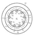
図4から図6を参照して本開示におけるバーナーの第2実施形態を説明する。なお、図5には、図4における5-5線に沿った断面構造が示され、図6には、図4における6-6線に沿った断面構造が示されている。第2実施形態のバーナーは、第1実施形態のバーナーと比べて、バーナーにおける燃料の供給に関わる構成、及び、空気の供給に関わる構成が異なる。そのため、以下では、こうした相違点を詳しく説明し、その他の説明を省略する。
図4に示されるように、バーナー70は、円板状に形成された基体70bを備え、基体70bには、円筒状に形成された保炎器31の基端が固定されている。保炎器31の外側には、保炎器31との間に隙間がある状態で環流部32が配置されるとともに、該環流部32の基端は、基体70bに固定されている。
内筒部41に囲まれる空間のうち基体70bと連結壁部73とに挟まれる空間は、第1混合室81であり、第1混合室81には、空気が各内側連通路71から入り、且つ、燃料が燃料供給部35から入る。第1混合室81では、保炎器31の中心軸を中心として旋回する空気と、空気の旋回する中心に向けて噴射される燃料とが混ざり合う。連結壁部73の先端には、円筒状に形成された混合内筒部74の基端部が、連結壁部73内に通された状態で連結されている。すなわち、混合内筒部74の2つの端部のうち基体70bに近い端部である基端部は、連結壁部73に接合され、連結壁部73は、内筒部41の内周面と混合内筒部74との間の隙間を塞いでいる。混合内筒部74の2つの端部のうち噴き出し口42に近い端部である先端部は開放されている。
バーナー70にて燃料が燃焼されるときには、まず、空気バルブ13bが開かれることによって、吸気管13内を流れる空気が、空気供給管13aから空気通路52に供給される。空気は、内筒部41の外周面に沿いながら、内筒部41の先端から基端に向けて流れ、内側連通路71から第1混合室81に入る。これにより、空気通路52を流れる空気が加熱される。
(9)燃料は、燃焼領域90に入る前に、予混合室80で空気と予め混合される。そのため、混合気が生成されない構成と比べて、混合気が着火されやすくなる。したがって、燃焼領域90に供給された燃料が燃焼されやすくなる。
第1実施形態及び第2実施形態において、受流部62は、噴き出し口42から噴き出される燃焼ガスを受けることのできる構成であれば、噴き出し口42の縁に対向していなくてもよい。詳しくは、受流部62は、保炎器31の中心軸方向において、噴き出し口42の縁に囲まれた領域、すなわち、噴き出し口42の縁よりも径方向の内側の領域と対向してもよい。あるいは、受流部62は、保炎器31の中心軸方向において、噴き出し口42の縁よりも径方向の外側の空間と対向してもよい。受流部62が、噴き出し口42の縁よりも径方向の外側に配置された構成であっても、噴き出し口42から噴き出された燃焼ガスのうち、少なくとも噴き出し口42の縁よりも径方向の外側に拡がった燃焼ガスが、受流部によって受けられる。このように、受流部が噴き出し口42の外側で燃焼ガスを受ける構成であれば噴き出し口42から噴き出された燃焼ガスの一部が受流部によって受けられた後、外側案内部61に沿って連通路53に案内される。
第1実施形態及び第2実施形態において、外側案内部61は保炎器31を囲む筒状でなくともよく、保炎器31の周方向における一部にのみ対応するように形成された構成でもよい。例えば、保炎器31の周方向において所定の間隔をあけて形成された複数の板部材からなる構成でもよい。こうした構成であっても、受流部62によって受けられた燃焼ガスは少なからず外側案内部61に沿って保炎器31に案内される。
第1実施形態及び第2実施形態において、内側案内部63は筒状でなくともよく、受流部62の周方向の一部にのみ対応するように形成された構成でもよい。こうした構成であっても、内側案内部が形成されていない構成と比べて、内側案内部が形成された部位では、燃焼ガスが受流部62の外縁寄りに偏るため、保炎器31内への燃焼ガスの案内が容易になる。
第1実施形態及び第2実施形態において、燃料を燃焼するための着火源は、点火プラグ33a,33bに限らず、グロープラグ、レーザー点火装置、及び、プラズマ点火装置等であってもよく、あるいは、これらの2つ以上の組合せとして具体化されてもよい。要は、燃料と空気との混合気に着火が可能な点火部であればよい。
第2実施形態においても、第1実施形態と同様、保炎器31の先端が拡径されていてもよい。こうした構成によれば、第1実施形態の効果である上記(7)に準じた効果を得ることができる。
第1実施形態において、燃料噴射ノズル34から噴射される燃料が、燃料ポンプからではなく、コモンレールから供給される構成であってもよい。あるいは、燃料噴射ノズル34に燃料を供給するための燃料ポンプが別途搭載された構成でもよい。
第1実施形態及び第2実施形態において、バーナー30,70での燃料の燃焼に用いられる空気が、吸気管13を流れる空気でなくともよく、例えば、ブレーキの空気タンクに接続された配管を流れる空気や、バーナー30,70用のブロワから供給される空気であってもよい。
Claims (9)
- エンジンの排気管で排気を浄化する排気浄化装置に用いられるバーナーであって、
燃焼によって生成される流体が噴き出される噴き出し口をその先端に有する筒状の保炎器と、
前記保炎器の内部と前記保炎器の外部とを連通する連通路と、
前記保炎器の外側に配置された環流部とを備え、
前記環流部は、
前記噴き出し口から噴き出される前記流体を受ける受流部と、
前記受流部の受ける流体を前記受流部から前記連通路へ案内する案内部とを備える
バーナー。 - 前記受流部は、
前記保炎器の中心軸方向において前記噴き出し口の縁と対向するように環状に形成されている
請求項1に記載のバーナー。 - 前記案内部は、
前記保炎器を囲むように形成されている
請求項2に記載のバーナー。 - 前記案内部は、
前記保炎器を囲む筒状の外側案内部と、
前記受流部の内縁から前記噴き出し口に向けて延びる筒状の内側案内部とを備える
請求項2または3に記載のバーナー。 - 前記連通路は、
前記保炎器における中心軸方向の中央に対して、前記保炎器の基端寄りに配置されている
請求項1から4のいずれか一項に記載のバーナー。 - 前記保炎器は、内筒部と該内筒部を囲む外筒部とを含み、
前記保炎器には、
前記内筒部と前記外筒部との間の隙間に空気を供給する空気供給管が接続され、
前記内筒部には、
前記内筒部と前記外筒部との間の隙間を前記内筒部の内部に連通させる空気供給孔が形成されている
請求項1から5のいずれか一項に記載のバーナー。 - 前記保炎器の先端は、拡径されている
請求項1から6のいずれか一項に記載のバーナー。 - 前記保炎器の内部に、点火部をさらに備える
請求項1から7のいずれか一項に記載のバーナー。 - 前記保炎器の内部は、
燃料と空気とから構成される混合気を生成する予混合室と、
前記予混合室から供給された前記混合気が燃焼される燃焼領域とに区画される
請求項1から8のいずれか一項に記載のバーナー。
Priority Applications (4)
| Application Number | Priority Date | Filing Date | Title |
|---|---|---|---|
| CN201380001011.5A CN103562507B (zh) | 2012-05-25 | 2013-05-22 | 排气净化装置用燃烧器 |
| JP2013539065A JP5555382B2 (ja) | 2012-05-25 | 2013-05-22 | 排気浄化装置用バーナー |
| US14/127,569 US20140123632A1 (en) | 2012-05-25 | 2013-05-22 | Burner for exhaust purifying device |
| EP13794160.5A EP2713022B1 (en) | 2012-05-25 | 2013-05-22 | Burner for exhaust gas purification device |
Applications Claiming Priority (2)
| Application Number | Priority Date | Filing Date | Title |
|---|---|---|---|
| JP2012119897 | 2012-05-25 | ||
| JP2012-119897 | 2012-05-25 |
Publications (1)
| Publication Number | Publication Date |
|---|---|
| WO2013176184A1 true WO2013176184A1 (ja) | 2013-11-28 |
Family
ID=49623869
Family Applications (1)
| Application Number | Title | Priority Date | Filing Date |
|---|---|---|---|
| PCT/JP2013/064240 Ceased WO2013176184A1 (ja) | 2012-05-25 | 2013-05-22 | 排気浄化装置用バーナー |
Country Status (5)
| Country | Link |
|---|---|
| US (1) | US20140123632A1 (ja) |
| EP (1) | EP2713022B1 (ja) |
| JP (1) | JP5555382B2 (ja) |
| CN (1) | CN103562507B (ja) |
| WO (1) | WO2013176184A1 (ja) |
Cited By (3)
| Publication number | Priority date | Publication date | Assignee | Title |
|---|---|---|---|---|
| WO2015128957A1 (ja) * | 2014-02-26 | 2015-09-03 | 東芝燃料電池システム株式会社 | バーナー |
| JP2019207049A (ja) * | 2018-05-28 | 2019-12-05 | 三菱重工業株式会社 | 燃料噴射装置及びガスタービン |
| JP2022117437A (ja) * | 2021-01-29 | 2022-08-10 | マレリ・ヨーロッパ・エッセ・ピ・ア | 内燃機関の排気システムのための加熱装置 |
Families Citing this family (26)
| Publication number | Priority date | Publication date | Assignee | Title |
|---|---|---|---|---|
| EP2295858A1 (de) * | 2009-08-03 | 2011-03-16 | Siemens Aktiengesellschaft | Stabilisierung der Flamme eines Brenners |
| US9674214B2 (en) | 2013-03-15 | 2017-06-06 | Zerofox, Inc. | Social network profile data removal |
| US9027134B2 (en) | 2013-03-15 | 2015-05-05 | Zerofox, Inc. | Social threat scoring |
| US9055097B1 (en) | 2013-03-15 | 2015-06-09 | Zerofox, Inc. | Social network scanning |
| US9674212B2 (en) | 2013-03-15 | 2017-06-06 | Zerofox, Inc. | Social network data removal |
| US9191411B2 (en) | 2013-03-15 | 2015-11-17 | Zerofox, Inc. | Protecting against suspect social entities |
| CN104879217A (zh) * | 2014-02-27 | 2015-09-02 | 洪瑞桐 | 辐射热能柴油触媒清洁系统 |
| US9544325B2 (en) | 2014-12-11 | 2017-01-10 | Zerofox, Inc. | Social network security monitoring |
| US10516567B2 (en) | 2015-07-10 | 2019-12-24 | Zerofox, Inc. | Identification of vulnerability to social phishing |
| KR101740576B1 (ko) * | 2016-06-20 | 2017-05-26 | (주)대신전기산업 | 가스버너 |
| US11256812B2 (en) | 2017-01-31 | 2022-02-22 | Zerofox, Inc. | End user social network protection portal |
| US11394722B2 (en) | 2017-04-04 | 2022-07-19 | Zerofox, Inc. | Social media rule engine |
| US10868824B2 (en) | 2017-07-31 | 2020-12-15 | Zerofox, Inc. | Organizational social threat reporting |
| US11165801B2 (en) | 2017-08-15 | 2021-11-02 | Zerofox, Inc. | Social threat correlation |
| US11418527B2 (en) | 2017-08-22 | 2022-08-16 | ZeroFOX, Inc | Malicious social media account identification |
| US11403400B2 (en) | 2017-08-31 | 2022-08-02 | Zerofox, Inc. | Troll account detection |
| US11134097B2 (en) | 2017-10-23 | 2021-09-28 | Zerofox, Inc. | Automated social account removal |
| IT202000022396A1 (it) * | 2020-09-23 | 2022-03-23 | Marelli Europe Spa | Dispositivo riscaldatore per un sistema di scarico di un motore a combustione interna |
| KR102383947B1 (ko) * | 2020-11-19 | 2022-04-07 | 주식회사 정안 | 연소실 교체형 디젤 배기가스 연소용 버너 |
| KR102383946B1 (ko) * | 2020-11-19 | 2022-04-07 | 주식회사 정안 | 디젤 배기가스 연소용 버너 |
| US11674427B2 (en) | 2020-12-23 | 2023-06-13 | Marelli Europe S.P.A. | Heating device for an exhaust system of an internal combustion engine |
| DE102021001580A1 (de) * | 2021-03-25 | 2022-09-29 | Mercedes-Benz Group AG | Brenner für ein Kraftfahrzeug sowie Kraftfahrzeug mit wenigstens einem solchen Brenner |
| DE102021113761A1 (de) | 2021-05-27 | 2022-12-01 | Hug Engineering Ag | Abgaserwärmungsvorrichtung für Verbrennungsmotoren, insbesondere für Schiffsmotoren |
| CN113339799B (zh) * | 2021-07-08 | 2023-05-12 | 华帝股份有限公司 | 用于圣火盆的可调节式稳焰装置 |
| KR102472623B1 (ko) * | 2022-03-23 | 2022-11-29 | 주식회사 에코플랜텍 | 하이브리드 버너 |
| KR102771743B1 (ko) * | 2024-08-02 | 2025-02-24 | (주)창화에너지 | 버너 입구 스팀 분사형 연소 시스템 |
Citations (4)
| Publication number | Priority date | Publication date | Assignee | Title |
|---|---|---|---|---|
| JP2009030608A (ja) * | 2007-07-30 | 2009-02-12 | Korea Inst Of Machinery & Materials | プラズマバーナ及び煤煙濾過装置 |
| JP4393858B2 (ja) * | 2003-12-22 | 2010-01-06 | ボッシュ株式会社 | 排気後処理装置用補助装置 |
| US20110064369A1 (en) * | 2009-09-15 | 2011-03-17 | Kabushiki Kaisha Toshiba | Flexible wiring board, manufacturing method thereof and flexible wiring device |
| JP2011157824A (ja) | 2010-01-29 | 2011-08-18 | Hino Motors Ltd | 排気浄化装置 |
Family Cites Families (19)
| Publication number | Priority date | Publication date | Assignee | Title |
|---|---|---|---|---|
| US2918117A (en) * | 1956-10-04 | 1959-12-22 | Petro Chem Process Company Inc | Heavy fuel burner with combustion gas recirculating means |
| US3319692A (en) * | 1965-06-01 | 1967-05-16 | Iit Res Inst | Oil burner |
| BE795261A (fr) * | 1972-02-10 | 1973-05-29 | Bailey Frank W | Bruleurs canon a retention de flamme bleue et systemes d'echangeur de chaleur |
| JPS5752484B2 (ja) * | 1973-07-16 | 1982-11-08 | ||
| JPS5069635A (ja) * | 1973-10-23 | 1975-06-10 | ||
| JPS5069634A (ja) * | 1973-10-23 | 1975-06-10 | ||
| JPS5274928A (en) * | 1975-12-19 | 1977-06-23 | Hitachi Zosen Corp | Liquid fuel gasification-combustion method |
| US4130388A (en) * | 1976-09-15 | 1978-12-19 | Flynn Burner Corporation | Non-contaminating fuel burner |
| JPS5993913A (ja) * | 1982-11-19 | 1984-05-30 | Nissan Motor Co Ltd | 内燃機関の排気微粒子処理装置 |
| JPS61280305A (ja) * | 1985-06-04 | 1986-12-10 | Isuzu Motors Ltd | 燃焼器の構造 |
| EP0599395A1 (en) * | 1992-11-20 | 1994-06-01 | WITTEVEEN, Gustaaf Jan | Low NOx combustor |
| NL9301581A (nl) * | 1993-09-13 | 1995-04-03 | Gastec Nv | Compacte gasgestookte infraroodstraler in gesloten uitvoering. |
| JPH07318010A (ja) * | 1994-05-23 | 1995-12-08 | Miura Kenkyusho:Kk | 気化燃焼バーナ |
| FR2829071B1 (fr) * | 2001-09-04 | 2005-08-05 | Renault | Module de commandes sous le volant |
| JP4614448B2 (ja) * | 2005-11-25 | 2011-01-19 | ボッシュ株式会社 | 内燃機関の排気浄化装置 |
| KR100866327B1 (ko) * | 2007-07-30 | 2008-10-31 | 한국기계연구원 | 플라즈마 버너 및 매연여과장치 |
| US20090178394A1 (en) * | 2008-01-15 | 2009-07-16 | Crane Jr Samuel N | Method and Apparatus for Cleaning Electrodes of a Fuel-Fired Burner of an Emission Abatement Assembly |
| US8869518B2 (en) * | 2009-09-15 | 2014-10-28 | Tenneco Automotive Operating Company Inc. | Burner for a diesel aftertreatment system |
| JP5566134B2 (ja) * | 2010-03-05 | 2014-08-06 | 日野自動車株式会社 | 排気ガス昇温用燃焼器 |
-
2013
- 2013-05-22 EP EP13794160.5A patent/EP2713022B1/en not_active Not-in-force
- 2013-05-22 US US14/127,569 patent/US20140123632A1/en not_active Abandoned
- 2013-05-22 WO PCT/JP2013/064240 patent/WO2013176184A1/ja not_active Ceased
- 2013-05-22 CN CN201380001011.5A patent/CN103562507B/zh not_active Expired - Fee Related
- 2013-05-22 JP JP2013539065A patent/JP5555382B2/ja not_active Expired - Fee Related
Patent Citations (4)
| Publication number | Priority date | Publication date | Assignee | Title |
|---|---|---|---|---|
| JP4393858B2 (ja) * | 2003-12-22 | 2010-01-06 | ボッシュ株式会社 | 排気後処理装置用補助装置 |
| JP2009030608A (ja) * | 2007-07-30 | 2009-02-12 | Korea Inst Of Machinery & Materials | プラズマバーナ及び煤煙濾過装置 |
| US20110064369A1 (en) * | 2009-09-15 | 2011-03-17 | Kabushiki Kaisha Toshiba | Flexible wiring board, manufacturing method thereof and flexible wiring device |
| JP2011157824A (ja) | 2010-01-29 | 2011-08-18 | Hino Motors Ltd | 排気浄化装置 |
Non-Patent Citations (1)
| Title |
|---|
| See also references of EP2713022A4 |
Cited By (6)
| Publication number | Priority date | Publication date | Assignee | Title |
|---|---|---|---|---|
| WO2015128957A1 (ja) * | 2014-02-26 | 2015-09-03 | 東芝燃料電池システム株式会社 | バーナー |
| JPWO2015128957A1 (ja) * | 2014-02-26 | 2017-03-30 | 東芝燃料電池システム株式会社 | バーナー |
| DE112014006414B4 (de) * | 2014-02-26 | 2020-06-04 | Futaba Industrial Co., Ltd. | Brenner |
| JP2019207049A (ja) * | 2018-05-28 | 2019-12-05 | 三菱重工業株式会社 | 燃料噴射装置及びガスタービン |
| JP6995696B2 (ja) | 2018-05-28 | 2022-01-17 | 三菱重工業株式会社 | 燃料噴射装置及びガスタービン |
| JP2022117437A (ja) * | 2021-01-29 | 2022-08-10 | マレリ・ヨーロッパ・エッセ・ピ・ア | 内燃機関の排気システムのための加熱装置 |
Also Published As
| Publication number | Publication date |
|---|---|
| EP2713022A1 (en) | 2014-04-02 |
| EP2713022A4 (en) | 2014-10-15 |
| US20140123632A1 (en) | 2014-05-08 |
| EP2713022B1 (en) | 2015-11-18 |
| JPWO2013176184A1 (ja) | 2016-01-14 |
| CN103562507B (zh) | 2014-09-17 |
| JP5555382B2 (ja) | 2014-07-23 |
| CN103562507A (zh) | 2014-02-05 |
Similar Documents
| Publication | Publication Date | Title |
|---|---|---|
| JP5555382B2 (ja) | 排気浄化装置用バーナー | |
| JP5740057B2 (ja) | バーナー | |
| JP5740056B2 (ja) | バーナー | |
| JP5566134B2 (ja) | 排気ガス昇温用燃焼器 | |
| JP6084605B2 (ja) | バーナー、および、フィルター再生装置 | |
| JP6050334B2 (ja) | 排気浄化装置用バーナー | |
| EP2400123A2 (en) | Plasma burner and diesel particulate filter trap | |
| JPS5993913A (ja) | 内燃機関の排気微粒子処理装置 | |
| JP5695273B2 (ja) | 排気浄化装置用バーナー | |
| CN101372910A (zh) | 等离子燃烧器和柴油机颗粒过滤器捕集器 | |
| KR101323610B1 (ko) | 배기가스 승온용 버너장치 | |
| JP2013245609A (ja) | 排気浄化装置用バーナー | |
| JP6123191B2 (ja) | 排気システム | |
| JP6385704B2 (ja) | バーナー | |
| JP6109583B2 (ja) | バーナー | |
| JP6151078B2 (ja) | バーナー | |
| JP2017211116A (ja) | バーナー | |
| JP2013024195A (ja) | 排気昇温装置および排気昇温方法 | |
| KR101036178B1 (ko) | 플라즈마 반응장치 |
Legal Events
| Date | Code | Title | Description |
|---|---|---|---|
| ENP | Entry into the national phase |
Ref document number: 2013539065 Country of ref document: JP Kind code of ref document: A |
|
| WWE | Wipo information: entry into national phase |
Ref document number: 2013794160 Country of ref document: EP |
|
| WWE | Wipo information: entry into national phase |
Ref document number: 14127569 Country of ref document: US |
|
| 121 | Ep: the epo has been informed by wipo that ep was designated in this application |
Ref document number: 13794160 Country of ref document: EP Kind code of ref document: A1 |
|
| NENP | Non-entry into the national phase |
Ref country code: DE |