WO2013179435A1 - 排気管の耐久性向上方法及び排気浄化装置 - Google Patents
排気管の耐久性向上方法及び排気浄化装置 Download PDFInfo
- Publication number
- WO2013179435A1 WO2013179435A1 PCT/JP2012/064051 JP2012064051W WO2013179435A1 WO 2013179435 A1 WO2013179435 A1 WO 2013179435A1 JP 2012064051 W JP2012064051 W JP 2012064051W WO 2013179435 A1 WO2013179435 A1 WO 2013179435A1
- Authority
- WO
- WIPO (PCT)
- Prior art keywords
- exhaust
- exhaust pipe
- welded portion
- durability
- pipe
- Prior art date
- Legal status (The legal status is an assumption and is not a legal conclusion. Google has not performed a legal analysis and makes no representation as to the accuracy of the status listed.)
- Ceased
Links
Images



Classifications
-
- C—CHEMISTRY; METALLURGY
- C21—METALLURGY OF IRON
- C21D—MODIFYING THE PHYSICAL STRUCTURE OF FERROUS METALS; GENERAL DEVICES FOR HEAT TREATMENT OF FERROUS OR NON-FERROUS METALS OR ALLOYS; MAKING METAL MALLEABLE, e.g. BY DECARBURISATION OR TEMPERING
- C21D7/00—Modifying the physical properties of iron or steel by deformation
- C21D7/02—Modifying the physical properties of iron or steel by deformation by cold working
- C21D7/04—Modifying the physical properties of iron or steel by deformation by cold working of the surface
- C21D7/06—Modifying the physical properties of iron or steel by deformation by cold working of the surface by shot-peening or the like
-
- B—PERFORMING OPERATIONS; TRANSPORTING
- B21—MECHANICAL METAL-WORKING WITHOUT ESSENTIALLY REMOVING MATERIAL; PUNCHING METAL
- B21D—WORKING OR PROCESSING OF SHEET METAL OR METAL TUBES, RODS OR PROFILES WITHOUT ESSENTIALLY REMOVING MATERIAL; PUNCHING METAL
- B21D31/00—Other methods for working sheet metal, metal tubes, metal profiles
- B21D31/06—Deforming sheet metal, tubes or profiles by sequential impacts, e.g. hammering, beating, peen forming
-
- B—PERFORMING OPERATIONS; TRANSPORTING
- B24—GRINDING; POLISHING
- B24C—ABRASIVE OR RELATED BLASTING WITH PARTICULATE MATERIAL
- B24C1/00—Methods for use of abrasive blasting for producing particular effects; Use of auxiliary equipment in connection with such methods
- B24C1/10—Methods for use of abrasive blasting for producing particular effects; Use of auxiliary equipment in connection with such methods for compacting surfaces, e.g. shot-peening
-
- B—PERFORMING OPERATIONS; TRANSPORTING
- B24—GRINDING; POLISHING
- B24C—ABRASIVE OR RELATED BLASTING WITH PARTICULATE MATERIAL
- B24C3/00—Abrasive blasting machines or devices; Plants
- B24C3/32—Abrasive blasting machines or devices; Plants designed for abrasive blasting of particular work, e.g. the internal surfaces of cylinder blocks
- B24C3/325—Abrasive blasting machines or devices; Plants designed for abrasive blasting of particular work, e.g. the internal surfaces of cylinder blocks for internal surfaces, e.g. of tubes
-
- C—CHEMISTRY; METALLURGY
- C21—METALLURGY OF IRON
- C21D—MODIFYING THE PHYSICAL STRUCTURE OF FERROUS METALS; GENERAL DEVICES FOR HEAT TREATMENT OF FERROUS OR NON-FERROUS METALS OR ALLOYS; MAKING METAL MALLEABLE, e.g. BY DECARBURISATION OR TEMPERING
- C21D9/00—Heat treatment, e.g. annealing, hardening, quenching or tempering, adapted for particular articles; Furnaces therefor
- C21D9/50—Heat treatment, e.g. annealing, hardening, quenching or tempering, adapted for particular articles; Furnaces therefor for welded joints
-
- F—MECHANICAL ENGINEERING; LIGHTING; HEATING; WEAPONS; BLASTING
- F01—MACHINES OR ENGINES IN GENERAL; ENGINE PLANTS IN GENERAL; STEAM ENGINES
- F01N—GAS-FLOW SILENCERS OR EXHAUST APPARATUS FOR MACHINES OR ENGINES IN GENERAL; GAS-FLOW SILENCERS OR EXHAUST APPARATUS FOR INTERNAL-COMBUSTION ENGINES
- F01N13/00—Exhaust or silencing apparatus characterised by constructional features
- F01N13/009—Exhaust or silencing apparatus characterised by constructional features having two or more separate purifying devices arranged in series
- F01N13/0097—Exhaust or silencing apparatus characterised by constructional features having two or more separate purifying devices arranged in series the purifying devices are arranged in a single housing
-
- F—MECHANICAL ENGINEERING; LIGHTING; HEATING; WEAPONS; BLASTING
- F01—MACHINES OR ENGINES IN GENERAL; ENGINE PLANTS IN GENERAL; STEAM ENGINES
- F01N—GAS-FLOW SILENCERS OR EXHAUST APPARATUS FOR MACHINES OR ENGINES IN GENERAL; GAS-FLOW SILENCERS OR EXHAUST APPARATUS FOR INTERNAL-COMBUSTION ENGINES
- F01N13/00—Exhaust or silencing apparatus characterised by constructional features
- F01N13/16—Selection of particular materials
-
- F—MECHANICAL ENGINEERING; LIGHTING; HEATING; WEAPONS; BLASTING
- F01—MACHINES OR ENGINES IN GENERAL; ENGINE PLANTS IN GENERAL; STEAM ENGINES
- F01N—GAS-FLOW SILENCERS OR EXHAUST APPARATUS FOR MACHINES OR ENGINES IN GENERAL; GAS-FLOW SILENCERS OR EXHAUST APPARATUS FOR INTERNAL-COMBUSTION ENGINES
- F01N13/00—Exhaust or silencing apparatus characterised by constructional features
- F01N13/18—Construction facilitating manufacture, assembly, or disassembly
-
- F—MECHANICAL ENGINEERING; LIGHTING; HEATING; WEAPONS; BLASTING
- F01—MACHINES OR ENGINES IN GENERAL; ENGINE PLANTS IN GENERAL; STEAM ENGINES
- F01N—GAS-FLOW SILENCERS OR EXHAUST APPARATUS FOR MACHINES OR ENGINES IN GENERAL; GAS-FLOW SILENCERS OR EXHAUST APPARATUS FOR INTERNAL-COMBUSTION ENGINES
- F01N3/00—Exhaust or silencing apparatus having means for purifying, rendering innocuous, or otherwise treating exhaust
- F01N3/02—Exhaust or silencing apparatus having means for purifying, rendering innocuous, or otherwise treating exhaust for cooling, or for removing solid constituents of, exhaust
-
- F—MECHANICAL ENGINEERING; LIGHTING; HEATING; WEAPONS; BLASTING
- F01—MACHINES OR ENGINES IN GENERAL; ENGINE PLANTS IN GENERAL; STEAM ENGINES
- F01N—GAS-FLOW SILENCERS OR EXHAUST APPARATUS FOR MACHINES OR ENGINES IN GENERAL; GAS-FLOW SILENCERS OR EXHAUST APPARATUS FOR INTERNAL-COMBUSTION ENGINES
- F01N3/00—Exhaust or silencing apparatus having means for purifying, rendering innocuous, or otherwise treating exhaust
- F01N3/08—Exhaust or silencing apparatus having means for purifying, rendering innocuous, or otherwise treating exhaust for rendering innocuous
- F01N3/10—Exhaust or silencing apparatus having means for purifying, rendering innocuous, or otherwise treating exhaust for rendering innocuous by thermal or catalytic conversion of noxious components of exhaust
- F01N3/18—Exhaust or silencing apparatus having means for purifying, rendering innocuous, or otherwise treating exhaust for rendering innocuous by thermal or catalytic conversion of noxious components of exhaust characterised by methods of operation; Control
- F01N3/20—Exhaust or silencing apparatus having means for purifying, rendering innocuous, or otherwise treating exhaust for rendering innocuous by thermal or catalytic conversion of noxious components of exhaust characterised by methods of operation; Control specially adapted for catalytic conversion
- F01N3/206—Adding periodically or continuously substances to exhaust gases for promoting purification, e.g. catalytic material in liquid form, NOx reducing agents
- F01N3/2066—Selective catalytic reduction [SCR]
-
- F—MECHANICAL ENGINEERING; LIGHTING; HEATING; WEAPONS; BLASTING
- F01—MACHINES OR ENGINES IN GENERAL; ENGINE PLANTS IN GENERAL; STEAM ENGINES
- F01N—GAS-FLOW SILENCERS OR EXHAUST APPARATUS FOR MACHINES OR ENGINES IN GENERAL; GAS-FLOW SILENCERS OR EXHAUST APPARATUS FOR INTERNAL-COMBUSTION ENGINES
- F01N3/00—Exhaust or silencing apparatus having means for purifying, rendering innocuous, or otherwise treating exhaust
- F01N3/08—Exhaust or silencing apparatus having means for purifying, rendering innocuous, or otherwise treating exhaust for rendering innocuous
- F01N3/10—Exhaust or silencing apparatus having means for purifying, rendering innocuous, or otherwise treating exhaust for rendering innocuous by thermal or catalytic conversion of noxious components of exhaust
- F01N3/18—Exhaust or silencing apparatus having means for purifying, rendering innocuous, or otherwise treating exhaust for rendering innocuous by thermal or catalytic conversion of noxious components of exhaust characterised by methods of operation; Control
- F01N3/20—Exhaust or silencing apparatus having means for purifying, rendering innocuous, or otherwise treating exhaust for rendering innocuous by thermal or catalytic conversion of noxious components of exhaust characterised by methods of operation; Control specially adapted for catalytic conversion
- F01N3/206—Adding periodically or continuously substances to exhaust gases for promoting purification, e.g. catalytic material in liquid form, NOx reducing agents
- F01N3/208—Control of selective catalytic reduction [SCR], e.g. by adjusting the dosing of reducing agent
-
- F—MECHANICAL ENGINEERING; LIGHTING; HEATING; WEAPONS; BLASTING
- F01—MACHINES OR ENGINES IN GENERAL; ENGINE PLANTS IN GENERAL; STEAM ENGINES
- F01N—GAS-FLOW SILENCERS OR EXHAUST APPARATUS FOR MACHINES OR ENGINES IN GENERAL; GAS-FLOW SILENCERS OR EXHAUST APPARATUS FOR INTERNAL-COMBUSTION ENGINES
- F01N3/00—Exhaust or silencing apparatus having means for purifying, rendering innocuous, or otherwise treating exhaust
- F01N3/08—Exhaust or silencing apparatus having means for purifying, rendering innocuous, or otherwise treating exhaust for rendering innocuous
- F01N3/10—Exhaust or silencing apparatus having means for purifying, rendering innocuous, or otherwise treating exhaust for rendering innocuous by thermal or catalytic conversion of noxious components of exhaust
- F01N3/24—Exhaust or silencing apparatus having means for purifying, rendering innocuous, or otherwise treating exhaust for rendering innocuous by thermal or catalytic conversion of noxious components of exhaust characterised by constructional aspects of converting apparatus
- F01N3/28—Construction of catalytic reactors
- F01N3/2892—Exhaust flow directors or the like, e.g. upstream of catalytic device
-
- C—CHEMISTRY; METALLURGY
- C21—METALLURGY OF IRON
- C21D—MODIFYING THE PHYSICAL STRUCTURE OF FERROUS METALS; GENERAL DEVICES FOR HEAT TREATMENT OF FERROUS OR NON-FERROUS METALS OR ALLOYS; MAKING METAL MALLEABLE, e.g. BY DECARBURISATION OR TEMPERING
- C21D2211/00—Microstructure comprising significant phases
- C21D2211/005—Ferrite
-
- F—MECHANICAL ENGINEERING; LIGHTING; HEATING; WEAPONS; BLASTING
- F01—MACHINES OR ENGINES IN GENERAL; ENGINE PLANTS IN GENERAL; STEAM ENGINES
- F01N—GAS-FLOW SILENCERS OR EXHAUST APPARATUS FOR MACHINES OR ENGINES IN GENERAL; GAS-FLOW SILENCERS OR EXHAUST APPARATUS FOR INTERNAL-COMBUSTION ENGINES
- F01N2450/00—Methods or apparatus for fitting, inserting or repairing different elements
- F01N2450/22—Methods or apparatus for fitting, inserting or repairing different elements by welding or brazing
-
- F—MECHANICAL ENGINEERING; LIGHTING; HEATING; WEAPONS; BLASTING
- F01—MACHINES OR ENGINES IN GENERAL; ENGINE PLANTS IN GENERAL; STEAM ENGINES
- F01N—GAS-FLOW SILENCERS OR EXHAUST APPARATUS FOR MACHINES OR ENGINES IN GENERAL; GAS-FLOW SILENCERS OR EXHAUST APPARATUS FOR INTERNAL-COMBUSTION ENGINES
- F01N2530/00—Selection of materials for tubes, chambers or housings
- F01N2530/02—Corrosion resistive metals
- F01N2530/04—Steel alloys, e.g. stainless steel
-
- F—MECHANICAL ENGINEERING; LIGHTING; HEATING; WEAPONS; BLASTING
- F01—MACHINES OR ENGINES IN GENERAL; ENGINE PLANTS IN GENERAL; STEAM ENGINES
- F01N—GAS-FLOW SILENCERS OR EXHAUST APPARATUS FOR MACHINES OR ENGINES IN GENERAL; GAS-FLOW SILENCERS OR EXHAUST APPARATUS FOR INTERNAL-COMBUSTION ENGINES
- F01N2610/00—Adding substances to exhaust gases
- F01N2610/02—Adding substances to exhaust gases the substance being ammonia or urea
-
- Y—GENERAL TAGGING OF NEW TECHNOLOGICAL DEVELOPMENTS; GENERAL TAGGING OF CROSS-SECTIONAL TECHNOLOGIES SPANNING OVER SEVERAL SECTIONS OF THE IPC; TECHNICAL SUBJECTS COVERED BY FORMER USPC CROSS-REFERENCE ART COLLECTIONS [XRACs] AND DIGESTS
- Y02—TECHNOLOGIES OR APPLICATIONS FOR MITIGATION OR ADAPTATION AGAINST CLIMATE CHANGE
- Y02T—CLIMATE CHANGE MITIGATION TECHNOLOGIES RELATED TO TRANSPORTATION
- Y02T10/00—Road transport of goods or passengers
- Y02T10/10—Internal combustion engine [ICE] based vehicles
- Y02T10/12—Improving ICE efficiencies
-
- Y—GENERAL TAGGING OF NEW TECHNOLOGICAL DEVELOPMENTS; GENERAL TAGGING OF CROSS-SECTIONAL TECHNOLOGIES SPANNING OVER SEVERAL SECTIONS OF THE IPC; TECHNICAL SUBJECTS COVERED BY FORMER USPC CROSS-REFERENCE ART COLLECTIONS [XRACs] AND DIGESTS
- Y10—TECHNICAL SUBJECTS COVERED BY FORMER USPC
- Y10T—TECHNICAL SUBJECTS COVERED BY FORMER US CLASSIFICATION
- Y10T29/00—Metal working
- Y10T29/47—Burnishing
- Y10T29/479—Burnishing by shot peening or blasting
Definitions
- the present invention relates to an exhaust pipe durability improving method and an exhaust purification device.
- JP, 2005-226528, A has proposed an exhaust gas purification device as a catalyst purification system for removing nitrogen oxides (NOx) in engine exhaust.
- Such an exhaust purification device is generated from NOx and urea aqueous solution in the SCR catalyst by injecting and supplying urea aqueous solution according to the engine operating condition upstream of the exhaust of the SCR (Selective Catalytic Reduction) catalyst disposed in the exhaust pipe.
- Ammonia is selectively reduced with ammonia to purify NOx into harmless components.
- the exhaust pipe of the engine may be formed of a ferritic stainless steel plate such as SUS436L, which is excellent in workability and weldability.
- the exhaust pipe is made by forming a ferritic stainless steel plate into a pipe shape and butt-welding the ends.
- the urea aqueous solution injected and supplied to the exhaust pipe of the engine generates ammonia and hydrogen having corrosiveness to metals by hydrolysis using exhaust heat and water vapor in the exhaust.
- tensile stress remains in the welded portion of the exhaust pipe, and stress cracking easily occurs, and the metal crystal grain size on the surface increases due to welding heat, and sensitivity to corrosive components becomes sharp.
- an object of the present invention is to provide a method for improving the durability of an exhaust pipe and an exhaust purification device that can improve the durability of a welded portion of the exhaust pipe.
- ⁇ Shot peening is applied to the welded part of the exhaust pipe made of ferritic stainless steel plate through which the exhaust containing ammonia and hydrogen passes.
- the tensile residual stress of the welded portion of the exhaust pipe is changed to the compressive residual stress and the metal crystal grain size of the welded portion is reduced, so that the durability of the exhaust pipe can be improved.
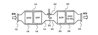
- FIG. 1 to 3 show an example of an exhaust emission control device.
- the exhaust purification device communicates the first casing 10 having a cylindrical shape, the second casing 20 having the same cylindrical shape, and the far ends of the first casing 10 and the second casing 20 with each other. And a communication pipe 30 to be configured.
- the axis 10A of the first housing 10 and the axis 20A of the second housing 20 may be substantially parallel (appearance parallel). .) Are arranged in close proximity to each other.
- the communication pipe 30 is arranged so that the axis 30 ⁇ / b> A of the communication pipe 30 is substantially parallel to the axis 10 ⁇ / b> A of the first casing 10 and the axis 20 ⁇ / b> A of the second casing 20.
- casing 20, and the communicating pipe 30 correspond to some exhaust pipes of an engine.
- casing 20, and the communicating pipe 30 are formed from ferritic stainless steel plates, such as SUS436L, which were excellent in workability and weldability.
- an inflow port 12 is formed at the exhaust upstream end, and an exhaust port 14 is formed at the exhaust downstream end.
- the inlet 12 is formed at the end face of the exhaust upstream end, and the outlet 14 is formed at the side of the exhaust downstream end.
- a DOC (Diesel Oxidation Catalyst) 16 that oxidizes at least NO (nitrogen monoxide) to NO 2 (nitrogen dioxide) and PM (Particulate Matter) are collected between the inlet 12 and the outlet 14.
- a diesel particulate filter (Diesel Particulate Filter, hereinafter referred to as “DPF”) 18 to be removed is housed with the DOC 16 disposed upstream of the exhaust.
- DPF diesel particulate filter
- an inflow port 22 is formed at the exhaust upstream end, and an exhaust port 24 is formed at the exhaust downstream end.
- both the inflow port 22 and the discharge port 24 are formed on the side surface of the end portion of the second housing 20.
- an SCR catalyst 26 selective reduction catalyst that selectively reduces and purifies NOx by receiving supply of ammonia as a reducing agent, and ammonia that has passed through the SCR catalyst 26.
- an oxidation catalyst 28 for oxidizing hydrogen are housed with the SCR catalyst 26 disposed upstream of the exhaust.
- the communication pipe 30 is the exhaust downstream downstream end of the first casing 10, which is the far ends of the first casing 10 and the second casing 20, in other words, the far ends positioned on opposite sides of each other.
- the inflow port 22 at the exhaust upstream end of the second housing 20 are in communication with each other. Accordingly, engine exhaust flows into the first housing 10 from the inlet 12, passes through the DOC 16 and the DPF 18, and enters the communication pipe 30 from the outlet 14.
- the exhaust gas that has entered the communication pipe 30 flows into the second housing 20 from the inlet 22 through the communication pipe 30, passes through the SCR catalyst 26 and the oxidation catalyst 28, and is discharged from the outlet 24.
- the That is, the exhaust passage extending from the first housing 10 to the second housing 20 via the communication pipe 30 is folded once by the communication pipe 30.
- the communication pipe 30 is a straight straight pipe having bent portions formed at both ends for connection between the outlet 14 of the first casing 10 and the inlet 22 of the second casing 20.
- the injection nozzle 32 is attached to the bent portion with respect to the discharge port 14.
- the injection nozzle 32 injects and supplies the urea aqueous solution into the linear pipe of the communication pipe 30. Thereby, the linear length required for the uniform diffusion of the urea aqueous solution into the exhaust gas is secured.
- a known diffusion member such as a mesh member may be installed in the communication pipe 30.
- the exhaust discharged from the engine flows to the DPF 18 while a part of NO is oxidized to NO 2 by the DOC 16.
- the DPF 18 PM in the exhaust gas is collected and removed, and the regeneration of the DPF 18 is performed by oxidizing the PM using NO 2 generated by the DOC 16.
- the urea aqueous solution injected from the injection nozzle 32 at a flow rate corresponding to the engine operating state is hydrolyzed using exhaust heat and water vapor in the exhaust, and converted into ammonia, hydrogen, and the like.
- This ammonia is known to be selectively reduced with NOx in the exhaust gas in the SCR catalyst 26 and purified to harmless components H 2 O (water) and N 2 (nitrogen gas).
- H 2 O water
- N 2 nitrogen gas
- the silhouette of the exhaust purification device is a compact size similar to a square muffler. Further, since the far ends of the first casing 10 and the second casing 20 are communicated with each other by the communication pipe 30, the first casing 10 and the first casing 10 and the second casing 20 are secured while ensuring the tube length necessary for uniform diffusion of the urea aqueous solution.
- the communication pipe 30 can be accommodated in the silhouette of the second housing 20, and the size in the length direction from the exhaust upstream to the downstream has been successfully reduced.
- the straight portion sandwiched between the bent portions of the communication pipe 30, that is, at least a part of the exhaust pipe positioned between the injection nozzle 32 and the SCR catalyst 26 improves the heat retaining property of the communication pipe 30, for example, from the injection nozzle 32.
- a double tube structure comprising an inner tube 34 and an outer tube 36 arranged substantially concentrically is formed.
- the inner tube 34 and the outer tube 36 are formed by, for example, forming a ferritic stainless steel plate such as SUS436L into a pipe shape and butt-welding the ends thereof by TIG (Tungsten Inert Gas) welding or the like.
- the welded portion 38 of the inner tube 34 and the outer tube 36 extends along the axial direction of the inner tube 34 and the outer tube 36.
- the inner tube 34 and the outer tube 36 are welded from the inside of the inner tube 34 and the outer tube 36 in order to suppress sensitization to ammonia and hydrogen, and the grain boundary of the welded portion 38 is fine on the inner peripheral surface. You may make it rough on an outer peripheral surface.
- the welded portion 38 of the inner tube 34 and the outer tube 36 In the welded portion 38 of the inner tube 34 and the outer tube 36, a tensile stress of 100 MPa or more remains due to welding, and stress cracking is likely to occur (satisfaction of the stress condition). Further, the welded portion 38 of the inner tube 34 and the outer tube 36 has a large metal crystal grain size on the surface due to the heat effect during welding, and chromium (Cr) carbide is precipitated at the crystal grain boundary, while the surrounding chromium Since the (Cr) concentration is lowered, sensitivity to ammonia and hydrogen is sensitized (material conditions are satisfied).
- the exhaust passage having a substantially annular cross section formed between the inner tube 34 and the outer tube 36 has a gentle exhaust flow compared to the inner space of the inner tube 34, 38 is exposed to ammonia and hydrogen for a long time (environmental conditions are satisfied).
- the welded portion 38 of the inner tube 34 and the outer tube 36 has a region where stress corrosion cracking is likely to occur (stress corrosion cracking) because environmental conditions, material conditions, and stress conditions are all established. It is located in the generation area), and the durability may be reduced.
- the durability of the welded portion 38 does not deteriorate so much.
- the steel balls are formed on the welded portions 38 of the inner tube 34 and the outer tube 36.
- the shot peening process using is performed. That is, after the ferritic stainless steel plate is formed into a pipe shape and welded, as shown in FIG. 6, the shot peening apparatus 40 is moved in the tube axis direction from the inside of the inner tube 34 and the outer tube 36 toward the welded portion 38. A shot peening process is performed on the welded portion 38 by firing a steel ball from the nozzle while moving to a position.
- the inner tube 34 and the outer tube 36 may be moved in the axial direction.
- the shot peening process is performed on the welded portion 38 of the inner tube 34 and the outer tube 36, the tensile residual stress of the welded portion 38 is changed to the compressive residual stress, and the stress condition that is one of the causes of the deterioration in durability is hardly satisfied.
- the shot peening treatment is preferably performed on at least the inner surfaces of the inner tube 34 and the outer tube 36 that are easily exposed to ammonia and hydrogen.
- the welded portion 38 of the inner tube 34 and the outer tube 36 is difficult to satisfy material conditions and tensile conditions that cause a decrease in durability. Therefore, even if the welded portion 38 is exposed to ammonia and hydrogen, stress corrosion is caused. It becomes difficult to locate in the crack generation region, and durability can be improved. At this time, although the compressive residual stress decreases when the temperature reaches 600 ° C., the metal crystal grain size of the welded portion 38 is stable even at 600 ° C., so that a decrease in durability can be suppressed even at high temperatures.
- the shot peening process may use a stainless steel ball made of a material similar to the inner tube 34 and the outer tube 36.
- the same material as the ferritic stainless steel balls such as SUS436L, in other words, the inner tube 34 and the outer tube 36 may be used.
- a diameter of 50 to 300 ⁇ m in order to reduce the metal crystal grain size on the surface of the welded portion 38 so that a desired effect can be exhibited.
- 0.05 to 0.3 mm steel balls are preferably used. That is, since the durability deterioration occurs from the surface of the welded portion 38, the effect of improving the durability by the shot peening process depends on the compressive residual stress on the outermost surface of the welded portion 38.
- the relationship between the diameter of the steel ball and the compressive residual stress according to the distance from the surface is as shown in FIG. 7 when the ferritic stainless steel ball is fired with high-pressure air and gas of 0.3 MPa or more. Referring to FIG.
- the diameter of the steel ball can be selected from 50 to 300 ⁇ m.
- the steel ball used in the shot peening process has a metal crystal grain size on the surface of the welded portion 38 of the inner tube 34 and the outer tube 36 that is comparable to the metal crystal grain size of the material of the inner tube 34 and the outer tube 36.
- the diameter may be selected as appropriate.
- the communication pipe 30 is not limited to a double pipe structure including the inner pipe 34 and the outer pipe 36, and may be a single pipe structure. Also in this case, since the material condition and the stress condition that cause a decrease in durability are difficult to be satisfied, the durability of the welded portion 38 can be improved.
- the exhaust purification device is not limited to the one shown in FIGS. 1 to 3, and as shown in FIG. 7, the first casing 10, the communication pipe 30, and the second casing 20 are substantially straight in this order.
- the structure may be arranged in a shape.
- the exhaust pipe to be improved in durability is not limited to the communication pipe 30 but may be other parts exposed to ammonia and hydrogen.
Landscapes
- Engineering & Computer Science (AREA)
- Chemical & Material Sciences (AREA)
- Mechanical Engineering (AREA)
- Combustion & Propulsion (AREA)
- General Engineering & Computer Science (AREA)
- Chemical Kinetics & Catalysis (AREA)
- Health & Medical Sciences (AREA)
- Toxicology (AREA)
- Organic Chemistry (AREA)
- Metallurgy (AREA)
- Materials Engineering (AREA)
- Crystallography & Structural Chemistry (AREA)
- Physics & Mathematics (AREA)
- Thermal Sciences (AREA)
- Exhaust Gas After Treatment (AREA)
- Exhaust Silencers (AREA)
Description
本発明は、排気管の耐久性向上方法及び排気浄化装置に関する。
エンジン排気中の窒素酸化物(NOx)を除去する触媒浄化システムとして、特開2005-226528号公報(特許文献1)に記載された排気浄化装置が提案されている。かかる排気浄化装置は、排気管に配設されたSCR(Selective Catalytic Reduction)触媒の排気上流に、エンジン運転状態に応じた尿素水溶液を噴射供給することで、SCR触媒においてNOxと尿素水溶液から生成されるアンモニアとを選択的に還元反応させ、NOxを無害成分に浄化する。
ところで、エンジンの排気管の少なくとも一部は、加工性及び溶接性に優れた、SUS436Lなどのフェライト系ステンレス鋼板から形成されることがある。この場合、フェライト系ステンレス鋼板をパイプ状に成形し、その端部を突き合わせ溶接することで、排気管が作り上げられる。
エンジンの排気管に噴射供給された尿素水溶液は、排気熱及び排気中の水蒸気を使用した加水分解により、金属に対する腐食性を有するアンモニア及び水素などを生成する。また、排気管の溶接部は、溶接により引張応力が残留し、応力割れが発生し易くなると共に、溶接熱により表面の金属結晶粒径が大きくなり、腐食成分に対する感受性が鋭敏化してしまう。
このため、排気管の溶接部は、応力割れが発生し易い環境に晒されると共に、引張残留応力及び腐食成分に対する感受性の鋭敏化の相乗効果によって、耐久性が低下するおそれがあった。
そこで、本発明は、排気管の溶接部の耐久性を向上させることができる、排気管の耐久性向上方法及び排気浄化装置を提供することを目的とする。
アンモニア及び水素を含む排気が通過する、フェライト系ステンレス鋼板からなる排気管の溶接部に、ショットピーニング処理を施す。
排気管の溶接部の引張残留応力が圧縮残留応力に変わると共に、溶接部の金属結晶粒径が小さくなるので、排気管の耐久性を向上させることができる。
以下、添付された図面を参照し、本発明を実施するための実施形態について詳述する。
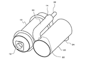
図1~図3は、排気浄化装置の一例を示す。
排気浄化装置は、筒形をなす第1の筐体10と、同じく筒形をなす第2の筐体20と、第1の筐体10及び第2の筐体20の遠端部同士を連通させる連通管30と、を含んで構成される。第1の筐体10と第2の筐体20とは、第1の筐体10の軸線10Aと第2の筐体20の軸線20Aとが略平行(見た目で平行という程度でよい。以下同様。)となるように、互いに並べて近接配置される。そして、連通管30の軸線30Aが第1の筐体10の軸線10A及び第2の筐体20の軸線20Aと略平行になるように、連通管30が配置される。ここで、第1の筐体10、第2の筐体20及び連通管30は、エンジンの排気管の一部に該当する。また、第1の筐体10、第2の筐体20及び連通管30は、加工性及び溶接性に優れた、SUS436Lなどのフェライト系ステンレス鋼板から形成されている。
図1~図3は、排気浄化装置の一例を示す。
排気浄化装置は、筒形をなす第1の筐体10と、同じく筒形をなす第2の筐体20と、第1の筐体10及び第2の筐体20の遠端部同士を連通させる連通管30と、を含んで構成される。第1の筐体10と第2の筐体20とは、第1の筐体10の軸線10Aと第2の筐体20の軸線20Aとが略平行(見た目で平行という程度でよい。以下同様。)となるように、互いに並べて近接配置される。そして、連通管30の軸線30Aが第1の筐体10の軸線10A及び第2の筐体20の軸線20Aと略平行になるように、連通管30が配置される。ここで、第1の筐体10、第2の筐体20及び連通管30は、エンジンの排気管の一部に該当する。また、第1の筐体10、第2の筐体20及び連通管30は、加工性及び溶接性に優れた、SUS436Lなどのフェライト系ステンレス鋼板から形成されている。
第1の筐体10では、排気上流端部に流入口12が形成され、排気下流端部に排出口14が形成される。本実施形態の場合、流入口12は排気上流端部の端面に形成され、排出口14は排気下流端部の側面に形成される。そして、流入口12と排出口14との間には、少なくともNO(一酸化窒素)をNO2(二酸化窒素)へと酸化させるDOC(Diesel Oxidation Catalyst)16と、PM(Particulate Matter)を捕集・除去するディーゼルパティキュレートフィルタ(Diesel Particulate Filter、以下「DPF」という。)18と、がDOC16を排気上流側に配置して収納される。
第2の筐体20では、排気上流端部に流入口22が形成され、排気下流端部に排出口24が形成される。本実施形態の場合、流入口22及び排出口24の両方とも、第2の筐体20の端部側面に形成される。そして、流入口22と排出口24との間には、還元剤としてのアンモニアの供給を受けてNOxを選択的に還元浄化するSCR触媒26(選択還元触媒)と、SCR触媒26を通過したアンモニア及び水素を酸化させる酸化触媒28と、がSCR触媒26を排気上流側に配置して収納される。
連通管30は、第1の筐体10及び第2の筐体20の遠端部同士、要するに、互いに反対側に位置する遠い方の端部である、第1の筐体10の排気下流端部の排出口14と、第2の筐体20の排気上流端部の流入口22と、を連通させる。従って、エンジンの排気は、流入口12から第1の筐体10に流入し、DOC16及びDPF18を通過して排出口14から連通管30の中へと入る。そして、連通管30の中へと入った排気は、連通管30を経て流入口22から第2の筐体20に流入し、SCR触媒26及び酸化触媒28を通過して排出口24から排出される。即ち、第1の筐体10から連通管30を経由して第2の筐体20へと至る排気の通路は、連通管30により一度折り返されている。
また、連通管30は、第1の筐体10の排出口14と第2の筐体20の流入口22との接続のために曲折部分が両端に形成された直線状の直管であって、排出口14に対する曲折部分に噴射ノズル32が取り付けられる。そして、噴射ノズル32は、連通管30の直線状の管内に向けて尿素水溶液を噴射供給する。これにより、排気中への尿素水溶液の均一拡散に必要な直線長さが確保されている。なお、尿素水溶液の均一拡散を促進するために、例えば、連通管30に網目部材など公知の拡散部材を設置してもよい。
かかる排気浄化装置において、エンジンから排出された排気は、DOC16により一部のNOがNO2へと酸化されつつ、DPF18へと流れる。DPF18では、排気中のPMが捕集・除去されると共に、DOC16により生成されたNO2を使用してPMが酸化されることで、DPF18の再生処理が行われる。
また、エンジン運転状態に応じた流量で噴射ノズル32から噴射された尿素水溶液は、排気熱及び排気中の水蒸気を使用して加水分解され、アンモニア及び水素などに転化される。このアンモニアは、SCR触媒26において排気中のNOxと選択的に還元反応し、無害成分であるH2O(水)及びN2(窒素ガス)へと浄化されることは知られたことである。一方、SCR触媒26を通過したアンモニア及び水素は、その排気下流に配設された酸化触媒28により酸化されるので、アンモニア及び水素がそのまま大気中に放出されることを抑制できる。
さらに、第1の筐体10と第2の筐体20とを近接させて並列に配置したため、排気浄化装置のシルエットは角型マフラー並みのコンパクトサイズとなっている。また、第1の筐体10及び第2の筐体20の遠端部同士を連通管30で連通させたため、尿素水溶液の均一拡散に必要な管長を確保しつつ、第1の筐体10及び第2の筐体20のシルエット内に連通管30を収めることが可能となり、排気上流から下流にかけての長さ方向のサイズを小さくすることに成功している。
連通管30の曲折部分により挟まれる直線部分、即ち、噴射ノズル32とSCR触媒26との間に位置する排気管の少なくとも一部は、連通管30の保温性を高め、例えば、噴射ノズル32から噴射供給された尿素水溶液の加水分解を促進するために、図4に示すように、略同心に配置された内管34及び外管36からなる二重管構造をなしている。内管34及び外管36は、例えば、SUS436Lなどのフェライト系ステンレス鋼板をパイプ状に成形し、その端部をTIG(Tungsten Inert Gas)溶接などで突き合わせ溶接することで作り上げられる。従って、内管34及び外管36の溶接部38は、内管34及び外管36の軸方向に沿って延びている。なお、内管34及び外管36は、アンモニア及び水素に対する感受性の鋭敏化を抑制すべく、内管34及び外管36の内方から溶接し、溶接部38の粒界が内周面で細かく外周面で粗くなるようにしてもよい。
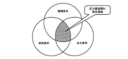
内管34及び外管36の溶接部38は、溶接により100MPa以上の引張応力が残留し、応力割れが発生し易くなっている(応力条件の成立)。また、内管34及び外管36の溶接部38は、溶接時の熱影響により表面の金属結晶粒径が大きくなり、結晶粒界にクロム(Cr)系炭化物が析出する一方、その周囲のクロム(Cr)濃度が低下するため、アンモニア及び水素に対する感受性が鋭敏化してしまう(材料条件の成立)。さらに、内管34と外管36との間に形成される略円環形状の横断面を有する排気通路は、内管34の内部空間と比較して排気の流れが緩やかであるため、溶接部38がアンモニア及び水素に晒される時間が長くなってしまう(環境条件の成立)。このため、内管34及び外管36の溶接部38は、図5に示すように、環境条件、材料条件及び応力条件が共に成立することで、応力腐食割れが発生し易い領域(応力腐食割れ発生領域)に位置するようになり、耐久性が低下するおそれがある。なお、環境条件、材料条件及び応力条件が共に成立しなければ、溶接部38の耐久性低下はさほど起こらない。
そこで、耐久性低下の原因となっている環境条件、材料条件及び応力条件のうち、材料条件及び応力条件が成立しないようにすべく、内管34及び外管36の溶接部38に、鋼球を使用したショットピーニング処理を施す。即ち、フェライト系ステンレス鋼板をパイプ状に成形して溶接した後、図6に示すように、内管34及び外管36の内方から溶接部38に向けて、ショットピーニング装置40を管軸方向に移動させながらノズルから鋼球を発射することで、溶接部38にショットピーニング処理を施す。ここで、ショットピーニング装置40を移動させる代わりに、内管34及び外管36を軸方向に移動させるようにしてもよい。内管34及び外管36の溶接部38にショットピーニング処理を施すと、溶接部38の引張残留応力が圧縮残留応力に変わり、耐久性低下の原因の1つとなっている応力条件が成立し難くなる。また、内管34及び外管36の溶接部38にショットピーニング処理を施すと、溶接部38の表面が鋼球に打たれることにより、その金属結晶粒径が小さくなって、耐久性低下の原因の他の1つとなっている材料条件が成立し難くなる。なお、ショットピーニング処理は、内管34及び外管36の内面及び外面のうち少なくとも、アンモニア及び水素に晒され易い内面に施すとよい。
従って、内管34及び外管36の溶接部38は、耐久性低下の原因となる材料条件及び引張条件が成立し難くなるため、この溶接部38がアンモニア及び水素に晒されても、応力腐食割れ発生領域に位置し難くなり、耐久性を向上させることができる。このとき、圧縮残留応力は600℃になると減少するが、溶接部38の金属結晶粒径は600℃でも安定しているため、高温下であっても耐久性低下を抑制することができる。
内管34及び外管36の溶接部38に、内管34及び外管36の材質とは異なる金属結晶が混入すると、溶接部38の表面における金属結晶粒径が大きくなり、アンモニア及び水素に対する感受性が鋭敏化し、材料条件が成立してしまう。そこで、ショットピーニング処理は、内管34及び外管36と類似の材質であるステンレス鋼球を使用するとよい。なお、ショットピーニング処理は、SUS436Lなどのフェライト系ステンレス鋼球、要するに、内管34及び外管36と同一の材質を使用してもよい。
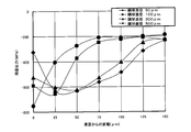
また、内管34及び外管36の溶接部38に対するショットピーニング処理においては、溶接部38の表面における金属結晶粒径を小さくして所望の効果を発揮できるようにすべく、直径50~300μm(0.05~0.3mm)の鋼球を使用するとよい。即ち、耐久性低下は溶接部38の表面から生じるため、ショットピーニング処理による耐久性向上の効果は、溶接部38の最表面における圧縮残留応力に依存する。鋼球の直径と表面からの距離に応じた圧縮残留応力との関係は、フェライト系ステンレス鋼球を0.3MPa以上の高圧空気,ガスで発射すると、図7に示すようになる。図7を参照すると、鋼球の直径が小さくなるにつれて、圧縮残留応力の最大値が最表面側に移動する一方、鋼球の直径が大きくなるにつれて、最表面は塑性変形により圧縮残留応力が小さくなり、圧縮残留応力の最大値が内部へと移動することが理解できる。従って、鋼球の直径としては、50~300μmを選定することができる。
なお、ショットピーニング処理で使用する鋼球は、内管34及び外管36の溶接部38の表面における金属結晶粒径が、内管34及び外管36の素材の金属結晶粒径と同程度となるように、その直径を適宜選定してもよい。
さらに、連通管30は、内管34及び外管36からなる二重管構造に限らず、一重の管構造であってもよい。この場合にも、耐久性低下の原因となる材料条件及び応力条件が成立し難くなるので、溶接部38の耐久性を向上させることができる。
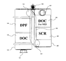
排気浄化装置としては、図1~図3に示す構造のものに限らず、図7に示すように、第1の筐体10、連通管30及び第2の筐体20がこの順番で略直線状に配置された構造であってもよい。また、耐久性を向上させる対象となる排気管は、連通管30に限らず、アンモニア及び水素に晒される他の部分であってもよい。
10 第1の筐体
20 第2の筐体
26 SCR触媒
30 連通管
32 噴射ノズル
34 内管
36 外管
38 溶接部
40 ショットピーニング装置
20 第2の筐体
26 SCR触媒
30 連通管
32 噴射ノズル
34 内管
36 外管
38 溶接部
40 ショットピーニング装置
Claims (5)
- アンモニア及び水素を含む排気が通過する、フェライト系ステンレス鋼板からなる排気管の溶接部に、ショットピーニング処理を施すことを特徴とする、排気管の耐久性向上方法。
- 前記ショットピーニング処理は、ステンレス鋼球を使用することを特徴とする、請求項1に記載の排気管の耐久性向上方法。
- 前記鋼球は、直径が50~300μmであることを特徴とする、請求項2に記載の排気管の耐久性向上方法。
- 前記ショットピーニング処理は、前記排気管の溶接部の内周面及び外周面のうち少なくとも内周面に施すことを特徴とする、請求項1に記載の排気管の耐久性向上方法。
- エンジンの排気管に配設され、尿素水溶液から生成されるアンモニアの供給を受けて、排気中の窒素酸化物を選択還元浄化する選択還元触媒と、
前記選択還元触媒の排気上流に尿素水溶液を噴射する噴射ノズルと、
を有し、
前記噴射ノズルと前記選択還元触媒との間に位置する排気管の少なくとも一部が、溶接部を有するフェライト系ステンレス鋼板からなり、前記排気管の溶接部にショットピーニング処理が施されていること
を特徴とする排気浄化装置。
Priority Applications (4)
| Application Number | Priority Date | Filing Date | Title |
|---|---|---|---|
| PCT/JP2012/064051 WO2013179435A1 (ja) | 2012-05-31 | 2012-05-31 | 排気管の耐久性向上方法及び排気浄化装置 |
| EP12878012.9A EP2868882A4 (en) | 2012-05-31 | 2012-05-31 | METHOD FOR IMPROVING THE DURABILITY OF AN EXHAUST GAS PIPE, AND EXHAUST GAS PURIFYING DEVICE |
| JP2014518166A JP5944989B2 (ja) | 2012-05-31 | 2012-05-31 | 排気管の耐久性向上方法 |
| US14/555,526 US9657362B2 (en) | 2012-05-31 | 2014-11-26 | Method for improving durability of exhaust pipe |
Applications Claiming Priority (1)
| Application Number | Priority Date | Filing Date | Title |
|---|---|---|---|
| PCT/JP2012/064051 WO2013179435A1 (ja) | 2012-05-31 | 2012-05-31 | 排気管の耐久性向上方法及び排気浄化装置 |
Related Child Applications (1)
| Application Number | Title | Priority Date | Filing Date |
|---|---|---|---|
| US14/555,526 Continuation US9657362B2 (en) | 2012-05-31 | 2014-11-26 | Method for improving durability of exhaust pipe |
Publications (1)
| Publication Number | Publication Date |
|---|---|
| WO2013179435A1 true WO2013179435A1 (ja) | 2013-12-05 |
Family
ID=49672689
Family Applications (1)
| Application Number | Title | Priority Date | Filing Date |
|---|---|---|---|
| PCT/JP2012/064051 Ceased WO2013179435A1 (ja) | 2012-05-31 | 2012-05-31 | 排気管の耐久性向上方法及び排気浄化装置 |
Country Status (4)
| Country | Link |
|---|---|
| US (1) | US9657362B2 (ja) |
| EP (1) | EP2868882A4 (ja) |
| JP (1) | JP5944989B2 (ja) |
| WO (1) | WO2013179435A1 (ja) |
Cited By (3)
| Publication number | Priority date | Publication date | Assignee | Title |
|---|---|---|---|---|
| CN104493727A (zh) * | 2014-12-23 | 2015-04-08 | 山东五岳钻具股份有限公司 | 一种石油钻杆内外壁抛丸强化、清理装置 |
| JP2015224754A (ja) * | 2014-05-29 | 2015-12-14 | 愛三工業株式会社 | 弁体と弁軸の固定方法 |
| CN113565606A (zh) * | 2021-08-31 | 2021-10-29 | 慈溪市汽车配件有限公司 | 一种汽车尾气处理用三元催化器 |
Families Citing this family (1)
| Publication number | Priority date | Publication date | Assignee | Title |
|---|---|---|---|---|
| CN107052534A (zh) * | 2017-01-12 | 2017-08-18 | 南京工程学院 | 一种同步喷丸镁合金焊接装置及方法 |
Citations (5)
| Publication number | Priority date | Publication date | Assignee | Title |
|---|---|---|---|---|
| JP2001198828A (ja) * | 2000-01-20 | 2001-07-24 | Nkk Corp | 耐食性に優れたステンレス鋼の製造方法 |
| JP2005226528A (ja) | 2004-02-12 | 2005-08-25 | Tokyo Roki Co Ltd | Scrマフラー |
| WO2007099949A1 (ja) * | 2006-03-02 | 2007-09-07 | Sumitomo Metal Industries, Ltd. | 耐水蒸気酸化性に優れた鋼管およびその製造方法 |
| JP2010116619A (ja) * | 2008-11-14 | 2010-05-27 | Nippon Steel & Sumikin Stainless Steel Corp | 加熱後耐食性に優れた自動車排気系部材用省Mo型フェライト系ステンレス鋼 |
| JP2011078968A (ja) * | 2009-09-24 | 2011-04-21 | Haldor Topsoe As | NOxのSCRのための方法及び触媒システム |
Family Cites Families (18)
| Publication number | Priority date | Publication date | Assignee | Title |
|---|---|---|---|---|
| JPS528930A (en) * | 1975-07-14 | 1977-01-24 | Nippon Kokan Kk | Method of preveting oxidation of austenite stainless steel due to highhtemperature steam |
| JPS56131083A (en) * | 1980-11-10 | 1981-10-14 | Hitachi Ltd | Welded joint method for stainless steel tube |
| JPS58107292A (ja) * | 1981-12-21 | 1983-06-25 | Kawasaki Heavy Ind Ltd | 管の溶接継手部処理方法及び装置 |
| JPH0696191B2 (ja) * | 1986-04-22 | 1994-11-30 | 月島機械株式会社 | フイン付チユ−ブの製造方法 |
| JP2618159B2 (ja) * | 1992-07-31 | 1997-06-11 | 日本発条株式会社 | 中空トーションバー |
| JP4331300B2 (ja) * | 1999-02-15 | 2009-09-16 | 日本発條株式会社 | 中空スタビライザの製造方法 |
| JP3820125B2 (ja) * | 2001-01-31 | 2006-09-13 | 三菱重工業株式会社 | 放射性物質を収納するキャニスタの製造方法 |
| JP2002282980A (ja) * | 2001-03-21 | 2002-10-02 | Calsonic Kansei Corp | 触媒コンバータの製造方法 |
| CA2390054C (en) * | 2002-06-28 | 2013-03-19 | Weatherford Canada Partnership | Method for manufacturing continuous sucker rod |
| US7032312B2 (en) * | 2002-07-16 | 2006-04-25 | Calsonickansei North America, Inc. | Catalytic converter and method for manufacture thereof |
| JP4441166B2 (ja) * | 2002-10-31 | 2010-03-31 | 新日本製鐵株式会社 | 鋼構造製品の環境助長割れ抵抗性向上方法 |
| JP4443910B2 (ja) * | 2003-12-12 | 2010-03-31 | Jfeスチール株式会社 | 自動車構造部材用鋼材およびその製造方法 |
| JP4703260B2 (ja) * | 2005-05-17 | 2011-06-15 | Udトラックス株式会社 | エンジンの排気浄化装置及びこれに用いられる排気管の構造 |
| US7402292B2 (en) * | 2005-09-19 | 2008-07-22 | Delphi Technologies, Inc. | Device and methods of ammonia generation for NOx abatement |
| JP2007278232A (ja) * | 2006-04-11 | 2007-10-25 | Matsuda Research Corporation:Kk | ディーゼルエンジン排ガスの浄化方法 |
| JP2008075543A (ja) * | 2006-09-21 | 2008-04-03 | Hino Motors Ltd | エンジンの排ガス浄化装置 |
| DE102008060151A1 (de) * | 2008-12-02 | 2010-06-10 | Bosch Mahle Turbo Systems Gmbh & Co. Kg | Verfahren zur Erhöhung der Verschleißfestigkeit |
| JP5912916B2 (ja) * | 2012-06-27 | 2016-04-27 | 日立Geニュークリア・エナジー株式会社 | ショットピーニング方法 |
-
2012
- 2012-05-31 WO PCT/JP2012/064051 patent/WO2013179435A1/ja not_active Ceased
- 2012-05-31 EP EP12878012.9A patent/EP2868882A4/en not_active Withdrawn
- 2012-05-31 JP JP2014518166A patent/JP5944989B2/ja not_active Expired - Fee Related
-
2014
- 2014-11-26 US US14/555,526 patent/US9657362B2/en not_active Expired - Fee Related
Patent Citations (5)
| Publication number | Priority date | Publication date | Assignee | Title |
|---|---|---|---|---|
| JP2001198828A (ja) * | 2000-01-20 | 2001-07-24 | Nkk Corp | 耐食性に優れたステンレス鋼の製造方法 |
| JP2005226528A (ja) | 2004-02-12 | 2005-08-25 | Tokyo Roki Co Ltd | Scrマフラー |
| WO2007099949A1 (ja) * | 2006-03-02 | 2007-09-07 | Sumitomo Metal Industries, Ltd. | 耐水蒸気酸化性に優れた鋼管およびその製造方法 |
| JP2010116619A (ja) * | 2008-11-14 | 2010-05-27 | Nippon Steel & Sumikin Stainless Steel Corp | 加熱後耐食性に優れた自動車排気系部材用省Mo型フェライト系ステンレス鋼 |
| JP2011078968A (ja) * | 2009-09-24 | 2011-04-21 | Haldor Topsoe As | NOxのSCRのための方法及び触媒システム |
Non-Patent Citations (1)
| Title |
|---|
| See also references of EP2868882A4 * |
Cited By (4)
| Publication number | Priority date | Publication date | Assignee | Title |
|---|---|---|---|---|
| JP2015224754A (ja) * | 2014-05-29 | 2015-12-14 | 愛三工業株式会社 | 弁体と弁軸の固定方法 |
| CN104493727A (zh) * | 2014-12-23 | 2015-04-08 | 山东五岳钻具股份有限公司 | 一种石油钻杆内外壁抛丸强化、清理装置 |
| CN113565606A (zh) * | 2021-08-31 | 2021-10-29 | 慈溪市汽车配件有限公司 | 一种汽车尾气处理用三元催化器 |
| CN113565606B (zh) * | 2021-08-31 | 2022-09-16 | 易典军 | 一种汽车尾气处理用三元催化器 |
Also Published As
| Publication number | Publication date |
|---|---|
| JP5944989B2 (ja) | 2016-07-05 |
| EP2868882A1 (en) | 2015-05-06 |
| EP2868882A4 (en) | 2016-05-18 |
| US9657362B2 (en) | 2017-05-23 |
| US20150082776A1 (en) | 2015-03-26 |
| JPWO2013179435A1 (ja) | 2016-01-14 |
Similar Documents
| Publication | Publication Date | Title |
|---|---|---|
| KR100890003B1 (ko) | 내연기관의 배기 가스 정화 장치 | |
| JP5602495B2 (ja) | 排気ガス浄化装置 | |
| JP4779959B2 (ja) | 排気浄化装置 | |
| JP4286887B2 (ja) | 排気浄化装置 | |
| CN104395578B (zh) | 用于排放物清洁模块的出口模块 | |
| KR101292627B1 (ko) | 배기 정화 장치 | |
| JP4930796B2 (ja) | 排気ガス浄化装置及びディーゼルエンジン用排気管 | |
| JP6000506B2 (ja) | 排気浄化装置 | |
| JP2012047109A (ja) | 排気ガス浄化装置 | |
| JP5944989B2 (ja) | 排気管の耐久性向上方法 | |
| JP4703260B2 (ja) | エンジンの排気浄化装置及びこれに用いられる排気管の構造 | |
| JP5555023B2 (ja) | 排気浄化装置 | |
| WO2013084653A1 (ja) | 排気浄化装置及び排気浄化装置の耐腐食性向上方法 | |
| JP6620639B2 (ja) | ディーゼル機関の排気処理システム | |
| JP2016109004A (ja) | 排気ガス浄化装置 | |
| CN103958844B (zh) | 排气净化装置和排气净化装置的耐腐蚀性提高方法 | |
| JP2015209799A (ja) | 内燃機関の排気浄化装置 | |
| KR102232267B1 (ko) | 질소산화물 저감장치 | |
| WO2017150513A1 (ja) | 内燃機関の排ガス浄化装置 | |
| JP2018071360A (ja) | 排気浄化装置 | |
| JP2021148076A (ja) | 管接合方法及び、管接合構造 | |
| JP2020204286A (ja) | パイプ保温構造 | |
| JP2020023914A (ja) | エンジンの排気後処理装置 | |
| JP2016200114A (ja) | 排出ガス浄化装置 | |
| JP2009097439A (ja) | 排気浄化装置 |
Legal Events
| Date | Code | Title | Description |
|---|---|---|---|
| 121 | Ep: the epo has been informed by wipo that ep was designated in this application |
Ref document number: 12878012 Country of ref document: EP Kind code of ref document: A1 |
|
| ENP | Entry into the national phase |
Ref document number: 2014518166 Country of ref document: JP Kind code of ref document: A |
|
| WWE | Wipo information: entry into national phase |
Ref document number: 2012878012 Country of ref document: EP |
|
| NENP | Non-entry into the national phase |
Ref country code: DE |