WO2013179686A1 - 超電導ケーブルのフォーマの接続構造及び接続方法 - Google Patents
超電導ケーブルのフォーマの接続構造及び接続方法 Download PDFInfo
- Publication number
- WO2013179686A1 WO2013179686A1 PCT/JP2013/051812 JP2013051812W WO2013179686A1 WO 2013179686 A1 WO2013179686 A1 WO 2013179686A1 JP 2013051812 W JP2013051812 W JP 2013051812W WO 2013179686 A1 WO2013179686 A1 WO 2013179686A1
- Authority
- WO
- WIPO (PCT)
- Prior art keywords
- former
- formers
- connection
- wedge
- hollow
- Prior art date
- Legal status (The legal status is an assumption and is not a legal conclusion. Google has not performed a legal analysis and makes no representation as to the accuracy of the status listed.)
- Ceased
Links
Images




Classifications
-
- H—ELECTRICITY
- H01—ELECTRIC ELEMENTS
- H01R—ELECTRICALLY-CONDUCTIVE CONNECTIONS; STRUCTURAL ASSOCIATIONS OF A PLURALITY OF MUTUALLY-INSULATED ELECTRICAL CONNECTING ELEMENTS; COUPLING DEVICES; CURRENT COLLECTORS
- H01R4/00—Electrically-conductive connections between two or more conductive members in direct contact, i.e. touching one another; Means for effecting or maintaining such contact; Electrically-conductive connections having two or more spaced connecting locations for conductors and using contact members penetrating insulation
- H01R4/58—Electrically-conductive connections between two or more conductive members in direct contact, i.e. touching one another; Means for effecting or maintaining such contact; Electrically-conductive connections having two or more spaced connecting locations for conductors and using contact members penetrating insulation characterised by the form or material of the contacting members
- H01R4/68—Connections to or between superconductive connectors
-
- H—ELECTRICITY
- H01—ELECTRIC ELEMENTS
- H01B—CABLES; CONDUCTORS; INSULATORS; SELECTION OF MATERIALS FOR THEIR CONDUCTIVE, INSULATING OR DIELECTRIC PROPERTIES
- H01B12/00—Superconductive or hyperconductive conductors, cables, or transmission lines
- H01B12/16—Superconductive or hyperconductive conductors, cables, or transmission lines characterised by cooling
-
- H—ELECTRICITY
- H01—ELECTRIC ELEMENTS
- H01B—CABLES; CONDUCTORS; INSULATORS; SELECTION OF MATERIALS FOR THEIR CONDUCTIVE, INSULATING OR DIELECTRIC PROPERTIES
- H01B13/00—Apparatus or processes specially adapted for manufacturing conductors or cables
- H01B13/0036—Details
-
- H—ELECTRICITY
- H01—ELECTRIC ELEMENTS
- H01R—ELECTRICALLY-CONDUCTIVE CONNECTIONS; STRUCTURAL ASSOCIATIONS OF A PLURALITY OF MUTUALLY-INSULATED ELECTRICAL CONNECTING ELEMENTS; COUPLING DEVICES; CURRENT COLLECTORS
- H01R4/00—Electrically-conductive connections between two or more conductive members in direct contact, i.e. touching one another; Means for effecting or maintaining such contact; Electrically-conductive connections having two or more spaced connecting locations for conductors and using contact members penetrating insulation
- H01R4/02—Soldered or welded connections
- H01R4/029—Welded connections
-
- H—ELECTRICITY
- H02—GENERATION; CONVERSION OR DISTRIBUTION OF ELECTRIC POWER
- H02G—INSTALLATION OF ELECTRIC CABLES OR LINES, OR OF COMBINED OPTICAL AND ELECTRIC CABLES OR LINES
- H02G1/00—Methods or apparatus specially adapted for installing, maintaining, repairing or dismantling electric cables or lines
- H02G1/14—Methods or apparatus specially adapted for installing, maintaining, repairing or dismantling electric cables or lines for joining or terminating cables
-
- H—ELECTRICITY
- H02—GENERATION; CONVERSION OR DISTRIBUTION OF ELECTRIC POWER
- H02G—INSTALLATION OF ELECTRIC CABLES OR LINES, OR OF COMBINED OPTICAL AND ELECTRIC CABLES OR LINES
- H02G15/00—Cable fittings
- H02G15/34—Cable fittings for cryogenic cables
-
- H—ELECTRICITY
- H10—SEMICONDUCTOR DEVICES; ELECTRIC SOLID-STATE DEVICES NOT OTHERWISE PROVIDED FOR
- H10N—ELECTRIC SOLID-STATE DEVICES NOT OTHERWISE PROVIDED FOR
- H10N60/00—Superconducting devices
- H10N60/80—Constructional details
-
- Y—GENERAL TAGGING OF NEW TECHNOLOGICAL DEVELOPMENTS; GENERAL TAGGING OF CROSS-SECTIONAL TECHNOLOGIES SPANNING OVER SEVERAL SECTIONS OF THE IPC; TECHNICAL SUBJECTS COVERED BY FORMER USPC CROSS-REFERENCE ART COLLECTIONS [XRACs] AND DIGESTS
- Y02—TECHNOLOGIES OR APPLICATIONS FOR MITIGATION OR ADAPTATION AGAINST CLIMATE CHANGE
- Y02E—REDUCTION OF GREENHOUSE GAS [GHG] EMISSIONS, RELATED TO ENERGY GENERATION, TRANSMISSION OR DISTRIBUTION
- Y02E40/00—Technologies for an efficient electrical power generation, transmission or distribution
- Y02E40/60—Superconducting electric elements or equipment; Power systems integrating superconducting elements or equipment
-
- Y—GENERAL TAGGING OF NEW TECHNOLOGICAL DEVELOPMENTS; GENERAL TAGGING OF CROSS-SECTIONAL TECHNOLOGIES SPANNING OVER SEVERAL SECTIONS OF THE IPC; TECHNICAL SUBJECTS COVERED BY FORMER USPC CROSS-REFERENCE ART COLLECTIONS [XRACs] AND DIGESTS
- Y10—TECHNICAL SUBJECTS COVERED BY FORMER USPC
- Y10T—TECHNICAL SUBJECTS COVERED BY FORMER US CLASSIFICATION
- Y10T29/00—Metal working
- Y10T29/49—Method of mechanical manufacture
- Y10T29/49002—Electrical device making
- Y10T29/49117—Conductor or circuit manufacturing
- Y10T29/49194—Assembling elongated conductors, e.g., splicing, etc.
-
- Y—GENERAL TAGGING OF NEW TECHNOLOGICAL DEVELOPMENTS; GENERAL TAGGING OF CROSS-SECTIONAL TECHNOLOGIES SPANNING OVER SEVERAL SECTIONS OF THE IPC; TECHNICAL SUBJECTS COVERED BY FORMER USPC CROSS-REFERENCE ART COLLECTIONS [XRACs] AND DIGESTS
- Y10—TECHNICAL SUBJECTS COVERED BY FORMER USPC
- Y10T—TECHNICAL SUBJECTS COVERED BY FORMER US CLASSIFICATION
- Y10T29/00—Metal working
- Y10T29/49—Method of mechanical manufacture
- Y10T29/49826—Assembling or joining
Definitions
- the present invention relates to a connecting structure and a connecting method for a former located at the center of a cable core of a superconducting cable.
- a superconducting cable includes a cable core having a former and a superconducting wire, and a heat insulation pipe having a vacuum double pipe structure that accommodates the cable core. Circulation of an ultra-low temperature liquid refrigerant for cooling the cable core is provided inside the heat insulation pipe. Is done. And in order to raise the cooling efficiency of a superconducting wire and a former, a former is formed in a hollow and a liquid refrigerant is circulated also in the hollow inside.
- Patent Document 3 As a method for connecting the joints of the hollow conductors, there is known a method (Patent Document 3) in which a reinforcing pipe is arranged on the outer periphery of the hollow conductor and the hollow conductor and the reinforcing pipe are brazed.
- An object of the present invention is to provide a connection structure and a connection method for a superconducting cable that enables good power transmission of the superconducting conductor layer while maintaining the hollow state of the former.
- the present invention is a connection structure for connecting hollow formers provided inside a superconducting cable, and has one end of a hollow connection conduit at an opening formed in a connection end of each of the formers and leading to a hollow interior. And the other end portion are inserted, and the connecting end portions of the formers in the opposed state are joined by welding.
- connection end portions of the formers are configured by end surfaces including inclined surfaces with respect to the longitudinal direction, and the corresponding inclined surfaces of the connection end portions of the formers are connected to each other. It is good also as a structure which has opposed so that a wedge-shaped clearance gap may be formed and between the said end surfaces which faced each other is joined by the filler material.
- the end surface includes two large and small inclined surfaces, and the two large and small wedge-shaped gaps formed by the inclined surfaces between the connection end portions of the formers in the opposed state.
- the larger wedge-shaped gap may be arranged on the upper side, and the smaller wedge-shaped gap may be arranged on the lower side, and the gaps may be filled with a filler material.
- the maximum opening width of the larger wedge-shaped gap in the longitudinal direction of the former is three times the maximum opening width of the smaller wedge-shaped gap in the longitudinal direction of the former. It is good also as a structure made into the above.
- connection structure may be configured such that each of the formers is formed by bundling copper strands, and the connection end is integrally solidified by a copper material.
- the present invention is a connection method for connecting hollow formers provided in superconducting cables to each other, wherein a hollow connection conduit is formed in an opening portion formed in a connection end of each of the formers and leading to a hollow interior.
- the method includes a step of inserting one end portion and the other end portion of the above and a step of joining the connecting end portions of the formers in an opposed state by welding.
- connection method includes a step of forming an end surface including an inclined surface with respect to the longitudinal direction of the connection end portion of each of the formers.
- connection end of each of the formers It is good also as a structure filled with the filler material between the said end surfaces which faced so that the said inclined surfaces where a part respond
- the present invention according to the connection method includes a detachable insertion aid used in a state of extending radially outward from an outer peripheral surface of the connection conduit, and one end of the connection conduit; In the step of inserting the other end portion, the insertion operation into the opening of each former of the connection conduit in a state where the insertion auxiliary tool extends outward from between the end faces of the respective connection end portions facing each other.
- the insertion assisting tool may be removed after insertion.
- an end surface composed of two large and small inclined surfaces is formed at the connecting end portion of each of the formers, and in the step of joining by the welding, each of the above-mentioned facing states is formed.
- the larger wedge-shaped gap is on the upper side
- the smaller wedge-shaped gap is on the lower side. It is good also as a structure which arrange
- connection method may be configured such that each of the formers is formed by bundling conductor strands, and includes a step of integrally fixing the connection end.
- the connecting end portions of the former are joined by welding in a state where the hollow connecting conduit is inserted into the opening portion leading to the hollow inside of the connecting end portion of each former, the liquid refrigerant for cooling the inside It is possible to perform the circulation of the above. Furthermore, since there is no concern of blocking the hollow interior of the former due to the presence of the connection conduit, the entire connection end face can be sufficiently bonded, and the bonding strength can be improved. Further, it is possible to prevent the hollow interior of the former from being blocked by the deformation of the members constituting the former by the connecting conduit during the joining operation. Furthermore, since there is no concern of blocking the hollow interior of the former due to the presence of the connecting conduit, the joining operation can be easily performed, and the workability can be improved.
- the maximum opening width in the longitudinal direction of the former of the larger wedge-shaped gap is more than three times the maximum opening width in the longitudinal direction of the former of the smaller wedge-shaped gap, the larger wedge-shaped When the filler material moves from the gap to the lower wedge-shaped gap, the filler material can be filled into the smaller wedge-shaped gap without shortage.
- the former when the former is formed by bundling conductor strands, the former itself can have high flexibility, and it becomes easy to abut the connecting ends thereof, thereby improving workability. Is possible.
- the connection end since the connection end is solidified integrally, the conductor wire constituting the former does not vary during the joining operation, it is possible to facilitate the joining operation and increase the joining strength. Connection resistance can also be lowered by integrating the cross section.
- the connecting conduit is provided with an insertion assisting tool extending from the outer peripheral surface toward the outside in the radial direction
- the inserting operation of the connecting conduit can be performed using the inserting assisting tool.
- the insertion assisting tool is detachable from the connecting conduit and can be removed after the insertion work, it does not interfere with the subsequent work. From this point, workability is improved. Yes.
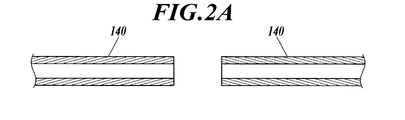
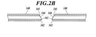
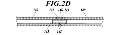
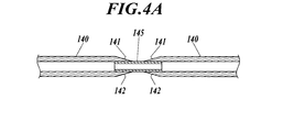
- FIG. 2A It is the figure which showed the connection operation process following FIG. 2A at the time of connecting a former. It is the figure which showed the connection operation process following FIG. 2B at the time of connecting a former. It is the figure which showed the connection operation process following FIG. 2C at the time of connecting a former. It is the figure which looked at the connection end part of one former in Drawing 2B from the other former side. It is a figure which shows the example at the time of forming the inclined surface equal in magnitude
- FIG. 1 is a diagram showing an example of a superconducting cable.
- the superconducting cable 10 is a single-core superconducting cable in which a single cable core 11 is accommodated in a heat insulating tube 12.
- the cable core 11 includes a former 140, a superconducting conductor layer 112 composed of superconducting wires, an electrical insulating layer 113, a superconducting shield layer 114, a normal conducting shield layer 115, a protective layer 116, and the like.
- the former 140 is a winding core for forming the cable core 11, and is formed by twisting normal conductive wires (conductor wires) such as copper wires. A fault current that flows in the superconducting conductor layer 112 in the case of a short-circuit fault is shunted to the former 140. Further, the former 140 has a hollow interior, and a liquid refrigerant (for example, liquid nitrogen) is supplied to the hollow portion formed in the hollow to cool the former 140 and the superconducting conductor layer 112. Is done.
- the liquid refrigerant is the same as that supplied around the cable core 11 in the heat insulating pipe 12 described later.
- the superconducting conductor layer 112 is formed by spirally winding a plurality of superconducting wires on a former 140 via carbon paper (not shown).
- the superconducting conductor layer 112 has a four-layer structure. A power transmission current flows through the superconducting conductor layer 112 during steady operation.
- the superconducting wire constituting the superconducting conductor layer 112 has, for example, a laminated structure in which an intermediate layer, a superconducting layer, a protective layer, and the like are sequentially formed on a tape-shaped metal substrate.
- an RE superconductor (RE: rare earth element) that becomes a superconducting state at a liquid nitrogen temperature or higher can be used.
- RE-based superconductor is an yttrium-based superconductor represented by the chemical formula YBa 2 Cu 3 O 7-y (hereinafter, Y-based superconductor). Further, it may be a tape-shaped superconducting wire in which a superconductor is formed in a metal matrix.
- a bismuth-based superconductor for example, the chemical formula Bi 2 Sr 2 CaCu 2 O 8 + ⁇ (Bi2212), Bi 2 Sr 2 Ca 2 Cu 3 O 10 + ⁇ (Bi2223) can be applied.
- ⁇ represents an oxygen nonstoichiometric amount.
- the electrical insulating layer 113 is made of insulating paper such as insulating paper, semi-synthetic paper in which insulating paper and polypropylene film are joined, and polymer nonwoven fabric tape, and is wound on the superconducting conductor layer 112 in a laminated state. It is formed.
- the superconducting shield layer 114 is formed by spirally winding a plurality of superconducting wires on the electrical insulating layer 113 via carbon paper (not shown).
- the superconducting shield layer 114 has a two-layer structure. In the superconducting shield layer 114, substantially the same current as the conductor current flows in reverse phase by electromagnetic induction during steady operation.
- a superconducting wire constituting the superconducting shield layer 114 can be the same as the superconducting conductor layer 112.
- the normal conductive shield layer 115 is formed by winding a normal conductive wire such as a copper wire on the superconductive shield layer 114.
- the normal conducting shield layer 115 is shunted with an accident current flowing in the superconducting shield layer 114 in the event of a short circuit accident.
- the protective layer 116 is made of, for example, insulating paper such as insulating paper or polymer nonwoven fabric, and is formed by winding on the normal conducting shield layer 115.
- the heat insulating tube 12 is a double member that includes the heat insulating inner tube 121 that accommodates the cable core 11 and is filled with a refrigerant (for example, liquid nitrogen), and the heat insulating outer tube 122 that is disposed so as to cover the outer periphery of the heat insulating inner tube 121. It has a tube structure.
- the heat insulating inner tube 121 and the heat insulating outer tube 122 are, for example, stainless corrugated tubes (corrugated tubes).
- a multilayer heat insulation layer (super insulation) 123 composed of a laminated body of polyethylene film vapor-deposited aluminum is interposed and kept in a vacuum state.
- pipe 122 is coat
- connection structure of former of superconducting cable When a long-distance cable is laid, the ends of the plurality of superconducting cables 10 are connected to each other through known intermediate connection portions.
- a connection structure for connecting the formers 140 and 140 when connecting the two superconducting cables 10 and 10 is illustrated.
- 2A to 2D show a connection work process when the formers 140 and 140 are connected.
- the end of the cable core 11 is drawn from the heat insulating tube 12, and the superconducting conductor layer 112, the electrical insulating layer 113, the superconducting shield layer 114, the normal conducting shield layer 115, the protective layer. It is assumed that 116 is stripped and the connection end of the former 140 is exposed.
- the formers 140, 140 connected to each other are initially formed from one flat surface whose end surface is perpendicular to the longitudinal direction. Then, as shown in FIG. 2B, two inclined surfaces are formed at the connecting end portions of these formers 140 (inclined surface forming step). As shown in FIG. 3, the end surface of the connection end portion of each former 140 is in a state constituted by these two inclined surfaces 141 and 142, and each former 140 has a boundary between the two inclined surfaces 141 and 142. The boundary portion 143 becomes a pointed shape protruding toward the other former 140 side.
- the upper inclined surface 141 is preferably formed so that the overall size thereof is larger than that of the lower inclined surface 142 in the vertical direction and the longitudinal direction of the former 140.
- the formers 140 and 140 are formed by twisting a plurality of copper strands as described above, the upper and lower inclined surfaces 141 and 142 are both made of a copper material in which the gap between the copper strands is melted. It is hardened so that the copper wire does not come apart.
- connection conduit 145 is inserted into each of the openings 144 leading to the hollow interior at the connection ends of the formers 140, and the boundary portions 143 and 143 are mutually connected. Are brought into a facing state in which they are abutted (connection conduit insertion step).
- the boundary portions 143 and 143 are preferably parallel and in contact with each other in terms of the same diameter connection, but may have a slight gap.
- the connecting conduit 145 is designed to have an outer diameter that substantially matches the inner diameter of the hollow former 140 and can be inserted from the opening 144.
- the connecting conduit 145 is formed of a hollow conductor over the entire length, and is preferably the same material as the material forming the former 140 in terms of joining compatibility at the time of welding. Specifically, when the former 140 is made of copper, a copper tubular body is preferably used as the connection conduit 145, and when the former 140 is made of stainless steel, a stainless steel tubular body is preferably used as the connection conduit 145. .
- the connection conduit 145 inserted into the former 140 has a structure that does not hinder the flow of the liquid refrigerant flowing from the hollow interior of one former 140 to the hollow interior of the other former 140. Therefore, it is desirable that the inner diameter of the connecting conduit 145 is large, but it is preferable to determine the inner diameter while ensuring a predetermined strength because the strength decreases as the wall thickness decreases.
- the connecting ends of the formers 140 and 140 are in a state in which the boundary surfaces 143 and 143 are in contact with each other with the inclined surfaces 141 and 141 facing upward, the upper end is between the connecting ends.
- a wedge-shaped gap space is formed between the inclined surfaces 141 and 141 and the lower inclined surfaces 142 and 142.
- the maximum opening width a (the longitudinal width of the former 140) of the upper wedge-shaped gap space is desirably about 3 to 4 times the maximum opening width b of the lower wedge-shaped gap space. . Here it is 3 times.
- the connecting end portions of the formers 140 and 140 are welded from above using a filler material 146 (welding process).
- the filler material 146 soldder, copper, etc.
- the filler material penetrates into the lower wedge-shaped gap space between the boundary portions 143 and 143, As a result, the filler material 146 is filled in both the upper wedge-shaped gap space and the lower wedge-shaped gap space.
- the entire outer peripheral surface of the exposed connection conduit 145, the upper inclined surfaces 141 and 141, and the lower inclined surfaces 142 and 142 are in close contact with the filler material 146, and the connecting end portions of the formers 140 and 140 are connected.
- the hollow conduits 145 are not blocked by the filler material 146 by the connecting conduit 145, and the state in which the hollow interiors communicate with each other is satisfactorily maintained. If the filler material 146 protrudes outward from the upper and lower wedge-shaped gaps, the excess portion of the filler material 146 is polished and polished so that the joining portion of the filler material 146 becomes equal to the outer diameter of the formers 140 and 140. It is preferable to remove the additive.
- the hollow connection conduits 145 are inserted into the openings 144 and 144 leading to the hollow interiors of the connection ends of the formers 140 and 140.
- the connecting ends of the formers 140, 140 are joined by welding using a filler material, so that the hollow interior of the formers 140, 140 is prevented from being blocked during the joining work, and the cooling liquid inside is prevented.
- the refrigerant can be circulated satisfactorily. Further, since there is no concern that the filler material blocks the hollow interior of the formers 140 and 140, the entire connection end face can be sufficiently joined, and the joining strength can be improved.
- the joining operation can be easily performed, and the workability can be improved. Furthermore, unlike the case where a cylindrical member is provided outside the formers 140 and 140 and joined, no convex portions are formed on the outer peripheral surfaces of the formers 140 and 140. Therefore, the superconducting conductor layer 112 is formed by the convex portions on the surface of the former 140. It is possible to eliminate the generation of stress on the superconducting wire and improve the durability and reliability of the superconducting wire. Moreover, even when a large current is passed, it is possible to avoid the concentration of electric field at the corners of the cylindrical conductor and maintain good insulation performance.
- the filler material is filled between the connecting ends of the formers 140, 140 in the opposed state with the larger wedge-shaped gap formed by the inclined surfaces 141, 141 as the upper side, the smaller wedge formed by the inclined surfaces 142, 142 is provided.
- the filler material is filled up to the gaps in the shape, and the filler material can be spread over the entire connection end portion, and it becomes possible to join firmly and improve the workability of joining.
- the maximum opening width a of the larger wedge-shaped gap in the longitudinal direction of the former 140 is set to be three times the maximum opening width b of the smaller wedge-shaped gap, the lower wedge-shaped gap is below the larger wedge-shaped gap.
- the filler material moves to the smaller wedge-shaped gap on the side, and the filler material can be filled into the smaller wedge-shaped gap without excess or deficiency.
- the formers 140 and 140 are formed by bundling conductor (copper) strands
- the formers 140 and 140 themselves can have high flexibility, and their connection ends can be abutted against each other. It becomes easy and workability can be improved.
- the connection end portion integrally the conductor strands constituting the former 140 do not vary during the joining operation, and the joining operation can be facilitated and the joining strength can be increased.
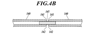
- connection structure of the formers 140 and 140 In the connection structure of the formers 140 and 140, the end surfaces of the two inclined surfaces 141 and 142 are formed at the respective connection end portions, thereby forming two large and small wedge-shaped gaps. However, these wedge-shaped gaps are formed. As shown in FIGS. 4A and 4B, they may be of uniform size. 4A shows a case where the inclination angles of the two inclined surfaces 141 and 142 with respect to the longitudinal direction of the former 140 are made equal and the inclination angle is made gentle, and FIG. 4B shows the two inclined surfaces 141 and 142 with respect to the longitudinal direction of the former 140. The case where the inclination angle is made equal and the inclination angle is made slightly larger than in the case of FIG. 4A is shown.
- the hollow interiors of the formers 140 and 140 are not blocked by the connection conduit 145, and it is possible to make a connection that maintains strong and excellent insulation, and it is possible to improve workability. It is. Further, during welding, the filler material can be filled from the upper wedge-shaped gap of the formers 140, 140 to the lower wedge-shaped gap, and the workability of joining can be improved.
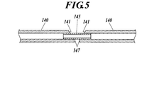
- an end surface composed of an inclined surface 141 and a vertical surface 147 perpendicular to the longitudinal direction of the former is formed at the connecting end portion of the formers 140, 140, and the inclined surfaces 141, 141 match each other.
- a wedge-shaped gap formed by the inclined surfaces 141 and 141 and a parallel gap formed by the vertical surfaces 147 and 147 are formed, and the filler is filled and joined with the wedge-shaped gaps facing upward. Also good.
- the connection conduit 145 does not block the hollow interior of each of the formers 140 and 140, making it possible to make a connection that maintains a strong and good insulation, and to improve workability. is there.
- the filler material filled in the wedge-shaped gap flows and fills the parallel gap side, so that the workability of joining can be improved.
- the parallel gap is smaller in volume than the wedge-shaped gap, so that it is possible to fill the parallel gap side with the filler material without excess or deficiency. . Therefore, while increasing the bonding strength, it is possible to suppress the filler material from protruding outside due to the excessive filling of the filler material into the lower gap, eliminating the need to remove excess filler material. Is possible. Further, since only one inclined surface 141 is formed on one former 140, it is possible to reduce the number of man-hours for connection work.
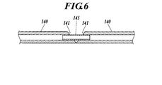
- connection conduit 145 does not block the hollow interior of each of the formers 140 and 140, making it possible to make a connection that maintains a strong and good insulation, and to improve workability. is there.
- only one inclined surface 141 is formed, it is possible to reduce the number of man-hours for connection work.
- only a wedge-shaped gap is formed between the connection ends of the formers 140 and 140. Therefore, it is necessary to perform the joining operation while adjusting the filling amount of the filler material so that the filled filler material does not leak to the lower side.
- the connecting end portions of the formers 140 and 140 may be only end surfaces perpendicular to the longitudinal direction of the former, and the connecting end portions of the formers 140 and 140 may be connected to each other by the connecting conduit 145.
- the connecting conduit 145 After one end of the connection conduit 145 is inserted into the opening 144 of one former 140 and fixed to each other by welding, the other end of the connection conduit 145 is inserted into the opening 144 of the other former 140.
- the opposing end surfaces of the formers 140 and 140 are connected by welding.
- the wedge-shaped gap space is not formed by the inclined surface, filling of the filler material into the space becomes unnecessary, and members of the formers 140 and 140 and the connecting conduit 145 are used without using the filler material. It is also possible to perform welding by melting a part of the metal. Moreover, welding using a small amount of filler material is also possible.
- the openings 144, 144 are inserted using the insertion aids 148 that can be attached to and detached from the recesses formed on the outer peripheral surface of the connection conduit 145.
- the connection conduit 145 may be inserted into (see FIG. 2B).
- the insertion aid 148 is attached in a state of extending radially outward from the outer peripheral surface of the connection conduit 145, and when inserting the connection conduit 145 into the openings 144, 144 of the formers 140, 140.
- a gap for example, a wedge-shaped gap
- the insertion aid 148 is operated to appropriately connect the connecting conduit 145 with respect to the longitudinal direction of the former 140. It is possible to adjust to the correct position. Since this insertion assisting tool 148 can be attached to and detached from the connection conduit 145, it can be removed and removed when the insertion process of the connection conduit 145 is completed. Therefore, the welding operation can be performed with the insertion assisting tool 148 removed. Further, the insertion assisting tool 148 is not attached to the former 140 as it is, and does not interfere with the formation of the superconducting conductor layer 112 on the outer periphery of the former 140. 7 shows the former 140 having the same connection end shape as that in FIG. 5, but the present invention is not limited to this, and any of the formers 140 in FIGS. 2C, 4A, 4B, and 6 can be connected. Is available.
Landscapes
- Physics & Mathematics (AREA)
- Condensed Matter Physics & Semiconductors (AREA)
- General Physics & Mathematics (AREA)
- Engineering & Computer Science (AREA)
- Manufacturing & Machinery (AREA)
- Superconductors And Manufacturing Methods Therefor (AREA)
- Gas Or Oil Filled Cable Accessories (AREA)
- Connections Effected By Soldering, Adhesion, Or Permanent Deformation (AREA)
- Manufacturing Of Electrical Connectors (AREA)
- Processing Of Terminals (AREA)
Abstract
Description
そして、超電導線及びフォーマの冷却効率を高めるために、フォーマを中空に形成し、その中空内部にも液体冷媒が循環されるようになっている。
そして、超電導ケーブルのフォーマの端部同士を連結する際には、先端部同士を突き合わせて溶接により接合したり(例えば、特許文献1参照)、筒状導体の両端からそれぞれのフォーマを挿入して、外部からかしめて連結したりする(例えば、特許文献2参照)などの方法が採られていた。
また、中空導体の継ぎ目を接続する方法として、中空導体の外周に補強パイプを配し、中空導体と補強パイプをロウ付けして接続する方法(特許文献3)が知られている。
また、筒状導体を用いてかしめやロウ付けによりフォーマを接続した場合、相互間の接触状態が不充分となって導電性が悪化する、或いは、フォーマの外側に配される超電導線に筒状導体の角部が当接して応力の発生原因となったり、筒状導体の角部において電界の集中が生じて絶縁性能が低下したりする等の問題が生じていた。
また、接合作業時に接続導管によってフォーマの中空内部がフォーマを構成する部材の変形によって塞がれることが防止される。更に、接続導管の存在によって、フォーマの中空内部を塞ぐ懸念がなくなるので、接合作業を容易に行うことができ、作業性の向上も図ることが可能となる。
そして、フォーマの外側に筒状部材を設ける場合と異なり、フォーマの外周面に凸状部分が生じないので、外周に超電導線を配した場合の応力を排除することができ、耐久性や信頼性の向上を図ることが可能となる。また、大電流を流した場合でも超電導線における電解の集中の発生を回避し、良好な絶縁性を維持することが可能となる。
また、接続端部は一体的に固められているので、接合作業時にフォーマを構成する導体素線がバラつくことがなく、接合作業を容易にすると共に接合強度を高めることが可能となり、更に、断面が一体化されていることで接続抵抗も低くすることができる。
以下、本発明の実施の形態を図面に基づいて詳細に説明する。
図1は超電導ケーブルの一例を示す図である。
超電導ケーブル10は、断熱管12内に一心のケーブルコア11が収納された単心型の超電導ケーブルである。ケーブルコア11は、フォーマ140、超電導線から構成される超電導導体層112、電気絶縁層113、超電導シールド層114、常電導シールド層115、保護層116等により構成される。
また、このフォーマ140は、内部が中空に形成されており、当該中空に形成された中空部には、当該フォーマ140及び超電導導体層112を冷却するために、液体冷媒(例えば液体窒素)が供給される。なお、この液体冷媒は後述する断熱管12内においてケーブルコア11の周囲に供給されるものと同一のものである。
超電導導体層112を構成する超電導線は、例えば、テープ状の金属基板上に中間層、超電導層、保護層等が順に形成された積層構造を有している。超電導層を構成する超電導体には、液体窒素温度以上で超電導状態となるRE系超電導体(RE:希土類元素)を用いることができる。RE系超電導体としては、例えば化学式YBa2Cu3O7-yで表されるイットリウム系超電導体(以下、Y系超電導体)が代表的である。また、金属マトリクス中に超電導体が形成されているテープ状の超電導線でもよい。超電導体には、ビスマス系超電導体、例えば化学式Bi2Sr2CaCu2O8+δ(Bi2212), Bi2Sr2Ca2Cu3O10+δ(Bi2223)を適用できる。
なお、化学式中のδは酸素不定比量を示す。
保護層116は、例えば、絶縁紙、高分子不織布などの絶縁性紙類で構成され、常電導シールド層115の上に巻回することにより形成される。
断熱内管121及び断熱外管122は、例えばステンレス製のコルゲート管(波付き管)である。断熱内管121と断熱外管122の間には、例えばアルミを蒸着したポリエチレンフィルムの積層体で構成された多層断熱層(スーパーインシュレーション)123が介在され、真空状態に保持される。また、断熱外管122の外周はポリ塩化ビニル(PVC)やポリエチレンなどで構成された防食層124で被覆されている。
長距離のケーブルが敷設される場合、複数の超電導ケーブル10の端部同士が既知の中間接続部を介してつなぎ合わせされることとなる。本実施形態では、二本の超電導ケーブル10、10をつなぎ合わせる際のフォーマ140,140同士を接続するための接続構造について例示する。
そして、図2Bに示すように、これら各フォーマ140の接続端部に二つの傾斜面を形成する(傾斜面形成工程)。各フォーマ140の接続端部の端面は、図3に示すように、これら二つの傾斜面141,142から構成された状態となり、各フォーマ140は、いずれも、二つの傾斜面141,142の境界となる境界部143が他方のフォーマ140側に突出した尖形の形状となる。なお、上側の傾斜面141は、上下方向及びフォーマ140の長手方向について全体的にその寸法が下側の傾斜面142よりも大きく形成されていることが好ましい。
なお、フォーマ140,140は、前述したように、複数の銅素線を撚り合わせて形成されているので、上下の傾斜面141,142では、いずれも銅素線の隙間を溶融した銅材で固めており、銅素線がばらけないようになっている。
なお、接続導管145は、中空のフォーマ140の内径と略一致し、開口部144から挿入可能な外径に設計されている。この接続導管145は、全長に渡って中空の導体で形成され、溶接の際の接合相性という点からフォーマ140を形成する材質と同じものが好ましい。具体的には、フォーマ140が銅製の場合には銅製の筒状体を接続導管145として用い、フォーマ140がステンレス鋼製の場合はステンレス鋼製の筒状体を接続導管145として用いるのが好ましい。フォーマ140に挿入された接続導管145は、一方のフォーマ140の中空内部から他方のフォーマ140の中空内部へと流れる液体冷媒の流通を阻害しない構造となっている。従って、接続導管145の内径は大きい方が望ましいが、その肉厚が薄くなると強度の低下を生じるため、所定の強度を確保しつつ内径を定めることがのぞましい。
これにより、露出した接続導管145の外周面、上側の各傾斜面141,141及び下側の各傾斜面142,142の全体が溶加材146に密着し、各フォーマ140,140の接続端部同士を強固に連結することができる。また、接続導管145により、各フォーマ140の中空内部が溶加材146で塞がれることなく、中空内部同士が連通した状態は良好に維持される。
なお、上下のくさび状の隙間空間から外側に溶加材146がはみ出た場合には、溶加材146による接合部分がフォーマ140,140の外径に等しくなるように、研磨して余分な溶加材は除去することが好ましい。
そして、超電導導体層112の上には、絶縁紙が巻回されて電気絶縁層113が形成される。このとき、半田接続された超電導線の接続部に対しては、より絶縁性を高める必要があるので、ケーブルコア11のもとの電気絶縁層113よりも外径が大きくなるまで絶縁紙が巻回される。
そして、電気絶縁層113の上には、互いに半田接続される超電導線が配置され、超電導シールド層114が形成され、さらに、その上に重ねて常電導シールド層115及び保護層116が形成される。
これにより、超電導ケーブル10,10のケーブルコア11,11が端部同士で接続される。さらに、各超電導ケーブル10,10のケーブルコア11,11の接続部は断熱容器に格納される。各超電導ケーブル10,10の断熱管12,12は、この接続部を収容した断熱容器に接続される。
その結果、断熱管12,12内に供給される液体冷媒は、断熱容器を介して、流通可能となり、ケーブルコア11,11の接続部における冷却手段も確保される。
また、溶加材がフォーマ140,140の中空内部を塞ぐ懸念がないので、十分に接続端面全体を接合させることができ、接合強度の向上を図ることが可能となる。また、溶加材がフォーマ140,140の中空内部を塞ぐ懸念がないので、接合作業を容易に行うことができ、作業性の向上も図ることが可能となる。
さらに、フォーマ140,140の外側に筒状部材を設けて接合する場合と異なり、フォーマ140,140の外周面に凸状部分が生じないので、フォーマ140表面の凸状部分による超電導導体層112の超電導線への応力の発生を解消し、超電導線の耐久性や信頼性の向上を図ることが可能となる。また、大電流を流した場合でも筒状導体の角部において電界の集中の発生を回避し、良好な絶縁性能を維持することが可能である。
このとき、大きい方のくさび状の隙間のフォーマ140の長手方向における最大開口幅aを小さい方のくさび状の隙間の最大開口幅bの3倍とした場合、大きい方のくさび状の隙間から下側の小さい方のくさび状の隙間に溶加材が移動して、小さい方のくさび状の隙間にも過不足なく溶加材を充填することができる。
また、接続端部は一体的に固めることで、接合作業時にフォーマ140を構成する導体素線がバラつくことがなく、接合作業を容易とすると共に接合強度を高めることが可能となる。なお、接続端部を一体的に固める場合、固める際に用いる材料は、溶接後の接続部において電気性能のバラツキを抑えるという点から、導体素線の材質と同じ材料を用いることが好ましい。
なお、上記フォーマ140,140の接続構造では、それぞれの接続端部に二つの傾斜面141,142による端面を形成し、これらによって大小二つのくさび状の隙間を形成したが、これらくさび状の隙間は、図4A及び図4Bに示すように、均一の大きさにしても良い。図4Aはフォーマ140の長手方向に対する二つの傾斜面141,142の傾斜角度を等しくすると共に傾斜角度を緩やかにした場合を示し、図4Bはフォーマ140の長手方向に対する二つの傾斜面141,142の傾斜角度を等しくすると共に傾斜角度を図4Aの場合よりもやや大きくした場合を示している。
これらの場合も、接続導管145により各フォーマ140,140の中空内部が塞がれることなく、強固に良好な絶縁性を維持する接続を行うことができ、また、作業性の向上を図ること可能である。
さらに、溶接の際に、フォーマ140,140の上側のくさび状の隙間から下側のくさび状の隙間に溶加材を充填することができ、接合の作業性の向上も可能である。
この場合も、接続導管145により各フォーマ140,140の中空内部が塞がれることなく、強固に良好な絶縁性を維持する接続を行うことができ、また、作業性の向上を図ること可能である。
さらに、くさび状の隙間を上に向けることにより、くさび状の隙間に充填した溶加材が平行な隙間側にも流れて充填され、接合の作業性を向上することが可能である。また、図4A及び図4Bの場合と異なり、くさび状の隙間に比べて平行な隙間はその容積が小さいので、過不足なく平行な隙間側への溶加材の充填を行うことが可能である。従って、接合強度を高めつつ、下側の隙間への過剰な溶加材の充填により外部に溶加材がはみ出てしまうことを抑制でき、余分な溶加材の除去作業なども不要とすることが可能となる。
また、一つのフォーマ140に傾斜面141は一つしか形成しないので接続作業の工数を低減することが可能である。
この場合も、接続導管145により各フォーマ140,140の中空内部が塞がれることなく、強固に良好な絶縁性を維持する接続を行うことができ、また、作業性の向上を図ること可能である。
なお、この場合も傾斜面141は一つしか形成しないので接続作業の工数を低減することが可能となるが、各フォーマ140,140の接続端部同士の間にはくさび状の隙間しか形成されないので、充填した溶加材がその下側に漏れでないように、溶加材の充填量を調整しつつ接合作業を行う必要がある。
なお、この場合、傾斜面によるくさび状の隙間空間が形成されないので、当該空間への溶加材の充填が不要となり、溶加材を使用せずに、フォーマ140,140や接続導管145の部材の一部分を溶融させて溶接を行うことも可能である。また、少量の溶加材を使用しての溶接も可能である。
この挿入補助具148は、接続導管145に対して着脱可能であるため、接続導管145の挿入工程の完了時には、取り外して除去することが可能である。従って、溶接作業の際には、挿入補助具148は除いた状態で作業が可能である。また、挿入補助具148がそのままフォーマ140に取り付けられた状態にならず、フォーマ140の外周に超電導導体層112を形成する際の邪魔とならないようになっている。
なお、図7では、接続端部形状が図5と同じフォーマ140を図示しているが、これに限らず、図2C,図4A,図4B,図6のいずれのフォーマ140の接続作業にも利用可能である。
11 ケーブルコア
12 断熱管
112 超電導導体層
113 電気絶縁層
114 超電導シールド層
115 常電導シールド層
116 保護層
140 フォーマ
141,142 傾斜面
144 開口部
145 接続導管
146 溶加材
147 垂直面
148 挿入補助具
Claims (10)
- 超電導ケーブルの内部に設けられた中空のフォーマ同士を接続する接続構造であって、
それぞれの前記フォーマの接続端部に形成された中空内部に通じる開口部に中空の接続導管の一端部と他端部とが挿入され、
対向状態としたそれぞれの前記フォーマの接続端部の間が溶接によって接合されたフォーマの接続構造。 - それぞれの前記フォーマの接続端部はその長手方向に対する傾斜面を含む端面で構成されており、
それぞれの前記フォーマの接続端部の対応する前記傾斜面同士がくさび状の隙間を形成するように対向しており、向かい合った前記端面の間が溶加材によって接合された請求項1記載のフォーマの接続構造。 - 前記端面は大小二つの傾斜面を含み、
対向状態としたそれぞれの前記フォーマの接続端部の間に前記傾斜面によって形成される大小二つのくさび状の隙間のうち、大きい方のくさび状の隙間が上側に、小さい方のくさび状の隙間が下側となるように配置され、当該各隙間が溶加材で充填された請求項2記載のフォーマの接続構造。 - 前記大きい方のくさび状の隙間の前記フォーマの長手方向における最大開口幅を前記小さい方のくさび状の隙間の前記フォーマの長手方向における最大開口幅の三倍以上としたことを特徴とする請求項3記載のフォーマの接続構造。
- それぞれの前記フォーマは導体素線を束ねて形成されており、前記接続端部は一体的に固められていることを特徴とする請求項1から4のいずれか一項に記載のフォーマの接続構造。
- 超電導ケーブルの内部に設けられた中空のフォーマ同士を接続する接続方法であって、
それぞれの前記フォーマの接続端部に形成された中空内部に通じる開口部に中空の接続導管の一端部と他端部とを挿入する工程と、
対向状態としたそれぞれの前記フォーマの接続端部の間を溶接によって接合する工程とを備えることを特徴とするフォーマの接続方法。 - それぞれの前記フォーマの接続端部はその長手方向に対する傾斜面を含む端面を形成する工程を備え、
前記溶接で接合する工程では、それぞれの前記フォーマの接続端部の対応する前記傾斜面同士がくさび状の隙間を形成するように対向させると共に向かい合った前記端面の間に溶加材を充填することを特徴とする請求項6記載のフォーマの接続方法。 - 前記接続導管に対してその外周面から半径方向外側に向かって延出された状態で使用する着脱可能な挿入補助具を備え、
前記接続導管の一端部と他端部とを挿入する工程では、当該挿入補助具が対向するそれぞれの前記接続端部の端面の間から外部に延出された状態で前記接続導管のそれぞれの前記フォーマの開口部に対する挿入作業を行い、挿入後は前記挿入補助具を除去することを特徴とする請求項7記載のフォーマの接続方法。 - 前記傾斜面を含む端面を形成する工程では、それぞれの前記フォーマの接続端部に大小二つの傾斜面からなる端面を形成し、
前記溶接で接合する工程では、対向状態としたそれぞれの前記フォーマの接続端部の間に前記傾斜面によって形成される大小二つのくさび状の隙間のうち、大きい方のくさび状の隙間が上側に、小さい方のくさび状の隙間が下側となるように配置し、当該各隙間を溶加材で充填することを特徴とする請求項7又は8記載のフォーマの接続方法。 - それぞれの前記フォーマは素線を束ねて形成されており、前記接続端部を一体的に固める工程を備えることを特徴とする請求項6から9のいずれか一項に記載のフォーマの接続方法。
Priority Applications (4)
| Application Number | Priority Date | Filing Date | Title |
|---|---|---|---|
| EP13797579.3A EP2728687A4 (en) | 2012-05-31 | 2013-01-29 | STRUCTURE AND METHOD FOR CONNECTING A MESH OF A SUPERCONDUCTING CABLE |
| JP2013555649A JP6062378B2 (ja) | 2012-05-31 | 2013-01-29 | 超電導ケーブルのフォーマの接続構造及び接続方法 |
| CN201380002397.1A CN103733453B (zh) | 2012-05-31 | 2013-01-29 | 超导电缆的骨架的连接结构和连接方法 |
| US14/235,031 US20150107867A1 (en) | 2012-05-31 | 2013-01-29 | Structure and method for connecting formers of superconducting cables |
Applications Claiming Priority (2)
| Application Number | Priority Date | Filing Date | Title |
|---|---|---|---|
| JP2012-123861 | 2012-05-31 | ||
| JP2012123861 | 2012-05-31 |
Publications (1)
| Publication Number | Publication Date |
|---|---|
| WO2013179686A1 true WO2013179686A1 (ja) | 2013-12-05 |
Family
ID=49672902
Family Applications (1)
| Application Number | Title | Priority Date | Filing Date |
|---|---|---|---|
| PCT/JP2013/051812 Ceased WO2013179686A1 (ja) | 2012-05-31 | 2013-01-29 | 超電導ケーブルのフォーマの接続構造及び接続方法 |
Country Status (5)
| Country | Link |
|---|---|
| US (1) | US20150107867A1 (ja) |
| EP (1) | EP2728687A4 (ja) |
| JP (1) | JP6062378B2 (ja) |
| CN (1) | CN103733453B (ja) |
| WO (1) | WO2013179686A1 (ja) |
Cited By (1)
| Publication number | Priority date | Publication date | Assignee | Title |
|---|---|---|---|---|
| CN108711802A (zh) * | 2018-04-09 | 2018-10-26 | 深圳市沃尔核材股份有限公司 | 一种连接两竖直连接管的方法 |
Families Citing this family (6)
| Publication number | Priority date | Publication date | Assignee | Title |
|---|---|---|---|---|
| CN104134921B (zh) * | 2014-07-17 | 2016-04-20 | 华北电力大学 | 一种冷绝缘高温超导电缆导体端部连接方法 |
| CN104134953B (zh) * | 2014-07-17 | 2016-07-27 | 华北电力大学 | 一种超导电缆骨架连接结构及连接方法 |
| US10317485B2 (en) * | 2016-10-28 | 2019-06-11 | General Electric Company | System and method for magnetic resonance imaging one or more subjects |
| US20190145570A1 (en) * | 2017-11-16 | 2019-05-16 | Saudi Arabian Oil Company | Corrosion-resistant piping and methods of manufacturing and using the same |
| CN108321556B (zh) * | 2017-12-11 | 2020-01-31 | 北京交通大学 | 超导电缆接头的焊接装置 |
| CN119069176B (zh) * | 2024-11-05 | 2025-02-25 | 清华大学 | 一种高温超导单元、接头及高温超导接头的制备方法 |
Citations (6)
| Publication number | Priority date | Publication date | Assignee | Title |
|---|---|---|---|---|
| JPH08138768A (ja) * | 1994-11-14 | 1996-05-31 | Sumitomo Electric Ind Ltd | 超電導ケーブルのジョイント |
| JPH11121059A (ja) * | 1997-10-20 | 1999-04-30 | Fujikura Ltd | 超電導ケーブル用中間接続部 |
| JP2006302674A (ja) | 2005-04-20 | 2006-11-02 | Sumitomo Electric Ind Ltd | 超電導ケーブルの端末処理方法 |
| JP2009136071A (ja) | 2007-11-29 | 2009-06-18 | Furukawa Electric Co Ltd:The | 超電導ケーブルの接続方法 |
| JP2010020968A (ja) * | 2008-07-09 | 2010-01-28 | Sumitomo Electric Ind Ltd | 超電導ケーブル用フォーマの接続方法、および超電導ケーブル用フォーマの接続構造 |
| JP2010092715A (ja) * | 2008-10-08 | 2010-04-22 | Sumitomo Electric Ind Ltd | 超電導ケーブル |
Family Cites Families (14)
| Publication number | Priority date | Publication date | Assignee | Title |
|---|---|---|---|---|
| US2125324A (en) * | 1935-04-01 | 1938-08-02 | Karl D Williams | Method of and coupling for pressure pipes |
| US2646995A (en) * | 1948-09-10 | 1953-07-28 | Roland J Thompson | Brazed joint with backing ring |
| US2963129A (en) * | 1954-12-09 | 1960-12-06 | Babcock & Wilcox Co | Dissimilar metal welded joint with protective overlay |
| US3032870A (en) * | 1959-06-18 | 1962-05-08 | North American Aviation Inc | Brazed joint and fabrication method |
| US3895432A (en) * | 1973-07-04 | 1975-07-22 | Siemens Ag | Method of electrically joining together two bimetal tubular superconductors |
| ES2106952T3 (es) * | 1992-05-07 | 1997-11-16 | Conri Rohrverbindungstechnik R | Union de tubos asi como manguito de soldar para una union de tubos de este tipo. |
| EP1646472B1 (en) * | 2003-07-21 | 2010-09-15 | Grant Prideco LP | Device with a pipe/connector weld joint configuration |
| KR100496995B1 (ko) * | 2003-09-29 | 2005-06-23 | 엘에스전선 주식회사 | 초전도 케이블의 접속구조 및 접속방법 |
| JP4609842B2 (ja) * | 2004-11-30 | 2011-01-12 | 古河電気工業株式会社 | 超電導導体及びその製造方法 |
| WO2006115754A2 (en) * | 2005-04-26 | 2006-11-02 | Exxonmobil Upstream Research Company | Apparatus and methods of improving riser weld fatigue |
| CN2887514Y (zh) * | 2006-02-21 | 2007-04-11 | 中国水利水电第七工程局机电安装分局 | 水电站压力引水钢管焊接结构 |
| JP5074150B2 (ja) * | 2007-10-24 | 2012-11-14 | オリンパスメディカルシステムズ株式会社 | 内視鏡用可撓管 |
| JP5197092B2 (ja) * | 2008-03-27 | 2013-05-15 | 古河電気工業株式会社 | 超電導ケーブルの接続構造体及び接続方法 |
| CN102101210A (zh) * | 2011-02-25 | 2011-06-22 | 首钢总公司 | 一种610MPa水电站压力钢管用高强钢焊接方法 |
-
2013
- 2013-01-29 US US14/235,031 patent/US20150107867A1/en not_active Abandoned
- 2013-01-29 CN CN201380002397.1A patent/CN103733453B/zh active Active
- 2013-01-29 WO PCT/JP2013/051812 patent/WO2013179686A1/ja not_active Ceased
- 2013-01-29 EP EP13797579.3A patent/EP2728687A4/en not_active Withdrawn
- 2013-01-29 JP JP2013555649A patent/JP6062378B2/ja not_active Expired - Fee Related
Patent Citations (6)
| Publication number | Priority date | Publication date | Assignee | Title |
|---|---|---|---|---|
| JPH08138768A (ja) * | 1994-11-14 | 1996-05-31 | Sumitomo Electric Ind Ltd | 超電導ケーブルのジョイント |
| JPH11121059A (ja) * | 1997-10-20 | 1999-04-30 | Fujikura Ltd | 超電導ケーブル用中間接続部 |
| JP2006302674A (ja) | 2005-04-20 | 2006-11-02 | Sumitomo Electric Ind Ltd | 超電導ケーブルの端末処理方法 |
| JP2009136071A (ja) | 2007-11-29 | 2009-06-18 | Furukawa Electric Co Ltd:The | 超電導ケーブルの接続方法 |
| JP2010020968A (ja) * | 2008-07-09 | 2010-01-28 | Sumitomo Electric Ind Ltd | 超電導ケーブル用フォーマの接続方法、および超電導ケーブル用フォーマの接続構造 |
| JP2010092715A (ja) * | 2008-10-08 | 2010-04-22 | Sumitomo Electric Ind Ltd | 超電導ケーブル |
Non-Patent Citations (1)
| Title |
|---|
| See also references of EP2728687A4 |
Cited By (2)
| Publication number | Priority date | Publication date | Assignee | Title |
|---|---|---|---|---|
| CN108711802A (zh) * | 2018-04-09 | 2018-10-26 | 深圳市沃尔核材股份有限公司 | 一种连接两竖直连接管的方法 |
| CN108711802B (zh) * | 2018-04-09 | 2024-01-09 | 深圳市沃尔核材股份有限公司 | 一种连接两竖直连接管的方法 |
Also Published As
| Publication number | Publication date |
|---|---|
| JP6062378B2 (ja) | 2017-01-18 |
| CN103733453A (zh) | 2014-04-16 |
| US20150107867A1 (en) | 2015-04-23 |
| EP2728687A1 (en) | 2014-05-07 |
| EP2728687A4 (en) | 2015-01-21 |
| JPWO2013179686A1 (ja) | 2016-01-18 |
| CN103733453B (zh) | 2018-02-13 |
Similar Documents
| Publication | Publication Date | Title |
|---|---|---|
| JP6062378B2 (ja) | 超電導ケーブルのフォーマの接続構造及び接続方法 | |
| KR100886341B1 (ko) | 초전도 케이블의 조인트 구조 | |
| CN100576371C (zh) | 多相超导电缆连接结构和多相超导电缆线 | |
| EP2168179B1 (en) | A superconducting element joint | |
| TWI336982B (en) | Joint of superconducting cable | |
| CN103718382B (zh) | 超导电缆的中间连接部 | |
| US8946125B2 (en) | Connection structure for superconductive cables, method for laying the same, and method for vacuuming connection structure for superconductive cables | |
| JP6210537B2 (ja) | 超電導ケーブルの接続構造、超電導ケーブル、超電導ケーブルの終端部の電流端子構造 | |
| JP2004265715A (ja) | 直流用超電導ケーブルの端末構造 | |
| US8594756B2 (en) | Superconducting element joint, a process for providing a superconducting element joint and a superconducting cable system | |
| MX2007009371A (es) | Estructura de union intermedia tipo ramificacion de cable superconductor. | |
| US20050067184A1 (en) | Jointing structure and jointing method for superconducting cable | |
| JP4751424B2 (ja) | 超電導ケーブルコアの接続構造 | |
| US7723616B2 (en) | Superconducting cable and DC transmission system incorporating the superconducting cable | |
| JP2006141186A (ja) | 超電導ケーブルの接続構造 | |
| JP4927794B2 (ja) | 超電導ケーブル用フォーマの接続方法、および超電導ケーブル用フォーマの接続構造 | |
| CN111697404B (zh) | 高压电缆锡纸接地引线冷连接法 | |
| JP2013178960A (ja) | 接続部材 | |
| JP2013140691A (ja) | 超電導ケーブルの中間接続構造及び超電導ケーブルの接続方法 | |
| HK1076192B (en) | Multiphase superconducting cable connection structure and multiphase superconducting cable line | |
| HK1067448B (en) | Terminal structure of direct electric current superconducting cable and dc superconducting cable line |
Legal Events
| Date | Code | Title | Description |
|---|---|---|---|
| ENP | Entry into the national phase |
Ref document number: 2013555649 Country of ref document: JP Kind code of ref document: A |
|
| 121 | Ep: the epo has been informed by wipo that ep was designated in this application |
Ref document number: 13797579 Country of ref document: EP Kind code of ref document: A1 |
|
| WWE | Wipo information: entry into national phase |
Ref document number: 14235031 Country of ref document: US |
|
| WWE | Wipo information: entry into national phase |
Ref document number: 2013797579 Country of ref document: EP |
|
| NENP | Non-entry into the national phase |
Ref country code: DE |