WO2013179695A1 - 旋回作業車 - Google Patents
旋回作業車 Download PDFInfo
- Publication number
- WO2013179695A1 WO2013179695A1 PCT/JP2013/053947 JP2013053947W WO2013179695A1 WO 2013179695 A1 WO2013179695 A1 WO 2013179695A1 JP 2013053947 W JP2013053947 W JP 2013053947W WO 2013179695 A1 WO2013179695 A1 WO 2013179695A1
- Authority
- WO
- WIPO (PCT)
- Prior art keywords
- monitor
- lever
- display surface
- driver
- seat
- Prior art date
- Legal status (The legal status is an assumption and is not a legal conclusion. Google has not performed a legal analysis and makes no representation as to the accuracy of the status listed.)
- Ceased
Links
Images


Classifications
-
- E—FIXED CONSTRUCTIONS
- E02—HYDRAULIC ENGINEERING; FOUNDATIONS; SOIL SHIFTING
- E02F—DREDGING; SOIL-SHIFTING
- E02F3/00—Dredgers; Soil-shifting machines
- E02F3/04—Dredgers; Soil-shifting machines mechanically-driven
- E02F3/28—Dredgers; Soil-shifting machines mechanically-driven with digging tools mounted on a dipper- or bucket-arm, i.e. there is either one arm or a pair of arms, e.g. dippers, buckets
- E02F3/30—Dredgers; Soil-shifting machines mechanically-driven with digging tools mounted on a dipper- or bucket-arm, i.e. there is either one arm or a pair of arms, e.g. dippers, buckets with a dipper-arm pivoted on a cantilever beam, i.e. boom
- E02F3/32—Dredgers; Soil-shifting machines mechanically-driven with digging tools mounted on a dipper- or bucket-arm, i.e. there is either one arm or a pair of arms, e.g. dippers, buckets with a dipper-arm pivoted on a cantilever beam, i.e. boom working downwardly and towards the machine, e.g. with backhoes
- E02F3/325—Backhoes of the miniature type
-
- E—FIXED CONSTRUCTIONS
- E02—HYDRAULIC ENGINEERING; FOUNDATIONS; SOIL SHIFTING
- E02F—DREDGING; SOIL-SHIFTING
- E02F9/00—Component parts of dredgers or soil-shifting machines, not restricted to one of the kinds covered by groups E02F3/00 - E02F7/00
- E02F9/08—Superstructures; Supports for superstructures
- E02F9/0858—Arrangement of component parts installed on superstructures not otherwise provided for, e.g. electric components, fenders, air-conditioning units
-
- E—FIXED CONSTRUCTIONS
- E02—HYDRAULIC ENGINEERING; FOUNDATIONS; SOIL SHIFTING
- E02F—DREDGING; SOIL-SHIFTING
- E02F9/00—Component parts of dredgers or soil-shifting machines, not restricted to one of the kinds covered by groups E02F3/00 - E02F7/00
- E02F9/16—Cabins, platforms, or the like, for drivers
-
- E—FIXED CONSTRUCTIONS
- E02—HYDRAULIC ENGINEERING; FOUNDATIONS; SOIL SHIFTING
- E02F—DREDGING; SOIL-SHIFTING
- E02F9/00—Component parts of dredgers or soil-shifting machines, not restricted to one of the kinds covered by groups E02F3/00 - E02F7/00
- E02F9/20—Drives; Control devices
- E02F9/2004—Control mechanisms, e.g. control levers
-
- E—FIXED CONSTRUCTIONS
- E02—HYDRAULIC ENGINEERING; FOUNDATIONS; SOIL SHIFTING
- E02F—DREDGING; SOIL-SHIFTING
- E02F9/00—Component parts of dredgers or soil-shifting machines, not restricted to one of the kinds covered by groups E02F3/00 - E02F7/00
- E02F9/26—Indicating devices
Definitions
- the present invention relates to a turning work vehicle, and more particularly to a monitor arrangement structure for a turning work vehicle.
- Patent Document 1 there is one disclosed in Patent Document 1 as one form of a monitor arrangement structure of a turning work vehicle. That is, in Patent Document 1, a driver's seat is disposed in a driver disposed on a revolving structure, a lever support case is disposed on the right side of the driver's seat, and the working unit is operated on the front of the lever support case. There is disclosed a monitor arrangement structure in which a working unit operation lever is provided and a monitor for displaying various information is arranged at the rear end of the lever support case.
- the monitor is arranged at the rear end of the lever support case in the above-described monitor arrangement structure, the arrangement position of the monitor is located below the right arm of the worker holding the working unit operation lever. As a result, it was impossible to see the monitor while looking at the front and operating the lever. That is, there is a problem that the lever operation and the monitor confirmation operation cannot be performed simultaneously.
- an object of the present invention is to provide a turning work vehicle capable of simultaneously performing a lever operation and a monitor checking operation.
- a turning work vehicle wherein a driver's seat is disposed in a driving part disposed on a turning body, and a working part operation lever that operates the working part on either one of the left and right sides of the driver's seat;
- This is a monitor installation structure of a turning work vehicle provided with a monitor for displaying various information, and the monitor is arranged in front of the working part operation lever arranged in an upright manner, and is seated on the driver's seat so that the front is
- the display surface is directed to the viewpoint side of the worker who operates while visually recognizing, and the outer operation lever is arranged upright on the rear side of the monitor, and passes between the outer operation lever and the working unit operation lever in the worker's field of view.
- the display surface of the monitor can be seen.
- the display surface of the monitor oriented toward the operator's viewpoint through the outer operation lever and the operation unit operation lever within the field of view of the operator who sits in the driver's seat and operates while looking forward. Therefore, the operator can firmly see the display surface of the monitor while operating the working unit operation lever or the outer operation lever. As a result, work efficiency can be improved while ensuring safety during work.
- a turning work vehicle is the turning work vehicle according to the first aspect of the invention, wherein the upper end portion of the working portion operation lever, the upper end portion of the outer operation lever, and the central portion of the display surface of the monitor Are placed one side outward from the driver's seat, and the height from the floor of the driving unit is arranged at a low position, the center of the display surface of the monitor, the upper end of the working unit operating lever, and the outer operating lever The upper end of the monitor is sequentially arranged from the front to the rear, and the display surface of the monitor arranged on the lower outside through the space between the outer operation lever and the work unit operation lever can be seen in the operator's field of view. To do.
- a turning work vehicle according to the invention described in claim 3 is the turning work vehicle according to claim 1 or 2, wherein a monitor operation switch is provided near the display surface of the monitor, and the monitor operation switch is provided in the driver's seat.
- the operator who is seated on the arm extends between his / her working part operation lever and the outer operation lever and can be operated.
- a turning work vehicle is the turning working vehicle according to any one of the first to third aspects, wherein the monitor has a viewing angle of a fixed angle in the front-rear direction and the left-right direction, respectively.
- the display surface of the liquid crystal display is used so that the viewpoint of the worker seated in the driver's seat is always placed in the quadrangular pyramid-shaped viewing area formed by the viewing angles in the front-rear and left-right directions. It is characterized in that it is arranged to face the worker side.
- the display surface of the liquid crystal display is operated so that the viewpoint of the worker seated in the driver's seat is always placed in the quadrangular pyramid-shaped viewing area formed by the viewing angles in the front-rear and left-right directions.
- the constant visual field area can cover (cover) the operator's viewpoint. Therefore, even when the operator appropriately moves and adjusts the driver's seat to a desired position, the display surface of the liquid crystal display is firmly kept within the field of view, and the operator's visibility is ensured well.
- the viewing angle in the front-rear direction can be set to, for example, 50 degrees (25 degrees forward and 25 degrees backward) in the front-rear direction of the virtual reference line raised from the focal point.
- the display surface of the liquid crystal display is disposed slightly forward (for example, 5 degrees) so that the operator can easily see the display surface of the liquid crystal display.
- the viewing angle in the left-right direction can be set to, for example, 50 degrees (25 degrees to the left and 25 degrees to the right) in the left-right direction of the virtual reference line raised from the focal point.
- the operator can firmly see the display surface of the monitor while operating the operation part operation lever or the outer operation lever, and the work efficiency is improved while ensuring safety during work. The effect that it can be produced.
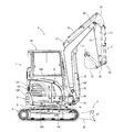
- the rear view of the turning working vehicle (excavation working vehicle) which concerns on this invention.
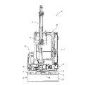
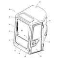
- the front view of a cabin The rear view of a cabin.
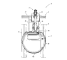
- operation part Sectional side explanatory drawing of a driving
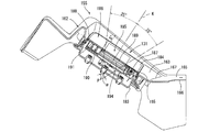
- the perspective explanatory view of an operation panel part Plane explanatory drawing of an operation panel part. Back side diagonal of right lever support case
- the perspective explanatory view of the operation panel part as other embodiments.
- Cross-sectional side explanatory drawing of the operation part as other embodiments. Plane explanatory drawing of the operation panel part as other embodiment.
- FIGS. 1 to 7 A shown in FIGS. 1 to 7 is an excavation work vehicle as a turning work vehicle according to the present invention.
- the excavation work vehicle A includes a traveling machine body 1 capable of self-propelling, an excavation part 2 as a working part attached to the traveling machine body 1, and a soil discharging part 3.
- the excavating bucket 13 is attached as a working attachment to the tip of the working unit to form the excavating unit 2.
- the traveling machine body 1 can move straight forward and backward by turning the pair of left and right crawler-type traveling parts 4 and 4 forward and backward, respectively, and can also turn and turn in the front and rear and left and right directions. -It is also possible to rotate the right traveling parts 4, 4 in directions opposite to each other to make a sharp turn.
- a base 5 is interposed between the traveling units 4, 4, and a revolving body 6 is rotatably mounted on the base 5.
- the swivel body 6 is capable of swiveling in either the left or right direction around the vertical axis of the central portion.
- the swivel body 6 is formed in a substantially disc shape in plan view that can swivel within the left and right widths of the travel parts 4, 4 (the distance between the outer edge of the left travel part 4 and the outer edge of the right travel part 4). is doing.
- the operation part 7 and the tank part 8 are arranged in the first half part, while the function part 9 is arranged in the second half part, and the operation part 7 and the function part 9 are arranged. Is enclosed by a cabin 30 described later.
- the excavation part stay 10 protrudes forward at a position near one side (in the present embodiment, right side) of the revolving body 6, and the base end part of the excavation part 2 is pivotally supported by the excavation part stay 10. It is attached.
- the earth removal part 3 is attached to the base 5 between the pair of left and right traveling parts 4, 4.
- the excavation unit 2 includes a boom 11, an arm 12, a bucket 13, and a swing cylinder 14, a boom cylinder 15, an arm cylinder 16, and a bucket cylinder 17 that rotate them.
- the excavation part stay 10 projecting to the right side of the front end portion of the revolving unit 6 is pivotally supported by a pivot 23 whose axis is directed in the vertical direction.
- a rocking body 18 is attached to the center so as to be able to rock right and left.
- a swing cylinder 14 that expands and contracts in the front-rear direction is interposed between the right middle part of the swing body 6 and the right front part of the swing body 18, and the swing body 18 swings in conjunction with the expansion and contraction operation of the swing cylinder 14. (Swivel from side to side) to operate.
- the rocking body 18 is pivotally supported by a first pivot 19 that is bent in the shape of a “he” in a side view and extends in the vertical direction by a first pivot 19 having an axis line in the left-right direction.
- a boom 11 is attached so as to be pivotable up and down about 19.
- a boom cylinder 15 that extends and contracts in the vertical direction is interposed between the front end portion of the rocking body 18 and the middle part of the front surface of the boom 11, and the boom 11 is vertically rotated in conjunction with the expansion and contraction operation of the boom cylinder 15.
- a first pivot 19 that is bent in the shape of a “he” in a side view and extends in the vertical direction by a first pivot 19 having an axis line in the left-right direction.
- a boom 11 is attached so as to be pivotable up and down about 19.
- a boom cylinder 15 that extends and contracts in the vertical direction is interposed between the front end portion of the rocking body 18 and the middle part of the front surface of the boom 11, and the boom
- the base end portion of the arm 12 extending in the vertical direction is pivotally supported at the distal end portion of the boom 11 by the second pivot 20 having the axis line in the left-right direction, and the arm 12 is moved back and forth around the second pivot 20. It is attached so that it can rotate freely (up and down).
- An arm cylinder 16 extending in the front-rear direction is interposed between the first cylinder mounting body 21 attached to the middle part of the upper surface of the boom 11 and the second cylinder mounting body 22 attached to the front base end of the arm 12.
- the arm 12 is rotated back and forth in conjunction with the expansion and contraction operation of the arm cylinder 16.
- the base of the bucket 13 is pivotally supported by a third pivot 25 whose axis is directed in the left-right direction, and the bucket 13 is pivotable back and forth around the third pivot 25 (up and down pivotable).
- a bucket link 24 is provided between the tip of the arm 12 and the base of the bucket 13, and a bucket cylinder that extends vertically between the bucket link 24 and the second cylinder mounting body 22 of the arm 12. 17, the bucket 13 is operated to rotate back and forth (up and down) in conjunction with the expansion and contraction operation of the bucket cylinder 17.
- the earth removal portion 3 can move up and down the base end portions of the pair of left and right blade arms 26, 26 extending in the front-rear direction to the base 5 between the pair of left and right traveling portions 4.
- a blade (soil removal plate) 27 extending in the left-right direction is installed between the tip portions of the blade arms 26 and 26.
- the blade 27 is formed to have substantially the same width as the width on the left and right sides of the running portions 4 and 4.
- Reference numeral 28 denotes a blade cylinder.
- the traveling machine body 1 is configured so that the traveling unit 4 is operated by the driving unit 7 so as to be able to perform straight forward traveling and left / right turning traveling as appropriate.
- work can be performed by operating the excavation part 2 with the operation part 7.
- the earthing work can be performed by operating the earthing unit 3 with the operation unit 7.
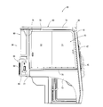
- the cabin 30 is mounted on the revolving structure 6 and surrounds the operation unit 7 and the function unit 9 except the tank unit 8. That is, as shown in FIGS. 8 to 13, the cabin 30 is formed in a box shape having a lower surface opening from a front wall portion 31, a left wall portion 32, a right wall portion 33, a rear wall portion 34, and a ceiling portion 35. Yes.
- the front wall portion 31 is provided with a horizontally elongated rectangular lower front wall body 42 extending in the left-right direction between the lower side portions of the pair of left and right front pillar bodies 40, 41 extending in the vertical direction.
- a front glass frame 43 having a vertically long rectangular frame shape is installed between upper portions of the front pillars 40 and 41, and a windshield 44 is stretched over the front glass frame 43. 45 is a wiper.
- the pair of left and right front pillars 40 and 41 are formed in a rearwardly inclined shape with a front height and a rear height, and are formed by bending the lower part in a forwardly inclined shape with a front height and a rear height.
- the windshield 44 is stretched in a rearwardly inclined manner, and the lower front wall body 42 below is stretched in a forwardly inclined manner.
- Reference numeral 46 denotes a front upper horizontal member that is extended between the upper end portions of the pair of left and right front column bodies 40 and 41 in the left-right direction, and 47 is a handrail attached to the left front column body 40.
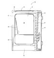
- the left side wall part 32 is formed of a front half side wall part 50 and a rear half side wall part 51.
- the front half side wall 50 is formed of a door frame 52 and an opening / closing door 53 attached to the door frame 52 so as to be freely opened and closed.
- the door frame 52 includes a left front column 40, a front half upper horizontal member 54 formed by extending horizontally from the upper end of the left front column 40 rearward outward, and a rear end of the front upper upper horizontal member 54.
- a left side view frame shape is formed from the lower lateral member 56.
- the open / close door 53 forms an outer shape along the inner peripheral edge of the door frame 52, and the rear edge of the open / close door 53 is pivotally supported on the midway column 55 via upper and lower hinges 57, 57. They are connected and can be opened and closed by pivoting the front edge portion side of the opening / closing door 53 around the pivot / connecting portion.
- the rear half side wall portion 51 of the left side wall portion 32 is horizontally extended rearward inward from the upper end portion of the intermediate column body 55 to form the rear half upper horizontal member 58, and vertically extends at the rear end portion of the rear half upper side horizontal member 58.
- the upper left end of the left rear column 59 extending is connected, and the left rear glass window 60 is stretched over most of the inner peripheral edge of the mid column 55, the rear upper horizontal member 58, and the left rear column 59, and A door opening receptacle 61 is stretched at the lower edge of the left rear glass window 60.
- a lower left edge wall 62 formed in a bowl shape is stretched along the lower edge of the door opening receptacle 61 and the lower half rear edge of the intermediate column 55. .
- the right side wall 33 is attached to the upper part of the right side wall forming frame 69 through the window frame 70 so that the front and rear glass windows 71 and 72 are slidable in the front-rear direction.
- a lower right edge wall 73 is stretched at the lower part of the body 69.
- the right wall forming frame 69 has a right upper horizontal member 74 formed by horizontally extending rightward from the right end of the front upper horizontal member 46 and an upper end connected to the rear end of the right upper horizontal member 74.
- Upper part from right rear column 75 extending in the vertical direction and right middle horizontal member 76 extending between the lower part of right rear column 75 and the middle part of right front column 41 and extending in the front-rear direction Is formed in a frame shape.
- the right rear column body 75 and the left rear column body 59 are arranged to face each other in the left-right direction, and a rear lower horizontal plate 77 extending in the left-right direction is horizontally placed between the lower ends of both the column bodies 59, 75.
- the right lower edge wall 73 is stretched along the lower half rear edge of the right rear column 75, the lower edge of the right midway lateral member 76, and the lower front edge of the right rear column 75.
- the lower end edge of the lower right edge wall 73 is curved upward and convex.
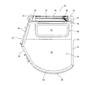
- the rear wall portion 34 is formed by arranging a rear window portion 80 and a storage portion 81 for an air conditioner capacitor in the vertical direction.
- the rear window portion 80 bulges backward between the upper end portions of the left and right rear column bodies 59 and 75 to form a curved rear upper horizontal member 82, while the left and right rear column bodies 59 and 75
- a plate-like rear middle part partition body 83 formed by bending the rear edge at the middle part in the rearward direction and being curved is horizontally mounted, and a rear view square is formed on these inner peripheral edge parts via a rear window frame body 79.
- a curved rear glass window 84 that is shaped and bulges backward in plan view is stretched and formed.
- the air-conditioner capacitor accommodating portion 81 has an inner peripheral edge formed in the shape of a horizontally long rectangular frame with the lower half of the left and right rear pillars 59, 75, the rear midway partition 83, and the rear lower horizontal plate 77.
- a box-shaped housing inner wall 85 (see FIGS. 15 to 17) is projected forward to form a recessed housing space 86 (see FIGS. 14 and 15) at the rear opening.
- the lower half of the left rear column 59 is pivotally connected to the left end edge of the opening / closing cover 88 via a pivot bracket 87 (see FIG. 15). It is said.
- the rear end edge of the opening / closing cover 88, the rear middle part partition body 83, and the rear lower horizontal plate member 77 is formed in a curved shape along the shape of the rear peripheral edge part of the revolving body 6.
- Reference numeral 89 denotes an opening / closing handle provided on the right side of the opening / closing cover 88.
- the ceiling portion 35 is formed by a front upper horizontal member 46, a front upper horizontal member 54, a rear upper horizontal member 58, a rear upper horizontal member 82, and a right upper horizontal member 74.
- a ceiling plate 90 is stretched around the periphery.
- a ceiling window 90 is formed by providing a horizontally elongated skylight glass 91 at the front portion of the ceiling plate 90.
- a left rear edge wall 100 formed by bending along the left rear edge of the revolving body 6 formed in an arc shape in plan view is erected.
- a bonnet 101 and a counterweight 102 that are curved along the upper and lower sides of the swivel body 6 are arranged up and down, and a tank unit 8 is arranged at the right rear edge of the swivel body 6.
- the cabin 30 surrounds the operating unit 7 and the functional unit 9 by the left rear edge wall 100, the bonnet 101, the counterweight 102, and the tank unit 8 on the revolving structure 6.
- Reference numeral 103 denotes a bonnet handle provided on the right side of the bonnet 101.
- the bonnet 101 can be opened to the rear left side through the bonnet handle 103.
- the operation unit 7 arranges the front wall of the seat support 111 (seat mount) 111 at the rear edge of the floor plate piece 110 that forms a part of the revolving structure 6, and supports the seat.
- a driver's seat 112 is placed in the center on the platform 111.
- a left lever support case 113 is disposed on the left side of the driver seat 112 on the seat support base 111, while a right lever support case 114 is disposed on the right side of the driver seat 112.
- a left pilot valve (not shown) is disposed in the left lever support case 113, and a left working unit operation lever 115 is projected upward from the front upper part of the left lever support case 113 and the left working unit operation lever 115. Can be tilted in the front-rear direction and the left-right direction.
- the left lever support case 113 is configured to be freely changeable between a substantially horizontal use position and a non-use position in which the left lever support case 113 is flipped up rearward and upward.
- Reference numeral 116 denotes a lock lever that protrudes forward from the front end wall of the left lever support case 113.
- a right pilot valve (not shown) is disposed in the right lever support case 114, and a right working unit operation lever 117 is projected upward from the front upper part of the right lever support case 114, and the right working unit operation lever 117. Can be tilted in the front-rear direction and the left-right direction.
- left and right traveling levers 120, 120 extending up and down through a lever hole formed in the front center portion of the floor board piece 110 are erected.
- the tilting operation is possible.
- the travel hydraulic motors of the travel units 4 and 4 are hydraulically connected to the travel levers 120 and 120 via travel control valves (not shown) so that the travel levers 120 and 120 are tilted in the front-rear direction.
- the traveling units 4 and 4 can be operated by interlocking the forward / reverse operation.
- a speed increasing pedal 121 is provided near the left side of the left travel lever 120 and provided on the floor plate piece 110, and the vehicle speed is increased by depressing the speed increasing pedal 121.
- a boom swing operation pedal 122 is provided on the floor board piece 110 so as to be positioned near the right side of the right travel lever 120.
- An operation panel 130 is formed adjacent to the right side of the right lever support case 114 so that the front and rear are long and the left and right are short.
- the operation panel unit 130 includes a rear part of the panel unit body 150 formed in a box shape that extends in the front-rear direction on a stepped convex panel support table 149 continuously provided on the right side of the seat support table 111 and opens at the lower end.
- the front part of the panel part main body 150 is connected in communication with the upper end opening of the cool / warm air discharge part 148 adjacent to the front of the panel support 149.
- a monitor 131 as a display is provided on the front upper surface of the panel body 150, and a blade lever 132 is protruded in the middle of the upper surface of the panel body 150 so as to be tiltable in the front-rear direction.
- a variety of switch groups 133 are arranged.
- the blade lever 132 is linked to a blade cylinder control valve (not shown) via a linkage mechanism 136.
- the blade cylinder control valve is hydraulically connected to the blade cylinder 28 of the soil removal unit 3.
- the earth removal part 3 can be moved up and down by interlocking the expansion and contraction operation of the blade cylinder 28 with the tilting operation of the blade lever 132 in the front-rear direction. Below, the structure of the operation panel part 130 is demonstrated concretely.
- the operation panel unit 130 is provided with a blade lever 132 as an outer operation lever on the outer side of the right working unit operation lever 117 as a working unit operation lever via the panel unit main body 150. is doing.
- the panel body 150 is formed by extending in the front-rear direction, and is provided with a through-opening portion 151 in which the blade lever 132 is disposed in the middle direction.
- a monitor 131 is provided in front of the through-hole portion 151, and various switch groups 133 and a cup holder 152 are provided behind the through-hole portion 151.
- a blade lever 132 is vertically penetrated through the through-hole portion 151 provided in the panel body 150, and the blade lever 132 is disposed outside the right working portion operation lever 117.
- the panel unit body 150 has a front portion with a front and rear sloped shape, and an inner and outer height with a sloped shape.
- the display surface of the monitor 131 provided at the front part of the panel body 150 is directed toward the viewpoint of the operator (operator) seated in the driver's seat 112.
- a cup holder 152 is provided at the rear end portion of the panel unit main body 150, and the cup holder 152 is disposed rearward from each operation range of the right working unit operation lever 117 and the blade lever 132.
- a through-hole portion 151 is provided in the middle of the panel main body 150 formed by extending in the front-rear direction so as to penetrate the blade lever 132 in the vertical direction, and the monitor is provided in front of the through-hole portion 151. While 131 is provided, various switch groups 133 and cup holders 152 are provided at the rear of the through-hole portion 151, so that the blade lever 132 and the like are integrated in a compact manner on one side of the driver's seat 112 via the panel body 150. The blade lever 132 and the like can be easily used.
- the blade lever 132 By disposing the blade lever 132 through the through-hole portion 151 of the panel body 150 in the vertical direction, the blade lever 132 can be firmly disposed on the rear outer side of the right working portion operation lever 117. It is possible to satisfactorily secure the arrangement position of 132 and the right working unit operation lever 117.
- the display surface of the monitor 131 provided at the front of the panel unit main body 150 is directed toward the viewpoint of the worker M seated on the driver's seat 112, while the cup holder 152 is placed at the rear end of the right working unit operation lever 117 and the blade lever. 132.
- the display surface of the monitor 131 can be visually recognized easily and firmly, and when the plastic bottle is stored in the cup holder 152, the plastic bottle is There is no hindrance to the operation of each lever 117,132.
- the monitor 131 is disposed on the outer front side of the right working unit operation lever 117 arranged in an upright manner, and is displayed on the display surface (monitor) on the viewpoint side of the operator M who sits on the driver's seat 112 and operates while visually checking the front.
- the upper surface portion 184) of the case 183 is directed, and the blade lever 132 is arranged upright on the rear side of the monitor 131, and the monitor 131 passes between the blade lever 132 and the right working portion operation lever 117 in the field of view of the worker M.
- the display surface is visible.
- the upper end portion of the right working unit operation lever 117, the upper end portion of the blade lever 132, and the central portion of the display surface of the monitor 131 are sequentially arranged from the driver's seat 112 to one side outside (right outside in this embodiment), The height from the floor part (floor board piece 110) of the operation part 7 is arrange
- the central portion of the display surface of the monitor 131, the upper end portion of the right working portion operation lever 117, and the upper end portion of the blade lever 132 are sequentially arranged from the front to the rear. In the field of view of the worker M, the display surface of the monitor 131 disposed on the outer lower side through the blade lever 132 and the right working unit operation lever 117 is visible.
- a display unit operation switch group 187 as a monitor operation switch is provided on the display surface of the monitor 131.
- the display unit operation switch group 187 is arranged in a range where the operator M seated in the driver's seat 112 can operate by extending his hand between the right operation unit operation lever 117 and the blade lever 132.
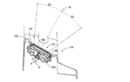
- a main display unit 185 which is a liquid crystal display having viewing angles ⁇ and ⁇ of a certain angle in the front-rear direction and the left-right direction, respectively, is used. Then, on the display surface of the liquid crystal display, the viewpoint of the worker M seated on the driver's seat 112 is always placed in the quadrangular pyramid-shaped viewing area R formed by the viewing angles ⁇ and ⁇ in the front and rear and left and right directions.
- a display surface portion 189 of a certain main display portion 185 is arranged so as to face the worker M side.
- the viewing angle ⁇ in the front-rear direction can be set to, for example, 50 degrees (25 degrees forward and 25 degrees backward) in the front-rear direction of the virtual reference line K raised from the focal point P.
- the display surface part 189 of the main display part 185 is disposed slightly forward (for example, 5 degrees) so that the operator M can easily see the display surface part 189.
- the viewing angle ⁇ in the left-right direction can be set to, for example, 50 degrees (25 degrees to the left and 25 degrees to the right) in the left-right direction of the virtual reference line K raised from the focal point P.
- the operator M is directed to the viewpoint of the worker M through the space between the blade lever 132 and the right working unit operation lever 117 in the field of view of the worker M who sits on the driver's seat 112 and operates while visually checking the front. Since the displayed display surface of the monitor 131 can be viewed, the worker M can firmly view the display surface of the monitor 131 while operating the right working unit operation lever 117 or the blade lever 132. As a result, work efficiency can be improved while ensuring safety during work.
- the display surface of the monitor 131 disposed outside and below through the blade lever 132 and the right working unit operation lever 117 is visible, so the right working unit operation lever 117 or the blade lever 132 is visible.
- the right hand r of the operator M who is operating by holding any of these levers does not hinder the visual recognition of the display surface of the monitor 131. Therefore, the display surface of the monitor 131 arranged on the outside lower side can be easily seen.
- the operator M seated in the driver's seat 112 can easily operate the display unit operation switch group 187 by reaching out between the right working unit operation lever 117 and the blade lever 132. Therefore, desired information can be quickly obtained from the monitor 131 by appropriately operating the display unit operation switch group 187. As a result, also from this point, work efficiency can be improved while ensuring safety during work.
- the display surface of the liquid crystal display that is, the display surface of the liquid crystal display, that is, the viewpoint of the worker M seated in the driver's seat 112 is always arranged in the quadrangular pyramid viewing area R formed by the viewing angles ⁇ and ⁇ in the front and rear and left and right directions. Since the display surface portion 189 of the main display portion 185 is arranged to face the worker M side, for example, when the physique of the worker M is different or when the driver's seat 112 is moved and adjusted in the front-rear direction. Even when the viewpoint position of the worker M is different, the visual field region R can always cover (cover) the viewpoint of the worker M. Therefore, even when the worker M appropriately moves and adjusts the driver's seat 112 to a desired position, the display surface portion 189 is firmly held in the field of view, and the visibility of the worker M is ensured well.
- the panel unit main body 150 is formed by connecting the main body front half rear end surface 156 of the main body front half 155 and the main body rear half front end surface 158 of the main body rear half 157 so as to be connectable and detachable in the front-rear direction.
- the front half 155 of the main body is provided with a left and right extended upper end discharge portion 160 that discharges cooling / warming air at the front portion, a front and rear extension upper end discharge portion 161 that discharges cooling / warming air is provided at the left side, and a monitor support portion 162 is provided at the right side portion.
- the monitor 131 is disposed via the monitor support portion 162.
- the upper surface of the monitor support portion 162 is a rectangular concave surface 163 that is vertically long and long, and the concave surface 163 has a front surface, a rear surface, a lower surface, and an inner surface and an outer surface. That is, the concave surface 163 is directed toward the concave surface 163 in the direction of the eyes m (see FIGS.
- a rear portion 165 is formed extending rearward from the monitor support portion 162, and an upper surface of the rear portion 165 is formed in a horizontal plane.
- a trough line 167 extending straight in the left front right rear direction is formed at the joint between the rear portion 165 whose upper surface is a horizontal surface and the concave surface 163 which is an inclined surface.
- a front half through-hole portion 166 having an upper surface and a rear end opened is formed at the center of the upper surface of the rear portion 165 of the front half portion 155 of the main body.
- the main body rear half 157 is formed by integrally forming a rear portion 165 of the main body front half 155, a front portion 170 formed with the same width on the upper surface and a rear portion 171 formed with a slightly wider upper surface left and right width than the front portion 170. Yes.
- a rear half through-hole portion 172 having an upper surface and a front end opened is formed.
- the front half through-hole portion 166 and the rear half through-hole portion 172 form a through-hole portion 151 that is joined in the front-rear direction and extends in the front-rear direction.
- a mouth cover 173 formed of an elastic material is detachably attached to the through hole 151, and the blade lever 132 is vertically penetrated through the through hole 151 via the mouth cover 173. .
- the blade lever 132 is slidable in the front-rear direction, and the through hole 151 functions as a lever guide groove.
- Various switch groups 133 are arranged on the front half side of the rear portion 171.
- the various switch groups 133 are formed by arranging volume switches 134 and push button switches 135 adjacent to each other on the left and right sides.
- a cup holder 152 that is a recess capable of accommodating a cup, a plastic bottle, or the like is disposed on the rear half of the rear portion 171.
- a left side recess 174 is formed by the left side wall of the front left side wall and the rear side 165 of the front half 155 of the main body and the left side wall of the front side 170 and the left front wall of the rear part 171 of the rear half 157 of the main body.
- the right side of the right lever support case 114 is disposed.
- the right lever support case 114 and the operation panel unit 130 are arranged in a compact manner so as to be close to each other in the left-right direction.
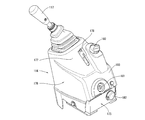
- the right lever support case 114 has a case detachable portion 176 detachably attached to a case fixing portion 175 mounted on the right side portion of the seat support base 111.
- the case detaching portion 176 connects the lower half portion formed in a rectangular cylinder shape to the case fixing portion 175, and the right working portion is operated at the upper end portion of the upper half portion formed into a quadrangular pyramid shape by being gradually reduced upward and forward.
- the lever 117 is protruded to the upper left front side.
- An armrest 179 is provided on the left side of the rear wall upper portion 177 of the case detaching portion 176, which is a forwardly inclined wall, via an armrest support 178, and an accelerator volume 180, which is a volume switch, is provided on the right side. It is protruding.
- the accelerator volume 180 is rotatable about an axis in the vertical direction and is electrically connected to a controller (not shown) that controls the rotational speed of the engine E. Then, the rotational speed of the engine E can be adjusted up or down by rotating the accelerator volume 180 forward and backward.
- a key lock portion 181 is provided on the lower portion 193 of the rear wall that has a slightly gentle slope. An engine key or the like is inserted into the key lock unit 181 so that the key lock unit 181 can be rotated. By doing so, the case detachable portion 176 can be connected to the case fixing portion 175 to be locked or unlocked, and the case detachable portion 176 is prevented from being accidentally detached.
- the case fixing portion 175 is provided with a power socket 182 (so-called cigar socket) on the right side so that electricity can be supplied from a battery (not shown) as a power source to the external electric device via the power socket 182.
- the power socket 182 can be connected to, for example, a connection terminal for a cigar lighter or pilot lamp, an adapter for a mobile phone, or the like.
- the pilot lamp mounted outside the cabin 30 is formed, for example, by forming an electric wire insertion hole (not shown) in the rear window frame 83 of the cabin 30 and inserting the electric wire through the grommet into the electric wire insertion hole. By doing so, it is possible to connect the tip connection portion of the electric wire to the power socket 182 and take out electricity from the power source. That is, a patrol lamp or the like can be appropriately connected to the power socket 182 to cause the patrol lamp or the like to function. Therefore, it is not necessary to provide an external power source for the cabin 30 even when the operation unit 7 is surrounded by the cabin 30.
- the monitor 131 is supported by a monitor support section 162 as shown in FIGS.
- the monitor 131 has a main display unit 185, a sub display unit 186, and a display unit operation switch group 187 arranged on the upper surface 184 of the monitor case 183 so as to be flush with each other in the front-rear direction.
- the monitor case 183 is formed in a vertically long flat box shape, and a stepped recess 188 is formed at the peripheral edge of the upper surface portion 184.
- the main display unit 185 is a liquid crystal display formed in a square shape in plan view, and is arranged at the center of the upper surface part 184 so that graphic information, data, and the like are displayed on the liquid crystal.
- the sub display unit 186 is an LED display unit, and is arranged in front of the upper surface unit 184 so that graphic information, data, and the like are displayed by LEDs (Light-Emitting-Diode).
- the display unit operation switch group 187 a plurality of (in this embodiment, five) switches are arranged side by side in the left-right direction immediately after the main display unit 185. And each switch 185,186 can be operated by selectively pressing each switch.
- the main display unit 185 includes a transmissive liquid crystal display body 194 that utilizes the property of whether the liquid crystal transmits or blocks light from the backlight, which is a light source, and is stretched directly above the liquid crystal display body 194.
- the display surface portion 189 is provided.
- the sub display unit 186 is configured by extending a display surface unit 191 directly above the LED 190.
- the monitor support part 162 is formed with a front and rear vertically rectangular monitor upper surface exposure port 195.
- An upper surface portion 184 of the monitor case 183 is fitted into the monitor upper surface exposure port 195 from below, and a stepped recess 188 formed on the peripheral portion of the upper surface portion 184 is engaged with the peripheral portion of the monitor upper surface exposure port 195.
- the monitor 131 is attached to the monitor support portion 162 with the upper surface portion 184 exposed from the monitor upper surface exposure port 195.
- the upper surface portion 184 of the monitor case 183 that is the display surface of the monitor 131 can be visually recognized through the space between the blade lever 132 and the right working portion operation lever 117 within the field of view of the worker M.
- the visual field region R of the display surface portion 189 of the main display portion 185 having the viewing angles ⁇ and ⁇ is a one-point perspective view from the focal point P to the worker M side through the periphery of the display surface portion 189. It is enlarged and formed into a quadrangular pyramid shape.
- the viewpoint of the worker M seated on the driver's seat 112 is always arranged in the visual field region R of the display surface portion 189 of the main display unit 185. Even when the position is appropriately adjusted to the desired position, the display surface portion 189 is firmly held within the field of view, and the visibility of the worker M to the display surface portion 189 is ensured.
- the sub display unit 186 is disposed on the front side of the main display unit 185, which is a side away from the blade lever 132 and the right working unit operation lever 117. Therefore, the viewpoint of the worker M seated on the driver's seat 112 is always arranged in the visual field area of the display surface portion 189 of the main display portion 185 and the display surface portion 191 of the sub display portion 186, which are the display surfaces of the monitor 131. As a result, even when the operator M appropriately moves and adjusts the driver's seat 112 to a desired position, both display surface portions 189 and 191 are firmly held within the field of view, and the operator M can visually recognize the display surface of the monitor 131. Good quality is ensured.
- the functional unit 9 has an engine room 139 below the seat support base 111, and an engine E as a prime mover unit and a support body 141 are disposed in the engine room 139. is doing.
- the engine E is disposed with its axis line directed in the left-right direction.
- a support portion 141 is integrally formed at the rear portion of the seat support base 111 and is disposed above the rear portion of the engine E so that the rear portion of the cabin 30 is supported by the upper end portion of the support portion 141.
- the tank portion 8 is provided with a fuel tank for storing fuel for driving the engine E and a hydraulic oil tank for storing hydraulic oil (these are not shown) adjacent to each other in the front-rear direction. is doing.
- These tanks include a front tank cover body 142 that is bent and formed on the right front portion of the swivel body 6 and a first tank disposed along the front side edge of the swivel body 6.
- Second tank cover bodies 143 and 144 see FIGS.
- an inner wall body (not shown) erected on the right inner side of the floor plate piece 110, the front tank cover body 142, the first and first tank covers Two tank cover bodies 143 and 144 and an upper surface cover body 145 (see FIGS. 2 and 4) disposed on the upper edge of the inner wall body are closed.
- the upper cover body 145 allows the upper part of both tanks to be opened and closed.
- the air conditioner capacitor accommodating portion 81 includes an air conditioner capacitor 200 that cools and liquefies the compressed high-temperature and high-pressure refrigerant in the accommodating space 86, and the air conditioner capacitor 200.
- a receiver dryer 201 that temporarily stores the liquefied refrigerant and a washer tank 202 are provided.
- the receiver dryer 201 contains therein a strainer that removes impurities from the refrigerant and a desiccant that removes moisture.
- 203 is a wind guide
- 204 is a fan.
- FIG. 23 to 25 show an operation panel unit 130 according to another embodiment.
- the operation panel unit 130 has the same basic structure as the operation panel unit 130 of the above embodiment, but is not provided with a left / right extended upper end discharge portion 160 and a front / rear extended upper end discharge portion 161 in the front half 155 of the main body. The difference is that an accessory case 210 is provided in the rear half 157 of the main body instead of the volume switch 134.
- monitor support portion 162 is provided in the front half 155 of the main body, and the monitor 131 is disposed via the monitor support portion 162.
- a power supply socket provided on the right side of the case fixing portion 175 of the right lever support case 114 is provided with an accessory case 210 on the left side in the front half of the rear portion 171 of the main body rear portion 157 instead of the volume type switch 134. 182 and the accessory case 210 are arranged close to each other.
- Reference numeral 211 denotes a lower cover that covers the lower part of the front half 155 of the panel body 150.
- the power socket 182 provided on the right side of the case fixing portion 175 of the right lever support case 114 and the accessory case 210 provided on the panel body 150 are disposed close to each other.
- the mobile phone can be charged during work by connecting the mobile phone housed in the accessory box and the power socket 182 via the adapter.
Landscapes
- Engineering & Computer Science (AREA)
- Mining & Mineral Resources (AREA)
- Civil Engineering (AREA)
- General Engineering & Computer Science (AREA)
- Structural Engineering (AREA)
- Mechanical Engineering (AREA)
- Fittings On The Vehicle Exterior For Carrying Loads, And Devices For Holding Or Mounting Articles (AREA)
- Component Parts Of Construction Machinery (AREA)
Description
掘削作業車Aは、図1~図7に示すように、自走可能な走行機体1と、走行機体1に取り付けた作業部としての掘削部2と排土部3とから構成している。本実施形態では作業部の先端部に作業用アタッチメントとして掘削用のバケット13を装着して掘削部2となしている。
キャビン30は前記したように旋回体6上に載設して、タンク部8を除く運転部7と機能部9を囲繞している。すなわち、キャビン30は、図8~図13に示すように、前壁部31と左側壁部32と右側壁部33と後壁部34と天井部35とから下面開口の箱形に形成している。
運転部7は、図14~図17に示すように、旋回体6の一部を形成する床板片110の後端縁部に座席支持台(シートマウント)111の前壁を配置し、座席支持台111上の中央部に運転席112を載設している。座席支持台111上の運転席112の左側には左レバー支持ケース113を配設する一方、運転席112の右側には右レバー支持ケース114を配設している。左レバー支持ケース113内には左パイロット弁(図示せず)を配設し、左レバー支持ケース113の前上部から左作業部操作レバー115を上方へ突設するとともに、左作業部操作レバー115を前後方向と左右方向に傾倒操作可能としている。
操作パネル部130は、図16及び図17に示すように、作業部操作レバーとしての右作業部操作レバー117の外側方にパネル部本体150を介して外側操作レバーとしてのブレードレバー132を配設している。パネル部本体150は前後方向に伸延させて形成して、中途部にブレードレバー132を上下方向に貫通させて配置する貫通口部151を設けている。貫通口部151の前方にはモニター131を設ける一方、貫通口部151の後方に各種スイッチ群133とカップホルダー152を設けている。パネル部本体150に設けた貫通口部151にはブレードレバー132を上下方向に貫通させて配置するとともに、ブレードレバー132は右作業部操作レバー117の後外側に配置している。
次に、モニター131の構成を図17,図19~図22を参照しながら説明する。すなわち、モニター131は、起立状に配置した右作業部操作レバー117の外側前方に配置するとともに、運転席112に着座して前方を視認しながら操作する作業者Mの視点側に表示面(モニターケース183の上面部184)を指向させ、モニター131の後方にはブレードレバー132を起立状に配置して、作業者Mの視野内でブレードレバー132と右作業部操作レバー117の間を通してモニター131の表示面を視認可能となしている。
機能部9は、図14及び図15に示すように、座席支持台111の下方をエンジンルーム139となして、エンジンルーム139内に原動機部としてのエンジンE等と支持体部141とを配設している。エンジンEは左右方向に軸線を向けて配置している。座席支持台111の後部には支持体部141を一体成形するとともに、エンジンEの後部上方に配置して、支持体部141の上端部によりキャビン30の後部を支持している。
タンク部8は、図14に示すように、エンジンEを駆動するための燃料を収容する燃料タンクと、作動油を収容する作動油タンク(これらは図示せず)を前後に隣接させて配設している。これらのタンクは、旋回体6の右側前部上に湾曲状に屈曲形成して立設した前タンクカバー体142と、旋回体6の前部側縁部に沿わせて配設した第1・第2タンクカバー体143,144(図2及び図4参照)と、床板片110の右側内方に立設した内壁体(図示せず)と、これらの前タンクカバー体142と第1・第2タンクカバー体143,144と内壁体の上端縁部上に配設した上面カバー体145(図2及び図4参照)とにより閉塞している。そして、上面カバー体145により両タンクの上方を開閉自在となしている。
エアコン用コンデンサ等収容部81は、図14及び図15に示すように、収容空間86内に、圧縮されて高温高圧になった冷媒を冷やして液化するエアコン用コンデンサ200と、エアコン用コンデンサ200によって液化された冷媒を一時的に蓄えておくレシーバードライヤ201と、ウオッシャータンク202を配設している。レシーバードライヤ201は内部に冷媒の不純物を取り除くストレーナと水分を除去する乾燥剤を収容している。203は導風体、204はファンである。
図23~図25は、他の実施形態に係る操作パネル部130を示している。かかる操作パネル部130は、前記実施形態の操作パネル部130と基本的な構造を同じくしているが、本体前半部155に左右伸延上端放出部160と前後伸延上端放出部161を設けていない点と、本体後半部157にボリューム式のスイッチ134に代えて小物入れ210を設けている点で異なる。
1 走行機体
2 掘削部
3 排土部
4 走行部
117 右作業部操作レバー
131 モニター
132 ブレードレバー
151 貫通口部
189 液晶表示面
R 視野領域
Ls 視線
Q1 レバー近傍視野面
Q2 視点近傍視野面
Claims (4)
- 旋回体上に配設した運転部に運転席を配置し、運転席の左右いずれか一側方に作業部を操作する作業部操作レバーと、各種情報を表示するモニターを配設した旋回作業車のモニター配設構造であって、
モニターは、起立状に配置した作業部操作レバーの外側前方に配置するとともに、運転席に着座して前方を視認しながら操作する作業者の視点側に表示面を指向させ、
モニターの後方には外側操作レバーを起立状に配置して、作業者の視野内で外側操作レバーと作業部操作レバーの間を通してモニターの表示面を視認可能となしたことを特徴とする旋回作業車。 - 作業部操作レバーの上端部と外側操作レバーの上端部とモニターの表示面の中央部を順次、運転席から一側外方へ配置するとともに、運転部の床部からの高さを低位置に配置し、モニターの表示面の中央部と作業部操作レバーの上端部と外側操作レバーの上端部を順次前方から後方へ配置して、作業者の視野内で外側操作レバーと作業部操作レバーの間を通して外側下方に配置されたモニターの表示面を視認可能となしたことを特徴とする請求項1記載の旋回作業車。
- モニターの表示面近傍にはモニター操作スイッチを設けるとともに、モニター操作スイッチは運転席に着座した作業者が作業部操作レバーと外側操作レバーの間に手を伸ばして操作可能としたことを特徴とする請求項1又は2記載の旋回作業車。
- モニターとしては前後方向と左右方向にそれぞれ一定角度の視野角を有する液晶表示器を使用し、前後・左右方向の視野角で形成される四角錘状の視野領域内に運転席に着座した作業者の視点が常時配置されるように液晶表示器の表示面を作業者側に指向させて配置したことを特徴とする請求項1~3のいずれか1項記載の旋回作業車。
Priority Applications (5)
| Application Number | Priority Date | Filing Date | Title |
|---|---|---|---|
| EP13796633.9A EP2857596B1 (en) | 2012-05-28 | 2013-02-19 | Swiveling work vehicle with operator display means |
| US14/403,956 US9518375B2 (en) | 2012-05-28 | 2013-02-19 | Turning working vehicle |
| AU2013268936A AU2013268936B2 (en) | 2012-05-28 | 2013-02-19 | Swiveling work vehicle |
| KR1020147031218A KR101943147B1 (ko) | 2012-05-28 | 2013-02-19 | 선회 작업차 |
| CN201380028195.4A CN104350212B (zh) | 2012-05-28 | 2013-02-19 | 旋回作业车 |
Applications Claiming Priority (2)
| Application Number | Priority Date | Filing Date | Title |
|---|---|---|---|
| JP2012-121228 | 2012-05-28 | ||
| JP2012121228A JP5841008B2 (ja) | 2012-05-28 | 2012-05-28 | 旋回作業車 |
Publications (1)
| Publication Number | Publication Date |
|---|---|
| WO2013179695A1 true WO2013179695A1 (ja) | 2013-12-05 |
Family
ID=49672911
Family Applications (1)
| Application Number | Title | Priority Date | Filing Date |
|---|---|---|---|
| PCT/JP2013/053947 Ceased WO2013179695A1 (ja) | 2012-05-28 | 2013-02-19 | 旋回作業車 |
Country Status (7)
| Country | Link |
|---|---|
| US (1) | US9518375B2 (ja) |
| EP (1) | EP2857596B1 (ja) |
| JP (1) | JP5841008B2 (ja) |
| KR (1) | KR101943147B1 (ja) |
| CN (1) | CN104350212B (ja) |
| AU (1) | AU2013268936B2 (ja) |
| WO (1) | WO2013179695A1 (ja) |
Families Citing this family (16)
| Publication number | Priority date | Publication date | Assignee | Title |
|---|---|---|---|---|
| DE112014000164A5 (de) * | 2014-10-23 | 2015-07-02 | Komatsu Ltd. | Steueranordnung und Baumaschinen-Kabine |
| GB2531762A (en) * | 2014-10-29 | 2016-05-04 | Bamford Excavators Ltd | Working machine |
| EP3279401B1 (en) * | 2015-03-30 | 2023-05-31 | Kubota Corporation | Work machine |
| JP6813268B2 (ja) * | 2016-02-16 | 2021-01-13 | 株式会社小松製作所 | 作業車両 |
| US9745719B1 (en) * | 2016-02-29 | 2017-08-29 | Deere & Company | Mechanical control arrangement for work vehicle |
| US10434914B2 (en) * | 2017-03-13 | 2019-10-08 | Cnh Industrial America Llc | Armrest system for holding monitors in an operator cab |
| JP6646607B2 (ja) * | 2017-03-28 | 2020-02-14 | 日立建機株式会社 | 転圧機械 |
| JP6971773B2 (ja) | 2017-10-20 | 2021-11-24 | 株式会社小松製作所 | 作業車両のキャブ、作業車両およびホイールローダ |
| JP6827916B2 (ja) * | 2017-12-27 | 2021-02-10 | 株式会社クボタ | レバー装置及びそれを備えた作業機 |
| CA3106884C (en) | 2018-07-19 | 2025-04-01 | Doosan Bobcat North America, Inc. | DISPLAY POSITION FOR CABIN WITH TILTING DOOR |
| JP7117238B2 (ja) * | 2018-12-27 | 2022-08-12 | 日立建機株式会社 | 作業車両 |
| JP7012038B2 (ja) * | 2019-03-08 | 2022-01-27 | 日立建機株式会社 | 作業機械 |
| JP7473305B2 (ja) * | 2019-07-10 | 2024-04-23 | 株式会社小松製作所 | キャブおよび作業車両 |
| JP7567623B2 (ja) * | 2021-03-29 | 2024-10-16 | コベルコ建機株式会社 | 作業機械のキャブ |
| WO2023276374A1 (ja) * | 2021-06-30 | 2023-01-05 | 株式会社クボタ | 作業機 |
| JP2025142989A (ja) * | 2024-03-18 | 2025-10-01 | ヤンマーホールディングス株式会社 | 作業機械 |
Citations (4)
| Publication number | Priority date | Publication date | Assignee | Title |
|---|---|---|---|---|
| JPH0297445U (ja) * | 1989-01-13 | 1990-08-02 | ||
| JP2002061222A (ja) * | 2000-08-24 | 2002-02-28 | Hitachi Constr Mach Co Ltd | 旋回式建設機械 |
| JP2003184131A (ja) | 2001-12-19 | 2003-07-03 | Hitachi Constr Mach Co Ltd | 建設機械の操作装置 |
| JP2009236617A (ja) * | 2008-03-26 | 2009-10-15 | Kubota Corp | 作業機の表示装置 |
Family Cites Families (16)
| Publication number | Priority date | Publication date | Assignee | Title |
|---|---|---|---|---|
| US4733745A (en) * | 1986-05-14 | 1988-03-29 | Machinery Distribution, Inc. | Adjustable control attachment for an earth moving vehicle |
| US5924515A (en) | 1997-03-17 | 1999-07-20 | New Holland North America, Inc. | Operator seat sliding control console |
| JP2004249843A (ja) | 2003-02-20 | 2004-09-09 | Komatsu Ltd | 作業機械における移動式運転室の通路遮断装置 |
| JP2005068892A (ja) * | 2003-08-27 | 2005-03-17 | Sumitomo (Shi) Construction Machinery Manufacturing Co Ltd | 建設機械の操作パネル |
| JP4629377B2 (ja) * | 2003-09-02 | 2011-02-09 | 株式会社小松製作所 | 建設機械 |
| JP2005163370A (ja) | 2003-12-02 | 2005-06-23 | Hitachi Constr Mach Co Ltd | 建設機械の画像表示装置 |
| JP5031978B2 (ja) * | 2004-07-05 | 2012-09-26 | 日立建機株式会社 | 建設機械の表示装置 |
| JP4252526B2 (ja) * | 2004-11-30 | 2009-04-08 | 住友建機製造株式会社 | 建設機械のスロットルボリューム装置 |
| JP4694893B2 (ja) | 2005-06-02 | 2011-06-08 | 日立建機株式会社 | 建設機械 |
| CN201033877Y (zh) * | 2007-05-29 | 2008-03-12 | 徐州徐挖机械制造有限公司 | 挖掘机驾驶室 |
| JP5095754B2 (ja) | 2007-12-13 | 2012-12-12 | 株式会社小松製作所 | リッパの操作装置 |
| JP4740973B2 (ja) | 2008-03-26 | 2011-08-03 | 株式会社クボタ | 作業機の表示装置 |
| KR101090619B1 (ko) | 2008-03-26 | 2011-12-08 | 가부시끼 가이샤 구보다 | 작업기의 표시 장치 |
| JP5174742B2 (ja) | 2009-05-19 | 2013-04-03 | 日立建機株式会社 | 建設機械の給脂装置 |
| CN201485892U (zh) * | 2009-08-28 | 2010-05-26 | 中钢集团衡阳重机有限公司 | 挖掘机整体式操作台 |
| JP2012188899A (ja) * | 2011-03-14 | 2012-10-04 | Kobelco Contstruction Machinery Ltd | 建設機械 |
-
2012
- 2012-05-28 JP JP2012121228A patent/JP5841008B2/ja active Active
-
2013
- 2013-02-19 WO PCT/JP2013/053947 patent/WO2013179695A1/ja not_active Ceased
- 2013-02-19 EP EP13796633.9A patent/EP2857596B1/en active Active
- 2013-02-19 US US14/403,956 patent/US9518375B2/en active Active
- 2013-02-19 KR KR1020147031218A patent/KR101943147B1/ko active Active
- 2013-02-19 AU AU2013268936A patent/AU2013268936B2/en not_active Ceased
- 2013-02-19 CN CN201380028195.4A patent/CN104350212B/zh active Active
Patent Citations (4)
| Publication number | Priority date | Publication date | Assignee | Title |
|---|---|---|---|---|
| JPH0297445U (ja) * | 1989-01-13 | 1990-08-02 | ||
| JP2002061222A (ja) * | 2000-08-24 | 2002-02-28 | Hitachi Constr Mach Co Ltd | 旋回式建設機械 |
| JP2003184131A (ja) | 2001-12-19 | 2003-07-03 | Hitachi Constr Mach Co Ltd | 建設機械の操作装置 |
| JP2009236617A (ja) * | 2008-03-26 | 2009-10-15 | Kubota Corp | 作業機の表示装置 |
Also Published As
| Publication number | Publication date |
|---|---|
| US9518375B2 (en) | 2016-12-13 |
| AU2013268936B2 (en) | 2016-05-12 |
| US20150130219A1 (en) | 2015-05-14 |
| JP2013245509A (ja) | 2013-12-09 |
| CN104350212B (zh) | 2016-08-31 |
| EP2857596B1 (en) | 2018-06-06 |
| EP2857596A1 (en) | 2015-04-08 |
| KR101943147B1 (ko) | 2019-01-28 |
| AU2013268936A1 (en) | 2014-12-18 |
| EP2857596A4 (en) | 2016-06-15 |
| CN104350212A (zh) | 2015-02-11 |
| KR20150027047A (ko) | 2015-03-11 |
| JP5841008B2 (ja) | 2016-01-06 |
Similar Documents
| Publication | Publication Date | Title |
|---|---|---|
| JP5841008B2 (ja) | 旋回作業車 | |
| JP5992727B2 (ja) | 旋回作業車 | |
| KR100496915B1 (ko) | 건설기계용 캐브 | |
| KR101974962B1 (ko) | 소형의 유압 셔블 | |
| WO2013179694A1 (ja) | 旋回作業車 | |
| JP5536964B1 (ja) | 建設機械用キャブおよび建設機械 | |
| WO2005075753A1 (ja) | 建設機械 | |
| JP7592785B2 (ja) | キャブおよび作業車両 | |
| JP5635875B2 (ja) | コンバイン | |
| US20090230710A1 (en) | Rear accessible service hatch | |
| JP7337685B2 (ja) | 印刷物を収容する収容体を備える作業機 | |
| JP2005112049A (ja) | エンジンルームのカバー装置 | |
| JP2001262626A (ja) | 建設機械 | |
| JP5781973B2 (ja) | 作業車 | |
| JP2006335201A (ja) | 作業車両 | |
| JP2023067286A (ja) | ショベル | |
| JP2020111077A (ja) | 車両用表示装置 | |
| JP2013245507A (ja) | 旋回作業車 | |
| JP2013245506A (ja) | 旋回作業車 |
Legal Events
| Date | Code | Title | Description |
|---|---|---|---|
| 121 | Ep: the epo has been informed by wipo that ep was designated in this application |
Ref document number: 13796633 Country of ref document: EP Kind code of ref document: A1 |
|
| ENP | Entry into the national phase |
Ref document number: 20147031218 Country of ref document: KR Kind code of ref document: A |
|
| WWE | Wipo information: entry into national phase |
Ref document number: 14403956 Country of ref document: US |
|
| NENP | Non-entry into the national phase |
Ref country code: DE |
|
| WWE | Wipo information: entry into national phase |
Ref document number: 2013796633 Country of ref document: EP |
|
| ENP | Entry into the national phase |
Ref document number: 2013268936 Country of ref document: AU Date of ref document: 20130219 Kind code of ref document: A |