WO2013179964A1 - 滅菌処理装置およびそれを用いた滅菌処理方法 - Google Patents
滅菌処理装置およびそれを用いた滅菌処理方法 Download PDFInfo
- Publication number
- WO2013179964A1 WO2013179964A1 PCT/JP2013/064188 JP2013064188W WO2013179964A1 WO 2013179964 A1 WO2013179964 A1 WO 2013179964A1 JP 2013064188 W JP2013064188 W JP 2013064188W WO 2013179964 A1 WO2013179964 A1 WO 2013179964A1
- Authority
- WO
- WIPO (PCT)
- Prior art keywords
- sterilization
- reaction container
- plasma
- reaction vessel
- agent
- Prior art date
- Legal status (The legal status is an assumption and is not a legal conclusion. Google has not performed a legal analysis and makes no representation as to the accuracy of the status listed.)
- Ceased
Links
Images


Classifications
-
- A—HUMAN NECESSITIES
- A61—MEDICAL OR VETERINARY SCIENCE; HYGIENE
- A61L—METHODS OR APPARATUS FOR STERILISING MATERIALS OR OBJECTS IN GENERAL; DISINFECTION, STERILISATION OR DEODORISATION OF AIR; CHEMICAL ASPECTS OF BANDAGES, DRESSINGS, ABSORBENT PADS OR SURGICAL ARTICLES; MATERIALS FOR BANDAGES, DRESSINGS, ABSORBENT PADS OR SURGICAL ARTICLES
- A61L2/00—Disinfection or sterilisation of materials or objects, in general; Accessories therefor
- A61L2/16—Disinfection or sterilisation of materials or objects, in general; Accessories therefor using chemical substances
- A61L2/18—Liquid substances
- A61L2/186—Peroxide solutions
-
- A—HUMAN NECESSITIES
- A61—MEDICAL OR VETERINARY SCIENCE; HYGIENE
- A61L—METHODS OR APPARATUS FOR STERILISING MATERIALS OR OBJECTS IN GENERAL; DISINFECTION, STERILISATION OR DEODORISATION OF AIR; CHEMICAL ASPECTS OF BANDAGES, DRESSINGS, ABSORBENT PADS OR SURGICAL ARTICLES; MATERIALS FOR BANDAGES, DRESSINGS, ABSORBENT PADS OR SURGICAL ARTICLES
- A61L2/00—Disinfection or sterilisation of materials or objects, in general; Accessories therefor
- A61L2/02—Disinfection or sterilisation of materials or objects, in general; Accessories therefor using physical processes
- A61L2/14—Plasma, i.e. ionised gases
-
- A—HUMAN NECESSITIES
- A61—MEDICAL OR VETERINARY SCIENCE; HYGIENE
- A61L—METHODS OR APPARATUS FOR STERILISING MATERIALS OR OBJECTS IN GENERAL; DISINFECTION, STERILISATION OR DEODORISATION OF AIR; CHEMICAL ASPECTS OF BANDAGES, DRESSINGS, ABSORBENT PADS OR SURGICAL ARTICLES; MATERIALS FOR BANDAGES, DRESSINGS, ABSORBENT PADS OR SURGICAL ARTICLES
- A61L2/00—Disinfection or sterilisation of materials or objects, in general; Accessories therefor
- A61L2/16—Disinfection or sterilisation of materials or objects, in general; Accessories therefor using chemical substances
- A61L2/18—Liquid substances
-
- B—PERFORMING OPERATIONS; TRANSPORTING
- B01—PHYSICAL OR CHEMICAL PROCESSES OR APPARATUS IN GENERAL
- B01J—CHEMICAL OR PHYSICAL PROCESSES, e.g. CATALYSIS OR COLLOID CHEMISTRY; THEIR RELEVANT APPARATUS
- B01J19/00—Chemical, physical or physico-chemical processes in general; Their relevant apparatus
- B01J19/08—Processes employing the direct application of electric or wave energy, or particle radiation; Apparatus therefor
- B01J19/087—Processes employing the direct application of electric or wave energy, or particle radiation; Apparatus therefor employing electric or magnetic energy
- B01J19/088—Processes employing the direct application of electric or wave energy, or particle radiation; Apparatus therefor employing electric or magnetic energy giving rise to electric discharges
-
- H—ELECTRICITY
- H05—ELECTRIC TECHNIQUES NOT OTHERWISE PROVIDED FOR
- H05H—PLASMA TECHNIQUE; PRODUCTION OF ACCELERATED ELECTRICALLY-CHARGED PARTICLES OR OF NEUTRONS; PRODUCTION OR ACCELERATION OF NEUTRAL MOLECULAR OR ATOMIC BEAMS
- H05H1/00—Generating plasma; Handling plasma
- H05H1/24—Generating plasma
- H05H1/46—Generating plasma using applied electromagnetic fields, e.g. high frequency or microwave energy
- H05H1/4645—Radiofrequency discharges
- H05H1/466—Radiofrequency discharges using capacitive coupling means, e.g. electrodes
-
- A—HUMAN NECESSITIES
- A61—MEDICAL OR VETERINARY SCIENCE; HYGIENE
- A61L—METHODS OR APPARATUS FOR STERILISING MATERIALS OR OBJECTS IN GENERAL; DISINFECTION, STERILISATION OR DEODORISATION OF AIR; CHEMICAL ASPECTS OF BANDAGES, DRESSINGS, ABSORBENT PADS OR SURGICAL ARTICLES; MATERIALS FOR BANDAGES, DRESSINGS, ABSORBENT PADS OR SURGICAL ARTICLES
- A61L2103/00—Materials or objects being the target of disinfection or sterilisation
- A61L2103/15—Laboratory, medical or dentistry appliances, e.g. catheters or sharps
-
- H—ELECTRICITY
- H05—ELECTRIC TECHNIQUES NOT OTHERWISE PROVIDED FOR
- H05H—PLASMA TECHNIQUE; PRODUCTION OF ACCELERATED ELECTRICALLY-CHARGED PARTICLES OR OF NEUTRONS; PRODUCTION OR ACCELERATION OF NEUTRAL MOLECULAR OR ATOMIC BEAMS
- H05H1/00—Generating plasma; Handling plasma
- H05H1/24—Generating plasma
- H05H1/46—Generating plasma using applied electromagnetic fields, e.g. high frequency or microwave energy
- H05H1/4645—Radiofrequency discharges
-
- H—ELECTRICITY
- H05—ELECTRIC TECHNIQUES NOT OTHERWISE PROVIDED FOR
- H05H—PLASMA TECHNIQUE; PRODUCTION OF ACCELERATED ELECTRICALLY-CHARGED PARTICLES OR OF NEUTRONS; PRODUCTION OR ACCELERATION OF NEUTRAL MOLECULAR OR ATOMIC BEAMS
- H05H2245/00—Applications of plasma devices
- H05H2245/30—Medical applications
- H05H2245/36—Sterilisation of objects, liquids, volumes or surfaces
Definitions
- the present invention relates to a sterilization apparatus and a sterilization method using the same, more specifically, a sterilization apparatus that performs sterilization using a peracid agent containing at least peracetic acid as a drug, and a sterilization method using the same. Is.
- the object to be sterilized is placed in a reaction container, and the inside of the reaction container is evacuated to inject a sterilization drug, and the drug vaporizes and expands to become thin.
- a sterilization method that satisfies the above requirements, the object to be sterilized is placed in a reaction container, and the inside of the reaction container is evacuated to inject a sterilization drug, and the drug vaporizes and expands to become thin.
- sterilization can be performed to every corner of a thin hollow tube by reaching the inside of the hollow tube without depending on a high temperature.
- Patent Document 1 and Patent Document 2 a sterilization process intended to obtain a higher sterilization effect by applying plasma to a process for performing a sterilization process by vaporizing a drug in a vacuum as described above. A method has been proposed.
- a peracid agent containing at least peracetic acid as a sterilization treatment agent, a higher sterilization effect can be obtained with a relatively small amount. It exists as an equilibrium mixture of peracetic acid and acetic acid, hydrogen peroxide and water, and has a very strong irritating odor. Therefore, when performing the sterilization treatment, it is necessary to suppress the influence of the pungent odor on the work environment as much as possible. In this case, it is practically required to suppress the adverse effects of the irritating odor with a relatively simple configuration without providing a large-scale and high-cost deodorizing apparatus.
- the present invention has been made in view of such a technical problem.
- the present invention In sterilization using a peracid agent containing at least peracetic acid as a drug, the present invention has a relatively simple configuration, and does not cause bromination of the drug remaining after the sterilization process.
- the basic objective is to be able to
- the inventor of the present application is proceeding with various research and development to achieve such an object, and after the sterilization treatment, the peracid agent containing peracetic acid is decomposed by irradiating the drug with plasma. It has been found that by maintaining the plasma generation state during the decompression process in the fluid path leading to the outside, the drug remaining in the container after sterilization can be effectively non-brominated.
- the sterilization apparatus includes: a) a reaction container that accommodates an object to be sterilized and performs sterilization; and b) a peracid containing at least peracetic acid in the reaction container as a sterilization drug.
- a medicine supply means to supply c) a decompression means for decompressing the inside of the reaction container; d) a ventilation means for ventilating the inside of the reaction container; e) a storage position of the sterilization target in the reaction container; Plasma generating means for generating plasma at a predetermined location in the fluid path from the vicinity to the outside of the apparatus; and f) maintaining the predetermined location in the plasma generation state in the process of depressurizing the inside of the reaction container after the sterilization treatment with the chemical.
- the apparatus includes a control unit that controls the decompression unit and the plasma generation unit.
- a second supply means for supplying a peracid decomposing agent or water that promotes decomposition of the peracid agent into the reaction container; You may make it provide further.
- the predetermined portion of the fluid path may be set in the reaction vessel or may be set outside the reaction vessel. Furthermore, it may be set both inside and outside the reaction vessel.
- the sterilization method includes: a) a processing object storage step for storing a sterilization target object in a predetermined storage position in the reaction container for sterilization; and b) after depressurizing the inside of the reaction container.
- a plasma generation step for generating plasma at a predetermined location in a fluid path from the vicinity to the outside of the apparatus, and d) re-reducing the pressure in the reaction vessel again while the predetermined location is maintained in the plasma generation state.
- a step of supplying a peracid decomposing agent or water for promoting the decomposition of the peracid agent into the reaction container is further provided. May be.
- a peracid agent containing at least peracetic acid is used as a sterilization treatment agent, and the sterilization target object is accommodated in the reaction vessel in the process of reducing the pressure in the reaction vessel after the sterilization treatment with the agent. Since the predetermined location of the fluid path from the position and the vicinity thereof to the outside of the apparatus is maintained in the plasma generation state, the drug remaining in the container after the sterilization process can be effectively non-brominated, and when performing the sterilization process, The effect of the pungent odor of the drug on the work environment can be effectively suppressed. In this case, with a relatively simple configuration in which only the plasma generation site and the decompression timing are devised, it is possible to reduce the adverse effects caused by the irritating odor of the medicine without providing a large-scale and high-cost deodorizing device.
- FIG. 1 is a configuration diagram schematically showing the overall configuration of the sterilization apparatus according to the first embodiment of the present invention.
- a sterilization apparatus M1 according to this embodiment includes a reaction container 1 that contains a sterilization target object Jb and performs a sterilization process, and a peracid containing at least peracetic acid in the reaction container 1.
- a vacuum pump 3 constituting the main part of the decompression means for decompressing the reaction container 1 and the ventilation means for ventilating the reaction container 1, and the sterilization target Jb.
- a high-frequency power supply device 4 is provided as plasma generating means for generating plasma at a predetermined position in a fluid path from the housing position in the reaction vessel 1 and the vicinity thereof to the outside of the device M1.
- the reaction container 1 is composed of an outer box 1a that covers the inside of the container 1 in an airtight manner, and an inner box 1b that is disposed inside the outer box 1a.
- Both the outer box 1a and the inner box 1b are formed of a conductive material having predetermined strength, rigidity, and corrosion resistance, and the both 1a and 1b are electrically insulated.
- a material material for forming the outer box 1a and the inner box 1b for example, a metal plate such as a steel plate can be used.
- the outer box 1a is formed by bending an ordinary flat plate-like metal plate. The inside is covered airtight with respect to the outside.
- the inner box 1b is formed by bending a perforated metal plate having a large number of through holes. Between the inner side and the outer side, gas or plasma such as vaporized medicine or air, plasma, liquid, etc. The fluid can be freely distributed.
- the processing object Jb that is an endoscope is held inside the inner box 1b having a large number of through holes.
- the processing object Jb may be directly supported by the inner surface of the inner box 1b, or a dedicated mounting table (not shown) or the like is arranged in the inner box 1b so as to be supported thereon. Also good.
- the chemical injection device 2 is connected to one side (upstream side) of the reaction vessel 1 via an injection pipe 2p provided with an open / close control valve 2b.
- the drug injection device 2 is for injecting a peracid agent containing at least peracetic acid into the reaction container 1 as a sterilization agent.
- the vacuum pump 3 is connected to the other side (downstream side) of the reaction vessel 1 via a connection pipe 3p provided with an open / close control valve 3b.
- a connection pipe 3p provided with an open / close control valve 3b.
- the inside of the reaction vessel 1 can be depressurized to an arbitrary pressure.
- an exhaust pipe 3d Connected to the downstream side of the vacuum pump 3 is an exhaust pipe 3d that exhausts the gas sucked from the inside of the container 1 toward the outside of the sterilization apparatus M1.
- one side (upstream side) of the reaction container 1 is connected to the side of the drug injection device 2 with an outside air introduction pipe 6p provided with an opening / closing control valve 6b.
- the outside air introduction pipe 6p opens the open / close control valve 6b when the inside of the reaction vessel 1 is depressurized after the sterilization treatment with the medicine, and after the depressurization step, the reaction vessel 1 is ventilated to replace air. In this way, the outside air is introduced into the reaction vessel 1.
- the outside air introduction pipe 6p, the open / close control valve 6b, the connection pipe 3p, the open / close control valve 3b, the vacuum pump 3 and the exhaust pipe 3d constitute a ventilation means for ventilating the inside of the reaction vessel 1 after one cycle relating to sterilization is completed. Has been.
- the pump 3 and the exhaust pipe 3d constitute a fluid path from the accommodation position of the processing object Jb in the reaction vessel 1 and the vicinity thereof to the outside of the apparatus M1.
- the path serves as an exhaust path.
- a high frequency power supply device 4 as plasma generating means is provided outside the reaction vessel 1 in order to generate plasma at a predetermined location in the fluid path.
- the high-frequency power supply device 4 is configured by interposing a high-frequency power source 4 s with a high-frequency circuit 4 c, one end side of the high-frequency circuit 4 c is electrically connected to the outer box 1 a of the reaction vessel 1, and the other end side is a vacuum sleeve. 5 is electrically connected to the inner box 1 b of the reaction vessel 1. And it is comprised so that a plasma can be generated in the space part formed between the outer case 1a and the inner case 1b by operating the high frequency power supply 4s.
- the vacuum sleeve 5 has the same configuration and operation as those conventionally known.
- the outer sleeve Although it is necessary to connect the lead wire on the other end side of the circuit 4c to the inner box 1b through the la, the vacuum sleeve 5 hermetically seals this penetrating portion and maintains the vacuum inside the container 1, It is comprised so that the conducting wire of the other end side of the circuit 4c can be penetrated.
- the sterilization apparatus M1 is provided with a controller EC1, which includes a microcomputer as a main part, for example, as a control apparatus that controls the entire apparatus M1.
- the controller EC1 is attached to, for example, a control panel (not shown) of the sterilization apparatus M1.
- the above-described drug injection device 2, vacuum pump 3, high-frequency power supply device 4, open / close control valves 2b, 3b, 6b are all connected to the controller so as to be able to send and receive signals, and actuated by control signals from the controller EC1. Is to be controlled.
- the open / close control valves 2b, 3b, and 6b can all be constituted by so-called electromagnetic control valves.
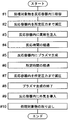
- FIG. 2 is a process explanatory diagram showing a flow of processing steps of the sterilization apparatus M1.
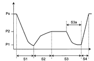
- FIG. 3 is a diagram showing a pressure change in the reaction vessel 1 in the processing step by the sterilization apparatus M1.
- Step # 1 the sterilization target Jb that is an endoscope is accommodated in a predetermined accommodation location in the reaction container 1.
- This accommodation place is set in the inner box 1b as described above.
- all of the open / close control valves 2b, 3b, 6b are closed as an initial state before the operation of the device M1 is started. That is, at this time, the outer case 1a is sealed in a state where the processing object Jb is held in the inner case 1b made of a metal plate having a large number of through holes.
- step # 2 the open / close control valve 3b is opened and then the vacuum pump 3 is driven to depressurize the reaction vessel 1 from the atmospheric pressure Ps to the predetermined pressure P1 (FIG. 3: first depressurization step S1).
- step # 3 the open / close control valve 3b is closed and the open / close control valve 2b is opened to inject a predetermined amount of drug into the reaction container 1 from the drug injection device 2.
- this drug is a peracid agent containing at least peracetic acid. Details of such a drug will be described later.
- the chemical When the chemical is injected into the reaction container 1 in a reduced pressure state, it instantly vaporizes to generate a vapor pressure, and the vapor pressure increases the pressure in the reaction container 1 to a pressure P2 (Ps> P2> P1).
- This pressure P2 is determined by conditions such as the internal volume and temperature of the reaction vessel 1, the components of the drug injected into the vessel 1, the injection amount, and the like.
- the sterilized treatment is performed by contacting the vaporized medicine all over the surface of the processing object Jb.
- the details and depth of the processing object Jb are also infiltrated and spread by the vapor pressure at the time of evaporating the drug, and a sufficient sterilization process is performed.
- step # 4 it is waited for the reaction time to elapse so that such a sterilization process is sufficiently performed (FIG. 3: sterilization process step S2).
- medical agent in the reaction container 1 in order to accelerate
- the pressure P1 is preferably set to 100 Pa or less so that the vaporized medicine can effectively penetrate into the details and the deep part of the processing object Jb.
- the pressure P2 is generally 1000 to 2500 Pa, although it depends on the injection amount of the medicine and the volume of the reaction vessel 1.
- step # 5 the high-frequency power supply device 4 is operated and placed in the reaction container 1 (specifically, between the outer box 1a and the inner box 1b).
- a plasma process for generating plasma (FIG. 3: plasma process S3) is started. Wait for a predetermined time from the start of the plasma process (step # 6), and when the predetermined time elapses, in step # 7, the vacuum pump 3 is re-driven, and the inside of the reaction vessel 1 is predetermined from the pressure P2. The pressure is reduced to the pressure P1 (FIG. 3: second decompression step S3a). Plasma generation is continued during the second decompression step. Note that the pressure P1 obtained by the second decompression step S3a does not need to be exactly the same as the pressure P1 obtained by the first decompression step S1, but it is preferable that both have the same pressure level.
- step # 8 when the inside of the reaction vessel 1 is depressurized to the pressure P1, in step # 8, the operation of the high frequency power supply device 4 is stopped and the generation of plasma is finished. Thereafter, in step # 9, the open / close control valve 6b of the outside air introduction pipe 6 is opened to introduce outside air into the reaction vessel 1, so that the pressure in the vessel 1 is set to the atmospheric pressure Ps, and the air in the reaction vessel 1 is changed. The air is replaced with new air (FIG. 3: ventilation step S4).
- step # 10 the sterilized processing target Jb is taken out from the reaction container 1, and one cycle of the sterilization process is completed.
- each step from Step # 1 to Step # 9 may be repeated a required number of times.
- what is necessary is just to repeat each step from step # 1 to step # 10, when performing the sterilization process of another process target object continuously.
- the operation of the sterilization apparatus M1 as described above can be executed by, for example, a software program stored in a readable manner in a memory attached to (or built in) the controller EC1.
- the plasma temperature generally increases in proportion to the pressure.
- the sterilization target Sb is a medical instrument, as described above, it is necessary to avoid sterilization at a high temperature as the materials used are diversified. For this reason, it is required to suppress the plasma temperature to a temperature not exceeding about 60 ° C., for example.
- the plasma temperature tends to be relatively high, particularly until the second decompression process S3a is started. .
- the high-frequency power supply from the high-frequency power supply device 4 is not continuously supplied, but output intermittently (that is, pulsed). You may make it keep the temperature of the plasma produced
- a peracid agent containing at least peracetic acid is used as a drug.
- peracetic acid CH 3 COOOH
- CH 3 COOH peracetic acid
- H 2 O 2 hydrogen peroxide
- H 2 O 2 water
- the peracid agent containing at least peracetic acid used as a drug in this embodiment is finally decomposed into carbon dioxide and water by plasma energy in the plasma step S3 after the sterilization step S2.
- These carbon dioxide and water are odorless and stable molecules.
- plasma is generated in the space between the outer box 1a and the inner box 1b of the reaction vessel 1, and the plasma acts strongly on the drug in this region, so that a high bromide-free effect is obtained.
- no plasma is generated inside the inner box 1b, but the plasma diffuses through the many through holes of the inner box 1b and the plasma is expected to have a certain effect on the drug remaining inside. it can.
- it is generally difficult to achieve sufficient odorlessness.
- the second decompression step S3a by reducing the pressure inside the reaction vessel 1 in the plasma generation state, the drug remaining in the inner box 1b passes through the through hole of the inner box 1b (plasma is generated). ) Due to the powerful action of the plasma that is drawn into the space between the outer box 1a and the inner box 1b and is generated in this region, a high bromide-free effect is obtained before being exhausted from the reaction vessel 1 to the outside. Accordingly, the exhaust gas discharged from the exhaust pipe 3d of the vacuum pump 3 toward the outside of the apparatus M1 is sufficiently deodorized, and the inside of the reaction vessel 1 becomes odorless in the subsequent ventilation step S4. Thereby, the situation which suffers from a strong pungent odor like the past is reduced greatly.
- a sterilization target object Jb is used in a process in which a peracid agent containing at least peracetic acid is used as a sterilization agent and the inside of the reaction container 1 is decompressed after sterilization with the agent.
- a peracid agent containing at least peracetic acid is used as a sterilization agent and the inside of the reaction container 1 is decompressed after sterilization with the agent.
- FIG. 4 is a configuration diagram schematically showing the overall configuration of the sterilization apparatus M2 according to the second embodiment of the present invention.
- FIG. 5 is a diagram showing a pressure change in the reaction vessel in the processing step of the sterilization apparatus M2 according to the second embodiment.
- a peracid decomposing agent or water that promotes decomposition of the peracid agent is provided on the side of the drug injection device 2 on the upstream side of the reaction container 1.
- a second injection device 7 for injecting into the reaction vessel 1 is provided.
- the second injection device 7 is connected to the side of the drug injection device 2 on the upstream side of the reaction vessel 1 via an injection pipe 7p provided with an open / close control valve 7b.
- the sterilization apparatus M2 according to the second embodiment is further provided with the second injection device 7 in that the sterilization apparatus M1 according to the first embodiment. And the configuration is different.
- the second injection device 7 and the open / close control valve 7b are connected to the controller EC2 so as to be able to exchange signals.
- the sterilization process S12 is performed.
- the pressure in the reaction container 1 is increased to the pressure P12 (Ps> P12> P11) by the vapor pressure due to the evaporation of the drug, and sterilization is performed in this process. .
- the second injection step S13 is performed after the sterilization step S12 and before the plasma step S14. Done.
- the second injection step S13 is a step of injecting a peracid decomposition agent or water that promotes decomposition of the peracid agent into the reaction vessel 1 using the second injection device 7.
- the peracid decomposing agent or water may be injected in a vaporized state. Good.
- hydrolysis of the drug see the above formula [1]
- FIG. 6 is a configuration diagram schematically showing the overall configuration of the sterilization apparatus M3 according to the third embodiment of the present invention.
- the plasma generation location by the high-frequency power supply device 4 is set in the reaction vessel 1, but in the sterilization apparatus M3 according to the third embodiment, the outside of the reaction vessel 11 is provided. Is set to
- a plasma generation chamber 8 for generating plasma is interposed between the reaction vessel 11 and the vacuum pump 3. Since the reaction vessel 11 does not generate plasma therein, there is no inner box, and only the outer box 11a made of a plate material (preferably a metal plate such as a steel plate) having a predetermined strength, rigidity, and corrosion resistance. It consists of The upstream side of the plasma generation chamber 8 is connected to the reaction vessel 11 via a connection pipe 8p, and the downstream side is connected to the vacuum pump 3 via a connection pipe 3p.
- the plasma generation chamber 8 includes a first electrode D1 and a second electrode D2 inside the case body 8a, and generates plasma in a space between the first electrode D1 and the second electrode D2. Is.
- the case body 8a, the first electrode D1, and the second electrode D2 are all formed of a conductive material having predetermined strength, rigidity, and corrosion resistance, and the first electrode D1 is electrically insulated from the case body 8a.
- the second electrode D2 is electrically connected to the case body 8a.
- the first electrode D1, and the second electrode D2 for example, a metal plate such as a steel plate is preferable.
- the case body 8a covers the inside of the plasma generation chamber 8 in an airtight manner to the outside.
- the first electrode D1 and the second electrode D2 are formed of a normal flat metal plate, and a plurality of through holes are provided so that a fluid such as gas can freely flow between the inside and the outside. It is comprised with the porous metal plate which has.
- a high-frequency power supply device 4 similar to that described above (in the first embodiment and the second embodiment) is provided on the side of the plasma generation chamber 8 in order to generate plasma in the chamber 8.
- One end side of the high-frequency circuit 4c of the high-frequency power supply device 4 is electrically connected to the case body 8a (and therefore to the second electrode D2), and the other end side is inserted through the vacuum sleeve 5 and the case body 8a. It is electrically connected to the internal first electrode D1. And by operating the high frequency power supply 4s, it is possible to generate plasma in the space formed between the first electrode D1 and the second electrode D2.
- the apparatus M3 of this embodiment includes a controller EC3 similar to that in the first embodiment described above.
- the predetermined value is generated.
- a dedicated plasma generation chamber 8 for generating plasma can be provided between the reaction vessel 11 and the vacuum pump 3.
- a powerful plasma can act on the drug.
- medical agent which remained in the reaction container 11 can be debrominated more effectively.
- FIG. 7 is a configuration diagram schematically showing an overall configuration of a sterilization apparatus M4 according to the fourth embodiment of the present invention.
- plasma generation locations are set both inside and outside the reaction vessel 1.
- the reaction vessel 1 is configured to include an outer box 1a and an inner box 1b as in the first and second embodiments, and between the reaction vessel 1 and the vacuum pump 3, A plasma generation chamber 8 similar to that in the third embodiment is interposed. Then, plasma is generated both inside the reaction vessel 1 and inside the plasma generation chamber 8 disposed outside the reaction vessel 1.
- the high frequency power supply device 14 includes the first high frequency circuit C1 that supplies the high frequency power from the high frequency power supply 14s to the reaction vessel 1 side, and the high frequency power from the high frequency power supply 14s to the plasma generation chamber 8 side. And a second high-frequency circuit C2 to be supplied.
- One end side of the first high-frequency circuit C1 is electrically connected to the outer box 1a of the reaction vessel 1, and the other end side is electrically connected to the inner box 1b of the reaction vessel 1 through the vacuum sleeve K1. Has been.
- one end side of the second high-frequency circuit C2 is electrically connected to the case body 8a (and hence to the second electrode D2), and the other end side is inserted through the vacuum sleeve K2 and the second inside the case body 8a. It is electrically connected to one electrode D1.
- the apparatus M4 of the present embodiment includes a controller EC4 similar to that in the first and third embodiments described above.
- the plasma is generated at the predetermined position in the fluid path from the position where the sterilization target Jb is stored in the reaction container 1 and the vicinity thereof to the outside of the apparatus M4.
- the location on both the inside and outside of the reaction vessel 1 it is possible to cause a wider and powerful plasma to act on the drug by setting it on the outside of the reaction vessel 1 in the exhaust path.
- plasma can be applied to the drug in multiple stages. Thereby, the chemical
- a filter using an alkaline substance such as activated carbon or calcium hydroxide may be attached to the downstream side of the exhaust pipe 3d of the vacuum pump 3.
- the present invention relates to a sterilization apparatus and a sterilization method using a peracid agent containing at least peracetic acid as a medicine, and remains in the sterilization process using a peracid agent containing at least peracetic acid as a medicine after the sterilization process step.
- the present invention can be effectively used as a sterilization apparatus and a sterilization method that can more easily perform non-bromination of peracetic acid and acetic acid.
Landscapes
- Health & Medical Sciences (AREA)
- Physics & Mathematics (AREA)
- Plasma & Fusion (AREA)
- Engineering & Computer Science (AREA)
- General Health & Medical Sciences (AREA)
- Chemical & Material Sciences (AREA)
- Life Sciences & Earth Sciences (AREA)
- Epidemiology (AREA)
- Animal Behavior & Ethology (AREA)
- Public Health (AREA)
- Veterinary Medicine (AREA)
- Chemical Kinetics & Catalysis (AREA)
- General Chemical & Material Sciences (AREA)
- Spectroscopy & Molecular Physics (AREA)
- Electromagnetism (AREA)
- Organic Chemistry (AREA)
- Toxicology (AREA)
- Apparatus For Disinfection Or Sterilisation (AREA)
Abstract
Description
尚、以下の説明では、特定の方向を意味する用語(例えば、「上」,「下」,「左」,「右」,「前」,「後」、及びそれらを含む他の用語、並びに「時計回り方向」,「反時計回り方向」など)を使用する場合があるが、それらの使用は図面を参照した発明の理解を容易にするためである。従って、本発明は、それらの用語の語義によって限定的に解釈されるべきものではない。
この図に示すように、本実施形態に係る滅菌処理装置M1は、滅菌処理対象物Jbを収容して滅菌処理を施す反応容器1と、該反応容器1内に少なくとも過酢酸を含む過酸剤を滅菌処理用薬剤として注入する薬剤注入装置2と、反応容器1内を減圧する減圧手段および反応容器1内を換気する換気手段の主要部を構成する真空ポンプ3と、滅菌処理対象物Jbの反応容器1内での収容位置及びその近傍から装置M1の外部に至る流体の経路の所定箇所にプラズマを発生させるプラズマ生成手段としての高周波電源装置4とを備えている。
反応容器1内が所定圧力P1まで減圧されると、ステップ#3で、開閉制御弁3bを閉じる一方、開閉制御弁2bを開いて薬剤注入装置2から反応容器1内に所定量の薬剤を注入する。この薬剤は、前述のように、少なくとも過酢酸を含む過酸剤である。かかる薬剤の詳細については、後述する。
・(CH3COOOH)+(H2O)→(CH3COOH)+(H2O2)……[1]
・(H2O2)→(H2O)+1/2・(O2)……[2]
・2(CH3COOH)+4(O2)→4(CO2)+4(H2O)……[3]
図4に示すように、本実施形態に係る滅菌処理装置M2では、反応容器1の上流側において、薬剤注入装置2の側方に、過酸剤の分解を促進する過酸分解剤もしくは水を反応容器1内に注入するための第2注入装置7が配設されている。
図4と図1とを対比して分かるように、第2実施形態に係る滅菌処理装置M2は、前記第2注入装置7を更に備えている点が、第1実施形態に係る滅菌処理装置M1と構成が異なっている。また、これに対応して、コントローラEC2には、前記第2注入装置7及び開閉制御弁7bが信号授受可能に接続されている。
このように、薬剤に加えて、過酸分解剤もしくは水を反応容器1内に注入することにより、薬剤の加水分解(前記式[1]参照)が促進され、残留した薬剤をより効果的に無臭化することができる。
以上のように、第2実施形態の処理プロセスでは、第1実施形態における場合と異なるのは、滅菌処理工程S12の後でプラズマ工程S14の前に、過酸分解剤もしくは水を反応容器1内に注入する第2注入工程S13が行われる点だけである。
図6は、本発明の第3実施形態に係る滅菌処理装置M3の全体構成を概略的に示す構成図である。第1実施形態,第2実施形態では、高周波電源装置4によるプラズマの生成箇所は反応容器1内に設定されていたが、この第3実施形態に係る滅菌処理装置M3では、反応容器11の外部に設定されている。
図7は、本発明の第4実施形態に係る滅菌処理装置M4の全体構成を概略的に示す構成図である。この第4実施形態に係る滅菌処理装置M4では、反応容器1の内部と外部の両方にプラズマの生成箇所が設定されている。
2 薬剤注入装置
3 真空ポンプ
4,14 高周波電源装置
7 第2注入装置
8 プラズマ生成チャンバ
Jb 滅菌処理対象物
M1,M2,M3,M4 滅菌処理装置
EC1,EC2,EC3,EC4 コントローラ
Claims (7)
- 滅菌処理対象物を収容して滅菌処理を施す反応容器と、
前記反応容器内に少なくとも過酢酸を含む過酸剤を滅菌処理用薬剤として供給する薬剤供給手段と、
前記反応容器内を減圧する減圧手段と、
前記反応容器内を換気する換気手段と、
前記滅菌処理対象物の前記反応容器内での収容位置及びその近傍から装置の外部に至る流体の経路の所定箇所にプラズマを発生させるプラズマ生成手段と、
前記薬剤による滅菌処理後に前記反応容器内が減圧される過程において、前記所定箇所がプラズマ発生状態に維持されるように、前記減圧手段およびプラズマ生成手段を制御する制御手段と、
を備えていることを特徴とする滅菌処理装置。 - 前記反応容器内に前記滅菌処理用薬剤が供給された後に、前記過酸剤の分解を促進する過酸分解剤もしくは水を前記反応容器内に供給する第2の供給手段を更に備えている、ことを特徴とする請求項1に記載の滅菌処理装置。
- 前記所定箇所は前記反応容器内に設定されている、ことを特徴とする請求項1又は2に記載の滅菌処理装置。
- 前記所定箇所は前記反応容器の外部に設定されている、ことを特徴とする請求項1又は2に記載の滅菌処理装置。
- 前記所定箇所は前記反応容器の内部と外部の両方に設定されている、ことを特徴とする請求項1又は2に記載の滅菌処理装置。
- 滅菌処理対象物を滅菌処理用の反応容器内の所定の収容位置に収容する処理対象物収容ステップと、
前記反応容器内を減圧した後、当該反応容器内に少なくとも過酢酸を含む過酸剤を滅菌処理用薬剤として供給する薬剤供給ステップと、
前記薬剤による滅菌処理後に、前記滅菌処理対象物の前記反応容器内での収容位置及びその近傍から装置の外部に至る流体の経路の所定箇所にプラズマを発生させるプラズマ生成ステップと、
前記所定箇所がプラズマ発生状態に維持された下で、前記反応容器内を再び減圧する再減圧ステップと、
前記再減圧ステップの後に、前記反応容器内を換気する換気ステップと、
を備えていることを特徴とする滅菌処理方法。 - 前記反応容器内に前記滅菌処理用薬剤が供給された後、前記過酸剤の分解を促進する過酸分解剤もしくは水を前記反応容器内に供給するステップを更に備えている、ことを特徴とする請求項6に記載の滅菌処理方法。
Priority Applications (6)
| Application Number | Priority Date | Filing Date | Title |
|---|---|---|---|
| EP13797786.4A EP2857045B1 (en) | 2012-05-28 | 2013-05-22 | Sterilization device and sterilization method using same |
| US14/404,215 US10058626B2 (en) | 2012-05-28 | 2013-05-22 | Sterilization device and sterilization method using same |
| RU2014147115A RU2669798C2 (ru) | 2012-05-28 | 2013-05-22 | Устройство для стерилизации и способ стерилизации с использованием такого устройства |
| CN201380027446.7A CN104349795A (zh) | 2012-05-28 | 2013-05-22 | 灭菌处理装置及使用该装置的灭菌处理方法 |
| JP2014518402A JP6177236B2 (ja) | 2012-05-28 | 2013-05-22 | 滅菌処理装置およびそれを用いた滅菌処理方法 |
| PL13797786T PL2857045T3 (pl) | 2012-05-28 | 2013-05-22 | Urządzenie do sterylizacji i sposób sterylizacji przy jego użyciu |
Applications Claiming Priority (2)
| Application Number | Priority Date | Filing Date | Title |
|---|---|---|---|
| JP2012120714 | 2012-05-28 | ||
| JP2012-120714 | 2012-05-28 |
Publications (1)
| Publication Number | Publication Date |
|---|---|
| WO2013179964A1 true WO2013179964A1 (ja) | 2013-12-05 |
Family
ID=49673165
Family Applications (1)
| Application Number | Title | Priority Date | Filing Date |
|---|---|---|---|
| PCT/JP2013/064188 Ceased WO2013179964A1 (ja) | 2012-05-28 | 2013-05-22 | 滅菌処理装置およびそれを用いた滅菌処理方法 |
Country Status (7)
| Country | Link |
|---|---|
| US (1) | US10058626B2 (ja) |
| EP (1) | EP2857045B1 (ja) |
| JP (1) | JP6177236B2 (ja) |
| CN (1) | CN104349795A (ja) |
| PL (1) | PL2857045T3 (ja) |
| RU (1) | RU2669798C2 (ja) |
| WO (1) | WO2013179964A1 (ja) |
Families Citing this family (12)
| Publication number | Priority date | Publication date | Assignee | Title |
|---|---|---|---|---|
| US11896204B2 (en) | 2015-09-07 | 2024-02-13 | Plasmatica Ltd. | Methods and systems for providing plasma treatments to optical surfaces |
| US11896203B2 (en) | 2015-09-07 | 2024-02-13 | Plasmatica Ltd. | Methods and systems for providing plasma treatments to optical surfaces |
| US11246480B2 (en) | 2015-09-07 | 2022-02-15 | Plasmatica Ltd. | Preventing fog on a medical device viewport |
| JP2019531105A (ja) * | 2016-06-30 | 2019-10-31 | スリーエム イノベイティブ プロパティズ カンパニー | プラズマ滅菌システム及び方法 |
| CN108686240B (zh) * | 2017-04-10 | 2022-03-04 | 山东新华医疗器械股份有限公司 | 灭菌方法和灭菌装置 |
| CN108686241B (zh) * | 2017-04-10 | 2021-03-26 | 山东新华医疗器械股份有限公司 | 灭菌方法和灭菌装置 |
| WO2020141779A1 (ko) | 2018-12-31 | 2020-07-09 | 주식회사 엔셀 | 과초산 분해 방법 및 이를 이용한 미생물의 배양방법 |
| KR102235806B1 (ko) * | 2018-12-31 | 2021-04-06 | 주식회사 엔셀 | 과초산 분해 방법 및 이를 이용한 미생물의 배양방법 |
| NL2024409B1 (en) * | 2019-12-09 | 2021-08-31 | Log10 B V | Method and apparatus for sterilizing medical instruments |
| JP7168081B2 (ja) * | 2020-03-27 | 2022-11-09 | 三浦工業株式会社 | 滅菌方法及び滅菌装置 |
| KR102619287B1 (ko) * | 2020-12-07 | 2023-12-29 | 주식회사 아이비엠솔 | 의료용 프로브 소독장치 |
| CA3216142A1 (en) | 2021-04-22 | 2022-10-27 | Shuki Wolfson | Methods and systems for providing plasma treatments to optical surfaces |
Citations (6)
| Publication number | Priority date | Publication date | Assignee | Title |
|---|---|---|---|---|
| JPS5223888A (en) * | 1975-08-18 | 1977-02-23 | Ando Toshiharu | Disinfecting method and apparatus |
| JPS573650A (en) * | 1980-06-11 | 1982-01-09 | Asahi Medical Co | Method and apparatus for removing risidual pasturizing gas from pasturized article |
| JP2780228B2 (ja) | 1990-08-31 | 1998-07-30 | アブトックス インコーポレイテッド | パルス的な殺菌剤処理によるプラズマ殺菌方法及び装置 |
| JP2000308675A (ja) * | 1999-03-31 | 2000-11-07 | Ethicon Inc | 材料の相容性を向上した改善された滅菌処理方法 |
| JP2004357888A (ja) * | 2003-06-04 | 2004-12-24 | Chiyoda Manufacturing Co Ltd | プラズマ滅菌装置及びプラズマ滅菌方法 |
| JP2011235153A (ja) * | 2007-06-29 | 2011-11-24 | Renosem Co Ltd | 過酸化水素及びオゾンを用いる混合滅菌装置 |
Family Cites Families (9)
| Publication number | Priority date | Publication date | Assignee | Title |
|---|---|---|---|---|
| JPS5367986A (en) * | 1976-11-29 | 1978-06-16 | Daido Oxygen | Method of and device for removing residual sterilizing gas from article to be sterilized |
| US5084239A (en) * | 1990-08-31 | 1992-01-28 | Abtox, Inc. | Plasma sterilizing process with pulsed antimicrobial agent treatment |
| US5656238A (en) * | 1994-10-11 | 1997-08-12 | Johnson & Johnson Medical, Inc. | Plasma-enhanced vacuum drying |
| US5869000A (en) | 1997-06-20 | 1999-02-09 | Johnson & Johnson Medical, Inc. | Partial vapor removal through exhaust port |
| KR100414360B1 (ko) * | 2002-11-08 | 2004-01-16 | 주식회사 휴먼메디텍 | 플라즈마 처리기가 부착된 멸균장치 및 멸균방법 |
| CN100502951C (zh) * | 2004-03-31 | 2009-06-24 | 株式会社汤山制作所 | 杀菌方法及杀菌装置 |
| JP4344886B2 (ja) * | 2004-09-06 | 2009-10-14 | 東京エレクトロン株式会社 | プラズマ処理装置 |
| DE102004049783B4 (de) * | 2004-10-12 | 2009-03-19 | Je Plasmaconsult Gmbh | Vorrichtung zur Bearbeitung von Gütern unter Zuhilfenahme einer elektrischen Entladung |
| JP2010200947A (ja) * | 2009-03-03 | 2010-09-16 | Noritsu Koki Co Ltd | 滅菌装置 |
-
2013
- 2013-05-22 RU RU2014147115A patent/RU2669798C2/ru active
- 2013-05-22 PL PL13797786T patent/PL2857045T3/pl unknown
- 2013-05-22 EP EP13797786.4A patent/EP2857045B1/en active Active
- 2013-05-22 CN CN201380027446.7A patent/CN104349795A/zh active Pending
- 2013-05-22 US US14/404,215 patent/US10058626B2/en active Active
- 2013-05-22 JP JP2014518402A patent/JP6177236B2/ja active Active
- 2013-05-22 WO PCT/JP2013/064188 patent/WO2013179964A1/ja not_active Ceased
Patent Citations (7)
| Publication number | Priority date | Publication date | Assignee | Title |
|---|---|---|---|---|
| JPS5223888A (en) * | 1975-08-18 | 1977-02-23 | Ando Toshiharu | Disinfecting method and apparatus |
| JPS573650A (en) * | 1980-06-11 | 1982-01-09 | Asahi Medical Co | Method and apparatus for removing risidual pasturizing gas from pasturized article |
| JP2780228B2 (ja) | 1990-08-31 | 1998-07-30 | アブトックス インコーポレイテッド | パルス的な殺菌剤処理によるプラズマ殺菌方法及び装置 |
| JP2000308675A (ja) * | 1999-03-31 | 2000-11-07 | Ethicon Inc | 材料の相容性を向上した改善された滅菌処理方法 |
| JP4526649B2 (ja) | 1999-03-31 | 2010-08-18 | エシコン・インコーポレイテッド | 滅菌処理方法 |
| JP2004357888A (ja) * | 2003-06-04 | 2004-12-24 | Chiyoda Manufacturing Co Ltd | プラズマ滅菌装置及びプラズマ滅菌方法 |
| JP2011235153A (ja) * | 2007-06-29 | 2011-11-24 | Renosem Co Ltd | 過酸化水素及びオゾンを用いる混合滅菌装置 |
Non-Patent Citations (1)
| Title |
|---|
| See also references of EP2857045A4 |
Also Published As
| Publication number | Publication date |
|---|---|
| RU2669798C2 (ru) | 2018-10-16 |
| EP2857045B1 (en) | 2018-08-01 |
| JP6177236B2 (ja) | 2017-08-09 |
| RU2014147115A (ru) | 2016-07-20 |
| JPWO2013179964A1 (ja) | 2016-01-21 |
| US20150209461A1 (en) | 2015-07-30 |
| CN104349795A (zh) | 2015-02-11 |
| EP2857045A1 (en) | 2015-04-08 |
| US10058626B2 (en) | 2018-08-28 |
| EP2857045A4 (en) | 2016-01-20 |
| PL2857045T3 (pl) | 2019-02-28 |
Similar Documents
| Publication | Publication Date | Title |
|---|---|---|
| JP6177236B2 (ja) | 滅菌処理装置およびそれを用いた滅菌処理方法 | |
| JP5006966B2 (ja) | 過酸化水素及びオゾンを用いる滅菌方法 | |
| KR101250748B1 (ko) | 저온 대기압 플라즈마를 이용한 의료용 소형 멸균장치 | |
| TR201900045T4 (tr) | Steri̇li̇zasyon yöntemi̇. | |
| JP2007506484A (ja) | 改良されたオゾン滅菌方法 | |
| KR20120028413A (ko) | 과산화수소, 오존 및 저온 플라즈마를 이용한 소독 멸균장치 및 방법 | |
| KR100913632B1 (ko) | 오존과 플라즈마에 의한 의료용 멸균 방법 및 장치 | |
| JP4360049B2 (ja) | 過酸化水素滅菌装置 | |
| CN113195007B (zh) | 灭菌方法以及灭菌装置 | |
| WO2007080907A1 (ja) | 滅菌方法およびプラズマ滅菌装置 | |
| KR101453767B1 (ko) | 플라즈마 멸균장치 및 멸균방법 | |
| KR101298730B1 (ko) | 플라즈마 멸균 방법 | |
| KR20120093790A (ko) | 과산화수소 및 오존을 이용한 의료용 멸균장치 | |
| JP3704129B2 (ja) | プラズマ滅菌処理方法 | |
| JP6930684B1 (ja) | 滅菌方法及び滅菌装置 | |
| JP2021153911A (ja) | 滅菌方法及び滅菌装置 | |
| KR101068629B1 (ko) | 멸균장치 및 방법 | |
| KR20170043193A (ko) | 플라즈마 상태의 과산화수소 증기를 이용하여 멸균 오브젝트를 멸균하는 의료기기용 멸균장치 | |
| JP2004357888A (ja) | プラズマ滅菌装置及びプラズマ滅菌方法 | |
| KR20140049347A (ko) | 멸균방법 | |
| JP6436295B2 (ja) | 過酸化水素ガス滅菌装置 | |
| JP2015229034A (ja) | ガス滅菌器 | |
| WO2021192330A1 (ja) | 滅菌方法及び滅菌装置 | |
| JP2021153912A (ja) | 滅菌方法及び滅菌装置 | |
| RU2772541C2 (ru) | Способ низкотемпературной плазменной вакуумной стерилизации изделий |
Legal Events
| Date | Code | Title | Description |
|---|---|---|---|
| 121 | Ep: the epo has been informed by wipo that ep was designated in this application |
Ref document number: 13797786 Country of ref document: EP Kind code of ref document: A1 |
|
| ENP | Entry into the national phase |
Ref document number: 2014518402 Country of ref document: JP Kind code of ref document: A |
|
| WWE | Wipo information: entry into national phase |
Ref document number: 14404215 Country of ref document: US Ref document number: 2013797786 Country of ref document: EP |
|
| NENP | Non-entry into the national phase |
Ref country code: DE |
|
| ENP | Entry into the national phase |
Ref document number: 2014147115 Country of ref document: RU Kind code of ref document: A |