WO2013180055A1 - Sonde ultrasonore - Google Patents
Sonde ultrasonore Download PDFInfo
- Publication number
- WO2013180055A1 WO2013180055A1 PCT/JP2013/064609 JP2013064609W WO2013180055A1 WO 2013180055 A1 WO2013180055 A1 WO 2013180055A1 JP 2013064609 W JP2013064609 W JP 2013064609W WO 2013180055 A1 WO2013180055 A1 WO 2013180055A1
- Authority
- WO
- WIPO (PCT)
- Prior art keywords
- vibration
- passage
- cross
- longitudinal axis
- ultrasonic probe
- Prior art date
- Legal status (The legal status is an assumption and is not a legal conclusion. Google has not performed a legal analysis and makes no representation as to the accuracy of the status listed.)
- Ceased
Links
Images







Classifications
-
- A—HUMAN NECESSITIES
- A61—MEDICAL OR VETERINARY SCIENCE; HYGIENE
- A61B—DIAGNOSIS; SURGERY; IDENTIFICATION
- A61B17/00—Surgical instruments, devices or methods
- A61B17/32—Surgical cutting instruments
- A61B17/320068—Surgical cutting instruments using mechanical vibrations, e.g. ultrasonic
-
- A—HUMAN NECESSITIES
- A61—MEDICAL OR VETERINARY SCIENCE; HYGIENE
- A61B—DIAGNOSIS; SURGERY; IDENTIFICATION
- A61B17/00—Surgical instruments, devices or methods
- A61B2017/0046—Surgical instruments, devices or methods with a releasable handle; with handle and operating part separable
- A61B2017/00473—Distal part, e.g. tip or head
-
- A—HUMAN NECESSITIES
- A61—MEDICAL OR VETERINARY SCIENCE; HYGIENE
- A61B—DIAGNOSIS; SURGERY; IDENTIFICATION
- A61B17/00—Surgical instruments, devices or methods
- A61B17/32—Surgical cutting instruments
- A61B17/320068—Surgical cutting instruments using mechanical vibrations, e.g. ultrasonic
- A61B2017/32007—Surgical cutting instruments using mechanical vibrations, e.g. ultrasonic with suction or vacuum means
-
- A—HUMAN NECESSITIES
- A61—MEDICAL OR VETERINARY SCIENCE; HYGIENE
- A61B—DIAGNOSIS; SURGERY; IDENTIFICATION
- A61B17/00—Surgical instruments, devices or methods
- A61B17/32—Surgical cutting instruments
- A61B17/320068—Surgical cutting instruments using mechanical vibrations, e.g. ultrasonic
- A61B2017/320072—Working tips with special features, e.g. extending parts
- A61B2017/320073—Working tips with special features, e.g. extending parts probe
-
- A—HUMAN NECESSITIES
- A61—MEDICAL OR VETERINARY SCIENCE; HYGIENE
- A61B—DIAGNOSIS; SURGERY; IDENTIFICATION
- A61B17/00—Surgical instruments, devices or methods
- A61B17/32—Surgical cutting instruments
- A61B17/320068—Surgical cutting instruments using mechanical vibrations, e.g. ultrasonic
- A61B2017/320072—Working tips with special features, e.g. extending parts
- A61B2017/320074—Working tips with special features, e.g. extending parts blade
-
- A—HUMAN NECESSITIES
- A61—MEDICAL OR VETERINARY SCIENCE; HYGIENE
- A61B—DIAGNOSIS; SURGERY; IDENTIFICATION
- A61B17/00—Surgical instruments, devices or methods
- A61B17/32—Surgical cutting instruments
- A61B17/320068—Surgical cutting instruments using mechanical vibrations, e.g. ultrasonic
- A61B2017/320084—Irrigation sleeves
-
- A—HUMAN NECESSITIES
- A61—MEDICAL OR VETERINARY SCIENCE; HYGIENE
- A61B—DIAGNOSIS; SURGERY; IDENTIFICATION
- A61B17/00—Surgical instruments, devices or methods
- A61B17/32—Surgical cutting instruments
- A61B17/320068—Surgical cutting instruments using mechanical vibrations, e.g. ultrasonic
- A61B2017/320089—Surgical cutting instruments using mechanical vibrations, e.g. ultrasonic node location
-
- A—HUMAN NECESSITIES
- A61—MEDICAL OR VETERINARY SCIENCE; HYGIENE
- A61B—DIAGNOSIS; SURGERY; IDENTIFICATION
- A61B17/00—Surgical instruments, devices or methods
- A61B17/32—Surgical cutting instruments
- A61B17/320068—Surgical cutting instruments using mechanical vibrations, e.g. ultrasonic
- A61B2017/320098—Surgical cutting instruments using mechanical vibrations, e.g. ultrasonic with transverse or torsional motion
-
- A—HUMAN NECESSITIES
- A61—MEDICAL OR VETERINARY SCIENCE; HYGIENE
- A61B—DIAGNOSIS; SURGERY; IDENTIFICATION
- A61B2217/00—General characteristics of surgical instruments
- A61B2217/002—Auxiliary appliance
- A61B2217/005—Auxiliary appliance with suction drainage system
Definitions
- the present invention relates to an ultrasonic probe capable of transmitting ultrasonic vibration along a longitudinal axis from a proximal direction to a distal direction.
- Patent Document 1 discloses an ultrasonic probe extending along a longitudinal axis.
- This ultrasonic probe is capable of transmitting ultrasonic vibration generated by an ultrasonic transducer, which is an ultrasonic generator, along the longitudinal axis from the proximal direction to the distal direction.
- a distal treatment section for treating a treatment target such as a living tissue is provided at the distal end of the ultrasonic probe.
- the treatment target is resected by the distal treatment section.
- a suction passage extending along the longitudinal axis from the distal end portion to the proximal direction side is formed inside the ultrasonic probe. The excised treatment target is sucked through the suction passage.
- An ultrasonic probe in which a passage such as a suction passage is formed along a longitudinal axis as shown in the above-mentioned Patent Document 1 generally has a cross section along a longitudinal axis of a columnar member by gun drilling. It is manufactured by forming a perfect circular hole. In such a gun drilling process, it is difficult to form a hole that becomes a passage such as a suction passage from the distal end to the proximal end in an ultrasonic probe having a small outer diameter and a large dimension along the longitudinal axis. .
- gun drilling can only form holes with a cross-sectional shape that is perpendicular to the longitudinal axis. That is, by increasing the cross-sectional area of the passage perpendicular to the longitudinal axis, performance such as suction is improved in the treatment, but in gun drilling, the sectional shape of the passage perpendicular to the longitudinal axis is not a perfect circle, for example, an ellipse Cannot be formed in the columnar member.
- the present invention has been made paying attention to the above-mentioned problems, and an object of the present invention is to provide an ultrasonic probe that can be easily manufactured regardless of the type of passages provided therein.
- an aspect of the present invention provides an ultrasonic probe capable of transmitting ultrasonic vibration along a longitudinal axis from a proximal direction to a distal direction, and the base from the distal end portion of the ultrasonic probe.
- a path defining portion that defines a path inside the ultrasonic probe, and a plurality of coupled vibration members coupled to each other, the first antinode position of the ultrasonic vibration and the first Each of the coupled vibration members extends along the longitudinal axis between the second antinode position of the ultrasonic vibration on the distal direction side of the antinode position, and the ultrasonic wave
- Each of the connected vibration members is vibrated in the same vibration mode as the other connected vibration members in a state in which vibration is transmitted, and is provided in the passage defining portion, and a groove is formed in each of the connected vibration members. It is a groove defining part that regulates
- FIG. 1 is a schematic view showing an ultrasonic treatment apparatus according to a first embodiment of the present invention. It is sectional drawing which shows schematically the structure of the vibration generation unit which concerns on 1st Embodiment.
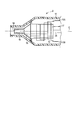
- 1 is a cross-sectional view schematically showing an ultrasonic probe according to a first embodiment.
- 1 is a perspective view schematically showing an ultrasonic probe according to a first embodiment. It is a perspective view showing the ultrasonic probe concerning a 1st embodiment roughly disassembled for every member.
- FIG. 6 is a sectional view taken along line VI-VI in FIG. 4. It is sectional drawing which shows schematically the cross section perpendicular
- FIG. 10 is a cross-sectional view showing an example of a cross section taken along line XX of FIG. 9.
- FIG. 10 is a cross-sectional view showing another example of a cross section taken along line XX of FIG. 9.
- FIG. 1 is a diagram showing an ultrasonic treatment apparatus 1 of the present embodiment.
- the ultrasonic treatment apparatus 1 has a longitudinal axis C.
- one of the two directions parallel to the longitudinal axis C is the distal direction (the direction of the arrow X1 in FIG. 1), and the direction opposite to the distal direction is the proximal direction (the direction of the arrow X2 in FIG. 1).
- the ultrasonic treatment apparatus 1 includes a vibration generating unit 2 and a cylindrical ultrasonic probe 3 extending along the longitudinal axis C.
- the vibration generating unit 2 includes a vibrator case 11. One end of the cable 5 is connected to the base end of the vibrator case 11. The other end of the cable 5 is connected to the power supply unit 6.
- the power supply unit 6 includes an ultrasonic wave generation current supply unit 7 and a high frequency current supply unit 8.
- An input unit 9 is connected to the power supply unit 6.
- FIG. 2 is a diagram showing the configuration of the vibration generating unit 2.
- an ultrasonic transducer 12 that is a vibration generating unit including a piezoelectric element that converts current into ultrasonic vibration is provided inside the transducer case 11.
- One end of electrical wires 13A and 13B is connected to the ultrasonic transducer 12.
- the electrical wirings 13 ⁇ / b> A and 13 ⁇ / b> B pass through the inside of the cable 5, and the other end is connected to the ultrasonic generation current supply unit 7 of the power supply unit 6.
- a horn 15 that expands the amplitude of the ultrasonic vibration is connected to the tip side of the ultrasonic vibrator 12.
- the horn 15 is attached to the vibrator case 11.
- One end of an electrical wiring 17 is connected to the ultrasonic transducer 12.
- the electrical wiring 17 passes through the inside of the cable 5, and the other end is connected to the high-frequency current supply unit 8 of the power supply unit 6.
- a high-frequency current is transmitted from the high-frequency current supply unit 8 to the ultrasonic transducer 12 and the horn 15 via the electrical wiring 17.
- a space 18 is formed around the longitudinal axis C in the ultrasonic transducer 12 and the horn 15.
- a female screw part 19 is formed at the tip of the inner peripheral surface of the horn 15.
- One end of a tube member 21 is connected to the space 18. As shown in FIG. 1, the tube member 21 extends to the outside of the transducer case 11, and the other end is connected to the suction unit 22.
- the suction unit 22 is electrically connected to the input unit 9.
- the ultrasonic probe 3 includes a multi-member vibrating portion 31 and a single-member vibrating portion 32 provided on the proximal direction side from the multi-member vibrating portion 31.
- the distal treatment section 30 is located at the distal end of the multi-member vibration section 31.
- the multi-member vibration part 31 includes a plurality of coupled vibration members 33 formed of titanium or the like.
- the multi-member vibration part 31 includes two members, and includes a connected vibration member 33A as a first member and a connected vibration member 33B as a second member.
- the single member vibration part 32 is comprised only from the single integral vibration member 35 formed from titanium etc. As shown in FIG.
- a passage 37 is defined by a passage defining portion 38.
- the passage 37 extends from the distal end portion (the distal treatment portion 30) of the ultrasonic probe 3 to the proximal direction side. In the present embodiment, it extends to the proximal end of the ultrasonic probe 3 along the longitudinal axis C.
- Two openings 39 ⁇ / b> A and 39 ⁇ / b> B that open to the outside are provided on the outer peripheral portion of the distal end portion (tip treatment portion 30) of the ultrasonic probe 3.
- the openings 39A and 39B are located away from each other in the direction around the longitudinal axis.
- Each of the openings 39 ⁇ / b> A and 39 ⁇ / b> B communicates with the passage 37.
- a male screw portion 41 is provided integrally with the integral vibration member 35 on the outer peripheral portion of the proximal end portion of the ultrasonic probe 3.
- the integral vibration member 35 of the ultrasonic probe 3 is attached to the distal direction side of the horn 15.
- the male screw portion 41 is located on the proximal direction side of the single member vibration portion 32 and on the inner circumferential direction side of the horn 15.
- the male screw portion 41 is a connecting portion that directly connects the vibration generating unit 2 to the proximal direction side of the single member vibrating portion 32.
- the integral vibration member 35 is formed in a cylindrical shape, and a part of the passage 37 is defined by the inner peripheral portion of the integral vibration member 35. That is, the inner peripheral portion of the integral vibration member 35 is a part of the passage defining portion 38.
- a female screw portion 42 is formed on the inner peripheral portion of the distal end portion of the integrated vibration member 35.
- Engagement protrusions 43A and 43B projecting toward the coupling vibration member 33B are provided at the base end of the coupling vibration member 33A. Further, engagement grooves 45A and 45B are provided at the base end portion of the coupling vibration member 33B.
- the engaging protrusion 43A can engage with the engaging groove 45A, and the engaging protrusion 43B can engage with the engaging groove 45B.
- the male screw component 47A is provided integrally with the coupling vibration member 33A
- the male screw component 47B is provided integrally with the connection vibration member 33B.
- the male screw portion 48 is formed by the male screw constituting portions 47A and 47B.
- the coupled vibration members 33 ⁇ / b> A and 33 ⁇ / b> B are attached to the distal direction side of the integral vibration member 35.
- the male screw portion 48 is located on the proximal side with respect to the plural member vibration portion 31 and on the inner circumferential side with respect to the integral vibration member 35. ing. As described above, the male screw portion 48 is a connecting portion that directly connects the single member vibrating portion 32 to the proximal direction side of the multi-member vibrating portion 31.
- the coupling vibration member 33A is provided with notches 51A and 51B. Further, the coupling vibration member 33B is provided with notches 52A and 52B. In a state where the coupled vibration members 33A and 33B are coupled to each other, an opening 39A is formed by the notches 51A and 52A. Further, in the state where the coupled vibration members 33A and 33B are coupled to each other, the opening 39B is formed by the notches 51B and 52B.
- the ultrasonic probe 3 is coupled to the vibration generating unit 2 by attaching the integral vibration member 35 to the horn 15 and attaching the coupled vibration members 33A and 33B to the integral vibration member 35.
- the base end of the passage 37 communicates with the space portion 18 provided inside the horn 15 and the ultrasonic transducer 12.
- the ultrasonic probe 3 can transmit the ultrasonic vibration generated by the ultrasonic transducer 12 along the longitudinal axis C from the proximal direction to the distal direction. is there. By transmitting the ultrasonic vibration, the ultrasonic probe 3 performs vertical vibration in which the transmission direction and the vibration direction are parallel to the longitudinal axis C. In the state where the ultrasonic probe 3 is connected to the vibration generating unit 2, the high-frequency current transmitted to the horn 15 is transmitted along the longitudinal axis C to the distal treatment section 30.
- the base end of the multiple member vibrating portion 31 (the connection portion between the multiple member vibrating portion 31 and the single member vibrating portion 32) is the first antinode of the ultrasonic vibration.
- the position (anti-node position) A1 is reached, and the distal end of the multi-member vibration portion 31 is the second antinode position A2 of ultrasonic vibration on the distal direction side from the first antinode position A1.
- the multi-member vibration part 31 is formed by connecting the connection vibration members 33A and 33B to each other.
- the connecting vibration members 33A and 33B extend along the longitudinal axis C between the first antinode position A1 and the second antinode position A2.
- the ultrasonic vibration is transmitted from the single member vibrating portion 32 to the multiple member vibrating portion 31 at the first antinode position A1. That is, at the first antinode position A1, the base end of the multi-member vibrating portion 31 and the tip of the single member vibrating portion 32 are connected.
- the second antinode position A2 is the tip of the ultrasonic probe 3.
- Each connected vibration member 33A, 33B vibrates in the same vibration mode as the other connected vibration members 33A, 33B in a state where ultrasonic vibration is transmitted to the ultrasonic probe 3.
- the integral vibration member 35 vibrates in the same vibration mode as the coupled vibration members 33 ⁇ / b> A and 33 ⁇ / b> B in a state where ultrasonic vibration is transmitted to the ultrasonic probe 3.
- each of the connecting vibration members 33A and 33B and the integrated vibration member 35 is designed to perform a longitudinal vibration with a frequency of 47 Hz.
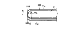
- the passage defining portion 38 of the ultrasonic probe 3 includes a groove defining portion 55 that defines the groove 53A in the connecting vibration member 33A and the groove 53B in the connecting vibration member 33B.
- a part of the passage 37 is formed by the grooves 53A and 53B. That is, the groove 53 ⁇ / b> A of the coupled vibration member 33 ⁇ / b> A forms a part of the passage 37 inside the multi-member vibration portion 31 in cooperation with the groove 53 ⁇ / b> B of the coupled vibration member 33 ⁇ / b> B.
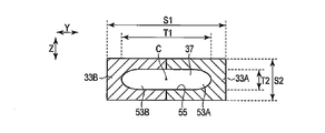
- FIG. 6 is a cross-sectional view taken along line VI-VI in FIG.
- the multi-member vibrating portion 31 has an elliptical cross-sectional shape in a cross section perpendicular to the longitudinal axis C.
- the first sectional dimension S1 in the first vertical direction (the direction of the arrow Y in FIGS. 4 and 6) perpendicular to the longitudinal axis C is It becomes larger than the second cross-sectional dimension S2 in the second vertical direction (the direction of arrow Z in FIGS. 4 and 6) perpendicular to the axis C and perpendicular to the first vertical direction.
- an opening 39A opens toward one side in the second vertical direction
- an opening 39B opens toward the other side in the second vertical direction.
- the passage cross-sectional shape of the passage 37 is formed to be similar to the cross-sectional shape of the multi-member vibration portion 31.
- the first passage dimension T1 in the first vertical direction of the passage 37 is the second passage dimension in the second vertical direction of the passage 37. It is larger than T2. That is, in the cross section perpendicular to the longitudinal axis C of the multi-member vibration portion 31, the first passage dimension T1 in the first vertical direction of the passage 37 is the second passage dimension in the second vertical direction of the passage 37.
- Grooves 53A and 53B are defined in the respective connecting vibration members 33A and 33B so that an elliptical passage cross-sectional shape larger than T2 is formed.
- the first ratio R1 of the first passage dimension T1 of the passage 37 with respect to the first sectional dimension S1 of the multi-member vibration part 31 is the second passage of the passage 37 with respect to the second cross-sectional dimension S2 of the multi-member vibration part 31. It is equal to the second ratio R2 of the dimension T2.
- the integral vibration member 35 is formed.
- the integral vibration member 35 is formed by punching a columnar member by gun drilling or the like.
- a part of the passage 37 is formed inside the integral vibration member 35 by gun drilling.
- the female screw portion 42 is provided in the integral vibration member 34, and the male screw portion 41 is provided integrally with the integral vibration member 35.
- the connecting vibration members 33A and 33B are formed.
- the groove 53A is formed by cutting or the like in the coupled vibration member 33A
- the groove 53B is formed by cutting or the like in the coupled vibration member 33B.
- the engagement protrusions 43A and 43B and the notches 51A and 51B are provided on the coupled vibration member 33A, and the male screw component 47A is provided integrally with the coupled vibration member 33A.
- the engagement grooves 45A and 45B and the notches 52A and 52B are provided in the coupled vibration member 33B, and the male screw constituting portion 47B is provided integrally with the coupled vibration member 33B.
- the respective engaging protrusions 43A and 43B engage with the corresponding engaging grooves 45A and 45B, respectively, and connect the connecting vibration members 33A and 33B to each other.
- the multi-member vibration part 32 is formed.
- the grooves 53A and 53B of each of the coupled vibration members 33A and 33B cooperate with the grooves (53A and 53B) of the other coupled vibration members (33A and 33B) to pass through the inside of the multi-member vibration unit 31. 37 is formed.
- the passage cross-sectional shape of the passage 37 is such that the first passage dimension T 1 in the first vertical direction of the passage 37 is the second passage direction in the second vertical direction of the passage 37. 2 is formed in an elliptical shape larger than the passage dimension T2.
- the male screw portion 48 is formed by the male screw constituting portions 47A and 47B.
- an opening 39A is formed by the notches 51A and 52A
- an opening 39B is formed by the notches 51B and 52B.
- the connecting vibration members 33A and 33B are attached to the distal direction side of the integral vibration member 35. Thereby, the ultrasonic probe 3 is manufactured.
- the groove 53A is formed in the coupling vibration member 33A
- the groove 53B is formed in the coupling vibration member 33B
- the coupling vibration members 33A and 33B are coupled to each other.
- a part of the passage 37 whose cross section perpendicular to the longitudinal axis C has a non-circular shape is formed inside the multi-member vibration portion 31 by the grooves 53A and 53B. That is, a part of the passage 37 whose cross section perpendicular to the longitudinal axis C is not a perfect circle is formed inside the multi-member vibrating portion 31 without performing the operation of forming the hole in the columnar member.
- Forming grooves 53A and 53B corresponding to the respective connecting vibration members 33A and 33B and connecting the connection vibration members 33A and 33B to each other is compared to forming a hole in the columnar member without using gun drilling. Done efficiently. Therefore, the manufacturing time and manufacturing cost of the ultrasonic probe 3 are reduced, and the ultrasonic probe 3 can be easily manufactured even when the passage 37 has a portion whose path cross-sectional shape perpendicular to the longitudinal axis C is not a perfect circle.
- the ultrasonic treatment apparatus 1 and the ultrasonic probe 3 of this embodiment will be described.
- a treatment of a living tissue (treatment target) such as a mesentery (mesentery)
- a current is supplied from the ultrasonic current supply unit 7 to the ultrasonic transducer 12 by an operation of the input unit 9.
- ultrasonic vibration is generated in the ultrasonic vibrator 12.
- ultrasonic vibration is transmitted along the longitudinal axis C to the distal treatment section 30 of the ultrasonic probe 3, and the ultrasonic probe 3 performs vertical vibration.
- a high-frequency current is supplied from the high-frequency current supply unit 8 by an operation on the input unit 9.
- the high frequency current is transmitted to the distal treatment section 30 of the ultrasonic probe 3, and the high frequency current is discharged from the distal treatment section 30.
- the distal treatment section 30 is brought into contact with the living tissue in this state, the living tissue is burned by the high-frequency current, and the living tissue is coagulated and cut.
- the first sectional dimension S1 in the first vertical direction perpendicular to the longitudinal axis C is the longitudinal axis C.
- a second cross-sectional dimension S2 in the second vertical direction perpendicular to the first vertical direction is formed in a shape suitable for the treatment to be treated.
- the single member vibrating portion 32 is connected to the proximal direction side of the multiple member vibrating portion 31 at the first antinode position A1. Accordingly, at the first antinode position A1 located at the base end of the multi-member vibration portion 31 (the tip of the single-member vibration portion 32), the plurality of coupled vibration members 33A, 33A, The number of members that vibrate changes to the state in which 33B vibrates. At the position where the number of vibrating members changes, the ultrasonic vibration is easily affected by the stress in the direction perpendicular to the longitudinal axis C. When the ultrasonic vibration is affected by the stress, the vibration mode of the ultrasonic vibration changes, and the ultrasonic probe 3 does not appropriately perform longitudinal vibration. Thereby, the ultrasonic vibration is not properly transmitted to the distal treatment section 30 of the ultrasonic probe 3.
- the number of members that vibrate at the first antinode position A1 is set to change.
- the displacement due to the vibration is maximum, but the stress in the direction perpendicular to the longitudinal axis C is zero. Therefore, no stress acts on the ultrasonic vibration at the first antinode position A1 where the number of vibrating members changes.
- the vibration mode does not change due to a change in the number of vibrating members, and the ultrasonic probe 3 appropriately performs longitudinal vibration. Thereby, the ultrasonic vibration is appropriately transmitted to the distal treatment section 30 of the ultrasonic probe 3.
- the suction unit 22 is driven by the operation of the input unit 9. Then, the liquid is sucked from the opening 39A or the opening 39B of the distal treatment section 30.
- the liquid sucked from the opening 39 ⁇ / b> A or the opening 38 ⁇ / b> B passes through the passage 37, the space 18, and the inside of the tube member 21.
- the suction unit 22 is sucked and collected.
- the passage cross-sectional shape of the passage 37 is such that the first passage dimension T 1 in the first vertical direction of the passage 37 is the second vertical direction of the passage 37. Is formed in an oval shape larger than the second passage dimension T2. That is, in the cross section perpendicular to the longitudinal axis C of the multi-member vibrating portion 31, the passage cross-sectional shape of the passage 37 corresponds to the first cross-sectional dimension S1 and the second cross-sectional dimension S2 of the cross-sectional shape of the multi-member vibrating portion 31. Is formed.
- the passage cross-sectional shape of the passage 37 in the multi-member vibration part 31 is a perfect circle or the like that does not correspond to the first cross-sectional dimension S1 and the second cross-sectional dimension S2 of the cross-sectional shape of the multi-member vibration part 31.
- the passage cross-sectional area perpendicular to the longitudinal axis C of the passage 37 in the multi-member vibration portion 31 is increased.
- the passage cross-sectional area perpendicular to the longitudinal axis C in the multi-member vibrating portion 31 is increased, so that the suction performance of the liquid or the like generated in the treatment is improved.
- the passage cross-sectional shape of the passage 37 is similar to the cross-sectional shape of the multi-member vibration portion 31.
- the first ratio R1 of the first passage dimension T1 of the passage 37 with respect to the first sectional dimension S1 of the plurality of member vibration parts 31 in the cross section perpendicular to the longitudinal axis C of the plurality of member vibration parts 31 is the plurality of member vibrations.
- This is equal to the second ratio R2 of the second passage dimension T2 of the passage 37 with respect to the second cross-sectional dimension S2 of the portion 31.
- the passage cross-sectional area perpendicular to the longitudinal axis C of the passage 37 in the multi-member vibration portion 31 is further increased. Therefore, the liquid suction performance is further improved in the treatment.
- the ultrasonic probe 3 configured as described above has the following effects. That is, the multi-member vibration part 31 of the ultrasonic probe 3 is manufactured by forming grooves 53A and 53B corresponding to the respective connection vibration members 33A and 33B and connecting the connection vibration members 33A and 33B to each other.
- channel 53A, 53B forms a part of channel
- Forming grooves 53A and 53B corresponding to the respective connecting vibration members 33A and 33B and connecting the connection vibration members 33A and 33B to each other is compared to forming a hole in the columnar member without using gun drilling. Done efficiently. Therefore, the manufacturing time and manufacturing cost of the ultrasonic probe 3 can be reduced, and the ultrasonic probe 3 can be easily manufactured even when the passage 37 has a portion whose cross-sectional shape perpendicular to the longitudinal axis C is not a perfect circle. be able to.
- the boundary between the single member vibrating portion 32 and the multiple member vibrating portion 31 is located at the first antinode position A1. That is, it is set in a state where the number of members that vibrate at the first antinode position A1 changes.
- the vibration mode does not change due to a change in the number of vibrating members, and the ultrasonic probe 3 appropriately performs longitudinal vibration. Thereby, even when it has a part from which the number of members to vibrate changes, ultrasonic vibration can be appropriately transmitted to tip treatment part 30 of ultrasonic probe 3.
- the cross-sectional shape perpendicular to the longitudinal axis C of the multi-member vibrating portion 31 is elliptical
- the cross-sectional shape of the passage 37 in the cross-section perpendicular to the longitudinal axis C of the multi-member vibrating portion 31 is elliptical.
- the cross-sectional shape perpendicular to the longitudinal axis C of the multi-member vibration portion 31 may be a rectangular shape.
- the first perpendicular direction perpendicular to the longitudinal axis C (the direction of the arrow Y in FIG. 7).
- the cross-sectional shape of the passage 37 is similar to the cross-sectional shape of the multi-member vibrating portion 31 in the cross section perpendicular to the longitudinal axis C of the multi-member vibrating portion 31. Then, in the cross section perpendicular to the longitudinal axis C of the multi-member vibration portion 31, the first passage dimension T1 in the first vertical direction of the passage 37 is the second passage dimension in the second vertical direction of the passage 37. It is larger than T2. That is, in the cross section perpendicular to the longitudinal axis C of the multi-member vibration portion 31, the first passage dimension T1 in the first vertical direction of the passage 37 is the second passage dimension in the second vertical direction of the passage 37.
- Grooves 53A and 53B are defined in the respective connecting vibration members 33A and 33B so that a rectangular passage cross-sectional shape larger than T2 is formed.
- the first ratio R1 of the first passage dimension T1 of the passage 37 with respect to the first sectional dimension S1 of the multi-member vibration part 31 is the second passage of the passage 37 with respect to the second cross-sectional dimension S2 of the multi-member vibration part 31. It is equal to the second ratio R2 of the dimension T2.
- the cross-sectional shape of the passage 37 is similar to the cross-sectional shape of the multi-member vibrating portion 31 in the cross section perpendicular to the longitudinal axis C of the multi-member vibrating portion 31.
- the cross-sectional shape perpendicular to the longitudinal axis C of the multi-member vibrating portion 31 is rectangular, and the cross-section perpendicular to the longitudinal axis C of the multi-member vibrating portion 31 is
- the passage cross-sectional shape of the passage 37 may be formed in an elliptical shape.
- the first perpendicular direction perpendicular to the longitudinal axis C (the direction of the arrow Y in FIG. 8).
- the first passage dimension T1 in the first vertical direction of the passage 37 is the second passage dimension in the second vertical direction of the passage 37. It is larger than T2.
- the passage cross-sectional shape of the passage 37 is the first cross-sectional shape of the multi-member vibration portion 31. What is necessary is just to be formed corresponding to cross-sectional dimension S1 and 2nd cross-sectional dimension S2. Thereby, the passage cross-sectional shape of the passage 37 in the multi-member vibration portion 31 is a perfect circle or the like that does not correspond to the first cross-sectional dimension S1 and the second cross-sectional dimension S2 of the cross-sectional shape of the multi-member vibration portion 31.
- the passage cross-sectional area perpendicular to the longitudinal axis C of the passage 37 in the multi-member vibration portion 31 is increased.
- the liquid suction performance is improved in the treatment.
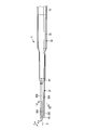
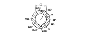
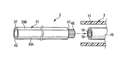
- FIG. 9 is a view showing the ultrasonic probe 3 of this embodiment
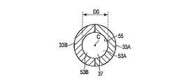
- FIG. 10A is an example of a cross section taken along line XX in FIG. 9
- FIG. 10B is a cross section taken along line XX in FIG. It is another example of.
- the connecting vibration members 33A and 33B are connected between the first antinode position A1 and the second antinode position A2. Is extended along the longitudinal axis C. Then, the ultrasonic vibration is transmitted from the single member vibrating portion 32 to the multiple member vibrating portion 31 at the first antinode position A1.
- the single member vibration part 32 is connected to the proximal direction side of the multiple member vibration part 31 at the first antinode position A1.
- the second antinode position A2 is the tip of the ultrasonic probe 3.
- the multi-member vibrating portion 31 of the ultrasonic probe 3 has a reference dimension L0 along the longitudinal axis C from the first antinode position A1 to the second antinode position A2.
- the cross-sectional shape perpendicular to the longitudinal axis C of the multi-member vibrating portion 31 is formed in a perfect circle. Further, in the cross section perpendicular to the longitudinal axis C of the multi-member vibration portion 31, the passage cross-sectional shape of the passage 37 is also formed in a perfect circle.
- the cross-sectional shape of the passage 37 in the multi-member vibration portion 31 has a diameter D0 that is 1/100 or more of the reference dimension L0 along the longitudinal axis C from the first antinode position A1 to the second antinode position A2. .
- the diameter D0 is equal to or greater than 1/100 of the reference dimension L0 along the longitudinal axis C from the first antinode position A1 to the second antinode position A2.
- Grooves 53 ⁇ / b> A and 53 ⁇ / b> B are defined in the coupling vibration members 33 ⁇ / b> A and 33 ⁇ / b> B, respectively.
- the connecting vibration members 33A and 33B are connected by the engaging protrusions 43A and 43B and the engaging grooves 45A and 45B.
- the present invention is not limited to this.
- stepped portions 33A1 and 33A2 are provided on the connecting vibration member 33A
- stepped portions 33B1 and 33B2 are provided on the connecting vibration member 33B. It may be provided. Then, by engaging the stepped portion 33A1 and the stepped portion 33B1 and engaging the stepped portion 33A2 and the stepped portion 33B2, the coupled vibration members 33A and 33B are coupled in a positioned state.
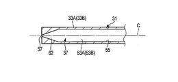
- the openings 39A and 39B are not provided, and the opening 57 that opens in the distal direction at the distal end (the distal treatment section 30) of the ultrasonic probe 3 is provided. Is provided.
- an opening 57 is formed by the tips of the grooves 53A and 53B.
- the distal treatment section 30 may not be used as an electric knife, and the treatment of the treatment target described in the first embodiment may not be performed by the distal treatment section 30. That is, the high frequency current supply unit 8 is not provided in the power supply unit 6, and the high frequency current may not be transmitted to the distal treatment unit 30.
- the ultrasonic treatment apparatus 1 includes a liquid feeding unit (not shown), and ultrasonic vibrations are transmitted to the distal treatment section 30, and a liquid such as physiological saline is sent from the liquid feeding unit to a liquid feeding tube or the like. The liquid is supplied to the vicinity of the treatment target through a liquid supply path (not shown).
- the treatment target such as hepatic cells is shattered and emulsified, and the treatment target is resectioned. Then, the treatment target excised from the opening 57 is sucked. Then, the treatment target cut through the passage 37, the space 18, and the inside of the tube member 21 to the suction unit 22 is sucked and collected.
- the number of members that vibrate at the first antinode position A1 is changed.
- the vibration mode does not change due to a change in the number of vibrating members, and the ultrasonic probe 3 appropriately performs longitudinal vibration. Thereby, the ultrasonic vibration is appropriately transmitted to the distal treatment section 30 of the ultrasonic probe 3.
- the ultrasonic probe 3 of the present embodiment is manufactured in the same manner as the ultrasonic probe of the first embodiment.
- the ultrasonic probe 3 has a small outer diameter and a large dimension along the longitudinal axis C. For this reason, it is difficult to form a hole in the elongated ultrasonic probe 3 by gun drilling.
- a multi-member vibration with a hole having a diameter D0 of 1/100 or more of the reference dimension L along the longitudinal axis C from the first antinode position A1 to the second antinode position A2 as a part of the passage 37 When forming in the part 31, since the thickness of the ultrasonic probe 3 becomes thin, it is difficult to use gun drilling. Since gun drilling cannot be used, the efficiency of the operation of forming a hole that becomes a part of the passage 37 in the columnar member is reduced.
- the groove 53A is formed in the coupling vibration member 33A
- the groove 53B is formed in the coupling vibration member 33B
- the coupling vibration members 33A and 33B are coupled to each other.
- a part of the passage 37 having a diameter D of 1/100 or more with respect to the reference dimension L0 is formed inside the multi-member vibrating portion 31 by the grooves 53A and 53B. That is, the diameter D is 1/100 or more with respect to the reference dimension L0 along the longitudinal axis C from the first antinode position A1 to the second antinode position A2 without performing an operation of forming a hole in the columnar member.
- a part of the passage 37 is formed inside the multi-member vibrating portion 31.
- Forming grooves 53A and 53B corresponding to the respective connecting vibration members 33A and 33B and connecting the connection vibration members 33A and 33B to each other is compared to forming a hole in the columnar member without using gun drilling. Done efficiently. Therefore, the multi-member vibration with a hole having a diameter D0 of 1/100 or more with respect to the reference dimension L0 along the longitudinal axis C from the first antinode position A1 to the second antinode position A2 as a part of the passage 37. Even when forming in the part 31, the ultrasonic probe 3 is manufactured easily.
- the ultrasonic probe 3 configured as described above has the following effects. That is, the multi-member vibration part 31 of the ultrasonic probe 3 is manufactured by forming grooves 53A and 53B corresponding to the respective connection vibration members 33A and 33B and connecting the connection vibration members 33A and 33B to each other.
- the And in the inside of the multiple member vibration part 31, diameter D is 100 minutes with respect to the reference dimension L0 along the longitudinal axis C from 1st antinode position A1 to 2nd antinode position A2 by groove
- the diameter D is 1/100 or more with respect to the reference dimension L0 along the longitudinal axis C from the first antinode position A1 to the second antinode position A2 without performing an operation of forming a hole in the columnar member.
- a part of the passage 37 is formed inside the multi-member vibrating portion 31.
- Forming grooves 53A and 53B corresponding to the respective connecting vibration members 33A and 33B and connecting the connection vibration members 33A and 33B to each other is compared to forming a hole in the columnar member without using gun drilling. Done efficiently.
- the manufacturing time and manufacturing cost of the ultrasonic probe 3 are reduced, and the diameter D is 1 / 100th of the reference dimension L0 along the longitudinal axis C from the first antinode position A1 to the second antinode position A2. Even when the hole as described above is formed as a part of the passage 37, the ultrasonic probe 3 can be easily manufactured.
- the boundary between the single member vibrating portion 32 and the multiple member vibrating portion 31 is located at the first antinode position A1. That is, it is set in a state where the number of members that vibrate at the first antinode position A1 changes.
- the vibration mode does not change due to a change in the number of vibrating members, and the ultrasonic probe 3 appropriately performs longitudinal vibration. Thereby, even when it has a part from which the number of members to vibrate changes, ultrasonic vibration can be appropriately transmitted to tip treatment part 30 of ultrasonic probe 3.
- vertical to the longitudinal axis C of the multi-member vibration part 31 may be square shape.
- the grooves 53A and 53B are formed in the coupling vibration members 33A and 33B, respectively, in a state where a square passage cross-sectional shape is formed in the cross section perpendicular to the longitudinal axis C of the multi-member vibration portion 31. It is prescribed.
- a groove 53A is formed in the coupled vibration member 33A
- a groove 53B is formed in the coupled vibration member 33B
- the coupled vibration members 33A and 33B are coupled to each other.
- a part of the passage 37 whose cross section perpendicular to the longitudinal axis C has a non-circular shape is formed inside the multi-member vibration portion 31 by the grooves 53A and 53B.
- a passage meandering portion 61 in which the passage 37 meanders with respect to the longitudinal axis C may be provided inside the plural member vibrating portion 31.
- grooves 53A and 53B are defined in the respective coupling vibration members 33A and 33B in a state where the passage meandering portion 61 is formed inside the plural member vibration portion 31.
- the ultrasonic probe 3 In a state where ultrasonic vibration and high frequency current are transmitted to the ultrasonic probe 3, the ultrasonic probe 3 generates heat due to the ultrasonic vibration and high frequency current.
- the volume occupied by the passage 37 is increased, the heat capacity of the ultrasonic probe 3 is reduced, and the heat exchange property of the ultrasonic probe 3 is improved. Therefore, the ultrasonic probe 3 is effectively cooled when the ultrasonic probe 3 generates heat due to ultrasonic vibration and high-frequency current.
- a groove 53A is formed in the coupled vibration member 33A, and a groove 53B is formed in the coupled vibration member 33B, and the coupled vibration members 33A and 33B are coupled to each other.
- a part of the passage 37 including the passage meandering portion 61 meandering with respect to the longitudinal axis C is formed inside the multi-member vibration portion 31 by the grooves 53A and 53B.
- a passage cross-sectional area changing portion 62 in which the passage cross-sectional area perpendicular to the longitudinal axis C of the passage 37 changes may be provided inside the plural member vibrating portion 31.
- grooves 53A and 53B are defined in the coupling vibration members 33A and 33B in a state where the passage cross-sectional area changing portion 62 is formed inside the plural member vibration portion 31.
- the passage cross-sectional area changing portion 62 extends from the opening 57 to the proximal direction side. In the passage cross-sectional area changing part 62, the passage cross-sectional area becomes larger toward the proximal direction.
- the suction pressure at the opening 57 becomes larger than when the passage cross-sectional area changing portion 62 is not provided. Further, by providing the passage cross-sectional area changing portion 62, the passage cross-sectional area becomes the smallest at the opening 57 in the passage 37. Therefore, fat, biological tissue and the like sucked through the opening 57 are unlikely to stay in the passage 37.
- a hole including the passage cross-sectional area changing portion 62 whose cross-sectional area perpendicular to the longitudinal axis C changes cannot be formed in the columnar member. Therefore, in this modification, a groove 53A is formed in the coupled vibration member 33A, and a groove 53B is formed in the coupled vibration member 33B, and the coupled vibration members 33A and 33B are coupled to each other.
- a part of the passage 37 including the passage cross-sectional area changing portion 62 in which the passage cross-sectional area perpendicular to the longitudinal axis C of the passage 37 changes is formed inside the multi-member vibration portion 31 by the grooves 53A and 53B. Forming grooves 53A and 53B corresponding to the respective connecting vibration members 33A and 33B and connecting the connection vibration members 33A and 33B to each other is compared to forming a hole in the columnar member without using gun drilling. Done efficiently.
- the single-member vibrating portion 32 is provided in the ultrasonic probe 3, but the present invention is not limited to this.
- the multi-member vibration unit 31 may be directly connected to the vibration generation unit 2.
- the single member vibration unit 32 is not provided in the ultrasonic probe 3.
- the male thread portion 48 is a connection portion that can directly connect the vibration generating unit 2 to the proximal direction side of the multi-member vibration portion 31 at the first antinode position A1.
- the entire passage 37 is formed inside the multi-member vibration portion 31 by the grooves 53A and 53B.
- the state changes from the state in which the single horn 15 vibrates at the first antinode position A1 to the state in which the plurality of coupled vibration members 33A and 33B vibrate. That is, it is set in a state where the number of members that vibrate at the first antinode position A1 changes.
- the vibration mode does not change due to a change in the number of vibrating members, and the ultrasonic probe 3 appropriately performs longitudinal vibration. Thereby, the ultrasonic vibration is appropriately transmitted to the distal treatment section 30 of the ultrasonic probe 3.
- the second antinode position A2 is the tip of the ultrasonic probe 3.
- the present invention is not limited to this.
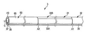
- a single member vibrating portion 63 different from the single member vibrating portion 32 may be provided on the distal direction side of the multiple member vibrating portion 31.
- the single member vibration part 63 is composed of only the integral vibration member 65. With the ultrasonic vibration transmitted, the integral vibration member 65 vibrates in the same vibration mode as the coupled vibration members 33A and 33B.
- the single member vibrating portion 63 is directly connected to the distal direction side of the multiple member vibrating portion 31 at the second antinode position A2. Further, the tip of the single member vibrating portion 63 becomes the tip of the ultrasonic probe 3, and becomes the third antinode vibration A3 of the ultrasonic vibration on the tip direction side from the second antinode position A2.
- the state changes from the state in which the plurality of coupled vibration members 33A and 33B vibrate at the second antinode position A2 to the state in which the single integrated vibration member 65 vibrates. That is, the number of members that vibrate at the second antinode position A2 is set to change.
- the vibration mode does not change due to a change in the number of vibrating members, and the ultrasonic probe 3 appropriately performs longitudinal vibration. Thereby, the ultrasonic vibration is appropriately transmitted to the distal treatment section 30 of the ultrasonic probe 3.
- the two connecting vibration members 33A and 33B are provided in the plural member vibration portion 31, but the present invention is not limited to this.
- the multi-member vibration section 31 may include three coupled vibration members 33A to 33C.
- the coupled vibration members 33A to 33C are coupled to each other, and the respective coupled vibration members 33A to 33C are along the longitudinal axis C between the first antinode position A1 and the second antinode position A2. It is extended. Then, in a state where the ultrasonic vibration is transmitted, the coupled vibration member 33A vibrates in the same vibration mode as the other coupled vibration members 33B and 33C.
- the grooves 53A to 53C corresponding to the coupling vibration members 33A to 33C are defined by the groove defining portion 55, respectively.
- the groove 53A of the coupled vibration member 33A forms part of the passage 37 inside the multi-member vibration section 31 in cooperation with the grooves 53B and 53C of the other coupled vibration members 33B and 33C.
- the passage 37 of the ultrasonic probe 3 is used as a suction path through which the liquid to be sucked passes.
- the present invention is not limited to this.
- liquid feeding may be performed near the treatment target via the passage 37.
- the ultrasonic probe 3 is provided with a plurality of coupled vibration members (33A to 33C) coupled to each other, and each between the first antinode position A1 and the second antinode position A2.
- the connected vibration members (33A to 33C) may be provided with a multi-member vibration portion 31 extending along the longitudinal axis C. Then, each of the connected vibration members (for example, 33A) may vibrate in the same vibration mode as the other connected vibration members (for example, 33B and 33C) in a state where the ultrasonic vibration is transmitted.
- each connected vibration member for example, 33A
- the groove (for example, 53A) of each connected vibration member cooperates with the groove (for example, 53A, 53B) of the other connected vibration member (for example, 33B, 33C) to At least a part of the passage 37 may be formed.
- the ultrasonic probe 3 can be easily manufactured regardless of the type of passage 37 provided therein. Further, even when there is a portion where the number of vibrating members changes, the ultrasonic vibration can be appropriately transmitted to the distal treatment section 30 of the ultrasonic probe 3.
Landscapes
- Health & Medical Sciences (AREA)
- Life Sciences & Earth Sciences (AREA)
- Engineering & Computer Science (AREA)
- Surgery (AREA)
- Public Health (AREA)
- Animal Behavior & Ethology (AREA)
- General Health & Medical Sciences (AREA)
- Nuclear Medicine, Radiotherapy & Molecular Imaging (AREA)
- Veterinary Medicine (AREA)
- Biomedical Technology (AREA)
- Dentistry (AREA)
- Mechanical Engineering (AREA)
- Heart & Thoracic Surgery (AREA)
- Medical Informatics (AREA)
- Molecular Biology (AREA)
- Surgical Instruments (AREA)
- Radiology & Medical Imaging (AREA)
Abstract
La sonde ultrasonore de l'invention est équipée d'une partie vibration de plusieurs éléments qui est à son tour équipée d'une pluralité d'éléments vibration couplés qui sont couplés entre eux, et dans laquelle chacun des éléments vibration couplés se prolonge selon un axe longitudinale entre une première et une seconde position ventre de vibrations ultrasonores. Ladite sonde ultrasonore est en outre équipée d'une partie spécification de rainure qui spécifie des rainures sur chacun desdits éléments vibration couplés, et qui spécifie lesdites rainures dans un état dans lequel au moins une partie d'un trajet est formée dans la partie interne de ladite partie vibration de plusieurs éléments, chacune desdites rainures s'associant à celles des autres éléments vibration couplés.
Priority Applications (4)
| Application Number | Priority Date | Filing Date | Title |
|---|---|---|---|
| JP2013555111A JP5485481B1 (ja) | 2012-06-01 | 2013-05-27 | 超音波プローブ |
| EP13797699.9A EP2856960A4 (fr) | 2012-06-01 | 2013-05-27 | Sonde ultrasonore |
| CN201380003548.5A CN103889357B (zh) | 2012-06-01 | 2013-05-27 | 超声波探头 |
| US14/132,316 US9186526B2 (en) | 2012-06-01 | 2013-12-18 | Ultrasonic treatment probe |
Applications Claiming Priority (2)
| Application Number | Priority Date | Filing Date | Title |
|---|---|---|---|
| US201261654409P | 2012-06-01 | 2012-06-01 | |
| US61/654,409 | 2012-06-01 |
Related Child Applications (1)
| Application Number | Title | Priority Date | Filing Date |
|---|---|---|---|
| US14/132,316 Continuation US9186526B2 (en) | 2012-06-01 | 2013-12-18 | Ultrasonic treatment probe |
Publications (1)
| Publication Number | Publication Date |
|---|---|
| WO2013180055A1 true WO2013180055A1 (fr) | 2013-12-05 |
Family
ID=49673249
Family Applications (1)
| Application Number | Title | Priority Date | Filing Date |
|---|---|---|---|
| PCT/JP2013/064609 Ceased WO2013180055A1 (fr) | 2012-06-01 | 2013-05-27 | Sonde ultrasonore |
Country Status (5)
| Country | Link |
|---|---|
| US (1) | US9186526B2 (fr) |
| EP (1) | EP2856960A4 (fr) |
| JP (1) | JP5485481B1 (fr) |
| CN (1) | CN103889357B (fr) |
| WO (1) | WO2013180055A1 (fr) |
Cited By (1)
| Publication number | Priority date | Publication date | Assignee | Title |
|---|---|---|---|---|
| JP2020526293A (ja) * | 2017-07-07 | 2020-08-31 | エシコン エルエルシーEthicon LLC | 超音波外科用器具の内部からの破片の除去を促進するための機構 |
Families Citing this family (2)
| Publication number | Priority date | Publication date | Assignee | Title |
|---|---|---|---|---|
| EP3448588B1 (fr) * | 2016-04-25 | 2024-04-10 | Les Solutions Médicales Soundbite Inc. | Guide d'ondes mécaniques muni d'un marqueur |
| JP6745347B2 (ja) * | 2016-10-14 | 2020-08-26 | オリンパス株式会社 | 超音波トランスデューサ及び超音波処置システム |
Citations (4)
| Publication number | Priority date | Publication date | Assignee | Title |
|---|---|---|---|---|
| JPH01171537A (ja) * | 1987-12-28 | 1989-07-06 | Sumitomo Bakelite Co Ltd | 外科手術用ハンドピース |
| JPH02123216U (fr) * | 1989-03-20 | 1990-10-09 | ||
| US20050021065A1 (en) | 2003-07-24 | 2005-01-27 | Olympus Corporation | Ultrasonic treatment apparatus |
| JP2007268260A (ja) * | 2006-03-22 | 2007-10-18 | Ethicon Endo Surgery Inc | 超音波手術器具用の複合エンドエフェクター |
Family Cites Families (9)
| Publication number | Priority date | Publication date | Assignee | Title |
|---|---|---|---|---|
| US6309400B2 (en) * | 1998-06-29 | 2001-10-30 | Ethicon Endo-Surgery, Inc. | Curved ultrasonic blade having a trapezoidal cross section |
| US8016843B2 (en) * | 2005-09-09 | 2011-09-13 | Alcon Research Ltd | Ultrasonic knife |
| US9271751B2 (en) * | 2007-05-29 | 2016-03-01 | Ethicon Endo-Surgery, Llc | Ultrasonic surgical system |
| WO2009006291A1 (fr) * | 2007-06-29 | 2009-01-08 | Piezo Resonance Innovations, Inc. | Outil médical permettant de réduire la force de pénétration |
| US8882791B2 (en) * | 2007-07-27 | 2014-11-11 | Ethicon Endo-Surgery, Inc. | Ultrasonic surgical instruments |
| US9107690B2 (en) * | 2007-12-03 | 2015-08-18 | Covidien Ag | Battery-powered hand-held ultrasonic surgical cautery cutting device |
| ES2480422T3 (es) * | 2009-08-14 | 2014-07-28 | Ethicon Endo-Surgery, Inc. | Aparato quirúrgico ultrasónico |
| CN103327920B (zh) * | 2011-03-01 | 2015-12-02 | 奥林巴斯株式会社 | 超声波探头 |
| US9199098B2 (en) * | 2012-09-05 | 2015-12-01 | Olympus Corporation | Ultrasonic treatment device |
-
2013
- 2013-05-27 WO PCT/JP2013/064609 patent/WO2013180055A1/fr not_active Ceased
- 2013-05-27 JP JP2013555111A patent/JP5485481B1/ja not_active Expired - Fee Related
- 2013-05-27 EP EP13797699.9A patent/EP2856960A4/fr not_active Withdrawn
- 2013-05-27 CN CN201380003548.5A patent/CN103889357B/zh active Active
- 2013-12-18 US US14/132,316 patent/US9186526B2/en active Active
Patent Citations (4)
| Publication number | Priority date | Publication date | Assignee | Title |
|---|---|---|---|---|
| JPH01171537A (ja) * | 1987-12-28 | 1989-07-06 | Sumitomo Bakelite Co Ltd | 外科手術用ハンドピース |
| JPH02123216U (fr) * | 1989-03-20 | 1990-10-09 | ||
| US20050021065A1 (en) | 2003-07-24 | 2005-01-27 | Olympus Corporation | Ultrasonic treatment apparatus |
| JP2007268260A (ja) * | 2006-03-22 | 2007-10-18 | Ethicon Endo Surgery Inc | 超音波手術器具用の複合エンドエフェクター |
Non-Patent Citations (1)
| Title |
|---|
| See also references of EP2856960A4 * |
Cited By (2)
| Publication number | Priority date | Publication date | Assignee | Title |
|---|---|---|---|---|
| JP2020526293A (ja) * | 2017-07-07 | 2020-08-31 | エシコン エルエルシーEthicon LLC | 超音波外科用器具の内部からの破片の除去を促進するための機構 |
| JP7171690B2 (ja) | 2017-07-07 | 2022-11-15 | エシコン エルエルシー | 超音波外科用器具の内部からの破片の除去を促進するための機構 |
Also Published As
| Publication number | Publication date |
|---|---|
| US20140188012A1 (en) | 2014-07-03 |
| CN103889357B (zh) | 2016-03-02 |
| JP5485481B1 (ja) | 2014-05-07 |
| CN103889357A (zh) | 2014-06-25 |
| EP2856960A4 (fr) | 2016-01-20 |
| EP2856960A1 (fr) | 2015-04-08 |
| US9186526B2 (en) | 2015-11-17 |
| JPWO2013180055A1 (ja) | 2016-01-21 |
Similar Documents
| Publication | Publication Date | Title |
|---|---|---|
| CN110167467B (zh) | 超声变幅杆 | |
| US9427248B2 (en) | Ultrasonic probe | |
| CN104334103A (zh) | 超声波工作单元以及超声波处理装置 | |
| US9730709B2 (en) | Ultrasonic probe and ultrasonic instrument | |
| JP2008538299A (ja) | 超音波創傷切除プローブとその使用方法 | |
| CN104519816A (zh) | 超声波探头及超声波探头的制造方法 | |
| US9184373B2 (en) | Manufacturing method of an ultrasonic generating device, and manufacturing method of an ultrasonic treatment device | |
| JP5485481B1 (ja) | 超音波プローブ | |
| JP5690452B2 (ja) | 超音波伝達ユニット及び超音波処置装置 | |
| CN103596512B (zh) | 超声波处理装置 | |
| JP5690451B2 (ja) | 超音波伝達ユニット及び超音波処置装置 | |
| US11864777B2 (en) | Ultrasonic system | |
| JP5478764B2 (ja) | 超音波プローブ及び超音波処置装置 | |
| JP5663706B2 (ja) | 超音波プローブ |
Legal Events
| Date | Code | Title | Description |
|---|---|---|---|
| ENP | Entry into the national phase |
Ref document number: 2013555111 Country of ref document: JP Kind code of ref document: A |
|
| 121 | Ep: the epo has been informed by wipo that ep was designated in this application |
Ref document number: 13797699 Country of ref document: EP Kind code of ref document: A1 |
|
| NENP | Non-entry into the national phase |
Ref country code: DE |
|
| WWE | Wipo information: entry into national phase |
Ref document number: 2013797699 Country of ref document: EP |