WO2013181815A1 - Dispositif de conditionnement d'air de caisson éco-énergétique - Google Patents
Dispositif de conditionnement d'air de caisson éco-énergétique Download PDFInfo
- Publication number
- WO2013181815A1 WO2013181815A1 PCT/CN2012/076553 CN2012076553W WO2013181815A1 WO 2013181815 A1 WO2013181815 A1 WO 2013181815A1 CN 2012076553 W CN2012076553 W CN 2012076553W WO 2013181815 A1 WO2013181815 A1 WO 2013181815A1
- Authority
- WO
- WIPO (PCT)
- Prior art keywords
- heat exchange
- energy
- air conditioner
- heat pipe
- cabinet air
- Prior art date
- Legal status (The legal status is an assumption and is not a legal conclusion. Google has not performed a legal analysis and makes no representation as to the accuracy of the status listed.)
- Ceased
Links
Images


Classifications
-
- F—MECHANICAL ENGINEERING; LIGHTING; HEATING; WEAPONS; BLASTING
- F24—HEATING; RANGES; VENTILATING
- F24F—AIR-CONDITIONING; AIR-HUMIDIFICATION; VENTILATION; USE OF AIR CURRENTS FOR SCREENING
- F24F1/00—Room units for air-conditioning, e.g. separate or self-contained units or units receiving primary air from a central station
- F24F1/02—Self-contained room units for air-conditioning, i.e. with all apparatus for treatment installed in a common casing
- F24F1/022—Self-contained room units for air-conditioning, i.e. with all apparatus for treatment installed in a common casing comprising a compressor cycle
-
- F—MECHANICAL ENGINEERING; LIGHTING; HEATING; WEAPONS; BLASTING
- F24—HEATING; RANGES; VENTILATING
- F24F—AIR-CONDITIONING; AIR-HUMIDIFICATION; VENTILATION; USE OF AIR CURRENTS FOR SCREENING
- F24F12/00—Use of energy recovery systems in air conditioning, ventilation or screening
- F24F12/001—Use of energy recovery systems in air conditioning, ventilation or screening with heat-exchange between supplied and exhausted air
- F24F12/002—Use of energy recovery systems in air conditioning, ventilation or screening with heat-exchange between supplied and exhausted air using an intermediate heat-transfer fluid
- F24F2012/005—Use of energy recovery systems in air conditioning, ventilation or screening with heat-exchange between supplied and exhausted air using an intermediate heat-transfer fluid using heat pipes
-
- Y—GENERAL TAGGING OF NEW TECHNOLOGICAL DEVELOPMENTS; GENERAL TAGGING OF CROSS-SECTIONAL TECHNOLOGIES SPANNING OVER SEVERAL SECTIONS OF THE IPC; TECHNICAL SUBJECTS COVERED BY FORMER USPC CROSS-REFERENCE ART COLLECTIONS [XRACs] AND DIGESTS
- Y02—TECHNOLOGIES OR APPLICATIONS FOR MITIGATION OR ADAPTATION AGAINST CLIMATE CHANGE
- Y02B—CLIMATE CHANGE MITIGATION TECHNOLOGIES RELATED TO BUILDINGS, e.g. HOUSING, HOUSE APPLIANCES OR RELATED END-USER APPLICATIONS
- Y02B30/00—Energy efficient heating, ventilation or air conditioning [HVAC]
- Y02B30/56—Heat recovery units
Definitions
- the invention relates to an air conditioner, in particular to a cabinet air conditioner, in particular to an internal heat exchange device, which can select a more reasonable heat transfer mode according to the temperature difference between the air conditioning environment and the atmospheric environment. Therefore, the energy-saving cabinet air conditioner that reduces energy consumption belongs to the technical field of refrigeration equipment.
- the heat of the high temperature side heat generating object is quickly transmitted to the low temperature heat source through the heat pipe, and its heat conduction capacity exceeds the heat conductivity of any known metal. .
- the heat transfer in the heat pipe is carried out through the phase change process of the working fluid.
- the heat pipe heat exchanger composed of the heat pipe has the characteristics of large heat transfer amount, small temperature difference, light weight and small volume, rapid heat response, easy division of the air passage, and high reliability.
- the heat pipe heat exchanger must realize the unidirectional conduction transfer of heat in the presence of temperature difference, so its single application has limitations.
- the object of the present invention is to provide an energy-saving cabinet air conditioner, which has a compact and simple structure, good cooling effect, and energy saving.
- the present invention relates to an energy-saving cabinet air conditioner including a vapor compression refrigeration system, a heat pipe heat exchange system, and an electrical component.
- the vapor compression refrigeration system includes a compressor, an evaporator, and a condenser.
- the heat pipe heat exchange system includes an evaporation end and a condensation end.
- the evaporation end of the heat pipe type heat exchange system is a parallel flow heat exchange structure, a tube band heat exchange structure or a tube sheet heat exchange structure
- the condensation end of the heat pipe type heat exchange system is a parallel flow heat exchange structure, One of the tube-and-tube heat exchange structure or the tube-sheet heat exchange structure.
- the electrical component selects to operate one of the vapor compression refrigeration system and the heat pipe heat exchange system or to perform heat transfer according to the detection of the temperature inside and outside the closed space of the cabinet that needs to be cooled.
- the condenser of the vapor compression refrigeration system and the condensation end of the heat pipe heat exchange system are of the same type of heat exchange structure.
- the condenser of the vapor compression refrigeration system and the condensation end of the heat pipe heat exchange system are different forms of heat exchange structures.
- the evaporator of the vapor compression refrigeration system and the evaporation end of the heat pipe heat exchange system are of the same type of heat exchange structure.
- the evaporator of the vapor compression refrigeration system and the evaporation end of the heat pipe heat exchange system are different forms of heat exchange structures.
- the evaporation ends of the heat pipe type heat exchange system are disposed in parallel adjacent to the evaporator, and the condensation end of the heat pipe type heat exchange system is disposed in parallel with the condenser.
- the evaporation end and the condensation end of the heat pipe type heat exchange system are located inside the evaporator and the condenser, respectively.
- an evaporation auxiliary fan is further included, wherein the evaporation end and the evaporator share the evaporation auxiliary fan.
- a condensing auxiliary fan is further included, wherein the condensing end and the condenser share the condensing auxiliary fan.
- the evaporation end and the condensation end of the heat pipe type heat exchange system are of a split structure.
- the evaporation end and the condensation end of the heat pipe type heat exchange system are of a unitary structure.
- an outer casing and a partition in the outer casing wherein the evaporator of the vapor compression refrigeration system and the evaporation end of the heat pipe heat exchange system are located on one side of the partition, and the vapor compression refrigeration system The condenser end of the condenser and heat pipe heat exchange system is located on the other side of the separator.
- the heat pipe heat exchange system further has a flow dividing device and a current collecting device, wherein the condensation end is connected to the flow dividing device to divert the cooled liquid working medium to the evaporation end, and the evaporation end is connected to the current collecting device to be evaporated.
- the gaseous working medium is input to the condensing end.
- the flow dividing device and the current collecting device are respectively located on opposite sides of the evaporation end/condensation end to achieve sufficient heat exchange.
- the tube-sheet heat exchange structure is composed of a plurality of copper tubes and is formed with a heat exchange circuit of at least two in and two out.
- the invention has the beneficial effects that: by integrating the heat pipe type heat exchange system and the vapor compression type refrigeration system, the two modes are coordinated to realize the heat transfer function, which can save energy and prolong the service life of the compressor and the air conditioner.
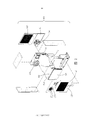
- FIG. 1 is a partially exploded perspective view of an air-saving cabinet air conditioner of the present invention
- FIG. 2 is a partially exploded perspective view showing another angle of the energy-saving cabinet air conditioner of the present invention
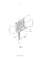
- FIG. 3 is a three-dimensional assembly diagram of a vapor compression refrigeration system and a heat exchange system of the energy-saving cabinet air conditioner of the present invention
- FIG. 4 is a perspective assembled view of another angle of the structure shown in FIG. 3.
- the present invention proposes an energy-saving cabinet air conditioner by integrating a heat pipe type heat exchange system inside a vapor compression refrigeration system.
- the heat pipe is a heat transfer element with high thermal conductivity. It transfers heat by evaporation and condensation of the working medium in the fully enclosed vacuum envelope. It has extremely high thermal conductivity, good isothermality, and heat transfer on both sides of the hot and cold. The area can be arbitrarily changed, long-distance heat transfer, temperature control and other advantages.
- the heat pipe type heat exchange system composed of heat pipes has the advantages of high heat transfer efficiency, small fluid resistance loss, and favorable control of dew point corrosion. Moreover, the heat pipe type heat exchange system does not require a compressor and does not require a Freon working medium, and has a compact structure, a small mass and a small profile.
- the heat pipe works by transferring heat from the evaporation and condensation of the working medium.
- the working medium of the heat pipe is divided into several types of heat pipes such as low temperature, medium temperature and high temperature according to the composition and proportion.
- the more common working mediums are ammonia, water, acetone and methanol.
- the two ends of the heat pipe are respectively an evaporation end (heating end) and a condensation end (heat radiating end), and heat insulation measures are taken between the two ends as needed.
- the evaporation end of the heat pipe is heated, the working fluid in the pipe is vaporized, and the heat of vaporization is absorbed from the heat source. After vaporization, the steam flows to the condensation end of the other side and the condensation heat is released to the heat dissipation zone.
- the condensate is refluxed by the action of capillary force or gravity, and continues to be vaporized by heat, so that the heat in the heat pipe is transmitted through the reciprocating cycle of the phase change process of the working medium, and a large amount of heat is transferred from the heating zone to the heat dissipation zone.
- the heat transfer of the heat pipe type heat exchange system needs to be carried out in the presence of a temperature difference.
- the heat pipe type heat exchange system When integrated in a conventional vapor compression refrigeration system, the heat pipe type heat exchange system is used when the ambient temperature outside the cabinet is low and the operating temperature in the cabinet is high. You can use the temperature difference between the inside and outside of the cabinet to dissipate heat. Therefore, the temperature inside the cabinet can be lowered and the temperature can be adjusted without having to start the compressor.
- the greater the temperature difference the greater the heat dissipation power of the heat pipe heat exchange system. This not only saves energy, but also extends the service life of key components such as cabinet air conditioners, especially compressors.
- the application limitation of the heat pipe heat exchange system lies in the temperature difference between the inside and the outside of the cabinet, and the temperature reduction in the cabinet cannot be effectively controlled. In the hot summer or when the ambient temperature is high, the heat pipe heat exchange system is almost ineffective when the heat is reversely transferred. Therefore, integrating the heat pipe heat exchange system into the existing vapor compression refrigeration system will greatly improve the energy-saving and efficient quality of the cabinet air conditioner.
- the refrigeration system of the cabinet is a vapor compression refrigeration system for temperature control of the cabinet.
- the refrigeration system includes a compressor, an evaporator, a condenser, a throttling element, and an electrical component, and the evaporator and the condenser are respectively equipped with fans and have respective air passages.
- the two systems are used in combination, and the structure size of the heat pipe type heat exchange system can be set according to the amount of heat exchange.
- the control system consisting of electrical components determines whether to start the steam compression refrigeration system or the heat pipe heat exchange system according to factors such as the ambient temperature and the temperature inside the cabinet, or the two systems operate simultaneously. In this way, the cabinet air conditioner can be prevented from starting the compressor or reducing the number of compressor starts when the external working conditions are relatively cold. In the hot summer or when the ambient temperature is high, the compressor is relied on for cooling without starting the heat pipe heat exchange system.
- the energy-saving cabinet air conditioner 100 includes an outer casing having at least a front panel 11 and a rear panel 12, a vapor compression refrigeration system 3 housed in the outer casing, and a heat pipe type.
- the energy-saving cabinet air conditioner 100 of the present invention further includes a partition 5 for dividing the energy-saving cabinet air conditioner 100 into an internal circulation heat exchange system and an external circulation heat exchange system which are isolated from each other.
- the outer panel 11 of the outer casing is respectively provided with an outer air inlet 110 at the lower portion and an outer air outlet 112 at the upper portion.
- the air inlet 120 in the upper part of the cabinet and the air outlet 122 in the lower part are respectively arranged on the rear panel 12 of the outer casing.
- the vapor compression refrigeration system 3 includes a compressor 30 mounted on the bottom plate 13 of the outer casing, an evaporator 32 opposite to the air outlet 122 in the cabinet, an evaporation auxiliary fan 33 opposite to the air inlet 120 in the cabinet, and an air outlet 112 outside the cabinet.
- the opposite condenser 31 and the condensation auxiliary fan 34 opposite to the inlet air inlet 110.
- the heat pipe type heat exchange system 4 includes a condensation end 41 disposed in parallel with the condenser 31 and disposed adjacent to the inside (rear) of the condenser 31, and an evaporation end 42 disposed in parallel with the evaporator 32 and disposed adjacent to the inside (front) of the evaporator 32.
- the condensation end 41 shares the condensation auxiliary fan 34 with the condenser 31, and the evaporation end 42 shares the evaporation auxiliary fan 33 with the evaporator 32.
- the condensation end 41 of the heat pipe heat exchange system 4 is a parallel flow heat exchange structure
- the evaporation end 42 is a tube sheet heat exchange structure.
- the parallel flow heat exchange structure includes an upper header 411 and a lower header 412 which are parallel to each other at the upper and lower ends, and a plurality of parallel and parallel lines between the upper and lower headers 411 and 412
- the flat tube 410 of the fin is composed.
- the upper header 411 has a header inlet 4110 and the lower header 412 has a header outlet 4120.
- the header inlet 4110 and the header outlet 4120 are disposed diagonally opposite to each other (ie, disposed on both sides of the condensation end 41) to increase the flow area of the working medium and enhance the heat exchange effect.
- the parallel flow heat exchange structure has a relatively short working fluid flow, small pressure loss, less heat loss, high heat exchange efficiency, small volume, good anti-vibration effect and light weight.
- the tube-sheet heat exchange structure has a plurality of finned U-shaped copper tubes 420, a flow dividing device 421 connecting the inlets of the respective copper tubes 420, and a unified header outlet 422 connecting the outlets of the respective copper tubes 420.
- the U-shaped copper tube 420 is only one embodiment of the present invention, and it may also be an aluminum tube or other material having better heat exchange performance.
- the flow dividing device 421 is in communication with the header outlet 4120, receives the liquid working medium from the condensation end 41, and the header outlet 422 communicates with the header inlet 4110 of the condensation end 41 to form a current collecting device for operating the vaporized state after evaporation. The medium is fed to the condensation end 41 for heat exchange.
- the working fluid circulates the medium, the copper tube has a large diameter, the working fluid has small resistance, and is easy to evaporate. Moreover, when the working medium flows out from the header outlet 4120 of the condensing end 41 and flows into the U-shaped copper tube 420 of the evaporation end 42 via the flow dividing device 421, the flow path is compared in the flat tube 410 of the original condensing end 41. Narrow, suddenly released into the wider copper tube 420 flow path, the flow will become larger, there will be better heat transfer.
- the copper tube flow path of the present invention is a multi-input and multi-out structure. In the preferred embodiment of the present invention, it is three-in and three-out, and can be released in multiple circuits, and the heat exchange effect is better.
- the condensation end 41 in the present invention is not limited to the parallel flow heat exchange structure, and the tube-sheet heat exchange structure and the tube-and-tube heat exchange structure can realize the function of the condensation end 41.
- the evaporation end 42 in the present invention is not limited to the tube-sheet heat exchange structure, and the parallel flow heat exchange structure and the tube-and-tube heat exchange structure can realize the function of the evaporation end 42.
- the tube-and-belt heat exchange structure includes a plurality of heat-dissipating tubes and a heat-dissipating belt integrated with the heat-dissipating tubes, and may have fins. Because it is a well-known product in the industry, it will not be specifically introduced here.
- the heat exchange structure forms of the condensation end 41 and the evaporation end 42 may be the same or different.
- the condensing end 41 and the evaporating end 42 are also not limited to the split structure, and may be of a unitary structure and separated by the partition 5.
- the condenser 31 of the vapor compression refrigeration system 3 also employs a parallel flow heat exchange structure similar to the condensation end 41, and the evaporator 32 also employs a tube type similar to the evaporation end 42.
- Heat exchange structure This arrangement is advantageous for achieving a more compact layout, however, the condenser 31 is not limited to the parallel flow heat exchange structure, and may be of a tube type or a tube type, and the evaporator 32 is not limited to the tube type.
- the heat exchange structure which can also be of a parallel flow or a tube belt type, can realize the present invention.
- the respective flat tubes of the parallel flow heat exchange structure of the condenser 31 of the vapor compression refrigeration system 3 extend in the horizontal direction, and the parallel flow type of the condensation end 41 of the heat pipe type heat exchange system 4
- Each of the flat tubes 410 of the heat exchange structure extends in a vertical direction, that is, perpendicular to the direction in which the flat tubes of the condenser 31 extend. This arrangement is more advantageous for the airflow direction inside and outside the cabinet, and better heat exchange efficiency is obtained.
- the condenser 31 is disposed in the same direction as the parallel extending direction of the flat tubes of the condensation end 41.
- the control system consisting of the electrical components 2 controls the operation of the vapor compression refrigeration system 3 and the heat pipe heat exchange system 4 according to the actual conditions of the temperature inside the cabinet and the external environment.
- the control system activates the heat pipe type heat exchange system 4 to perform heat transfer transfer.
- the vapor compression refrigeration system 3 may not work or assist in participating in the work to meet the temperature adjustment needs.
- the vapor compression refrigeration system 3 can be directly activated to transfer heat from the low-temperature sealed space (in the cabinet) to the high-temperature external environment for temperature adjustment, thereby saving energy and prolonging compression.
- the technical effect of the overall service life of the machine 30 and the cabinet air conditioner 100 is the technical effect of the overall service life of the machine 30 and the cabinet air conditioner 100.
- the hot air inside the cabinet flows through the air inlet 120, the evaporation auxiliary fan 33, the evaporation end 42 and the evaporation auxiliary fan 33.
- the evaporator 32 sends the air cooled by the evaporation end 42 and/or the evaporator 32 to the cabinet through the air outlet 122 of the cabinet to cool the cabinet.
- the air outside the cabinet under the action of the condensation auxiliary fan 34, enters the condensation auxiliary fan 34, the condensation end 41 and the condenser 31 through the outside air inlet 110, and heats the condenser 31 and/or the condensation end 41 after cooling.
- the condensation end 41 of the heat pipe heat exchange system 4 is a parallel flow heat exchange structure, and the evaporation end 42 is a tube sheet heat exchange structure
- the condensation end since the inside of the heat pipe heat exchange system 4 is a negative pressure, the condensation end
- the internal working medium is cooled to a liquid and then merged to the lower header 412, and flows through the header outlet 4120 to the flow dividing device 421 to be branched to the heat exchange passage inlet of each copper tube 420 and flows into the heat exchange passage.
- the working medium then changes to a gaseous state, and the collector outlet 422 of the evaporation end 42 flows into the header inlet 4110 and then enters the upper header 411 of the evaporation end 41, thus circulating back and forth.
Landscapes
- Engineering & Computer Science (AREA)
- Chemical & Material Sciences (AREA)
- Combustion & Propulsion (AREA)
- Mechanical Engineering (AREA)
- General Engineering & Computer Science (AREA)
- Other Air-Conditioning Systems (AREA)
Priority Applications (1)
| Application Number | Priority Date | Filing Date | Title |
|---|---|---|---|
| PCT/CN2012/076553 WO2013181815A1 (fr) | 2012-06-07 | 2012-06-07 | Dispositif de conditionnement d'air de caisson éco-énergétique |
Applications Claiming Priority (1)
| Application Number | Priority Date | Filing Date | Title |
|---|---|---|---|
| PCT/CN2012/076553 WO2013181815A1 (fr) | 2012-06-07 | 2012-06-07 | Dispositif de conditionnement d'air de caisson éco-énergétique |
Publications (1)
| Publication Number | Publication Date |
|---|---|
| WO2013181815A1 true WO2013181815A1 (fr) | 2013-12-12 |
Family
ID=49711287
Family Applications (1)
| Application Number | Title | Priority Date | Filing Date |
|---|---|---|---|
| PCT/CN2012/076553 Ceased WO2013181815A1 (fr) | 2012-06-07 | 2012-06-07 | Dispositif de conditionnement d'air de caisson éco-énergétique |
Country Status (1)
| Country | Link |
|---|---|
| WO (1) | WO2013181815A1 (fr) |
Cited By (10)
| Publication number | Priority date | Publication date | Assignee | Title |
|---|---|---|---|---|
| CN105258300A (zh) * | 2015-11-10 | 2016-01-20 | 太原重工股份有限公司 | 一种用于挖掘机机棚或电气控制室的温度调节装置 |
| CN108458433A (zh) * | 2018-03-30 | 2018-08-28 | 深圳市艾特网能技术有限公司 | 带辅助冷源的被动式热管自然冷多联制冷系统及其控制方法 |
| CN108668508A (zh) * | 2018-06-08 | 2018-10-16 | 浙江大学山东工业技术研究院 | 机柜的冷却装置及机柜 |
| CN109489126A (zh) * | 2018-11-14 | 2019-03-19 | 深圳市共济科技股份有限公司 | 一种一体式节能空调器及其控制方法 |
| CN110971085A (zh) * | 2019-12-10 | 2020-04-07 | 江苏南通申通机械有限公司 | 一种空冷型相变冷却电机 |
| CN112185913A (zh) * | 2020-08-27 | 2021-01-05 | 珠海格力电器股份有限公司 | 换热基板组件、换热模块、控制器、空调器 |
| CN113473818A (zh) * | 2021-07-30 | 2021-10-01 | 浙江中思能源科技有限公司 | 一种基于通讯基站的换热装置 |
| CN114115391A (zh) * | 2021-10-13 | 2022-03-01 | 郑州德玛电气有限公司 | 一种嵌入式机柜循环温控系统及使用方法 |
| CN117500242A (zh) * | 2023-11-20 | 2024-02-02 | 联达(广东)信息科技股份有限公司 | 一种机柜散热器及其控制方法 |
| CN117515689A (zh) * | 2023-11-09 | 2024-02-06 | 中铁房地产集团设计咨询有限公司 | 建筑节能通风系统 |
Citations (6)
| Publication number | Priority date | Publication date | Assignee | Title |
|---|---|---|---|---|
| US5320167A (en) * | 1992-11-27 | 1994-06-14 | Thermo King Corporation | Air conditioning and refrigeration systems utilizing a cryogen and heat pipes |
| US5695004A (en) * | 1992-07-10 | 1997-12-09 | Beckwith; William R. | Air conditioning waste heat/reheat method and apparatus |
| CN101196325A (zh) * | 2006-12-08 | 2008-06-11 | 苏州昆拓冷机有限公司 | 节能空调器 |
| CN102155769A (zh) * | 2011-03-01 | 2011-08-17 | 合肥天鹅制冷科技有限公司 | 整体式热管复合空调 |
| CN202066134U (zh) * | 2010-12-27 | 2011-12-07 | 张永旺 | 热管式通信基站节能空调 |
| CN102486324A (zh) * | 2010-12-02 | 2012-06-06 | 苏州昆拓热控系统股份有限公司 | 节能机柜空调器 |
-
2012
- 2012-06-07 WO PCT/CN2012/076553 patent/WO2013181815A1/fr not_active Ceased
Patent Citations (6)
| Publication number | Priority date | Publication date | Assignee | Title |
|---|---|---|---|---|
| US5695004A (en) * | 1992-07-10 | 1997-12-09 | Beckwith; William R. | Air conditioning waste heat/reheat method and apparatus |
| US5320167A (en) * | 1992-11-27 | 1994-06-14 | Thermo King Corporation | Air conditioning and refrigeration systems utilizing a cryogen and heat pipes |
| CN101196325A (zh) * | 2006-12-08 | 2008-06-11 | 苏州昆拓冷机有限公司 | 节能空调器 |
| CN102486324A (zh) * | 2010-12-02 | 2012-06-06 | 苏州昆拓热控系统股份有限公司 | 节能机柜空调器 |
| CN202066134U (zh) * | 2010-12-27 | 2011-12-07 | 张永旺 | 热管式通信基站节能空调 |
| CN102155769A (zh) * | 2011-03-01 | 2011-08-17 | 合肥天鹅制冷科技有限公司 | 整体式热管复合空调 |
Cited By (13)
| Publication number | Priority date | Publication date | Assignee | Title |
|---|---|---|---|---|
| CN105258300A (zh) * | 2015-11-10 | 2016-01-20 | 太原重工股份有限公司 | 一种用于挖掘机机棚或电气控制室的温度调节装置 |
| CN108458433A (zh) * | 2018-03-30 | 2018-08-28 | 深圳市艾特网能技术有限公司 | 带辅助冷源的被动式热管自然冷多联制冷系统及其控制方法 |
| CN108458433B (zh) * | 2018-03-30 | 2024-01-30 | 深圳市艾特网能技术有限公司 | 带辅助冷源的被动式热管自然冷多联制冷系统及其控制方法 |
| CN108668508B (zh) * | 2018-06-08 | 2024-03-26 | 浙江大学山东工业技术研究院 | 机柜的冷却装置及机柜 |
| CN108668508A (zh) * | 2018-06-08 | 2018-10-16 | 浙江大学山东工业技术研究院 | 机柜的冷却装置及机柜 |
| CN109489126A (zh) * | 2018-11-14 | 2019-03-19 | 深圳市共济科技股份有限公司 | 一种一体式节能空调器及其控制方法 |
| CN110971085A (zh) * | 2019-12-10 | 2020-04-07 | 江苏南通申通机械有限公司 | 一种空冷型相变冷却电机 |
| CN112185913A (zh) * | 2020-08-27 | 2021-01-05 | 珠海格力电器股份有限公司 | 换热基板组件、换热模块、控制器、空调器 |
| CN112185913B (zh) * | 2020-08-27 | 2025-02-14 | 珠海格力电器股份有限公司 | 换热基板组件、换热模块、控制器、空调器 |
| CN113473818A (zh) * | 2021-07-30 | 2021-10-01 | 浙江中思能源科技有限公司 | 一种基于通讯基站的换热装置 |
| CN114115391A (zh) * | 2021-10-13 | 2022-03-01 | 郑州德玛电气有限公司 | 一种嵌入式机柜循环温控系统及使用方法 |
| CN117515689A (zh) * | 2023-11-09 | 2024-02-06 | 中铁房地产集团设计咨询有限公司 | 建筑节能通风系统 |
| CN117500242A (zh) * | 2023-11-20 | 2024-02-02 | 联达(广东)信息科技股份有限公司 | 一种机柜散热器及其控制方法 |
Similar Documents
| Publication | Publication Date | Title |
|---|---|---|
| WO2013181815A1 (fr) | Dispositif de conditionnement d'air de caisson éco-énergétique | |
| CN214666272U (zh) | 换热器、电控盒以及空调系统 | |
| CN214676259U (zh) | 空调装置以及电控盒 | |
| CN214676255U (zh) | 空调装置以及电控盒 | |
| KR20190080923A (ko) | 온도 조절 가능한 4중 효과 제습 건조 시스템 | |
| CN214676260U (zh) | 空调装置以及电控盒 | |
| CN214666270U (zh) | 换热器、电控盒以及空调系统 | |
| WO2022110745A1 (fr) | Système de dissipation de chaleur, appareil de gestion de chaleur et procédé de fonctionnement associé | |
| CN100516674C (zh) | 节能空调器 | |
| CN214627775U (zh) | 空调装置以及电控盒 | |
| CN212108752U (zh) | 空调室外机 | |
| CN205191965U (zh) | 变频器冷却除湿系统、变频式压缩机组和制冷设备 | |
| CN208238295U (zh) | 一种热管式半导体换热系统 | |
| CN201016498Y (zh) | 节能空调器 | |
| CN203561015U (zh) | 一种多层热管换热式半导体制冷系统 | |
| CN110486853A (zh) | 一种空调外机 | |
| CN216058077U (zh) | 一种基于多联柜通信基站热管理改造系统 | |
| CN209312749U (zh) | 半导体器件散热装置 | |
| CN214627774U (zh) | 空调装置以及电控盒 | |
| CN103557570A (zh) | 一种多层热管换热式半导体制冷系统 | |
| CN100501255C (zh) | 一种电子空气调节器 | |
| CN211204576U (zh) | 基于热管组合制冷系统的模块化冰箱 | |
| CN103476220A (zh) | 节能机柜空调器 | |
| CN223005060U (zh) | 一种空调室外机 | |
| CN115523689A (zh) | 变频空调器及其制冷系统 |
Legal Events
| Date | Code | Title | Description |
|---|---|---|---|
| 121 | Ep: the epo has been informed by wipo that ep was designated in this application |
Ref document number: 12878619 Country of ref document: EP Kind code of ref document: A1 |
|
| NENP | Non-entry into the national phase |
Ref country code: DE |
|
| 122 | Ep: pct application non-entry in european phase |
Ref document number: 12878619 Country of ref document: EP Kind code of ref document: A1 |