WO2013183142A1 - Led前照灯を備える軌条車両 - Google Patents
Led前照灯を備える軌条車両 Download PDFInfo
- Publication number
- WO2013183142A1 WO2013183142A1 PCT/JP2012/064667 JP2012064667W WO2013183142A1 WO 2013183142 A1 WO2013183142 A1 WO 2013183142A1 JP 2012064667 W JP2012064667 W JP 2012064667W WO 2013183142 A1 WO2013183142 A1 WO 2013183142A1
- Authority
- WO
- WIPO (PCT)
- Prior art keywords
- light source
- connection line
- far
- nearby
- spare
- Prior art date
- Legal status (The legal status is an assumption and is not a legal conclusion. Google has not performed a legal analysis and makes no representation as to the accuracy of the status listed.)
- Ceased
Links
Images






Classifications
-
- B—PERFORMING OPERATIONS; TRANSPORTING
- B60—VEHICLES IN GENERAL
- B60Q—ARRANGEMENT OF SIGNALLING OR LIGHTING DEVICES, THE MOUNTING OR SUPPORTING THEREOF OR CIRCUITS THEREFOR, FOR VEHICLES IN GENERAL
- B60Q1/00—Arrangement of optical signalling or lighting devices, the mounting or supporting thereof or circuits therefor
- B60Q1/02—Arrangement of optical signalling or lighting devices, the mounting or supporting thereof or circuits therefor the devices being primarily intended to illuminate the way ahead or to illuminate other areas of way or environments
- B60Q1/04—Arrangement of optical signalling or lighting devices, the mounting or supporting thereof or circuits therefor the devices being primarily intended to illuminate the way ahead or to illuminate other areas of way or environments the devices being headlights
- B60Q1/14—Arrangement of optical signalling or lighting devices, the mounting or supporting thereof or circuits therefor the devices being primarily intended to illuminate the way ahead or to illuminate other areas of way or environments the devices being headlights having dimming means
-
- B—PERFORMING OPERATIONS; TRANSPORTING
- B60—VEHICLES IN GENERAL
- B60Q—ARRANGEMENT OF SIGNALLING OR LIGHTING DEVICES, THE MOUNTING OR SUPPORTING THEREOF OR CIRCUITS THEREFOR, FOR VEHICLES IN GENERAL
- B60Q1/00—Arrangement of optical signalling or lighting devices, the mounting or supporting thereof or circuits therefor
- B60Q1/02—Arrangement of optical signalling or lighting devices, the mounting or supporting thereof or circuits therefor the devices being primarily intended to illuminate the way ahead or to illuminate other areas of way or environments
- B60Q1/04—Arrangement of optical signalling or lighting devices, the mounting or supporting thereof or circuits therefor the devices being primarily intended to illuminate the way ahead or to illuminate other areas of way or environments the devices being headlights
- B60Q1/14—Arrangement of optical signalling or lighting devices, the mounting or supporting thereof or circuits therefor the devices being primarily intended to illuminate the way ahead or to illuminate other areas of way or environments the devices being headlights having dimming means
- B60Q1/1415—Dimming circuits
-
- B—PERFORMING OPERATIONS; TRANSPORTING
- B60—VEHICLES IN GENERAL
- B60Q—ARRANGEMENT OF SIGNALLING OR LIGHTING DEVICES, THE MOUNTING OR SUPPORTING THEREOF OR CIRCUITS THEREFOR, FOR VEHICLES IN GENERAL
- B60Q1/00—Arrangement of optical signalling or lighting devices, the mounting or supporting thereof or circuits therefor
- B60Q1/02—Arrangement of optical signalling or lighting devices, the mounting or supporting thereof or circuits therefor the devices being primarily intended to illuminate the way ahead or to illuminate other areas of way or environments
- B60Q1/04—Arrangement of optical signalling or lighting devices, the mounting or supporting thereof or circuits therefor the devices being primarily intended to illuminate the way ahead or to illuminate other areas of way or environments the devices being headlights
- B60Q1/06—Arrangement of optical signalling or lighting devices, the mounting or supporting thereof or circuits therefor the devices being primarily intended to illuminate the way ahead or to illuminate other areas of way or environments the devices being headlights adjustable, e.g. remotely-controlled from inside vehicle
-
- B—PERFORMING OPERATIONS; TRANSPORTING
- B60—VEHICLES IN GENERAL
- B60Q—ARRANGEMENT OF SIGNALLING OR LIGHTING DEVICES, THE MOUNTING OR SUPPORTING THEREOF OR CIRCUITS THEREFOR, FOR VEHICLES IN GENERAL
- B60Q11/00—Arrangement of monitoring devices for devices provided for in groups B60Q1/00 - B60Q9/00
- B60Q11/002—Emergency driving lights in the event of failure of the principal lighting circuit
-
- B—PERFORMING OPERATIONS; TRANSPORTING
- B61—RAILWAYS
- B61D—BODY DETAILS OR KINDS OF RAILWAY VEHICLES
- B61D29/00—Lighting
-
- B—PERFORMING OPERATIONS; TRANSPORTING
- B61—RAILWAYS
- B61L—GUIDING RAILWAY TRAFFIC; ENSURING THE SAFETY OF RAILWAY TRAFFIC
- B61L15/00—Indicators provided on the vehicle or train for signalling purposes
- B61L15/02—Head or tail indicators, e.g. light
-
- B—PERFORMING OPERATIONS; TRANSPORTING
- B61—RAILWAYS
- B61L—GUIDING RAILWAY TRAFFIC; ENSURING THE SAFETY OF RAILWAY TRAFFIC
- B61L2207/00—Features of light signals
- B61L2207/02—Features of light signals using light-emitting diodes [LEDs]
Definitions
- the present invention relates to a rail vehicle, and in particular, can illuminate a wide range from the front of the traveling direction to a distance, and can switch between the amount of light emitted from a plurality of light sources and the irradiation direction (optical axis).
- the present invention relates to a rail vehicle including an LED headlamp having a function of complementing a function lost by another light source when a part of the light source constituting the headlamp is lost.
- train signs are provided at the front and rear portions of the rail vehicle.
- the train sign provided at the foremost portion facing the traveling direction is a headlamp composed of an incandescent lamp and a high-pressure discharge lamp, and the train sign provided at the rearmost portion is a tail lamp composed of a red light.
- the headlamps provided on the rail vehicle are selectively lit with a plurality of light sources having a function of changing the optical axis or having different optical axes.
- Patent Document 1 discloses an illumination control device including a plurality of light sources having different optical axes, and when any one of the light sources fails, the failure is detected and failed. A technique for forcibly lighting another light source as an alternative to the light source is disclosed.
- LEDs light emitting diodes
- a headlamp provided in a rail vehicle
- light emitted from the LED element has a strong linearity and a property that does not easily diffuse compared to that of an incandescent lamp or a high-pressure discharge lamp.
- a scene that promotes a feeling or a scene in which only a far distance in the traveling direction or only the front is illuminated and a wide range from the near to the far is not illuminated.
- the driving operation for suppressing dazzling after any one of the light sources fails is not a complicated operation.
- the purpose of the present invention is to illuminate a wide range far from the front, and to provide a dimming function that changes the optical axis and reduces the overall light quantity to suppress the dazzling feeling, when one of the light sources fails.
- a rail vehicle with LED headlamps that has the reliability that can replace other light sources as a replacement for a failed light source and the operability that reduces the dazzling feeling after any one of the light sources fails It is to be.
- a rail vehicle provided with the LED headlamp of the present invention includes, as basic means, a plurality of distant light sources that illuminate distant, a plurality of near light sources that illuminate the vicinity, the distant light source and the vicinity.
- An LED headlamp composed of a power source for supplying power to the light source, and having one light source group composed of the far light source and the near light source, and the other light source group composed only of the near light source.
- the one light source group or the other light source group is selectively turned on.
- the one light source group is a first far light source, a second far light source, and a first near light source
- the other light source group is a second near light source, and supplies power to the first near light source.
- a switch provided on the line, and a current detection device that detects a current of the second nearby light source, and controls the switch according to an output of the current detection device.
- the present invention illuminates a wide range from the near side to the far side, and has a dimming function for changing the optical axis and reducing the total light amount in order to suppress dazzling feeling, when one of the light sources breaks down
- a rail vehicle equipped with LED headlamps that have reliability that can replace other light sources in place of the failed light source, and operability that reduces the dazzling feeling after any one of the light sources fails can do.
- FIG. 1 is a front view showing an example of a headlamp provided in a railway vehicle.
- FIG. 2 is a front view illustrating the headlamp according to the first embodiment.
- 3 is a cross-sectional view taken along the line AA of the headlamp (Example 1) shown in FIG.
- FIG. 4 is a circuit diagram of the headlamp (Example 1) shown in FIG.
- FIG. 5 is a front view of the headlamp according to the second embodiment.
- FIG. 6 is a cross-sectional view of the headlamp (Example 2) taken along the line BB in FIG.
- FIG. 7 is a front view of the headlamp according to the third embodiment.
- FIG. 8 is a perspective view of a headlamp according to a fourth embodiment.
- FIG. 9 is a perspective view of the headlamp according to the fifth embodiment.
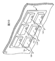
- FIG. 10 is a perspective view of the headlamp according to the sixth embodiment.
- FIG. 11 is a circuit diagram of a headlamp according to the sixth embodiment.
- the present invention relates to a headlamp provided in a rail vehicle that travels along a laid rail.
- Rail vehicles include railcars, streetcars, monorail vehicles, new transportation system vehicles, and the like. In the embodiments described below, railcars will be described as examples of rail vehicles.
- FIG. 1 is a front view showing an example of a headlamp provided in the railway vehicle 10.
- a crew room where a driver is in charge is provided, and windows, wipers, through doors, and the like are provided.
- various facilities such as a platform, a branching device, a railroad crossing, a signal, and a power feeding facility are provided for passengers to get on and off, and staff members are working in these facilities.
- the front lamp 1 is provided as a front sign and the tail lamp 2 is provided as a rear sign on the front of the foremost part and the rearmost part of the railway car 10 so that these staff members can easily recognize the approach and distance of the railway car 10.
- the headlamp 1 and the tail lamp 2 are provided with a light quantity that can recognize the presence of the railway vehicle from a distance. If it is good. Since the headlight 1 and the taillight 1 must be turned on at night or when traveling through a long tunnel, the headlamp 1 or the taillight 2 may be suspended if a failure occurs.
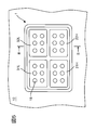
- FIG. 2 is a front view showing the headlamp of the first embodiment
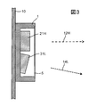
- FIG. 3 is a cross-sectional view taken along the line AA of the headlamp shown in FIG.
- the headlamp 1 includes a first far light source 21H and a second far light source 22H that include an optical axis 12H that illuminates a distance in the traveling direction of the railway vehicle 10, and an optical axis 14L that illuminates the vicinity (front) of the railway vehicle 10 in the traveling direction. And a cover 5 (see FIG. 3) that covers these light sources.
- First distant light source 21H and a second distant sources 22H first near the light source 31L and the second near the light source 32L, a plurality of LED that emits light when a voltage is applied in the forward direction (light-emitting diode, L ight E mitting D iode) It is composed of the element 18.
- FIG. 4 is a circuit diagram of the headlamp (Example 1) shown in FIG.
- Each light source of the first far light source 21H and the second far light source 22H, and the first near light source 31L and the second near light source 32L has a plurality of LED elements 18 connected in series. 21H, 22H, 31L, and 32L are connected to the power supply 15 in parallel.
- a crew member (especially a driver) is provided with a far optical axis 12H and a near optical axis 14L emitted from the headlamp 1 in order to prevent a driver of an oncoming vehicle or a home attendant from being dazzled.
- a change-over switch 11 for arbitrarily switching between lighting of one light source group and lighting of the other light source group consisting of only the adjacent optical axis 14L.
- the change-over switch 11 includes one contact group including a contact 51H, a contact 52H, and a contact 61L for turning on and off each light source of the first far light source 21H, the second far light source 22H, and the first near light source 31L constituting one light source group. , And a contact 62L which is the other contact group for turning on and off the second nearby light source 32L forming the other light source group.
- the light radiated from the LED element 18 has a feature that it is highly straight and difficult to diffuse. For this reason, the first far light source 21H and the second far light source 22H that have the optical axis 12H and illuminate far away, the first near light source 31L that has the optical axis 14L and illuminate the vicinity, and the second far light source 32L.
- a circuit for selectively lighting these is configured separately, only the far side in the traveling direction is illuminated, and the front (near) in the traveling direction is not illuminated, but the near (near) in the traveling direction of the railway vehicle 10. There is a concern that inconveniences such as difficulty in grasping jumping out of the camera may occur.
- the first far light source 21H, the second far light source 22H, and the first near light source 31L are set as one light source group, the second near light source 32L is set as the other light source group, and one light source A circuit capable of selectively lighting the group and the other light source group is configured.
- the changeover switch 11 when the railway vehicle 10 travels between stations without an oncoming vehicle, the changeover switch 11 is operated to close one contact group, and the first far light source 21H, the second far light source 22H, Since the first vicinity light source 31L can be energized to illuminate a wide area from the vicinity of the traveling direction of the railway vehicle 10 to the distance, the crew can travel in a wide range from immediately before (in front of) the railway vehicle 10 to the distance. Obstacles that occur can be easily recognized.
- the contact switch 11 is operated to open one contact group (contact 51H, contact 52H, contact 61L) and the other contact 62L.
- the contact switch 11 By closing only the second vicinity light source 32L and illuminating only the vicinity of the traveling direction of the railway vehicle 10, it is possible to prevent the oncoming vehicle and station staff from feeling dazzled.
- the total light amount of the other light source that illuminates only the vicinity can be made smaller than the total light amount of the one light source that illuminates the vicinity and the distant place, Suppression can be promoted.
- any one of the plurality of distant light sources or a plurality of near light sources is included. Even if a malfunction occurs in any of the above, since the continuous light emission from a distant or nearby light source that maintains soundness can be suppressed and the predetermined function can be maintained, the operation of the railway vehicle 10 is continued. be able to.
- a connection line for supplying power to the first nearby light source 31L included in one light source group and a connection line for supplying power to the second nearby light source 32L of the other light source group are contacts (switches) 82L. Are connected via a backflow prevention diode 19.
- a connection line that supplies power to the second nearby light source 32L is provided with a current detection device 42L that monitors the current flowing through the connection line, and monitors the soundness of the second nearby light source 32L.
- the current flowing through the connection line that supplies power to the second vicinity light source 32L decreases.
- the current detection device 42L detects that a problem has occurred in the second nearby light source 32L from the decrease in current.
- the current detection device 42L that detects the malfunction operates the backup switch 102 to close the switch 82L that is normally open.
- the backup switch 102 may be handled manually after the crew member confirms the output of the current detection device 42L, or may be turned on automatically without the crew member's operation.
- the backup switch 102 After the backup switch 102 is turned on, when the crew member (especially the driver) handles the changeover switch 11 and closes the contact 62L to illuminate only the vicinity of the traveling direction of the railway vehicle 10, the contact 62L is opened and closed from the power supply 15. Power is supplied only to the first near light source 31L (one light source) via the detector 82L and the backflow prevention diode 19, and only the first near light source 31L is lit. In other words, the backup switch 102 turns on the first near light source 31L instead of the second near light source 32L that has been turned off, so that the vicinity of the traveling direction of the railway vehicle 10 can be illuminated.
- the first near light source 31L one light source
- the backup switch 102 After the backup switch 102 is turned on, when the changeover switch 11 is handled and the contacts 51H, 52H, and 61H are closed, the first far light source 21H, the second far light source 22H, and the first near light source 31L (one group) Can be illuminated to illuminate a wide range from the vicinity of the traveling direction of the railway vehicle 10 to the distant place.
- the handling of the changeover switch 11 after the backup switch 102 is turned on is no different from the handling before the backup switch 102 is turned on, and the driver moves from the vicinity to the distance by handling the conventional changeover switch 11.
- the irradiation of the range and the irradiation of only the vicinity can be switched, and the operation for suppressing the dazzling does not become complicated.
- the backflow prevention diode 19 prevents unnecessary lighting by suppressing current from flowing from the contact 61L to the second nearby light source 32L via the switch 82L when the backup switch 102 is accidentally turned on. .
- FIG. 5 is a front view of the headlamp of the second embodiment
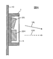
- FIG. 6 is a cross-sectional view taken along the line BB of the headlamp of the second embodiment (second embodiment).
- the first far light source 21H and the second far light source 22H are arranged in the lower stage
- the first neighboring light source 31L and the second neighboring light source 32L are arranged in the upper stage.
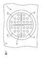
- FIG. 7 is a front view of the headlamp of the third embodiment. 2 and 5, the rectangular headlamp 1 is provided.
- the shape of the headlamp 1 is changed from a rectangle to a circle.
- the circular headlamp 1 is divided into four equal parts in the vertical and horizontal directions with respect to the center of the circular shape, and the first far light source 21H and the second far light source 22H are arranged in the upper stage, and the lower stage.
- the first vicinity light source 31L and the second vicinity light source 32L are provided.
- FIG. 8 is a perspective view of the headlamp of the fourth embodiment
- FIG. 9 is a perspective view of the headlamp of the fifth embodiment.
- the headlamp 1 shown in FIG. 8 has a first far light source 21H, a second far light source 22H, a first near light source 31L, and a first near light source 32L arranged alternately in the horizontal direction.
- the illustrated headlamp 1 is one in which these light sources are alternately arranged in the vertical direction.
- each light source constituting the headlamp 1 shown in FIGS. 5 to 9 shown in FIGS. 5 to 9 are degrees of freedom when designing the front surface (wife face) of the leading vehicle of the railway vehicle 1. It is an example for enhancing The headlamps 1 (Embodiment 2 to Embodiment 5) shown in FIGS. 5 to 9 are provided with the circuit diagram shown in FIG. 4, and thus the effects shown in Embodiment 1, that is, the far light source and the near light source.
- the circuit configuration that can turn on and off at the same time compensates for the characteristics of the LED's strong straightness and difficulty in diffusing, and the effect that the driver can check a wide range from the front to the far side of the traveling direction, and the optical axis that illuminates only the far, near and near And a switch that switches between the total amount of light and the effect of suppressing glare of station staff and oncoming train drivers, and a device that detects a failure of the light source and handles the backup switch based on the output of this failure detection device By replacing the failed light source with a healthy light source, and providing multiple distant light sources and multiple nearby light sources and connecting them in parallel to the power supply It is possible to achieve the effect of improving the reliability of the square and near the light source.
- FIG. 10 is a perspective view of the headlamp of the sixth embodiment
- FIG. 11 is a circuit diagram of the headlamp of the sixth embodiment.
- the headlamp 1 shown in FIG. 10 is disposed in the upper stage in the horizontal direction and has three adjacent light sources 31L, 32L, and 33L having the optical axis 14L, and in the lower stage in the horizontal direction and the optical axis. And three remote light sources 21H, 22H, and 23H having 12H.
- Each of the first near light source 31L, the second near light source 32L, and the third near light source 33L, and the first far light source 21H, the second far light source 22H, and the third far light source 23H includes a plurality of light sources connected in series.
- Each of the light sources 21H, 22H, 23H, 31L, 32L, and 33L forms a parallel circuit in which the voltage of the power supply 15 acts equally.
- the second near light source 32L and the second far light source 22H are spare light sources that are used when a malfunction occurs in another light source.
- a connection line for supplying power to the spare second vicinity light source 32L via the backflow prevention diode 19 and the contact 81L from a connection line for supplying power to the first vicinity light source 31L, and a connection for supplying power to the third vicinity light source 33L A connection line for supplying power from the line to the spare second near light source 32L via the backflow prevention diode 19 and the contact 83L is wired.
- connection line that supplies power from the connection line that supplies power to the first far light source 21H to the spare second far light source 22H via the backflow prevention diode 19 and the contact 72H, and power to the third far light source 23H.
- a connection line for supplying power from the connection line to be supplied to the spare second far light source 22H via the backflow prevention diode 19 and the contact 71H is wired.
- Each connection line that supplies power to each light source of the first vicinity light source 31L and the third vicinity light source 33L includes current detection devices 41L and 43L that monitor the current flowing through each connection line. Health is monitored.
- each connection line that supplies power to each light source of the first far light source 21H and the third far light source 23H includes current detection devices 41H and 43H that monitor the current flowing through each connection line. The health of the light source is monitored.
- the change-over switch 11 includes one contact group including a contact 51H, a contact 53H, and a contact 61L for turning on and off each of the first far light source 21H, the third far light source 23H, and the first neighboring light source 31L, and the second neighboring light source 32L. And a contact 63L which is the other contact group to be turned on and off. That is, the first far light source 21H and the third far light source 23H, and the first near light source 31L are used as one light source group, the third near light source 33L is used as the other light source group, and the one light source group and the other light source group are used. And a circuit that can selectively light up
- the changeover switch 11 when the railway vehicle 10 travels between stations without an oncoming vehicle, the changeover switch 11 is operated to close one contact group, and the first far light source 21H, the third far light source 23H, Since the first vicinity light source 31L can be energized to illuminate a wide area from the vicinity of the traveling direction of the railway vehicle 10 to the distance, the crew can travel in a wide range from immediately before (in front of) the railway vehicle 10 to the distance. Obstacles that occur can be easily recognized.
- the contact switch 11 is operated to open one contact group (contact 51H, contact 53H, contact 61L) and the other contact 63L.
- the contact switch 11 By turning on only the third vicinity light source 33L and illuminating only the vicinity of the traveling direction of the railway vehicle 10, it is possible to suppress the oncoming vehicle and station staff from feeling dazzled.
- the total light amount of the other light source that illuminates only the vicinity can be made smaller than the total light amount of the one light source that illuminates the vicinity and the distant place, Suppression can be promoted.
- any one of the plurality of distant light sources or a plurality of near light sources is included. Even if a malfunction occurs in any of the above, since the continuous light emission from a distant or nearby light source that maintains soundness can be suppressed and the predetermined function can be maintained, the operation of the railway vehicle 10 is continued. be able to.
- the current flowing through the connection line that supplies power to the first near light source 31L is reduced.
- the current detection device 41L detects that a failure has occurred in the first nearby light source 31L from the decrease in current. Based on the output of the current detection device 41L that has detected the malfunction, the backup switch 101 is operated to close the switch 81L that is normally open.
- the current detection device 43L detects this failure, operates the backup switch 103, and closes the switch 83L that is normally open.
- the current detection device 41H detects this failure, operates the backup switch 91, and closes the switch 72H that is normally open.
- the current detection device 43H detects this failure, operates the backup switch 93, and closes the switch 71H that is normally open.
- Each backup switch 91, 93, 101, 103 may be handled after the crew member confirms the output of the current detection devices 41L, 43L, 41H, 43H, or may be automatically turned on without the crew member's operation. .
- the headlamp 1 of the sixth embodiment shown in FIGS. 10 and 11 is replaced with a nearby light source in which a failure occurs when one or both of the first or third nearby light sources 31L and 33L have a failure.
- the spare second light source 32L is replaced with a spare second light source. 2
- a circuit that can turn on the remote light source 22H is configured.
- a crew member handles the changeover switch 11 to open the contact 63L and close the contacts 51H, 53H, and 61L to illuminate a wide range from the vicinity of the traveling direction of the railway vehicle 10 to the distance.
- the third near light source 33L is turned off, and the first near light source 31L, the first far light source 21H, and the spare second far light source 22H are turned on, and a wide range from near to far can be illuminated.
- the handling of the change-over switch 11 after the backup switch 93 is turned on is no different from the handling before the backup switch 93 is turned on, and the driver moves from the vicinity to the distance by handling the conventional change-over switch 11. It is possible to switch between irradiation of the range and irradiation of only the vicinity (optical axis switching), and the operation for suppressing dazzling does not become complicated.
- the above description is a case where the backup switch 93 is handled due to a failure in the third far light source 23H, but when a failure occurs in the first far light source 21H, the first and third neighboring light sources 31L, 33L.
- the contacts (72H, 81L, 83L) corresponding to the respective light sources (21H, 31L, 33L) in which the backup switches 91, 101, 103 corresponding to the respective light sources are handled and the trouble occurs are closed, Since a circuit capable of turning on an alternative light source is configured, description thereof will be omitted.
- the backflow prevention diode 19 provided in the sixth embodiment prevents unnecessary lighting of each light source corresponding to each backup switch when the backup switches 91, 93, 101, and 103 are erroneously turned on. Is provided.
- each spare light is provided in one light source group and the other light source group, higher reliability can be obtained, so that suspension due to a malfunction of the headlamp 1 can be suppressed.
Landscapes
- Engineering & Computer Science (AREA)
- Mechanical Engineering (AREA)
- Lighting Device Outwards From Vehicle And Optical Signal (AREA)
Description
4…光源 5…カバー
10…鉄道車両 11…切り替えSW(H-L)
12H…遠方光軸 14L…近傍光軸
15…電源 16…光源
18…LED素子 19…逆流防止ダイオード
21H…第1遠方光源 22H…第2遠方光源
23H…第3遠方光源 31L…第1近傍光源
32L…第2近傍光源 33L…第3近傍光源
41H…電流検知装置 42H…電流検知装置
43H…電流検知装置 41L…電流検知装置
42L…電流検知装置 43L…電流検知装置
51H~53H…接点 61L~63L…接点
71H~73H…開閉器 81L~83L…接点
91…バックアップスイッチ 93…バックアップスイッチ
101…バックアップスイッチ 103…バックアップスイッチ
Claims (6)
- 遠方を照らす複数の遠方光源と、
近傍を照らす複数の近傍光源と、
前記遠方光源および前記近傍光源に電力を供給する電源と
から構成されるLED前照灯を備える軌条車両において、
前記遠方光源と前記近傍光源とからなる一方の光源群と、
前記近傍光源のみからなる他方の光源群と、を有しており、
前記一方の光源群または前記他方の光源群と、を選択的に点灯すること
を特徴とするLED前照灯を備える軌条車両。 - 請求項1に記される軌条車両において、
前記遠方光源および前記近傍光源は前記電源に並列に接続されること
を特徴とするLED前照灯を備える軌条車両。 - 請求項1に記される軌条車両において、
前記遠方光源および前記近傍光源は直列に接続される複数のLED素子であること
を特徴とするLED前照灯を備える軌条車両。 - 請求項1に記される軌条車両において、
前記一方の光源群は、第1遠方光源と第2遠方光源と第1近傍光源であり、
前記他方の光源群は、第2近傍光源であること
を特徴とするLED前照灯を備える軌条車両。 - 請求項4に記される軌条車両において、
前記第1近傍光源に電力を供給する第1近傍光源接続線と、
前記第2近傍光源に電力を供給する第2近傍光源接続線と、
前記第1近傍光源接続線と前記第2近傍光源接続線とを接続する接続線と
前記接続線に備えられる開閉器と、
前記第2近傍光源の電流を検知する電流検知装置と、
を備えており、
前記電流検知装置の出力に応じて前記開閉器を制御すること
を特徴とするLED前照灯を備える軌条車両。 - 請求項4に記される軌条車両において、
前記第1遠方光源と前記第2遠方光源を代替する予備遠方光源と、
前記第1近傍光源と前記第2近傍光源を代替する予備近傍光源と、
前記第1遠方光源に電力を供給する第1遠方光源接続線と、
前記第2遠方光源に電力を供給する第2遠方光源接続線と、
前記第1近傍光源に電力を供給する第1近傍光源接続線と、
前記第2近傍光源に電力を供給する第2近傍光源接続線と、
前記予備遠方光源に電力を供給する予備遠方光源接続線と、
前記予備近傍光源に電力を供給する予備近傍光源接続線と、
前記第1遠方光源接続線と前記予備遠方光源接続線とを接続する第1遠方光源予備接続線と、
前記第2遠方光源接続線と前記予備遠方光源接続線とを接続する第2遠方光源予備接続線と、
前記第1近傍光源接続線と前記予備近傍光源接続線とを接続する第1近傍光源予備接続線と、
前記第2近傍光源接続線と前記予備近傍光源接続線とを接続する第2近傍光源予備接続線と、
前記第1遠方光源予備接続線と、前記第2遠方光源予備接続線と、前記第1近傍光源予備接続線と、前記第2近傍光源予備接続線と、に備えられる各開閉器と、
前記第1遠方光源接続線と、前記第2遠方光源接続線と、前記第1近傍光源接続線と、前記第2近傍光源接続線と、に備えられる各電流検知装置と、を備えており、
前記各電流検知装置の出力に応じて、前記各開閉器を制御して前記予備遠方光源と前記予備近傍光源とを点灯すること
を特徴とするLED前照灯を備える軌条車両。
Priority Applications (3)
| Application Number | Priority Date | Filing Date | Title |
|---|---|---|---|
| JP2014519762A JP5951766B2 (ja) | 2012-06-07 | 2012-06-07 | Led前照灯を備える軌条車両 |
| PCT/JP2012/064667 WO2013183142A1 (ja) | 2012-06-07 | 2012-06-07 | Led前照灯を備える軌条車両 |
| GB1420638.7A GB2517332B (en) | 2012-06-07 | 2012-06-07 | Rail vehicle equipped with LED headlight |
Applications Claiming Priority (1)
| Application Number | Priority Date | Filing Date | Title |
|---|---|---|---|
| PCT/JP2012/064667 WO2013183142A1 (ja) | 2012-06-07 | 2012-06-07 | Led前照灯を備える軌条車両 |
Publications (1)
| Publication Number | Publication Date |
|---|---|
| WO2013183142A1 true WO2013183142A1 (ja) | 2013-12-12 |
Family
ID=49711559
Family Applications (1)
| Application Number | Title | Priority Date | Filing Date |
|---|---|---|---|
| PCT/JP2012/064667 Ceased WO2013183142A1 (ja) | 2012-06-07 | 2012-06-07 | Led前照灯を備える軌条車両 |
Country Status (3)
| Country | Link |
|---|---|
| JP (1) | JP5951766B2 (ja) |
| GB (1) | GB2517332B (ja) |
| WO (1) | WO2013183142A1 (ja) |
Cited By (3)
| Publication number | Priority date | Publication date | Assignee | Title |
|---|---|---|---|---|
| CN104527729A (zh) * | 2014-12-26 | 2015-04-22 | 成都市新筑路桥机械股份有限公司 | 有轨电车信号灯系统 |
| CN108058638A (zh) * | 2017-12-25 | 2018-05-22 | 马瑞利汽车零部件(芜湖)有限公司 | 自适应远光控制系统 |
| CN111907356A (zh) * | 2020-08-11 | 2020-11-10 | 中车株洲电力机车有限公司 | 一种有轨电车线路供电系统 |
Families Citing this family (1)
| Publication number | Priority date | Publication date | Assignee | Title |
|---|---|---|---|---|
| CA3009600C (en) | 2015-12-22 | 2023-01-03 | Sanjeev KHOSLA | Improved led light systems and device for locomotives and narrow beam and multi beam applications |
Citations (3)
| Publication number | Priority date | Publication date | Assignee | Title |
|---|---|---|---|---|
| JPH04292231A (ja) * | 1991-03-20 | 1992-10-16 | Matsushita Electric Works Ltd | 照明制御装置 |
| JP2001023417A (ja) * | 1999-07-12 | 2001-01-26 | Koito Mfg Co Ltd | 鉄道車両用前照灯 |
| JP2010097829A (ja) * | 2008-10-16 | 2010-04-30 | Stanley Electric Co Ltd | 照明装置および車両用灯具 |
Family Cites Families (2)
| Publication number | Priority date | Publication date | Assignee | Title |
|---|---|---|---|---|
| JPH0419335U (ja) * | 1990-06-07 | 1992-02-18 | ||
| JP4812543B2 (ja) * | 2006-06-28 | 2011-11-09 | 株式会社小糸製作所 | 車両用灯具 |
-
2012
- 2012-06-07 JP JP2014519762A patent/JP5951766B2/ja active Active
- 2012-06-07 GB GB1420638.7A patent/GB2517332B/en not_active Expired - Fee Related
- 2012-06-07 WO PCT/JP2012/064667 patent/WO2013183142A1/ja not_active Ceased
Patent Citations (3)
| Publication number | Priority date | Publication date | Assignee | Title |
|---|---|---|---|---|
| JPH04292231A (ja) * | 1991-03-20 | 1992-10-16 | Matsushita Electric Works Ltd | 照明制御装置 |
| JP2001023417A (ja) * | 1999-07-12 | 2001-01-26 | Koito Mfg Co Ltd | 鉄道車両用前照灯 |
| JP2010097829A (ja) * | 2008-10-16 | 2010-04-30 | Stanley Electric Co Ltd | 照明装置および車両用灯具 |
Cited By (4)
| Publication number | Priority date | Publication date | Assignee | Title |
|---|---|---|---|---|
| CN104527729A (zh) * | 2014-12-26 | 2015-04-22 | 成都市新筑路桥机械股份有限公司 | 有轨电车信号灯系统 |
| CN108058638A (zh) * | 2017-12-25 | 2018-05-22 | 马瑞利汽车零部件(芜湖)有限公司 | 自适应远光控制系统 |
| CN111907356A (zh) * | 2020-08-11 | 2020-11-10 | 中车株洲电力机车有限公司 | 一种有轨电车线路供电系统 |
| CN111907356B (zh) * | 2020-08-11 | 2021-09-17 | 中车株洲电力机车有限公司 | 一种有轨电车线路供电系统 |
Also Published As
| Publication number | Publication date |
|---|---|
| GB2517332B (en) | 2018-10-24 |
| JPWO2013183142A1 (ja) | 2016-01-21 |
| GB2517332A (en) | 2015-02-18 |
| JP5951766B2 (ja) | 2016-07-13 |
| GB201420638D0 (en) | 2015-01-07 |
Similar Documents
| Publication | Publication Date | Title |
|---|---|---|
| JP5951766B2 (ja) | Led前照灯を備える軌条車両 | |
| CN101634414B (zh) | 用于照明隧道或地道的系统 | |
| US8465185B2 (en) | Vehicle exterior lamp | |
| US20190100222A1 (en) | Railway vehicle comprising a light strip | |
| CN114846267B (zh) | 前照灯装置 | |
| US8536997B2 (en) | Vehicle lighting control apparatus and method | |
| KR20200072808A (ko) | 차량용 램프 | |
| US8007147B2 (en) | Vehicle door safety warning lamp | |
| CN115485168B (zh) | 用于车辆的大灯设备、车辆以及用于运行车辆的大灯设备的方法 | |
| KR20100048381A (ko) | 자동차의 헤드램프 제어장치 | |
| CN102947132B (zh) | 轨道车辆应急照明 | |
| GB2561464A (en) | Rail vehicle equipped with LED headlight | |
| CN209650275U (zh) | 一种轨道车辆司机室用的照明结构 | |
| EP3764744B1 (en) | Illumination device | |
| KR100561829B1 (ko) | 철도차량 전조등 온/오프 스위칭 및 감시 장치 | |
| JP5361571B2 (ja) | 車両発光システム | |
| RU86915U1 (ru) | Головной вагон скоростного пассажирского электропоезда | |
| KR101637342B1 (ko) | 차량용 램프 | |
| RU216791U1 (ru) | "ЛСПП" Локомотивный светодиодный поворотный прожектор | |
| CN212047106U (zh) | 一种带有日间行车灯的车辆后视镜 | |
| CN102059984B (zh) | 具有照明功能的后视镜装置 | |
| JP2019006233A (ja) | 鉄道車両 | |
| JPH04292231A (ja) | 照明制御装置 | |
| JP6644432B2 (ja) | 車両の走行用前照灯 | |
| KR101262283B1 (ko) | 철도차량의 후미등 점등 제어회로 |
Legal Events
| Date | Code | Title | Description |
|---|---|---|---|
| 121 | Ep: the epo has been informed by wipo that ep was designated in this application |
Ref document number: 12878374 Country of ref document: EP Kind code of ref document: A1 |
|
| ENP | Entry into the national phase |
Ref document number: 2014519762 Country of ref document: JP Kind code of ref document: A |
|
| ENP | Entry into the national phase |
Ref document number: 1420638 Country of ref document: GB Kind code of ref document: A Free format text: PCT FILING DATE = 20120607 |
|
| WWE | Wipo information: entry into national phase |
Ref document number: 1420638.7 Country of ref document: GB |
|
| NENP | Non-entry into the national phase |
Ref country code: DE |
|
| 122 | Ep: pct application non-entry in european phase |
Ref document number: 12878374 Country of ref document: EP Kind code of ref document: A1 |