WO2013183144A1 - Unité d'émission de lumière pour véhicule - Google Patents
Unité d'émission de lumière pour véhicule Download PDFInfo
- Publication number
- WO2013183144A1 WO2013183144A1 PCT/JP2012/064673 JP2012064673W WO2013183144A1 WO 2013183144 A1 WO2013183144 A1 WO 2013183144A1 JP 2012064673 W JP2012064673 W JP 2012064673W WO 2013183144 A1 WO2013183144 A1 WO 2013183144A1
- Authority
- WO
- WIPO (PCT)
- Prior art keywords
- light
- vehicle
- light emitting
- emitting panel
- emitting device
- Prior art date
- Legal status (The legal status is an assumption and is not a legal conclusion. Google has not performed a legal analysis and makes no representation as to the accuracy of the status listed.)
- Ceased
Links
Images


Classifications
-
- B—PERFORMING OPERATIONS; TRANSPORTING
- B60—VEHICLES IN GENERAL
- B60Q—ARRANGEMENT OF SIGNALLING OR LIGHTING DEVICES, THE MOUNTING OR SUPPORTING THEREOF OR CIRCUITS THEREFOR, FOR VEHICLES IN GENERAL
- B60Q3/00—Arrangement of lighting devices for vehicle interiors; Lighting devices specially adapted for vehicle interiors
- B60Q3/80—Circuits; Control arrangements
-
- B—PERFORMING OPERATIONS; TRANSPORTING
- B60—VEHICLES IN GENERAL
- B60Q—ARRANGEMENT OF SIGNALLING OR LIGHTING DEVICES, THE MOUNTING OR SUPPORTING THEREOF OR CIRCUITS THEREFOR, FOR VEHICLES IN GENERAL
- B60Q3/00—Arrangement of lighting devices for vehicle interiors; Lighting devices specially adapted for vehicle interiors
- B60Q3/20—Arrangement of lighting devices for vehicle interiors; Lighting devices specially adapted for vehicle interiors for lighting specific fittings of passenger or driving compartments; mounted on specific fittings of passenger or driving compartments
- B60Q3/283—Steering wheels; Gear levers
-
- B—PERFORMING OPERATIONS; TRANSPORTING
- B60—VEHICLES IN GENERAL
- B60Q—ARRANGEMENT OF SIGNALLING OR LIGHTING DEVICES, THE MOUNTING OR SUPPORTING THEREOF OR CIRCUITS THEREFOR, FOR VEHICLES IN GENERAL
- B60Q3/00—Arrangement of lighting devices for vehicle interiors; Lighting devices specially adapted for vehicle interiors
- B60Q3/80—Circuits; Control arrangements
- B60Q3/88—Means for plugging to the electrical power supply of the vehicle, e.g. by using cigarette lighter sockets
Definitions
- the present invention relates to a light-emitting device for a vehicle for suppressing a dozing while driving by a vehicle driver.
- Patent Literature 1 discloses a technique for suppressing a nap during driving of a vehicle driver using blue light. In the technique, when a decrease in the driver's arousal level is detected, a lamp provided on the side of the seat of the driver's seat blinks or lights in blue.
- the present invention has been made in view of the above-described problems, and an object of the present invention is to provide a vehicle light-emitting device that is highly effective in suppressing drowsiness of a driver.
- a light emitting device for a vehicle is a light emitting device for a vehicle having a traveling steering device in front of a driver's seat, which is supported by the traveling steering device and receives a supply of driving power to emit light containing a blue component. And a driving unit that supplies the driving power to the surface emitting panel.
- FIGS. 3A to 3C are views showing the handle shaft of FIG. 2 and a light emitting panel supported by its bearing support portion.
- D) is a perspective view which shows the handle shaft and the light emission panel in the case of (a) with a steering handle.
- FIG. 6 is a flowchart showing a light emission operation routine of the vehicle light emitting device of FIG. 4.
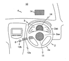
- a vehicle light-emitting device (hereinafter simply referred to as a light-emitting device) according to the present invention is mounted in a cab of a vehicle 10.
- the vehicle 10 is an automobile.
- the vehicle light-emitting device includes a light-emitting panel 11.
- the light emitting panel 11 is a light source body that emits surface light such as an organic EL light emitting element.
- the light emitting surface of the light emitting panel 11 is located in front of the driver's seat 5 (FIG. 2) in the vehicle 10, and emits surface light from the front of the vehicle 10 toward the rear toward the driver's seat 5.
- the light-emitting panel 11 is installed in the driver's cab of the vehicle 10 so that light emitted from the light-emitting surface is irradiated mainly toward the face of a driver (not shown) sitting in the driver's seat 5.
- the light emitting panel 11 can be provided at the center of the steering handle 2a of the traveling steering device 2. Since the steering handle 2a is located almost in front of the driver, it is a suitable installation position from the viewpoint of irradiating blue light toward the driver's face.
- an organic EL light-emitting panel is used as the light-emitting panel 11, and the light-emitting panel 11 is provided at an arbitrary position on the steering handle 2a such as the center portion 2ab and the grip portion 2ab of the steering handle 2a by utilizing its thin and flexible characteristics. be able to.
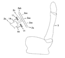
- the light emitting panel 11 can be supported on the bearing support portion 2 c of the handle shaft 2 b of the traveling steering device 2.
- the light emitting panel 11 is supported so that the light from the light emitting surface of the light emitting panel 11 is directed to the face of the boarding driver via the space 2ac between the center portion 2aa of the steering handle 2a and the grip portion 2ab.
- the light emitting panel 11 is fixed on the bearing support portion 2 c by the support portion 14. Even when the light emitting panel 11 is supported in this manner, it is possible to irradiate blue light toward the driver's face.
- the light-emitting panel 11 can be a donut-shaped panel 11 centered on the handle shaft 2c, for example.
- the light emission panel 11 can also be made into the pair of horseshoe-shaped panels 11a and 11b point-symmetrical with respect to the central axis of the handle shaft 2c, for example.
- the light emission panel 11 can also be made into the some panel 11a, 11b, and 11c arrange
- FIG. 3 (d) is a perspective view showing the handle shaft 2c and the light emitting panel 11 together with the steering handle 2a in the case of FIG. 3 (a).
- the light emitting panel 11 is placed in a cylindrical area 2f surrounding the rotational movement locus 2e of the farthest point 2d of the steering handle 2a with the handle shaft 2c, which is the rotation center axis of the steering handle 2a, as the axis center. Can be provided.
- the light emitting panel 11 can also be provided in the indicator unit 3.
- the indicator unit 3 is, for example, an operation speed display panel or a fuel remaining amount indicator.
- the indicator unit 3 for displaying the driving speed and the like is a suitable installation position because it is located in front of the driver. Further, since the driver intermittently moves his / her line of sight to the indicator unit 3 in order to check the driving speed and the like, it can be said to be a suitable installation position from the viewpoint that blue light easily enters the eyes of the driver. Further, from the viewpoint of making the display of the indicator unit 3 easy to see, for example, a transparent organic EL light emitting panel is used as the light emitting panel 11.
- the additional light emitting panel 14 can be provided on the windshield 4. In this case, it is preferable to provide in front of the driver. It is preferable to provide on the upper side or the lower side in the region of the windshield 4 so as not to obstruct the front vision. From the viewpoint of improving the front field of view, it is preferable to use a transparent element such as an organic EL light emitting element as the light emitting panel 11.
- An organic EL light emitting element generally comprises an organic layer including a light emitting layer and two electrode layers sandwiching the organic layer. A light transmissive electrode material such as ITO (Indium-tin-oxide) is applied to these electrode layers. By using it, the light emitting panel 11 can be made transparent.
- the light emitting panel 11 is detachably fixed to the steering handle 2 a of the traveling steering device 2, and the driving power generation unit 12 a of the light emitting device 1 is attached to an accessory power source such as a cigarette lighter 6 provided on the vehicle 10.
- the driving power generated by the driving power generation unit 12a from the power source of the cigarette lighter 6 is supplied to the light emitting panel 11 via the relay unit 12b which is a longitudinal flexible cord.
- the relay portion 12b that is a power supply wiring may be built in the bearing support portion 2c or fixed on the bearing support portion 2c. it can.
- the driving unit 12 supplies driving power to the light emitting panel 11 to emit light.
- the light emitted from the light emitting panel 11 includes a blue component.
- the wavelength range of the blue component is 400 to 490 nm. From the viewpoint of enhancing the melatonin secretion inhibitory effect that induces sleepiness, it is particularly effective to use blue light having a peak around a wavelength of 470 nm.
- the emission color is not limited to a single blue color, and may be a color such as cool white whose spectrum mainly includes a blue component. Thus, if the emission color includes a color component other than the blue component, it is possible to cope with a driver who is not good at a single blue color.
- the light emitting panel 11 may have a so-called RGB configuration capable of emitting red and green light in addition to blue.
- RGB configuration capable of emitting red and green light in addition to blue.
- toning is possible.
- the light-emitting panel 11 can be used as white illumination in a time zone where sleepiness suppression is not necessary, such as in the daytime.
- a diffusion film can be attached to the light emitting surface to give a soft blue color that is soft to the eyes.
- the driving unit 12 supplies driving power to the light emitting panel 11.
- the drive unit 12 adjusts the supply of drive power according to an output signal from at least one of the engine rotation sensor 16, the speed sensor 17, the rider's biological information sensor 18, and the brightness sensor 19 of the vehicle 10. Can do.
- the drive unit 12 selects a light emission mode in response to detection of engine operation of the vehicle 10 or detection of a traveling state of the vehicle 10 and supplies drive power to the light emission panel 11.
- the drive unit 12 selects the light emission stop mode in response to detection of the engine stop of the vehicle 10 or the travel stop state of the vehicle 10, and stops the supply of drive power to the light emitting panel 11.
- the drive part 12 can also increase / decrease the drive electric energy to the light emission panel 11 with progress of time.
- the driving unit 12 selectively drives at least one of a plurality of light emitting panels having different light emitting colors constituting the light emitting panel 11 in order to change the light emitting color of the light emitting panel 11 according to the time zone. Electric power can also be supplied.
- the drive unit 12 may be configured by a drive power generation unit 12a, a relay unit 12b, and a control unit 12c.
- the driving power generation unit 12 a generates driving power
- the relay unit 12 b relays the driving power to the light emitting panel 11.
- the drive power generation unit 12a is attached to the cigarette lighter 6 (FIG. 1), for example, and generates drive power based on the power source.
- the driving power is relayed to the light emitting panel 11 via the relay portion 12b that is a longitudinal flexible cord.
- the control unit 12c receives the output signals of the sensors 16 to 19 via the multiplexer 20, and controls the drive power generation unit 12a according to the output signals. Specifically, when it is determined that the engine (not shown) of the vehicle 10 is operating, or when it is determined that the vehicle 10 is in a traveling state, the control unit 12c selects the light emission mode and drives it. A drive command is issued to the power generation unit 12a. With such a configuration, the blue light is emitted toward the driver before the start of driving, i.e., before becoming sleepy, so that the effect of suppressing the dozing can be sufficiently expected. Further, when detecting the stop of the engine and / or running, the control unit 12c selects the light emission stop mode and issues a stop command to the drive power generation unit 12a.
- the control unit 12c can start time counting immediately after issuing a drive command for the first time, and can also issue a luminance change command to the drive power generation unit 12a after a predetermined time such as 30 minutes elapses.
- the control unit 12c may issue the command only once, or may issue the command a predetermined number of times, for example, 3 times at a predetermined interval such as 10 minutes.
- the control unit 12c issues a luminance change command for increasing the luminance three times every 10 minutes from the time when 30 minutes have elapsed since the start of the engine was detected.
- the control unit 12c issues a drive command to the drive power generation unit 12a according to the lighting instruction input via the input interface 15 by the driver, and the drive power generation unit 12a according to the input turn-off instruction.
- a stop command can be issued.
- the control unit 12c can issue a luminance change command to the drive power generation unit 12a in accordance with the input luminance change instruction.
- control unit 12c issues a drive command to the drive power generation unit 12a when it is determined that the current time is night based on the output signal of the brightness sensor 19 that detects the brightness around the vehicle 10, When it is determined that the time does not correspond to nighttime, it is possible not to issue a drive command to the dynamic power generation unit 12a.
- control unit 12c responds to the input white light emission instruction, and the organic EL corresponding to a specific color among the plurality of organic EL light emitting elements corresponding to blue, red, and green constituting the light emitting panel 11 respectively. It is also possible to issue a drive command for instructing the start of supply of drive current only to the light emitting elements to the dynamic power generation unit 12a.
- control unit 12c can adjust the driving power based on the output parameter of the biological information sensor 18 indicating the awakening state of the boarding driver of the vehicle 10. For example, an imaging device (not shown) that captures the face of the boarding driver and a face recognition process on the video data obtained by the imaging, and the time when the eyelid of the boarding driver is closed (closing time and And a video processing unit that issues a drowsiness detection signal when the closing time is determined to be equal to or greater than a predetermined threshold.
- the control unit 12c issues a drive power adjustment command such as increasing the drive power amount according to the sleepiness detection signal to the drive power generation unit 12a.
- the input unit 13 is an input interface such as a push button.
- the driver can input a turn-on instruction, a turn-off instruction, a brightness change instruction, and a white light emission instruction via the input unit 13.
- the subroutine shown in FIG. 5 is repeatedly executed by the control unit 12c.
- control unit 12c determines whether the engine of the vehicle 10 is in an operating state or whether the vehicle 10 is in a traveling state (step S10). When the control unit 12c does not detect the engine operation or the running state, the control unit 12c ends the routine. (Step S10).
- Control part 12c discriminate
- control unit 12c determines that the current time is nighttime
- the control unit 12c selects a light emission mode and issues a drive command to the drive power generation unit 12a.
- the drive power generation unit 12a supplies a drive current to the light emitting panel 11 in response to a drive command from the control unit 12c.
- the light emitting panel 11 receives the drive current supplied from the drive power generation unit 12a and starts to emit light including a blue component (step S12).
- the controller 12c can also perform the following operations after the light emission is started.
- the controller 12c starts time counting immediately after issuing a drive command for the first time, and issues a luminance change command to the drive power generator 12a when a predetermined time has elapsed from the start of light emission.
- the control unit 12c issues a luminance change command for increasing the luminance three times every five minutes from the time when 30 minutes have elapsed after the engine start is detected.
- the drive power generation unit 12a increases the amount of drive current supplied to the light emitting panel 11 three times every 5 minutes.
- the light emitting panel 11 emits light including a blue component with luminance according to the amount of drive current supplied from the drive unit 12.
- control unit 12c determines whether or not the engine of the vehicle 10 is stopped or whether the vehicle 10 is in a travel stop state (step S13).
- control unit 12c selects the light emission stop mode and issues a stop command to the drive power generation unit 12a.
- the drive power generation unit 12a stops the supply of drive current to the light emitting panel 11 in response to a stop command from the control unit 12c.
- the light emitting panel 11 is turned off when the supply of the drive current is stopped (step S14).
- the light emitting panel 11 is positioned in front of the driver seat 5 in the vehicle 10. Then, the light including the blue component is surface-emitted toward the driver's seat 5 from the front to the rear of the vehicle 10.
- the blue light can surely enter the driver's field of view and the drowsiness suppression effect can be enhanced. Further, even when a cushion or a mat is laid on the driver's seat, there is no possibility that the blue light from the light emitting panel 11 is blocked.
- surface light is emitted toward the driver's face, unnecessary reflected light or scattered light does not enter the driver's field of view and hinder driving operation.
- the light-emitting panel 11 an organic EL light-emitting element
- various features on the front side of the driver such as the travel steering device 2 and additionally the indicator unit 3 and the windshield 4 can be used by utilizing its thinness and flexible characteristics. It is possible to install at a position. By installing it in front of the driver, the drowsiness suppressing effect can be further enhanced.
- the organic EL light emitting element emits soft light by surface light emission, there is also an effect that the driver is gentle on the driver's eyes and is not easily fatigued as compared with the case where light having high directivity such as an LED is used.
- the luminance can be gradually increased as time passes. According to such a configuration, it is possible to increase the brightness of the driver's eyes by reducing the brightness immediately after the start of driving, and to increase the brightness when sleepiness increases with the passage of time. . Moreover, since blue light emission can also be started from the time of detecting engine start-up, the secretion of hormones that cause sleepiness can be suppressed before becoming sleepy. Therefore, the effect of preventing accidents from occurring before starting to drive can be further expected.
- the above embodiment is an example in which the vehicle 10 is an automobile, but is not limited thereto.
- the light emitting device of the present invention can be applied to various vehicles including a traveling steering device such as a motorcycle, a bicycle, a ship, an airplane, a train, a train, and a locomotive.
Landscapes
- Engineering & Computer Science (AREA)
- Mechanical Engineering (AREA)
- Arrangements Of Lighting Devices For Vehicle Interiors, Mounting And Supporting Thereof, Circuits Therefore (AREA)
- Lighting Device Outwards From Vehicle And Optical Signal (AREA)
Priority Applications (1)
| Application Number | Priority Date | Filing Date | Title |
|---|---|---|---|
| PCT/JP2012/064673 WO2013183144A1 (fr) | 2012-06-07 | 2012-06-07 | Unité d'émission de lumière pour véhicule |
Applications Claiming Priority (1)
| Application Number | Priority Date | Filing Date | Title |
|---|---|---|---|
| PCT/JP2012/064673 WO2013183144A1 (fr) | 2012-06-07 | 2012-06-07 | Unité d'émission de lumière pour véhicule |
Publications (1)
| Publication Number | Publication Date |
|---|---|
| WO2013183144A1 true WO2013183144A1 (fr) | 2013-12-12 |
Family
ID=49711561
Family Applications (1)
| Application Number | Title | Priority Date | Filing Date |
|---|---|---|---|
| PCT/JP2012/064673 Ceased WO2013183144A1 (fr) | 2012-06-07 | 2012-06-07 | Unité d'émission de lumière pour véhicule |
Country Status (1)
| Country | Link |
|---|---|
| WO (1) | WO2013183144A1 (fr) |
Cited By (2)
| Publication number | Priority date | Publication date | Assignee | Title |
|---|---|---|---|---|
| GB2605827A (en) * | 2021-04-15 | 2022-10-19 | Manning Peter | Night driving aid |
| US20240149786A1 (en) * | 2022-11-04 | 2024-05-09 | Ferrari S.P.A. | Motor vehicle with steering wheel provided with an illuminable portion |
Citations (6)
| Publication number | Priority date | Publication date | Assignee | Title |
|---|---|---|---|---|
| JP2005067367A (ja) * | 2003-08-22 | 2005-03-17 | Semiconductor Energy Lab Co Ltd | 発光装置および運転支援システムおよびヘルメット |
| JP2007055561A (ja) * | 2005-08-26 | 2007-03-08 | Fujitsu Ten Ltd | 情報提示装置 |
| JP2008027044A (ja) * | 2006-07-19 | 2008-02-07 | Hino Motors Ltd | 注意喚起装置 |
| JP2008137639A (ja) * | 2006-11-06 | 2008-06-19 | Quality Kk | 車両制御装置および車両制御プログラム |
| JP2008167806A (ja) * | 2007-01-09 | 2008-07-24 | Denso Corp | 眠気検知装置 |
| JP2011065561A (ja) * | 2009-09-18 | 2011-03-31 | Yupiteru Corp | 車載用電子機器及びプログラム |
-
2012
- 2012-06-07 WO PCT/JP2012/064673 patent/WO2013183144A1/fr not_active Ceased
Patent Citations (6)
| Publication number | Priority date | Publication date | Assignee | Title |
|---|---|---|---|---|
| JP2005067367A (ja) * | 2003-08-22 | 2005-03-17 | Semiconductor Energy Lab Co Ltd | 発光装置および運転支援システムおよびヘルメット |
| JP2007055561A (ja) * | 2005-08-26 | 2007-03-08 | Fujitsu Ten Ltd | 情報提示装置 |
| JP2008027044A (ja) * | 2006-07-19 | 2008-02-07 | Hino Motors Ltd | 注意喚起装置 |
| JP2008137639A (ja) * | 2006-11-06 | 2008-06-19 | Quality Kk | 車両制御装置および車両制御プログラム |
| JP2008167806A (ja) * | 2007-01-09 | 2008-07-24 | Denso Corp | 眠気検知装置 |
| JP2011065561A (ja) * | 2009-09-18 | 2011-03-31 | Yupiteru Corp | 車載用電子機器及びプログラム |
Cited By (3)
| Publication number | Priority date | Publication date | Assignee | Title |
|---|---|---|---|---|
| GB2605827A (en) * | 2021-04-15 | 2022-10-19 | Manning Peter | Night driving aid |
| US20240149786A1 (en) * | 2022-11-04 | 2024-05-09 | Ferrari S.P.A. | Motor vehicle with steering wheel provided with an illuminable portion |
| US12337753B2 (en) * | 2022-11-04 | 2025-06-24 | Ferrari S.P.A. | Motor vehicle with steering wheel provided with an illuminable portion |
Similar Documents
| Publication | Publication Date | Title |
|---|---|---|
| JP4580288B2 (ja) | 運転支援自動車 | |
| CN107869670B (zh) | 具有用于机动车辆乘客舱的动态照明效果的照明装置 | |
| CN105034939B (zh) | 带有低光强设置的车辆阅读灯 | |
| JP6622250B2 (ja) | 車両用警告装置 | |
| JP2003040033A (ja) | 視界補助装置 | |
| JP2008189201A (ja) | 車両用視認補助装置 | |
| KR20140142914A (ko) | 자동차 시트의 일루미네이팅 장치 및 그 제어 방법 | |
| JP2016060313A (ja) | 車両用室内照明装置 | |
| KR20210101128A (ko) | 차 실내 조명 시스템, 차 실내 조명 시스템을 동작시키는 방법, 및 기억 매체 | |
| JP2026509682A (ja) | 車両乗員検出装置及び車両 | |
| JP2015212125A (ja) | 車両用室内灯装置 | |
| JP2008204727A (ja) | 車両用前照灯装置 | |
| US20240149787A1 (en) | Luminous gear shift for turning on a road vehicle and relative road vehicle | |
| JP6064301B2 (ja) | 車両用メータ装置 | |
| JP2013014297A (ja) | 降車者の足下を照らすランプを備えた車両 | |
| JP4396903B1 (ja) | 表示装置 | |
| KR102695903B1 (ko) | 차량용 램프 시스템 | |
| JP6228048B2 (ja) | 電動アシスト自転車 | |
| US20240149676A1 (en) | Luminous lever for turning on a road vehicle and relative road vehicle | |
| CN117841827A (zh) | 用于车辆内部空间的照明的方法以及用于执行这种方法的踏板组件 | |
| JP2013014296A (ja) | 降車者の足下を照らすランプを備えた車両 | |
| JP4589829B2 (ja) | 運転者覚醒維持装置 | |
| JP2014029271A (ja) | 車両用表示装置 | |
| JP5018912B2 (ja) | 視界補助装置 | |
| US20240149897A1 (en) | Gesture device for turning on a road vehicle and relative road vehicle |
Legal Events
| Date | Code | Title | Description |
|---|---|---|---|
| 121 | Ep: the epo has been informed by wipo that ep was designated in this application |
Ref document number: 12878489 Country of ref document: EP Kind code of ref document: A1 |
|
| NENP | Non-entry into the national phase |
Ref country code: DE |
|
| 122 | Ep: pct application non-entry in european phase |
Ref document number: 12878489 Country of ref document: EP Kind code of ref document: A1 |
|
| NENP | Non-entry into the national phase |
Ref country code: JP |