WO2013183156A1 - Dispositif d'affichage par projection - Google Patents
Dispositif d'affichage par projection Download PDFInfo
- Publication number
- WO2013183156A1 WO2013183156A1 PCT/JP2012/064740 JP2012064740W WO2013183156A1 WO 2013183156 A1 WO2013183156 A1 WO 2013183156A1 JP 2012064740 W JP2012064740 W JP 2012064740W WO 2013183156 A1 WO2013183156 A1 WO 2013183156A1
- Authority
- WO
- WIPO (PCT)
- Prior art keywords
- scanning
- lens
- laser light
- projection display
- projection
- Prior art date
- Legal status (The legal status is an assumption and is not a legal conclusion. Google has not performed a legal analysis and makes no representation as to the accuracy of the status listed.)
- Ceased
Links
Images


Classifications
-
- G—PHYSICS
- G03—PHOTOGRAPHY; CINEMATOGRAPHY; ANALOGOUS TECHNIQUES USING WAVES OTHER THAN OPTICAL WAVES; ELECTROGRAPHY; HOLOGRAPHY
- G03B—APPARATUS OR ARRANGEMENTS FOR TAKING PHOTOGRAPHS OR FOR PROJECTING OR VIEWING THEM; APPARATUS OR ARRANGEMENTS EMPLOYING ANALOGOUS TECHNIQUES USING WAVES OTHER THAN OPTICAL WAVES; ACCESSORIES THEREFOR
- G03B21/00—Projectors or projection-type viewers; Accessories therefor
- G03B21/14—Details
- G03B21/142—Adjusting of projection optics
-
- G—PHYSICS
- G03—PHOTOGRAPHY; CINEMATOGRAPHY; ANALOGOUS TECHNIQUES USING WAVES OTHER THAN OPTICAL WAVES; ELECTROGRAPHY; HOLOGRAPHY
- G03B—APPARATUS OR ARRANGEMENTS FOR TAKING PHOTOGRAPHS OR FOR PROJECTING OR VIEWING THEM; APPARATUS OR ARRANGEMENTS EMPLOYING ANALOGOUS TECHNIQUES USING WAVES OTHER THAN OPTICAL WAVES; ACCESSORIES THEREFOR
- G03B21/00—Projectors or projection-type viewers; Accessories therefor
- G03B21/14—Details
- G03B21/20—Lamp housings
- G03B21/2006—Lamp housings characterised by the light source
- G03B21/2033—LED or laser light sources
-
- G—PHYSICS
- G03—PHOTOGRAPHY; CINEMATOGRAPHY; ANALOGOUS TECHNIQUES USING WAVES OTHER THAN OPTICAL WAVES; ELECTROGRAPHY; HOLOGRAPHY
- G03B—APPARATUS OR ARRANGEMENTS FOR TAKING PHOTOGRAPHS OR FOR PROJECTING OR VIEWING THEM; APPARATUS OR ARRANGEMENTS EMPLOYING ANALOGOUS TECHNIQUES USING WAVES OTHER THAN OPTICAL WAVES; ACCESSORIES THEREFOR
- G03B21/00—Projectors or projection-type viewers; Accessories therefor
- G03B21/14—Details
- G03B21/28—Reflectors in projection beam
-
- G—PHYSICS
- G03—PHOTOGRAPHY; CINEMATOGRAPHY; ANALOGOUS TECHNIQUES USING WAVES OTHER THAN OPTICAL WAVES; ELECTROGRAPHY; HOLOGRAPHY
- G03B—APPARATUS OR ARRANGEMENTS FOR TAKING PHOTOGRAPHS OR FOR PROJECTING OR VIEWING THEM; APPARATUS OR ARRANGEMENTS EMPLOYING ANALOGOUS TECHNIQUES USING WAVES OTHER THAN OPTICAL WAVES; ACCESSORIES THEREFOR
- G03B33/00—Colour photography, other than mere exposure or projection of a colour film
- G03B33/06—Colour photography, other than mere exposure or projection of a colour film by additive-colour projection apparatus
-
- H—ELECTRICITY
- H04—ELECTRIC COMMUNICATION TECHNIQUE
- H04N—PICTORIAL COMMUNICATION, e.g. TELEVISION
- H04N9/00—Details of colour television systems
- H04N9/12—Picture reproducers
- H04N9/31—Projection devices for colour picture display, e.g. using electronic spatial light modulators [ESLM]
- H04N9/3129—Projection devices for colour picture display, e.g. using electronic spatial light modulators [ESLM] scanning a light beam on the display screen
-
- H—ELECTRICITY
- H04—ELECTRIC COMMUNICATION TECHNIQUE
- H04N—PICTORIAL COMMUNICATION, e.g. TELEVISION
- H04N9/00—Details of colour television systems
- H04N9/12—Picture reproducers
- H04N9/31—Projection devices for colour picture display, e.g. using electronic spatial light modulators [ESLM]
- H04N9/3141—Constructional details thereof
- H04N9/3173—Constructional details thereof wherein the projection device is specially adapted for enhanced portability
-
- G—PHYSICS
- G03—PHOTOGRAPHY; CINEMATOGRAPHY; ANALOGOUS TECHNIQUES USING WAVES OTHER THAN OPTICAL WAVES; ELECTROGRAPHY; HOLOGRAPHY
- G03B—APPARATUS OR ARRANGEMENTS FOR TAKING PHOTOGRAPHS OR FOR PROJECTING OR VIEWING THEM; APPARATUS OR ARRANGEMENTS EMPLOYING ANALOGOUS TECHNIQUES USING WAVES OTHER THAN OPTICAL WAVES; ACCESSORIES THEREFOR
- G03B21/00—Projectors or projection-type viewers; Accessories therefor
- G03B21/14—Details
- G03B21/20—Lamp housings
- G03B21/2006—Lamp housings characterised by the light source
- G03B21/2013—Plural light sources
Definitions
- the present invention relates to a scanning projection display device.
- Some projection display devices can project a two-dimensional image or video onto a projection surface by scanning a laser beam vertically and horizontally. Since such a scanning projection display device generally has a simple structure, it can be reduced in size and price.
- Patent Document 1 discloses a scanning projection display device.
- the scanning projection display device includes red (R), green (G), and blue (B) laser light sources, a cross prism, a scanning mirror, a light valve, and a projection lens. .
- laser light sources of the respective colors are generated, and the laser light reflected by the cross prism is reflected by the scanning mirror to become rectangular two-dimensional scanning light.
- This two-dimensional scanning light is incident on the light valve, modulated, and then enlarged and projected as an image or video by the projection lens.
- the scanning projection display apparatus can project an image or a video on the projection surface.
- an object of the present invention is to provide a small scanning projection display device.
- the projection display device of the present invention is a projection display device in which laser light emitted from a light source, reflected by a scanning mirror, and two-dimensionally scanned is modulated by a light valve and then enlarged and projected by a projection lens.
- the F mirror of the scanning mirror is smaller than the F number of the projection lens, and has a lens for reducing the irradiation area of the laser light reflected by the scanning mirror to the light valve.
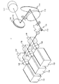
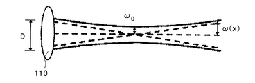
- FIG. 1 is a schematic configuration diagram of a projection display device according to a first embodiment of the present invention. It is explanatory drawing of the beam diameter of the laser beam which permeate
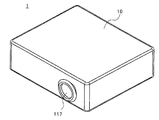
- FIG. 2 is a perspective view of the projection display device shown in FIG. 1. It is a schematic block diagram of the projection type display apparatus which concerns on the 2nd Embodiment of this invention.
- FIG. 1 is a schematic configuration diagram of a projection display device 1 according to the present embodiment.
- the projection display apparatus 1 first, laser light emitted from the laser light sources 101, 102, and 103 is incident on the condenser lens 110 via the collimator lenses 104, 105, and 106 and the dichroic prisms 107, 108, and 109.
- the laser light transmitted through the condensing lens 110 is sequentially reflected by the vertical scanning mirror 111 and the horizontal scanning mirror 112 and enters the collimator lens 113 as rectangular two-dimensional scanning light.
- the two-dimensional scanning light transmitted through the collimator lens 113 is reflected by the folding mirror 114 and enters a DMD (Digital Micromirror Device) 116 that is a light valve configured as an assembly of a large number of mirrors via the cover glass 115.
- the two-dimensional scanning light modulated by the DMD 116 based on the image signal or the video signal is enlarged and projected on the projection surface via the projection lens 117.
- the laser light sources 101, 102, and 103 generate laser beams of three primary colors of red (R), green (G), and blue (B), respectively, in a several watt class. That is, the laser light source 101 generates laser light having a wavelength in the red region (about 640 nm), the laser light source 102 generates laser light having a wavelength in the green region (about 530 nm), and the laser light source 103 has a wavelength in the blue region (440 nm). (About) laser beam is generated.
- the laser light sources 101, 102, and 103 are arranged so that the laser beams generated by the laser light sources 101, 102, and 103 are translated.
- the cross section of the light beam generated by each laser light source 101, 102, 103 is a circle or an ellipse having a predetermined diameter.
- Each laser light source 101, 102, 103 oscillates laser light in pulses. That is, the laser light sources 101, 102, and 103 are repeatedly switched on and off at different timings. Therefore, in the projection display device 1 according to the present embodiment, it is not necessary to provide a member such as a color wheel for changing white light to each color, and thus the size can be reduced.
- the collimator lenses 104, 105, and 106 adjust the laser beams generated by the laser light sources 101, 102, and 103 so as to be parallel beams and to have a desired beam diameter.
- each laser light source 101, 102, 103 uses a laser beam that emits a laser beam whose cross section is not circular, such as a semiconductor laser
- the collimator lenses 104, 105, 106 have a circular cross section of each laser beam. Also plays a role.
- the dichroic prisms 108, 109, and 110 are members that reflect red, green, and blue laser beams and transmit light of other colors, respectively. That is, the red laser light that has passed through the collimator lens 104 is reflected by the dichroic prism 107, passes through the dichroic prisms 108 and 109, and enters the condenser lens 110. The green laser light that has passed through the collimator lens 105 is reflected by the dichroic prism 108, passes through the dichroic prism 109, and enters the condenser lens 110. The blue laser light transmitted through the collimator lens 106 is reflected by the dichroic dichroic prism 109 and enters the condenser lens 110. In the present embodiment, the dichroic prism 107 only needs to have a function of reflecting red laser light, and thus can be replaced with a normal mirror.
- the condensing lens 110 is a lens for adjusting the beam diameter of the laser light incident on each lens of the DMD 116.
- the laser light that has passed through the condenser lens 110 becomes a Gaussian beam.
- the beam diameter ⁇ (X) of the laser beam that has passed through the condenser lens 110 is expressed by the following equation.
- ⁇ 0 represents the beam diameter at the beam waist
- X represents the distance from the beam waist
- ⁇ represents the wavelength of the laser beam.
- the beam diameter ⁇ (X) increases as the distance from the position of the beam waist increases. Note that the position of the beam waist depends on the focal length f of the condenser lens 110.
- the beam diameter ⁇ 0 at the beam waist is expressed by the following equation.
- D represents the initial beam diameter incident on the condenser lens 110.
- the beam diameter ⁇ 0 at the beam waist depends on the initial beam diameter D.
- the size of the initial beam diameter D is determined by the collimator lenses 104, 105, and 106.
- the beam diameter of the laser light incident on each mirror of the DMD 116 can be determined by adjusting the focal length of the condenser lens 110 according to the initial beam diameter D.
- the vertical scanning mirror 111 and the horizontal scanning mirror 112 are formed using a MEMS (Micro Electro Mechanical Systems) technology.
- the vertical scanning mirror 111 is driven such that the reflection surface that reflects the laser light reciprocates at a predetermined frequency in the vertical direction.
- the horizontal scanning mirror 112 is driven such that the reflection surface that reflects the laser light performs reciprocal scanning of the reflected laser light at a predetermined frequency in the horizontal direction. In this manner, the laser light sequentially reflected by the vertical scanning mirror 111 and the horizontal scanning mirror 112 is reciprocally scanned in the vertical direction and the horizontal direction orthogonal to each other to become two-dimensional scanning light.
- the scanning angle of the vertical scanning mirror 111 is ⁇ V
- the scanning angle of the horizontal scanning mirror 112 is ⁇ H.
- the laser beam reflected by the vertical scanning mirror 111 is reciprocally scanned in the vertical direction at a scanning angle ⁇ V, and enters the horizontal scanning mirror 112 while drawing a sine curve in the vertical direction.
- the laser beam reflected by the horizontal scanning mirror 112 is reciprocally scanned in the horizontal direction at a scanning angle ⁇ H, and enters the collimator lens 113 while drawing a sine curve not only in the vertical direction but also in the horizontal direction.
- the horizontal scanning mirror 112 is driven at a higher frequency than the vertical scanning mirror 111.
- the driving frequency of the vertical scanning mirror 111 is 60 Hz
- the driving frequency of the horizontal scanning mirror 112 is several kHz to several tens of kHz.
- FIG. 4 shows an image of the laser light incident on the collimator lens 113 in the quarter period of the vertical scanning mirror 111.
- the vertical direction is indicated by an arrow DV
- the horizontal direction is indicated by an arrow DH.
- the two-dimensional scanning light incident on the collimator lens 113 is scanned in the horizontal direction DH for a plurality of cycles while being scanned in the vertical direction DV for a quarter cycle.
- the scanning speed of the laser light is slow at both ends of the vertical direction DV and the horizontal direction DH. Therefore, the two-dimensional scanning light reflected by the scanning mirrors 111 and 112 has high illuminance at both ends in the vertical direction DV and the horizontal direction DH. In the vertical direction DV, the scanning speed of the laser light is slow, so that an illuminance difference between the both ends of the vertical direction DV and the other portions hardly appears. However, in the horizontal direction DH, since the scanning speed of the laser beam is high, the illuminance difference between the both end portions in the vertical direction DV and the other portions appears remarkably.
- the area surrounded by the broken line shown in FIG. 4 is called a blanking area.
- the blanking region is a region with high illuminance generated because the scanning speed of the laser beam in the horizontal direction DH direction is low.
- the projection display device 1 can be downsized.
- two one-dimensional scanning mirrors 111 and 112 are used as scanning mirrors for obtaining two-dimensional scanning light.
- a single two-dimensional scanning mirror may be used to obtain two-dimensional scanning light.
- the collimator lens 113 is a lens for adjusting the F number of the scanning mirrors 111 and 112. Details thereof will be described below.
- the F numbers of the scanning mirrors 111 and 112 are expressed as follows using ⁇ V and ⁇ H shown in FIG.
- the F number of the scanning mirrors 111 and 112 needs to be equal to or greater than the F number of the projection lens 117. This is because, when the F number of the scanning mirrors 111 and 112 is smaller than the F number of the projection lens 117, the spread of the two-dimensional scanning light from the scanning mirrors 111 and 112 is large, and a part of the two-dimensional scanning light is projected to the projection lens. This is because 117 may not be transmitted. As a result, a part of the two-dimensional scanning light is lost.
- the F number of the projection lens 117 is generally about 2.0.
- the scanning angles ⁇ V and ⁇ H of the scanning mirrors 111 and 112 are 14.5 °. Therefore, when the F number of the projection lens 117 is 2.0, the scanning angles ⁇ V and ⁇ H of the scanning mirrors 111 and 112 must be 14.5 ° or less.
- the scanning angles ⁇ V and ⁇ H of the scanning mirrors 111 and 112 need to be increased.
- the F number of the scanning mirrors 111 and 112 becomes F of the projection lens 117. It will be smaller than the number of 2.0.
- a collimator lens 113 is provided that makes the scanning angle of the laser light incident on the DMD 116 smaller than the scanning angles ⁇ V and ⁇ H of the scanning mirrors 111 and 112. That is, the collimator lens 113 makes the incident angle of the laser light to the DMD 116 smaller than the scanning angles ⁇ V and ⁇ H of the scanning mirrors 111 and 112. Thereby, the irradiation range with respect to DMD116 of the laser beam reflected by the scanning mirrors 111 and 112 is reduced.
- the F number of the entire optical unit of the scanning mirrors 111 and 112 and the collimator lens 113 is changed to the F number of the projection lens 117. It can be 2.0 or more. In other words, all of the two-dimensional scanning light transmitted through the collimator lens 113 and modulated by the DMD 116 enters the projection lens 117. Thereby, the optical path between the scanning mirrors 111 and 112 and the DMD 116 can be shortened without reducing the two-dimensional scanning light, and the scanning projection display device 1 can be downsized.
- the lens 113 only needs to be able to fit the two-dimensional scanning light reflected by the scanning mirrors 111 and 112 into a diameter that the projection lens 117 can capture.
- a collimator lens is used as the lens 113, but the lens 113 may be any lens that can reduce the overall F number of the scanning mirrors 111 and 112 and the lens 113.
- the lens 113 may be any lens that can make the scanning angle of at least one of the vertical direction and the horizontal direction of the laser light incident on the DMD 116 smaller than the scanning angle of the scanning mirrors 111 and 112.
- the folding mirror 114 is provided for adjusting the angle of the two-dimensional scanning light incident on the DMD 116.
- the folding mirror 114 can be corrected, for example, from an irradiation area indicated by a broken line to an irradiation area indicated by a solid line in accordance with the position of the DMD 116.
- the folding mirror 114 may or may not be installed depending on the optical path design in the projection display device 1. When the folding mirror 114 is not installed, the laser light transmitted through the lens 113 is directly incident on the DMD 116 from the DMD cover 115.
- the DMD 116 is an optical element that modulates two-dimensional scanning light of laser light based on an image signal or a video signal.
- the DMD 116 has a large number of mirrors arranged in a rectangular shape, and laser light is incident on individual mirrors.
- Each mirror of the DMD 116 individually switches the direction of the reflecting surface, and is turned on or off. That is, each mirror causes the laser beam incident when it is in the on state to enter the projection lens 117, and does not allow the laser beam incident when it is in the off state to enter the projection lens 117. Thereby, the DMD 116 modulates the incident two-dimensional scanning light.
- the modulation of the two-dimensional scanning light is performed by the DMD 116, but the modulation of the two-dimensional scanning light can also be performed by the laser light sources 101, 102, and 103. That is, it is possible to modulate the two-dimensional scanning light by changing the output of the laser light from each of the laser light sources 101, 102, 103 in accordance with the image signal or the video signal.
- the modulation of the two-dimensional scanning light by the laser light sources 101, 102, 103 is more suitable than the modulation of the two-dimensional scanning light by the DMD 116.
- the modulation of the two-dimensional scanning light by the DMD 116 and the modulation of the two-dimensional scanning light by the laser light sources 101, 102, 103 can be combined. Thereby, it is possible to display an image or video with higher contrast.
- the projection lens 117 enlarges and projects the light incident from the DMD 116 onto the projection surface.
- a lens having an F number of 1.8 to 2.4 is generally used, but not limited to this, various lenses can be used.
- FIG. 6 is a perspective view of the projection display apparatus 1 according to the present embodiment.
- the projection display apparatus 1 includes a housing 10 that covers the entire members illustrated in FIG. 1, and the housing 10 exposes only the projection lens 117 on the side surface.
- the projection direction of an image or video by the projection display device 1 is changed by changing the direction of the projection lens 117 for each housing 110.
- the laser light projected from the projection lens 117 may directly enter the human eye.
- the laser light sources 101, 102, and 103 which are laser light generation sources, reach the projection lens 117 via various members, and the projection lens 117 further.
- the laser light is diffused widely. Therefore, in the scanning projection display apparatus 1 according to the present embodiment, the laser light projected from the projection lens 117 is weakened, and damage to the eyes due to the laser light projected from the projection lens 117 is suppressed.
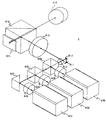
- FIG. 7 is a schematic configuration diagram of the projection display device 6 according to the present embodiment.
- laser light emitted from the laser light sources 601, 602, and 603 is incident on the condenser lens 610 via the collimator lenses 604, 605, and 606 and the dichroic prisms 607, 608, and 609.
- the laser light transmitted through the condensing lens 610 is sequentially reflected by the vertical scanning mirror 611 and the horizontal scanning mirror 612 and enters the lens 613 as rectangular two-dimensional scanning light.
- the two-dimensional scanning light transmitted through the collimator lens 613 is reflected by the polarization beam splitter 614 and enters the reflective liquid crystal panel 615 that is a light valve.
- the two-dimensional scanning light modulated by the reflective liquid crystal panel 615 based on the image signal or the video signal is transmitted through the polarization beam splitter 614 and enlarged and projected onto the projection surface via the projection lens 616.
- the projection display apparatus differs from the projection display apparatus according to the first embodiment in that a reflective liquid crystal panel 615 is used instead of a DMD as a light valve, and other configurations are the same as those in the first embodiment. This is the same as the projection display device according to the embodiment.
- a polarizing beam splitter 614 is provided between the lens 613 and the reflective liquid crystal panel 615.
- the polarization beam splitter 614 reflects the laser light (S-polarized light) that has passed through the lens 613 toward the reflective liquid crystal panel 615, transmits the modulated laser light (P-polarized light) to the reflective liquid crystal panel 615, and projects it. It has a function of making it enter the lens 616.
- the liquid crystal display panel 615 is an optical element that modulates two-dimensional scanning light based on an image signal or a video signal.
- the liquid crystal display panel 615 has a liquid crystal layer. Each part of the liquid crystal layer of the liquid crystal display panel 615 can change the output of the P-polarized laser light emitted to the projection lens 616 by adjusting the electric field applied. Thereby, the liquid crystal display panel 615 modulates the incident two-dimensional scanning light.
- the modulation of the two-dimensional scanning light can be performed not only by the liquid crystal display panel 615 but also by combining the laser light sources 601, 602, 603 and the polarization beam splitter 614.
- the projection lens 616 enlarges and projects the light incident from the liquid crystal display panel 615 via the polarization beam splitter 614 onto the projection surface.
Landscapes
- Physics & Mathematics (AREA)
- General Physics & Mathematics (AREA)
- Optics & Photonics (AREA)
- Engineering & Computer Science (AREA)
- Multimedia (AREA)
- Signal Processing (AREA)
- Mechanical Optical Scanning Systems (AREA)
Priority Applications (2)
| Application Number | Priority Date | Filing Date | Title |
|---|---|---|---|
| PCT/JP2012/064740 WO2013183156A1 (fr) | 2012-06-08 | 2012-06-08 | Dispositif d'affichage par projection |
| US14/405,713 US20150177600A1 (en) | 2012-06-08 | 2012-06-08 | Projection Display Apparatus |
Applications Claiming Priority (1)
| Application Number | Priority Date | Filing Date | Title |
|---|---|---|---|
| PCT/JP2012/064740 WO2013183156A1 (fr) | 2012-06-08 | 2012-06-08 | Dispositif d'affichage par projection |
Publications (1)
| Publication Number | Publication Date |
|---|---|
| WO2013183156A1 true WO2013183156A1 (fr) | 2013-12-12 |
Family
ID=49711572
Family Applications (1)
| Application Number | Title | Priority Date | Filing Date |
|---|---|---|---|
| PCT/JP2012/064740 Ceased WO2013183156A1 (fr) | 2012-06-08 | 2012-06-08 | Dispositif d'affichage par projection |
Country Status (2)
| Country | Link |
|---|---|
| US (1) | US20150177600A1 (fr) |
| WO (1) | WO2013183156A1 (fr) |
Families Citing this family (4)
| Publication number | Priority date | Publication date | Assignee | Title |
|---|---|---|---|---|
| JP2017125942A (ja) * | 2016-01-14 | 2017-07-20 | ソニー株式会社 | レンズモジュール、およびプロジェクタ |
| CN105974580B (zh) * | 2016-07-13 | 2018-04-27 | 武汉理工大学 | 一种数字式快速轴向扫描模块 |
| JP6964093B2 (ja) * | 2016-12-12 | 2021-11-10 | ソニーセミコンダクタソリューションズ株式会社 | 投影光学系、画像投影装置、および画像投影システム |
| CN116449633A (zh) * | 2023-03-23 | 2023-07-18 | 北京深光科技有限公司 | 带光调制部件和扫描振镜部件的投影光机及投影仪 |
Citations (3)
| Publication number | Priority date | Publication date | Assignee | Title |
|---|---|---|---|---|
| JP2002072966A (ja) * | 2000-06-12 | 2002-03-12 | Matsushita Electric Ind Co Ltd | カラー画像表示装置 |
| WO2006137326A1 (fr) * | 2005-06-20 | 2006-12-28 | Matsushita Electric Industrial Co., Ltd. | Dispositif d’affichage d’image en deux dimensions, source lumineuse d’éclairage, et dispositif d’éclairage d’exposition |
| JP2008175869A (ja) * | 2007-01-16 | 2008-07-31 | Seiko Epson Corp | 光源装置、照明装置、モニタ装置、画像表示装置及びプロジェクタ |
Family Cites Families (1)
| Publication number | Priority date | Publication date | Assignee | Title |
|---|---|---|---|---|
| US6511184B2 (en) * | 2000-04-05 | 2003-01-28 | Matsushita Electric Industrial Co., Ltd. | Color image display apparatus |
-
2012
- 2012-06-08 US US14/405,713 patent/US20150177600A1/en not_active Abandoned
- 2012-06-08 WO PCT/JP2012/064740 patent/WO2013183156A1/fr not_active Ceased
Patent Citations (3)
| Publication number | Priority date | Publication date | Assignee | Title |
|---|---|---|---|---|
| JP2002072966A (ja) * | 2000-06-12 | 2002-03-12 | Matsushita Electric Ind Co Ltd | カラー画像表示装置 |
| WO2006137326A1 (fr) * | 2005-06-20 | 2006-12-28 | Matsushita Electric Industrial Co., Ltd. | Dispositif d’affichage d’image en deux dimensions, source lumineuse d’éclairage, et dispositif d’éclairage d’exposition |
| JP2008175869A (ja) * | 2007-01-16 | 2008-07-31 | Seiko Epson Corp | 光源装置、照明装置、モニタ装置、画像表示装置及びプロジェクタ |
Also Published As
| Publication number | Publication date |
|---|---|
| US20150177600A1 (en) | 2015-06-25 |
Similar Documents
| Publication | Publication Date | Title |
|---|---|---|
| US6594090B2 (en) | Laser projection display system | |
| JP5350610B2 (ja) | 投影器のための光学システム及び対応する投影器 | |
| CN102483523B (zh) | 具有被配置用于平面外移动的斑点减少元件的光学激光投影系统 | |
| US8172404B2 (en) | Projection with lenslet arrangement on speckle reduction element | |
| JP5428885B2 (ja) | プロジェクター | |
| KR101796973B1 (ko) | 자유 형상 광학 리다이렉트 장치 | |
| CN102640037A (zh) | 具有弯曲的散斑减少元件表面的光学投影系统 | |
| JP5363061B2 (ja) | 単板投写型表示装置 | |
| JP2012230321A (ja) | 走査型画像表示装置 | |
| WO2013183156A1 (fr) | Dispositif d'affichage par projection | |
| JP6323072B2 (ja) | 照明装置およびプロジェクター | |
| US20100296533A1 (en) | Projection with slow relay and fast projection subsystems | |
| CN101517456A (zh) | 投影显示器 | |
| US7443586B2 (en) | Display device using single-panel diffractive light modulator | |
| JP5515200B2 (ja) | 照明光学系及びプロジェクタ装置 | |
| KR101315981B1 (ko) | 프로젝터 | |
| KR100828365B1 (ko) | 레이저 디스플레이장치 | |
| JP5321558B2 (ja) | スペックル低減装置およびプロジェクタ | |
| WO2010134962A2 (fr) | Projection avec une image intermédiaire plus grande | |
| KR100634001B1 (ko) | 발광 다이오드를 구비한 프리즘 | |
| US20120170005A1 (en) | Projection type display device | |
| KR100224903B1 (ko) | 반사형 프로젝트 장치 | |
| KR20150062355A (ko) | 레이저 광원을 이용하는 프로젝터 | |
| KR20080053792A (ko) | 레이저 광원을 이용하는 프로젝터 | |
| JP2005250123A (ja) | プロジェクタ |
Legal Events
| Date | Code | Title | Description |
|---|---|---|---|
| 121 | Ep: the epo has been informed by wipo that ep was designated in this application |
Ref document number: 12878604 Country of ref document: EP Kind code of ref document: A1 |
|
| WWE | Wipo information: entry into national phase |
Ref document number: 14405713 Country of ref document: US |
|
| NENP | Non-entry into the national phase |
Ref country code: DE |
|
| 122 | Ep: pct application non-entry in european phase |
Ref document number: 12878604 Country of ref document: EP Kind code of ref document: A1 |
|
| NENP | Non-entry into the national phase |
Ref country code: JP |