WO2013183179A1 - 粉粒体供給機における気体送給装置 - Google Patents
粉粒体供給機における気体送給装置 Download PDFInfo
- Publication number
- WO2013183179A1 WO2013183179A1 PCT/JP2012/078699 JP2012078699W WO2013183179A1 WO 2013183179 A1 WO2013183179 A1 WO 2013183179A1 JP 2012078699 W JP2012078699 W JP 2012078699W WO 2013183179 A1 WO2013183179 A1 WO 2013183179A1
- Authority
- WO
- WIPO (PCT)
- Prior art keywords
- granular material
- gas
- bottom plate
- powder
- annular
- Prior art date
- Legal status (The legal status is an assumption and is not a legal conclusion. Google has not performed a legal analysis and makes no representation as to the accuracy of the status listed.)
- Ceased
Links
Images



Classifications
-
- F—MECHANICAL ENGINEERING; LIGHTING; HEATING; WEAPONS; BLASTING
- F26—DRYING
- F26B—DRYING SOLID MATERIALS OR OBJECTS BY REMOVING LIQUID THEREFROM
- F26B17/00—Machines or apparatus for drying materials in loose, plastic, or fluidised form, e.g. granules, staple fibres, with progressive movement
- F26B17/18—Machines or apparatus for drying materials in loose, plastic, or fluidised form, e.g. granules, staple fibres, with progressive movement with movement performed by rotating helical blades or other rotary conveyors which may be heated moving materials in stationary chambers, e.g. troughs
- F26B17/22—Machines or apparatus for drying materials in loose, plastic, or fluidised form, e.g. granules, staple fibres, with progressive movement with movement performed by rotating helical blades or other rotary conveyors which may be heated moving materials in stationary chambers, e.g. troughs the axis of rotation being vertical or steeply inclined
-
- F—MECHANICAL ENGINEERING; LIGHTING; HEATING; WEAPONS; BLASTING
- F26—DRYING
- F26B—DRYING SOLID MATERIALS OR OBJECTS BY REMOVING LIQUID THEREFROM
- F26B17/00—Machines or apparatus for drying materials in loose, plastic, or fluidised form, e.g. granules, staple fibres, with progressive movement
- F26B17/12—Machines or apparatus for drying materials in loose, plastic, or fluidised form, e.g. granules, staple fibres, with progressive movement with movement performed solely by gravity, i.e. the material moving through a substantially vertical drying enclosure, e.g. shaft
-
- B—PERFORMING OPERATIONS; TRANSPORTING
- B65—CONVEYING; PACKING; STORING; HANDLING THIN OR FILAMENTARY MATERIAL
- B65G—TRANSPORT OR STORAGE DEVICES, e.g. CONVEYORS FOR LOADING OR TIPPING, SHOP CONVEYOR SYSTEMS OR PNEUMATIC TUBE CONVEYORS
- B65G65/00—Loading or unloading
- B65G65/30—Methods or devices for filling or emptying bunkers, hoppers, tanks, or like containers, of interest apart from their use in particular chemical or physical processes or their application in particular machines, e.g. not covered by a single other subclass
- B65G65/34—Emptying devices
- B65G65/40—Devices for emptying otherwise than from the top
- B65G65/48—Devices for emptying otherwise than from the top using other rotating means, e.g. rotating pressure sluices in pneumatic systems
- B65G65/4809—Devices for emptying otherwise than from the top using other rotating means, e.g. rotating pressure sluices in pneumatic systems rotating about a substantially vertical axis
- B65G65/4836—Devices for emptying otherwise than from the top using other rotating means, e.g. rotating pressure sluices in pneumatic systems rotating about a substantially vertical axis and moving material over a stationary surface, e.g. sweep arms or wheels
-
- B—PERFORMING OPERATIONS; TRANSPORTING
- B65—CONVEYING; PACKING; STORING; HANDLING THIN OR FILAMENTARY MATERIAL
- B65G—TRANSPORT OR STORAGE DEVICES, e.g. CONVEYORS FOR LOADING OR TIPPING, SHOP CONVEYOR SYSTEMS OR PNEUMATIC TUBE CONVEYORS
- B65G65/00—Loading or unloading
- B65G65/30—Methods or devices for filling or emptying bunkers, hoppers, tanks, or like containers, of interest apart from their use in particular chemical or physical processes or their application in particular machines, e.g. not covered by a single other subclass
- B65G65/34—Emptying devices
- B65G65/40—Devices for emptying otherwise than from the top
- B65G65/48—Devices for emptying otherwise than from the top using other rotating means, e.g. rotating pressure sluices in pneumatic systems
-
- F—MECHANICAL ENGINEERING; LIGHTING; HEATING; WEAPONS; BLASTING
- F26—DRYING
- F26B—DRYING SOLID MATERIALS OR OBJECTS BY REMOVING LIQUID THEREFROM
- F26B11/00—Machines or apparatus for drying solid materials or objects with movement which is non-progressive
- F26B11/12—Machines or apparatus for drying solid materials or objects with movement which is non-progressive in stationary drums or other mainly-closed receptacles with moving stirring devices
- F26B11/14—Machines or apparatus for drying solid materials or objects with movement which is non-progressive in stationary drums or other mainly-closed receptacles with moving stirring devices the stirring device moving in a horizontal or slightly-inclined plane
-
- F—MECHANICAL ENGINEERING; LIGHTING; HEATING; WEAPONS; BLASTING
- F26—DRYING
- F26B—DRYING SOLID MATERIALS OR OBJECTS BY REMOVING LIQUID THEREFROM
- F26B25/00—Details of general application not covered by group F26B21/00 or F26B23/00
- F26B25/001—Handling, e.g. loading or unloading arrangements
- F26B25/002—Handling, e.g. loading or unloading arrangements for bulk goods
-
- F—MECHANICAL ENGINEERING; LIGHTING; HEATING; WEAPONS; BLASTING
- F26—DRYING
- F26B—DRYING SOLID MATERIALS OR OBJECTS BY REMOVING LIQUID THEREFROM
- F26B25/00—Details of general application not covered by group F26B21/00 or F26B23/00
- F26B25/06—Chambers, containers, or receptacles
- F26B25/08—Parts thereof
- F26B25/10—Floors, roofs, or bottoms; False bottoms
-
- F—MECHANICAL ENGINEERING; LIGHTING; HEATING; WEAPONS; BLASTING
- F26—DRYING
- F26B—DRYING SOLID MATERIALS OR OBJECTS BY REMOVING LIQUID THEREFROM
- F26B17/00—Machines or apparatus for drying materials in loose, plastic, or fluidised form, e.g. granules, staple fibres, with progressive movement
- F26B17/12—Machines or apparatus for drying materials in loose, plastic, or fluidised form, e.g. granules, staple fibres, with progressive movement with movement performed solely by gravity, i.e. the material moving through a substantially vertical drying enclosure, e.g. shaft
- F26B17/14—Machines or apparatus for drying materials in loose, plastic, or fluidised form, e.g. granules, staple fibres, with progressive movement with movement performed solely by gravity, i.e. the material moving through a substantially vertical drying enclosure, e.g. shaft the materials moving through a counter-current of gas
-
- F—MECHANICAL ENGINEERING; LIGHTING; HEATING; WEAPONS; BLASTING
- F26—DRYING
- F26B—DRYING SOLID MATERIALS OR OBJECTS BY REMOVING LIQUID THEREFROM
- F26B2200/00—Drying processes and machines for solid materials characterised by the specific requirements of the drying goods
- F26B2200/08—Granular materials
-
- Y—GENERAL TAGGING OF NEW TECHNOLOGICAL DEVELOPMENTS; GENERAL TAGGING OF CROSS-SECTIONAL TECHNOLOGIES SPANNING OVER SEVERAL SECTIONS OF THE IPC; TECHNICAL SUBJECTS COVERED BY FORMER USPC CROSS-REFERENCE ART COLLECTIONS [XRACs] AND DIGESTS
- Y10—TECHNICAL SUBJECTS COVERED BY FORMER USPC
- Y10S—TECHNICAL SUBJECTS COVERED BY FORMER USPC CROSS-REFERENCE ART COLLECTIONS [XRACs] AND DIGESTS
- Y10S56/00—Harvesters
- Y10S56/08—Air gathering
Definitions
- the present invention relates to a gas feeding device in a granular material supply machine for performing processing such as drying, humidification, fumigation, etc. on the granular material to be supplied in the granular material supply machine.
- an outer cylinder is erected on the bottom plate, the inner cylinder is supported above the bottom plate through a powder particle discharge gap, a through hole is provided in the center of the bottom plate, and an upright rotating shaft that penetrates the through hole is provided.
- a boss is fitted, a cap is provided on the top of the boss, a central rotating blade is provided on the bottom plate via the boss to form a rotating body, and a cylindrical outer edge of the rotating body is formed on the inner periphery of the outer cylinder.
- a powder supply device that forms an annular passage between the inner and outer cylinders close to each other and discharges the powder discharged from the powder discharge gap from the powder outlet formed in the annular passage.
- a drying apparatus for a granular material configured to separate a material to be dried and hot air in a dry matter separation case provided at an upper portion of the case body and to discharge the material to be dried from the inside of the separation case.
- the present invention has been made in view of the above-described conventional problems, and in the powder supply apparatus, a gas supply device in the powder supply apparatus capable of uniformly drying the powder raw material to be supplied.
- the purpose is to provide.
- an object of the present invention is to provide a gas feeding device in a powder supply machine that can uniformly dry various powder materials such as pellets.
- an outer cylinder is erected on the bottom plate to form a powder supply case, and an inner cylinder having an upper and lower opening is provided above the bottom plate via a powder discharge gap, and the outer surface of the inner cylinder and the outer
- the upper end of the cylinder is concentrically connected by a donut-shaped lid to form an annular passage between the inner and outer cylinders, an upright rotating shaft is provided at the center of the bottom plate, and a boss is provided at the upper part of the upright rotating shaft.
- a plurality of rotating blades along the bottom plate are provided on the outer periphery of the boss portion at a certain distance from the bottom plate, and a tip of the rotating blade is provided on a rotating wheel provided along the inner peripheral surface of the outer cylinder.
- a discharge port is opened in the bottom plate of the annular passage, and the particulate material diffused into the annular passage at a predetermined angle of repose from the powder discharge gap is discharged by the rotary blade.
- the bottom surface of the boss is The bottom plate is provided with a first gas supply port so that gas can be supplied to a space between the bottom plate upper surface and the boss lower surface, and the boss portion outside the first supply port.
- An annular dam plate is formed concentrically on the inner and outer cylinders on the lower surface, and the gas fed into the space from the first supply port is radially emitted through a slit provided along the annular dam plate. It is comprised by the gas feeding apparatus in the granular material supply machine characterized by being comprised so that it can deliver.
- gas can be fed in the radial direction from the vicinity of the central portion of the upright rotating shaft of the rotary blade. It can be sufficiently fed to the powder material, for example, the powder material can be uniformly dried.
- the slit provided in the annular dam plate may be located on the lower surface side of the rotary blade provided on the outer periphery of the boss portion.
- the gas can be sent in the outward direction from the lower surface side near the base part of the above-mentioned rotary blade, the gas is sufficiently supplied also to the lower surface side of the rotary blade whose particle density is relatively sparse.
- the powder material can be uniformly dried by feeding gas to the whole powder material on the bottom plate.
- the slit of the annular dam plate is constituted by an upper slit between the lower surface of the boss part and the annular dam plate, and a lower slit between the lower end of the annular dam plate and the upper surface of the bottom plate. Also good.
- the gas can be sent in the outward direction from the lower surface side near the base part of the above-mentioned rotary blade, the gas is sufficiently supplied also to the lower surface side of the rotary blade whose particle density is relatively sparse.
- the powder material can be uniformly dried by feeding gas to the whole powder material on the bottom plate.
- the first supply port may be provided at a symmetrical position along the diameter line of the annular weir plate on the lower surface of the boss portion with the upright rotating shaft as the center.
- the gas can be fed evenly over the entire bottom plate of the powder and particle feeder.
- the donut-shaped lid may be provided with a second supply port, and gas may be fed into the annular passage from the second supply port of the donut-shaped lid.
- gas can be supplied also from the annular passage which is the perimeter of a granular material supply machine. Therefore, the powder raw material can be dried more efficiently.
- a powder material feed hopper may be connected and fixed to the upper end of the inner cylinder, and a gas exhaust fan fed into the powder feeder may be provided on the hopper.
- the hopper may be a cylindrical hopper (11).
- the gas feeding device in the powder and particle feeder according to any one of the first to sixth, wherein a rotary valve is provided at the discharge port of the powder and granular material. Is done.
- the gas can be fed in the radial direction from the vicinity of the central portion of the upright rotating shaft of the rotary blade. It is possible to sufficiently feed the powder and granule raw material, to uniformly dry the powder and granular material, and to obtain a high-quality product.
- the gas can be fed outward from the lower surface side near the base of the rotary blade, the gas is sufficiently fed also to the lower surface side of the rotary blade where the density of the granular material is relatively sparse. It is possible to feed the gas to the whole granular material on the bottom plate and uniformly dry the granular material.
- the gas in addition to the gas supply from the central part of the granular material supply machine near the upright rotating shaft, the gas can also be supplied from the annular passage that is the outer periphery of the granular material supply machine. It is possible to efficiently perform dehumidification drying of the granular material.
- the gas fed into the powder supply unit can be forcibly exhausted, and the powder raw material can be dried more efficiently.
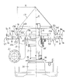
- FIG. 1 is a side sectional view of a vertical powder and particle feeder to which the gas feeding device is applied.
- a bottom plate 1 ' is fixed on a machine frame 30 with its flange 30', an outer cylinder 1 is erected on the bottom plate 1 ', and a lower end flange 1b of the outer cylinder 1 is attached to the bottom plate 1'.
- the granular material supply case 31 is formed by the bottom plate 1 ′ and the outer cylinder 1.
- An inner cylinder 2 concentric with the outer cylinder 1 is disposed on the bottom plate 1 ′ in the outer cylinder 1, and the powder material 3 is placed between the lower end 2 ′ of the inner cylinder 2 and the upper surface 1 a of the bottom plate 1 ′.
- the donut-shaped upper end opening 1 ′′ of the outer cylinder 1 is supported by supporting the donut-shaped lid 4 provided on the outer periphery of the inner cylinder 2 on the upper end of the outer cylinder 1 with the discharge gap t1 interposed therebetween. It closes and holds the powder discharge gap t1, forms an annular passage 5 of the powder raw material between the inner and outer cylinders 1, 2, and the powder raw material on the bottom plate 1 'in the passage 5
- the discharge port 6 is formed as an opening.
- a central opening 1a ′ is opened at the center of the bottom plate 1 ′ (see FIG. 2), and an upright rotating shaft 7 of the rotation center axis C is projected through the central opening 1a ′, as shown in FIG.
- the boss 15 having the rotation center axis C in common is connected to the upper end of the upright rotation shaft 7, and the conical cap 13 having the rotation center axis C in common is connected and fixed on the boss 15.
- annular boss disk 15a having a radius R is fixed to the outer periphery of the lower end of the boss 15 with the rotation center axis C as a common center.
- the boss disk 15a has a gap t2 of several tens of millimeters (for example, 40 mm) from the upper surface 1a of the bottom plate 1 ′, and the gap between the lower surface of the boss disk 15a and the upper surface 1a of the bottom plate 1 ′.
- An annular space (annular space) S having a radius t and a radius t2 is formed.
- the outer periphery of the boss disk 15a and the outer periphery of the lower end of the cap 13 are closed by an annular cone 16.
- the boss 15 and the boss disk 15a are referred to as a boss portion.
- the boss portion can be constituted by the boss 15 and the boss disk 15 a provided on the outer periphery of the lower end portion of the boss 15.
- An annular space S is formed between the upper surface 1a of the bottom plate 1 'and the lower surface of the boss part.
- the base portion of the rotary blade 8 is disposed along the upper surface 1a of the bottom plate 1 ′ with a gap t3 (for example, the same 40 mm as the gap t2) from the bottom plate 1a. 8b is fixed. That is, the base 8b of the rotary blade 8 is provided on the outer periphery of the boss disk 15a.
- the rotary blade 8 is composed of four spokes 8 a from the base portion 8 b toward the inner periphery of the outer cylinder 1, and the tip portion rotates along the inner periphery of the outer cylinder 1.
- a ring (tubular outer edge) 9 is provided.
- the rotating wheel 9 is provided with twelve inwardly rotating blades 10 toward the inner cylinder 2 at the same height as the spoke 8a.
- a first supply port (opening) 20 is provided in the bottom plate 1 'near the outer periphery of the space S, and the first supply
- the front end of the supply pipe 19 is connected and fixed to the mouth 20 from the lower surface side of the bottom plate 1 ′, and a connection flange 21 is provided at the other end of the supply pipe 19.
- the tip 19a of the supply pipe 19 protrudes slightly above the upper surface 1a of the bottom plate 1 '.
- the protrusion width of the tip 19a from the upper surface 1a of the bottom plate 1 ' is, for example, a height position that is 1 ⁇ 2 of the vertical gap t2 of the annular space S.
- an air supply machine (not shown) is connected to the connection flange 21, a gas (for example, dry air) is blown from the air supply machine into the supply pipe 19, and the dry air is passed through the supply pipe 19. It is configured so that it can be fed into the annular space S on the lower surface of the boss disk 15a.
- a gas for example, dry air
- the first supply port (opening) 20 has a symmetrical position (rotation center axis C) of the bottom plate 1 ′ along the diameter line L in the annular space S (annular dam plate 22).
- the other supply pipe 19 is connected to the other first supply port 20 from the lower side of the bottom plate 1 ′, and the two supply pipes 19 are provided. , 19 can be supplied with gas (for example, dry air) (see FIG. 1).
- the projecting width of the tip 19a of the other supply pipe 19 from the upper surface 1a of the bottom plate 1 ' is also set to a height position that is 1 ⁇ 2 of the vertical gap t2 of the annular space S.
- annular weir plate 22 On the lower surface near the outer peripheral edge of the boss disk 15a, an annular weir plate 22 having a radius R substantially the same as the radius R of the annular space S and having the rotation center axis C as a common center has an upper end surface 22a. The drooping is fixed.
- annular dam plate 22 is shown in FIG.
- a recess 22b is provided on the upper edge of the annular weir plate 22 at regular intervals over the entire circumference, and is thus fixed to the lower surface of the boss disk 15a with the upper end surface 22a.
- twelve upper slits 23 are provided in the annular weir plate 22.
- the gas (dry air) fed from the supply pipe 19 into the annular space S is sent from the upper slits 23 of the annular dam plate 22 to the annular dam plate as shown in FIG.
- the air is blown in the radial direction (arrow B direction) around 22 and is blown in the radial direction (arrow B direction) from the entire circumference of the annular dam plate 22 through the lower slit 24.
- the upper surface of the bottom plate 1 ' Air is sent to the entire la, that is, the entire top surface 1a of the bottom plate 1 'in the inner cylinder 2 and the entire top surface 1a of the bottom plate 1' of the annular passage 5.
- the upper slit 23 and the lower slit 24 of the annular dam plate 22 constitute a slit.
- a second supply port (opening) 34 is also provided on the plate surface of the donut-shaped lid 4, a supply pipe 25 is connected to the second supply port 34, and the supply pipe
- an air supply device (not shown) is connected to the flange 33 of the 25, and dry air can be supplied as a gas from the donut-shaped lid 4 through the supply pipe 25 into the annular passage 5.
- the supply pipe 25 is provided, for example, at three positions on the upper surface of the donut-shaped lid 4 through a certain angle in the circumferential direction (see FIG. 4).
- a cylindrical hopper (straight hopper) 11 having the same diameter as that of the inner cylinder 2 is connected to the upper part of the inner cylinder 2 by a flange 32, and a powder material raw material inlet is provided at the center of the upper surface 11 a ′ of the cylindrical hopper 11. An opening 11a is formed.
- the granular material 3 is supplied into the cylindrical hopper 11 from the material charging port 11a, whereby a predetermined rest is provided from the granular material discharge gap t1 at the lower end of the inner cylinder 2 toward the annular passage 5.
- a predetermined rest is provided from the granular material discharge gap t1 at the lower end of the inner cylinder 2 toward the annular passage 5.
- the upright rotating shaft 7 is connected to a drive motor 12 via a speed reducer 14, and the rotary blade 8 is rotationally driven in the direction of arrow A by the drive motor 12.
- a rotary valve 27 is connected to the discharge port 6 via a flange 26 so as to suppress the outflow of the dry air from the discharge port 6 so that only the dried granular material 3 can be discharged downward. It is composed.
- an opening 11b is provided in the upper surface 11a 'of the cylindrical hopper 11, and an exhaust fan 29 is provided in the opening 11b through an exhaust pipe 28, thereby forcibly exhausting the dry air fed into the powder and particle feeder. Configure to be able to.
- the granular material 3 such as pellets is charged into the cylindrical hopper 11 from the granular material inlet 11a to the upper end level (see the two-dot chain line in FIG. 1). Then, the granular material 3 flows out from the inner cylinder 2 into the annular passage 5 at an angle of repose q. At this time, the granular material is densely stored in the cylindrical hopper 11 and the inner cylinder 2, and the granular material 3 is also densely present on the upper surface of the rotary blade 8.
- the lower surface 8c side of 8 (see FIG. 2) is in a sparse state in which the density of the granular material 3 is small compared to other regions.
- the granular material 3 in the annular passage 5 is swelled on the upper surface of the rotary blade 8 by the rotation of the rotary blade 8 in the direction of arrow A. Since it is carried in the direction of arrow A, the density of the granular material 3 is sparse on the lower surface 8c side of the rotary blade 8 from the base 8b portion to the tip portion direction even during the conveyance.
- the air supply device is driven to feed dry air from the first supply ports 20, 20 into the annular space S through the two supply pipes 19, 19. At the same time, dry air is fed into the annular passage 5 from the second supply ports 34, 34, 34 through the three supply pipes 25, 25, 25 of the donut-shaped lid 4.
- the dry air (gas) flowing out from the first supply port 20 is once dammed in the annular space S constituted by the annular dam plate 22, and then at a narrow outlet in the annular space S. It flows out in a radial direction (arrow B direction) from a certain upper slit 23 and lower slit 24. Accordingly, the pressure of the gas in the annular space S is increased to increase the flow velocity of the gas flowing out from the slits 23 and 24, thereby efficiently radiating the gas to the entire upper surface 1a of the bottom plate 1 'in the radial direction.
- the powder raw material 3 can be uniformly dried and the like. Furthermore, since the dry air supplied to the upper surface 1a of the bottom plate 1 'rises through the cylindrical hopper 11 and is exhausted from the exhaust pipe 28, the powder material in the cylindrical hopper 11 can be dried. it can.
- these dry airs are all fed toward the tip of the rotary blade 8 through the lower surface 8 c side of the rotary blade 8, and The air is blown from both edge sides of the spoke 8a in the direction along the bottom plate 1 ′ upper surface 1a (in the direction of arrow D in FIG. 4).
- the dry air passes through the lower surface 8 c side of each rotary blade 8 and is fed from the left and right side edges of the rotary blade 8 to the granular material in the inner cylinder 2 and the annular passage 5. Therefore, the dry air (gas) is sufficiently supplied also to the lower surface 8c side of the rotating blade 8 having a low density of the granular material raw material, and the entire granular raw material 3 can be evenly and sufficiently dried.
- the dry air has a bottom plate that radiates from the bottom of the boss disk 15a (boss portion) on the rotation center axis C side on the base 8b side of the rotary blade 8, that is, the lower side of the rotation blade 8 toward the outer periphery. Since it can be fed to the entire upper surface 1a of 1 ', it can be sufficiently supplied to the granular material 3 in the vicinity of the upright rotating shaft 7 at the lower center of the hopper, which has not been able to supply dry air sufficiently, Thereby, the granular material raw material 3 can be dried uniformly.
- the granular material 3 supplied into the cylindrical hopper 11 flows out into the annular passage 5 at an angle of repose q, and the granular raw material 3 in the annular passage 5 is rotated as described above. It is conveyed by the blade 8 and continuously supplied and discharged downward from the discharge port 6. And in the continuous supply state of this granular material raw material, gas, such as dry air, is sent from the annular space S below the boss
- the powder raw material 3 can be continuously dried.
- the present invention can continuously feed a gas such as dry air in the radial direction from the vicinity of the central portion (boss portion) of the upright rotating shaft 7 of the rotary blade 8.
- a gas such as dry air in the radial direction from the vicinity of the central portion (boss portion) of the upright rotating shaft 7 of the rotary blade 8.
- the gas can be fed from the lower surface 8c near the base 8b of the rotary blade 8 to the outer side (the direction of the outer cylinder 1), the lower surface of the rotary blade 8 having a relatively sparse powder density.
- the gas can be sufficiently fed also to the 8c side, and the gas can be uniformly dried by feeding the gas to the whole powder material 3 on the bottom plate 1 ′.
- the gas can also be supplied from the annular passage 5 which is the outer periphery of the powder supply unit.
- the powder material 3 can be dried more efficiently.
- the exhaust fan 29 in the cylindrical hopper 11 provided as a hopper for charging the powder material the gas fed into the powder supply machine can be forcibly exhausted, and more efficiently.
- the whole powder material can be dried.
- the present invention describes the case where dry air is supplied to the granular material as a gas for drying the granular material, but the present invention is not limited to this. Therefore, it can be used in the case of drying and dehumidifying the granular raw material by the dry air, and when supplying the steam as a gas to humidify the granular raw material, the gas containing the drug Can be used for various purposes, such as when fumigating powder raw materials.
- the powder raw material is not limited to so-called fine powder-like objects and fine particles, but various powder particles such as relatively heavy pellets, synthetic resin particles such as waste plastics, etc. Body materials can be used.
- 35 is an outflow prevention plate for the granular material
- 36 in FIG. 2 is a draining plate.
- the gas feeding device in the powder and particle feeder according to the present invention can be widely used as a continuous drying device, a humidifying device, a fumigation device and the like for various powder materials such as pellets.
Landscapes
- Engineering & Computer Science (AREA)
- Mechanical Engineering (AREA)
- General Engineering & Computer Science (AREA)
- Drying Of Solid Materials (AREA)
- Filling Or Emptying Of Bunkers, Hoppers, And Tanks (AREA)
Description
第1に、底板に外筒を立設して粉粒体供給ケースとし、上記底板の上方に粉粒体排出間隙を介して上下開口の内筒を設け、上記内筒の外側面と上記外筒の上端とをドーナツ形蓋体によって同心に接続して上記内外筒間に円環状通路を形成し、上記底板の中心に直立回転軸を設け、該直立回転軸上部にボス部を設け、このボス部の外周に上記底板に沿う複数の回転羽根を、上記底板から一定の距離を以って設けると共に、上記回転羽根の先端を、上記外筒の内周面に沿って設けた回転輪に接続し、かつ上記円環状通路の上記底板に排出口を開口し、上記粉粒体排出間隙から所定の安息角にて上記円環状通路に拡散した粉粒体原料を、上記回転羽根により上記排出口に移送する粉粒体供給機における気体送給装置において、上記ボス部の下面における上記底板に気体の第一の供給口を設けて、上記底板上面と上記ボス部下面間の空間に気体を送給し得るように構成し、上記第一の供給口より外側の上記ボス部下面に環状堰板を上記内外筒に同心に形成し、上記第一の供給口から上記空間内に送給された気体を上記環状堰板に沿って設けられたスリットを介して、放射方向に送給し得るように構成したものであることを特徴とする粉粒体供給機における気体送給装置により構成される。
図1に示すように、機枠30上にそのフランジ30’を以って底板1’を固定し、該底板1’に外筒1を立設し、上記外筒1の下端フランジ1bを上記機枠30の上記フランジ30’に固定することにより、上記底板1’及び上記外筒1により粉粒体供給ケース31を形成する。
Claims (7)
- 底板に外筒を立設して粉粒体供給ケースとし、上記底板の上方に粉粒体排出間隙を介して上下開口の内筒を設け、上記内筒の外側面と上記外筒の上端とをドーナツ形蓋体によって同心に接続して上記内外筒間に円環状通路を形成し、
上記底板の中心に直立回転軸を設け、該直立回転軸上部にボス部を設け、このボス部の外周に上記底板に沿う複数の回転羽根を、上記底板から一定の距離を以って設けると共に、上記回転羽根の先端を、上記外筒の内周面に沿って設けた回転輪に接続し、
かつ上記円環状通路の上記底板に排出口を開口し、上記粉粒体排出間隙から所定の安息角にて上記円環状通路に拡散した粉粒体原料を、上記回転羽根により上記排出口に移送する粉粒体供給機における気体送給装置において、
上記ボス部の下面における上記底板に気体の第一の供給口を設けて、上記底板上面と上記ボス部下面間の空間に気体を送給し得るように構成し、
上記第一の供給口より外側の上記ボス部下面に環状堰板を上記内外筒に同心に形成し、上記第一の供給口から上記空間内に送給された気体を上記環状堰板に沿って設けられたスリットを介して、放射方向に送給し得るように構成したものであることを特徴とする粉粒体供給機における気体送給装置。 - 上記環状堰板に設けられた上記スリットは、上記ボス部の外周に設けられた上記回転羽根の下面側に位置するものであることを特徴とする請求項1記載の粉粒体供給機における気体送給装置。
- 上記環状堰板の上記スリットは、上記ボス部下面と上記環状堰板との間の上部スリットと、上記環状堰板の下端と上記底板上面との間の下部スリットにより構成されたものであることを特徴とする請求項1又は2記載の粉粒体供給機における気体送給装置。
- 上記第一の供給口は上記直立回転軸を中心とする上記ボス部下面の上記環状堰板の直径線に沿った対称位置に各々設けられているものであることを特徴とする請求項1~3の何れかに記載の粉粒体供給機における気体送給装置。
- 上記ドーナツ形蓋体に第二の供給口を設け、上記ドーナツ形蓋体の上記第二の供給口から気体を上記円環状通路内に送給するものであることを特徴とする請求項1~4の何れかに記載の粉粒体供給機における気体送給装置。
- 上記内筒上端に粉粒体原料投入用のホッパーを接続固定し、該ホッパーに粉粒体供給機内に送給された気体の排気ファンを設けたものであることを特徴とする請求項1~5の何れかに記載の粉粒体供給機における気体送給装置。
- 上記粉粒体原料の上記排出口にロータリーバルブを設けたものであることを特徴とする請求項1~6の何れかに記載の粉粒体供給機における気体送給装置。
Priority Applications (6)
| Application Number | Priority Date | Filing Date | Title |
|---|---|---|---|
| KR1020147034881A KR20150011381A (ko) | 2012-06-08 | 2012-11-06 | 분립체 공급기에서의 기체 송급 장치 |
| CN201280073831.0A CN104350346B (zh) | 2012-06-08 | 2012-11-06 | 粉粒体供给机中的气体送给装置 |
| US14/401,047 US9441882B2 (en) | 2012-06-08 | 2012-11-06 | Gas feeding apparatus for powder and granular material feeder |
| KR1020177021917A KR101907813B1 (ko) | 2012-06-08 | 2012-11-06 | 분립체 공급기에서의 기체 송급 장치 |
| AU2012382164A AU2012382164B2 (en) | 2012-06-08 | 2012-11-06 | Gas feeding apparatus for powder and granular material feeder |
| EP12878400.6A EP2860480B1 (en) | 2012-06-08 | 2012-11-06 | Gas feed device in powder/granular material feeder |
Applications Claiming Priority (2)
| Application Number | Priority Date | Filing Date | Title |
|---|---|---|---|
| JP2012130489A JP5830436B2 (ja) | 2012-06-08 | 2012-06-08 | 粉粒体供給機における気体送給装置 |
| JP2012-130489 | 2012-06-08 |
Publications (1)
| Publication Number | Publication Date |
|---|---|
| WO2013183179A1 true WO2013183179A1 (ja) | 2013-12-12 |
Family
ID=49711592
Family Applications (1)
| Application Number | Title | Priority Date | Filing Date |
|---|---|---|---|
| PCT/JP2012/078699 Ceased WO2013183179A1 (ja) | 2012-06-08 | 2012-11-06 | 粉粒体供給機における気体送給装置 |
Country Status (7)
| Country | Link |
|---|---|
| US (1) | US9441882B2 (ja) |
| EP (1) | EP2860480B1 (ja) |
| JP (1) | JP5830436B2 (ja) |
| KR (2) | KR20150011381A (ja) |
| CN (1) | CN104350346B (ja) |
| AU (1) | AU2012382164B2 (ja) |
| WO (1) | WO2013183179A1 (ja) |
Families Citing this family (12)
| Publication number | Priority date | Publication date | Assignee | Title |
|---|---|---|---|---|
| JP5830436B2 (ja) * | 2012-06-08 | 2015-12-09 | 株式会社ヨシカワ | 粉粒体供給機における気体送給装置 |
| JP5856037B2 (ja) * | 2012-10-25 | 2016-02-09 | 株式会社ヨシカワ | 定量フィーダー |
| US20160217974A1 (en) * | 2015-01-28 | 2016-07-28 | Stephen J. Motosko | Apparatus for plasma treating |
| JP2016166081A (ja) * | 2015-03-10 | 2016-09-15 | オヤマダエンジニアリング株式会社 | 粉粒体供給装置及びこれを用いたボイラシステム |
| JP2017003146A (ja) * | 2015-06-05 | 2017-01-05 | 研機株式会社 | 乾燥装置 |
| JP6192701B2 (ja) | 2015-11-26 | 2017-09-06 | 株式会社ヨシカワ | 排出シュートにおける結露防止装置及び粉粒体供給装置 |
| CN107869899A (zh) * | 2017-12-11 | 2018-04-03 | 新昌县康宝药店有限公司 | 一种中药药渣再加工设备 |
| EP4166878A1 (en) * | 2018-06-28 | 2023-04-19 | GEA Process Engineering A/S | A dryer and a method for drying a liquid feed into a powder |
| JP1632317S (ja) * | 2018-10-18 | 2019-05-27 | ||
| US11483977B2 (en) * | 2020-01-06 | 2022-11-01 | Deere & Company | Grain loss prevention system using air blowers |
| JP7650489B2 (ja) * | 2021-03-16 | 2025-03-25 | 株式会社カワタ | 粉粒体処理装置および粉粒体処理方法 |
| CN113566527B (zh) * | 2021-07-06 | 2022-09-13 | 无锡市贝斯尔精密机械有限公司 | 一种生物质能颗粒原料风干装置 |
Citations (7)
| Publication number | Priority date | Publication date | Assignee | Title |
|---|---|---|---|---|
| JPS53128876A (en) * | 1977-04-13 | 1978-11-10 | Mitsui Miike Mach Co Ltd | Method for separating out pulverulent body of silo and its device |
| JPH0335935U (ja) * | 1989-08-14 | 1991-04-08 | ||
| JPH0740643U (ja) * | 1993-12-28 | 1995-07-21 | 修 吉川 | 粉粒体フィーダにおける粉粒体の残留防止装置 |
| JP2001278453A (ja) | 2000-03-30 | 2001-10-10 | Yoshikawa:Kk | 粉粒体供給機 |
| JP2003004377A (ja) | 2001-06-19 | 2003-01-08 | Aishu Sangyo:Kk | 粉粒体乾燥装置及び粉粒体乾燥設備 |
| JP2003194465A (ja) * | 2001-12-27 | 2003-07-09 | Idemitsu Petrochem Co Ltd | 粉粒体の乾燥方法 |
| JP2004051258A (ja) * | 2002-07-17 | 2004-02-19 | Mitsubishi Heavy Ind Ltd | 粉粒体供給装置 |
Family Cites Families (19)
| Publication number | Priority date | Publication date | Assignee | Title |
|---|---|---|---|---|
| US4900200A (en) * | 1988-06-22 | 1990-02-13 | Matsui Manufacturing Co., Ltd. | Method for transporting powdered or granular materials by pneumatic force with a transport pipe of smaller diameter relative to particale size |
| US5944513A (en) * | 1992-12-28 | 1999-08-31 | Kawasaki Jukogyo Kabushiki Kaisha | Apparatus for manufacturing cement clinker |
| JP3143309B2 (ja) | 1993-06-04 | 2001-03-07 | ホソカワミクロン株式会社 | 粉粒体処理装置 |
| US6079118A (en) * | 1998-01-23 | 2000-06-27 | Kiyokawa; Shin | Continuous drying system |
| JP3773675B2 (ja) * | 1998-10-28 | 2006-05-10 | 株式会社松井製作所 | 粉粒体材料の真空式自動連続除湿乾燥装置 |
| KR100392486B1 (ko) * | 1998-11-02 | 2003-07-28 | 가와사키 쥬코교 가부시키가이샤 | 다챔버형 유동층분급장치 |
| US6092301A (en) * | 1998-11-13 | 2000-07-25 | Komanowsky; Michael | Microwave drying of hides under vacuum in tanning equipment |
| JP2001149770A (ja) | 1999-12-01 | 2001-06-05 | Hosokawa Micron Corp | 粉粒体処理装置 |
| JP4048465B2 (ja) | 2000-10-13 | 2008-02-20 | 株式会社奈良機械製作所 | 粉粒体の流動処理装置 |
| EP1440729B9 (en) * | 2001-10-29 | 2013-04-03 | Nara Machinery Co., Ltd. | Device for treating powder particles by rotary flow |
| JP2004144313A (ja) * | 2002-10-21 | 2004-05-20 | Matsui Mfg Co | 粉粒体材料の乾燥装置 |
| JP2004198066A (ja) * | 2002-12-20 | 2004-07-15 | Matsui Mfg Co | 粉粒体材料の乾燥貯留装置及び粉粒体材料の供給システム |
| DE10344845A1 (de) * | 2003-09-26 | 2005-04-14 | Basf Ag | Vorrichtung zum Mischen, Trocknen und Beschichten von pulvrigem, körnigem oder geformtem Schüttgut in einem Fließbett und Verfahren zur Herstellung von Trägerkatalysatoren unter Verwendung einer solchen Vorrichtung |
| DE202005003791U1 (de) * | 2005-02-28 | 2006-07-06 | Hüttlin, Herbert, Dr. h.c. | Apparatur zur Behandlung von partikelförmigem Gut |
| US7908765B2 (en) * | 2006-12-22 | 2011-03-22 | Collette Nv | Continuous granulating and drying apparatus |
| JP2008264756A (ja) * | 2007-03-23 | 2008-11-06 | Kunitomo Kankyo Plant:Kk | 有機廃棄物の処理装置及び処理方法,該処理方法によって得られる有機資材 |
| US9750901B2 (en) * | 2011-06-13 | 2017-09-05 | Shanghai Xiuxin Chenpon Pharmaceutical Technology Co., Ltd. | Dry powder drug-dosing device |
| JP5830436B2 (ja) * | 2012-06-08 | 2015-12-09 | 株式会社ヨシカワ | 粉粒体供給機における気体送給装置 |
| US10094615B2 (en) * | 2014-05-28 | 2018-10-09 | Gregory Howard O'Gary | Bin system and method of regulating particulate flow from bins |
-
2012
- 2012-06-08 JP JP2012130489A patent/JP5830436B2/ja active Active
- 2012-11-06 CN CN201280073831.0A patent/CN104350346B/zh active Active
- 2012-11-06 KR KR1020147034881A patent/KR20150011381A/ko not_active Ceased
- 2012-11-06 EP EP12878400.6A patent/EP2860480B1/en active Active
- 2012-11-06 AU AU2012382164A patent/AU2012382164B2/en active Active
- 2012-11-06 KR KR1020177021917A patent/KR101907813B1/ko active Active
- 2012-11-06 WO PCT/JP2012/078699 patent/WO2013183179A1/ja not_active Ceased
- 2012-11-06 US US14/401,047 patent/US9441882B2/en active Active
Patent Citations (7)
| Publication number | Priority date | Publication date | Assignee | Title |
|---|---|---|---|---|
| JPS53128876A (en) * | 1977-04-13 | 1978-11-10 | Mitsui Miike Mach Co Ltd | Method for separating out pulverulent body of silo and its device |
| JPH0335935U (ja) * | 1989-08-14 | 1991-04-08 | ||
| JPH0740643U (ja) * | 1993-12-28 | 1995-07-21 | 修 吉川 | 粉粒体フィーダにおける粉粒体の残留防止装置 |
| JP2001278453A (ja) | 2000-03-30 | 2001-10-10 | Yoshikawa:Kk | 粉粒体供給機 |
| JP2003004377A (ja) | 2001-06-19 | 2003-01-08 | Aishu Sangyo:Kk | 粉粒体乾燥装置及び粉粒体乾燥設備 |
| JP2003194465A (ja) * | 2001-12-27 | 2003-07-09 | Idemitsu Petrochem Co Ltd | 粉粒体の乾燥方法 |
| JP2004051258A (ja) * | 2002-07-17 | 2004-02-19 | Mitsubishi Heavy Ind Ltd | 粉粒体供給装置 |
Non-Patent Citations (1)
| Title |
|---|
| See also references of EP2860480A4 |
Also Published As
| Publication number | Publication date |
|---|---|
| KR20150011381A (ko) | 2015-01-30 |
| US9441882B2 (en) | 2016-09-13 |
| EP2860480B1 (en) | 2018-01-10 |
| EP2860480A1 (en) | 2015-04-15 |
| JP2013253756A (ja) | 2013-12-19 |
| KR20170094005A (ko) | 2017-08-16 |
| AU2012382164A1 (en) | 2014-11-27 |
| CN104350346B (zh) | 2016-01-27 |
| CN104350346A (zh) | 2015-02-11 |
| US20150143710A1 (en) | 2015-05-28 |
| JP5830436B2 (ja) | 2015-12-09 |
| KR101907813B1 (ko) | 2018-10-12 |
| EP2860480A4 (en) | 2016-04-06 |
| AU2012382164B2 (en) | 2015-11-19 |
Similar Documents
| Publication | Publication Date | Title |
|---|---|---|
| JP5830436B2 (ja) | 粉粒体供給機における気体送給装置 | |
| JP4243022B2 (ja) | 流し込み可能な製品を乾燥させるための装置及びこの装置を使用するための方法 | |
| US3898745A (en) | Drying apparatus for concentrating solutions | |
| CN110044138B (zh) | 振动干燥装置 | |
| CN105689075B (zh) | 用于加工原料的装置和方法 | |
| JP2010517831A5 (ja) | ||
| JP6383679B2 (ja) | 触媒充填装置および触媒充填方法 | |
| RU2010118462A (ru) | Способ и спиральное устройство для контакта газа с твердым веществом | |
| JP3947913B2 (ja) | 穀物の衝撃式粉砕装置 | |
| CN105728320B (zh) | 一种成型颗粒的干燥筛选装置 | |
| CN110935626B (zh) | 一种化工用新型化工物料筛选机 | |
| JPH0747261A (ja) | 粉粒体処理装置 | |
| CA2902531C (en) | Device for comminution of process feed material with upstream sifting | |
| JP4753387B2 (ja) | 気流分級装置 | |
| JP5000532B2 (ja) | 少なくとも1種の粒状材料を容器内へ分配する装置、充填装置、およびそのような装置を用いた充填方法 | |
| CN107413281A (zh) | 一种高转速湿法剪切造粒机 | |
| JP3805453B2 (ja) | 粉粒体処理装置およびこれを用いた粉粒体処理方法 | |
| FI81026C (fi) | Sfaeronizer. | |
| CN103341421B (zh) | 喷料装置 | |
| JP2010126343A (ja) | 粉粒体供給機における材料移送装置 | |
| CN104549691B (zh) | 粘结橡胶颗粒动态筛选打碎装置及打碎输料方法 | |
| US20040255981A1 (en) | Process and apparatus for treating a particulate material | |
| RU2016114696A (ru) | Устройство измельчения твердых материалов | |
| JPH0691151A (ja) | 流動層利用の造粒装置 | |
| TW200806941A (en) | Dispersible gas flow bottom tub of a granulating machine |
Legal Events
| Date | Code | Title | Description |
|---|---|---|---|
| 121 | Ep: the epo has been informed by wipo that ep was designated in this application |
Ref document number: 12878400 Country of ref document: EP Kind code of ref document: A1 |
|
| WWE | Wipo information: entry into national phase |
Ref document number: 14401047 Country of ref document: US |
|
| ENP | Entry into the national phase |
Ref document number: 2012382164 Country of ref document: AU Date of ref document: 20121106 Kind code of ref document: A |
|
| NENP | Non-entry into the national phase |
Ref country code: DE |
|
| WWE | Wipo information: entry into national phase |
Ref document number: 2012878400 Country of ref document: EP |
|
| ENP | Entry into the national phase |
Ref document number: 20147034881 Country of ref document: KR Kind code of ref document: A |