WO2013183192A1 - Dispositif de terminal mobile - Google Patents
Dispositif de terminal mobile Download PDFInfo
- Publication number
- WO2013183192A1 WO2013183192A1 PCT/JP2013/000051 JP2013000051W WO2013183192A1 WO 2013183192 A1 WO2013183192 A1 WO 2013183192A1 JP 2013000051 W JP2013000051 W JP 2013000051W WO 2013183192 A1 WO2013183192 A1 WO 2013183192A1
- Authority
- WO
- WIPO (PCT)
- Prior art keywords
- housing
- terminal device
- main body
- mobile terminal
- longitudinal direction
- Prior art date
- Legal status (The legal status is an assumption and is not a legal conclusion. Google has not performed a legal analysis and makes no representation as to the accuracy of the status listed.)
- Ceased
Links
Images





Classifications
-
- G—PHYSICS
- G06—COMPUTING OR CALCULATING; COUNTING
- G06F—ELECTRIC DIGITAL DATA PROCESSING
- G06F1/00—Details not covered by groups G06F3/00 - G06F13/00 and G06F21/00
- G06F1/16—Constructional details or arrangements
- G06F1/1613—Constructional details or arrangements for portable computers
- G06F1/1633—Constructional details or arrangements of portable computers not specific to the type of enclosures covered by groups G06F1/1615 - G06F1/1626
- G06F1/1656—Details related to functional adaptations of the enclosure, e.g. to provide protection against EMI, shock, water, or to host detachable peripherals like a mouse or removable expansions units like PCMCIA cards, or to provide access to internal components for maintenance or to removable storage supports like CDs or DVDs, or to mechanically mount accessories
-
- G—PHYSICS
- G06—COMPUTING OR CALCULATING; COUNTING
- G06F—ELECTRIC DIGITAL DATA PROCESSING
- G06F1/00—Details not covered by groups G06F3/00 - G06F13/00 and G06F21/00
- G06F1/16—Constructional details or arrangements
- G06F1/1613—Constructional details or arrangements for portable computers
- G06F1/1626—Constructional details or arrangements for portable computers with a single-body enclosure integrating a flat display, e.g. Personal Digital Assistants [PDAs]
-
- H—ELECTRICITY
- H04—ELECTRIC COMMUNICATION TECHNIQUE
- H04M—TELEPHONIC COMMUNICATION
- H04M1/00—Substation equipment, e.g. for use by subscribers
- H04M1/02—Constructional features of telephone sets
- H04M1/0202—Portable telephone sets, e.g. cordless phones, mobile phones or bar type handsets
Definitions
- the present invention relates to a mobile terminal device, and more particularly to a mobile terminal device using a thin casing.
- a resin material is used for the casing of the mobile terminal device in view of ease of processing and cost reduction.
- GL resin olefin vinyl alcohol copolymer
- Patent Document 1 olefin vinyl alcohol copolymer
- an object of the present invention is to provide a mobile terminal device capable of suppressing warping of a casing.
- a mobile terminal device is a mobile terminal device including a housing, and the housing includes a housing main body and a side wall provided at a peripheral edge of the housing main body.
- the housing body includes a first member extending in a longitudinal direction of the housing body and a first end that is one end in the longitudinal direction of the housing body. And a second member that extends to the second end, which is the other end in the longitudinal direction, and has a thermal contraction rate smaller than that of the first member.
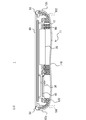
- FIG. 3 is a cross-sectional view taken along the line AA of the mobile terminal device shown in FIG.
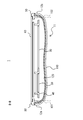
- FIG. 3 is a cross-sectional view taken along the line BB of the mobile terminal device shown in FIG.
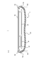
- FIG. 3 is a cross-sectional view taken along the line CC of the mobile terminal device shown in FIG. FIG.
- FIG. 3 is a cross-sectional view taken along DD of the mobile terminal device shown in FIG. 2.
- FIG. 3 is a cross-sectional view taken along line EE of the mobile terminal device shown in FIG. It is a rear view of the housing
- FIG. 1 is an exploded perspective view showing an example of a mobile terminal device 1 according to the present embodiment.
- main components such as the battery 20, the substrate 30, and the frame member 40 are accommodated in a space formed by joining the housing 10 and the display unit 60.
- the mobile terminal device 1 according to the present embodiment is, for example, a smartphone, a tablet-type mobile terminal device, a mobile phone, a game machine, an electronic book terminal, or the like.
- the housing 10 is configured to accommodate the battery 20, the substrate 30, and the frame member 40 inside the housing 10.
- the housing 10 includes a housing body 11, a side wall 12, and a fixing unit 13.
- the housing main body 11 is a back surface portion of the mobile terminal device 1.
- the side wall 12 is a wall provided at the peripheral edge of the housing body 11.
- a plurality of fixing portions 13 for fixing the battery 20 and the frame member 40 to the housing 10 are provided on the inner surface of the housing 10.
- the fixing portion 13 is provided at a location corresponding to a fixing position (an attachment hole (not shown)) of the battery 20 and the frame member 40.
- the fixing portion 13 is provided inside the side wall portion 12.
- Each fixing portion 13 is formed with a mounting hole. In the example shown in FIG. 1, ten fixing portions 13 are provided on the inner surface of the housing 10.
- the battery 20 is, for example, a lithium ion secondary battery.
- a plurality of mounting holes for fixing the battery 20 to the housing 10 using screws or the like are formed at positions corresponding to the fixing portion 13 of the housing 10.
- two attachment holes are formed at both ends in the longitudinal direction of the battery 20.
- the substrate 30 is provided with circuit elements.
- the circuit element is, for example, an integrated circuit device such as a processor, a memory, or a communication module for driving the mobile terminal device 1, an image sensor for a camera, or the like.
- the substrate 30 is fixed to the frame member 40 using screws or the like.
- the frame member 40 is a member for holding the battery 20 and the substrate 30. Since the frame member 40 requires a certain level of strength, it is preferably formed of a metal material. Examples of the material used for the frame member 40 include magnesium alloy, aluminum, and stainless steel. In view of weight reduction of the mobile terminal device 1, it is preferable to use a magnesium alloy.
- the frame member 40 has an opening 41 at a position corresponding to the position where the battery 20 is attached. That is, the frame member 40 has the opening 41 at a position facing the upper surface of the battery 20. By providing the opening 41 in this way, a part of the battery 20 can be provided inside the frame member 40, and the space inside the housing can be used effectively.
- the frame member 40 has a plurality of mounting holes (not shown) for fixing the battery 20 to the frame member 40 using screws or the like. Thereby, for example, the battery 20 is fixed to the frame member 40 from the side where the housing 10 is provided using screws or the like.
- the frame member 40 has an opening 42 at a location corresponding to the position where the substrate 30 is attached. By providing the opening 42 in this manner, it is possible to prevent the frame member 40 and the circuit element from interfering even when the height of the circuit element provided on the substrate 30 is high.
- the frame member 40 is formed with a plurality of mounting holes (not shown) for fixing the substrate 30 to the frame member 40 using screws or the like. Thereby, the board
- the frame member 40 has a plurality of mounting holes (not shown) for fixing the frame member 40 to the housing 10 with screws or the like at positions corresponding to the fixing portions 13 of the housing 10. Yes.
- the display unit 60 is attached to a front molding 50 (fitting member) disposed on the side wall 12 of the housing 10.
- the display unit 60 includes a display panel 61 and a touch panel 62 provided on the surface side of the display panel 61.
- a panel made of glass or plastic that does not have a touch panel function may be provided on the surface side of the display panel 61 instead of the touch panel 62.
- the display panel 61 is, for example, a liquid crystal panel or an organic EL (Electro Luminescence) panel.
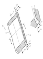
- FIG. 2 is a rear perspective view of the mobile terminal device 1 according to the present embodiment.
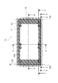
- FIG. 3 is a top view of the housing 10.
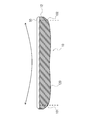
- FIG. 4 is a side view of the housing 10.
- FIG. 5 is a rear view of the housing 10.
- 6 is a cross-sectional view taken along line AA in FIG. 2 (or FIG. 3).
- FIG. 7 is a cross-sectional view taken along the line BB in FIG. 2 (or FIG. 3).
- FIG. 8 is a cross-sectional view taken along the line CC of FIG. 2 (or FIG. 3).
- FIG. 9 is a cross-sectional view taken along DD in FIG. 2 (or FIG. 3).
- 10 is a cross-sectional view taken along line EE of FIG. 2 (or FIG. 3).
- the housing 10 is configured to include a carbon composite material (carbon fiber reinforced plastic (CFRP: Carbon Fiber Reinforced Plastics)).
- CFRP Carbon Fiber Reinforced Plastics
- the carbon composite material is a composite material containing 50% by volume or more of carbon and containing an inorganic binder such as silica and alumina, a fiber, and the like. Carbon composite material has both high strength and lightness. Carbon composite materials have higher thermal conductivity than resin materials (plastic materials). Further, the carbon composite material (second member) has a smaller thermal shrinkage rate than the resin material (first member). That is, when the temperature changes from high temperature to low temperature, the resin material has a higher rate of volume change (shrinkage) than the carbon composite material.
- CFRP Carbon Fiber Reinforced Plastics
- the housing body 11 is a portion of the housing 10 that has a surface facing the display unit 60.
- the housing body 11 is a back surface portion of the housing 10.
- a portion sandwiched between broken lines in FIGS. 3 to 5 and FIGS. That is, the portion that intersects with the broken line is the end portion (first end portion 101 and second end portion 102) of the housing body 11.
- the side walls 12 a and 12 b are walls that are provided at the peripheral edge of the housing body 11 and support the display unit 60.
- the portions outside the broken lines in FIGS. 3 to 5 and FIGS. 7 to 10 are the side walls 12a and 12b.
- the side walls 12a and 12b are substantially orthogonal to the display unit 60, but need not be substantially orthogonal.
- the side walls 12a and 12b may be configured using a curved portion and a flat plate portion as shown in FIGS. 7 to 10, or may be configured using only the curved portion or only the flat plate portion. .
- the side walls 12a and 12b have been described above, the same applies to the side walls 12c and 12d (see FIG. 6) at both ends of the casing 10 in the short direction.
- the casing 10 of the mobile terminal device 1 has a portion formed using the carbon composite material 110 and a portion formed using the resin material 120 (shaded hatched portion).
- a resin material 120 is provided on the inner peripheral surface of the housing 10 at the peripheral portion of the housing body 11. More specifically, the resin material 120 extends in the longitudinal direction of the housing body 11, and extends from the first end 101 that is one end in the longitudinal direction of the housing body 11 to the longitudinal direction of the housing body 11. Extends to the second end 102, which is the other end. Further, the resin material 120 is disposed in contact with both ends of the casing body 11 in the short direction.
- the resin material 120 is disposed in contact with both end portions (first and second end portions 101 and 102) in the longitudinal direction of the housing body 11. For this reason, as shown in FIG. 3, the resin material 120 having a predetermined width is arranged so as to surround the outer periphery of the housing body 11. Note that the carbon composite material 110 is exposed in the central region on the inner surface of the housing body 11. 3 and 4 show a state in which a front molding 50 (dot hatched portion) is attached on the side wall 12 of the housing 10.
- the resin material 120 at the end in the short direction of the casing body 11 is formed of the carbon composite material in the direction perpendicular to the main surface of the display unit 60. 110 are stacked. More specifically, the resin material 120 is laminated on the carbon composite material 110 so that the resin material 120 is disposed inside the housing 10 (on the display unit 60 side) relative to the carbon composite material 110. Further, the resin material 120 is integrally formed and extended from the first end 101 to the second end 102 inside the housing 10.
- the housing 10 having the carbon composite material 110 and the resin material 120 can be formed, for example, by placing the carbon composite material 110 at a predetermined location on the mold of the housing 10 and performing injection molding.
- the resin material 120 contracts when cooled after the injection molding.
- a force that warps in the longitudinal direction of the housing 10 is applied. Therefore, as shown by the arrow in FIG. 4, the housing 10 tends to warp in the longitudinal direction.
- the layer of the resin material 120 and the layer of the carbon composite material 110 are in contact with each other, and the layer of the resin material 120 is bonded to the layer of the carbon composite material 110.
- the fixing portion 13 inside the housing 10 is disposed in contact with the region of the resin material 120 exposed on the inner surface of the housing body 11 (see FIG. 3). Since the resin material 120 is easier to process than the carbon composite material 110, the fixing portion 13 having a screw hole is also formed of the resin material 120.
- the fixing portion 13 is arranged side by side in the longitudinal direction of the housing body 11.
- the rows of the fixing portions 13 are arranged in the vicinity of both end portions in the short direction of the housing main body portion 11.
- the frame member 40 is fixed to the resin material 120 as shown in FIGS. 1 and 8. That is, the layer of the resin material 120 is disposed between the layer of the carbon composite material 110 and the frame member 40. In other words, the resin material 120 is held down to the carbon composite material 110 by using the frame member 40. Thereby, it can suppress that the housing
- the fixing portion 13 is arranged in a substantially straight line in the longitudinal direction of the housing body portion 11.
- the carbon composite material 110 extends from the first end 101 to the second end 102 of the casing body 11 on the straight line (see FIG. 3 and FIG. 3). (See FIG. 5).
- the side walls 12 provided at both ends in the short direction of the housing main body 11 are formed of a resin material 120 (see also FIG. 6). Specifically, as shown in FIG. 6, the side walls 12 c and 21 d (third and fourth side walls) at both ends in the short direction of the housing main body 11 are formed of only the resin material 120. As shown in FIG. 6, the battery 20 is formed of a resin material, and is fixed to the fixing portion 13 provided on the inner surface of the housing main body 11 using screws 90. A front molding 50 is provided at the end of the side wall 12 on the display unit 60 side. The front molding 50 is also formed using a resin material. A display unit 60 is mounted on the front molding 50 (see FIG. 1).
- the connecting portions between the side walls 12 c and 12 d at both ends in the short direction of the housing main body 11 and the housing main body 11 are formed of only the resin material 120.
- the resin material 120 extends from the side wall 12a of the first end 101 to the side wall 12b of the second end 102, and is integrally formed.
- the housing body 11 is substantially rectangular.
- the carbon composite material 110 extends in the longitudinal direction of the housing main body 11 on the outer surface of the housing main body 11, and extends from the first end portion 101 to the second end. It extends to the end 102.
- regions 120 a and 120 b where the resin material is exposed are provided at both ends in the longitudinal direction of the outer surface of the housing body 11.
- the regions 120a and 120b where the resin material is exposed are sandwiched between the carbon composite materials 110 in the lateral direction of the housing body 11 (see FIG. 5).
- the carbon composite material 110 includes a first protrusion 14 a and a second protrusion 15 a that protrude toward the first end 101 at both ends in the short-side direction of the housing body 11.
- the region 120a (first region) where the resin material is exposed is formed so as to be sandwiched between the first and second projecting portions 14a and 15a on the first end 101 side of the housing body 11. ing.
- the carbon composite material 110 includes a third projecting portion 14 b and a second projecting portion 15 b that project toward the second end portion 102 at both ends in the short-side direction of the housing body 11.
- the region 120b (second region) where the resin material is exposed is formed so as to be sandwiched between the first and second projecting portions 14b and 15b on the second end portion 102 side of the housing body 11. ing. That is, the carbon composite material 110 reaches the four corners on the outer surface of the housing body 11.
- the protrusion (carbon composite material 110) further extends from both ends in the longitudinal direction of the housing body 11 to the side walls 12 a and 12 b.
- the resin material 120 is removed from the inner surface of the casing body 11. It penetrates to the outer surface. That is, as shown in FIG.
- both end portions in the longitudinal direction (portions close to the side walls 12a and 12b) of the casing main body 11 where the resin materials 120a and 120b are exposed are more resin than other portions. Material is used. For this reason, both end portions of the housing body 11 are most likely to warp. Therefore, the protruding portions 14 a, 14 b, 15 a, and 15 b are provided so as to sandwich the resin materials 120 a and 120 b exposed on the outer surface of the housing main body 11 in the lateral direction of the housing main body 11. That is, the carbon composite material 110 is extended to both ends in the longitudinal direction of the housing body 11.
- the shrinkage of the resin materials 120a and 120b can be suppressed by using the protruding portions 14a, 14b, 15a, and 15b (carbon composite material 110), and the influence of the heat shrinkage at both ends of the housing 10 can be suppressed.
- the outer surfaces of the side walls 12a and 12b (first and second side walls) rising from the first and second end portions 101 and 102 in the direction of the display unit 60 and the housing main body portion.
- the outer surface of 11 is integrally formed of the carbon composite material 110. For this reason, it can suppress that side wall 12a, 12b of the both ends of the longitudinal direction of the housing
- the side walls 12 a and 12 b at both ends in the longitudinal direction of the housing 10 are joined to the longitudinal ends of the display unit 60 through the front molding 50. For this reason, it can further suppress that side walls 12b and 12b of the both ends of the longitudinal direction of case 10 warp toward the inside of case 10.
- the resin material 120 is laminated on the carbon composite material 110 in a direction perpendicular to the main surface of the display unit 60.
- the resin material 120 covers both ends of the carbon composite material 110 in the longitudinal direction (that is, the upper ends of the side walls 12a and 12b).
- the entire outer surface of the resin material 120 (the surface on the carbon composite material 110 side) is joined to the carbon composite material 110.
- the front molding 50 and the resin material 120 may protrude outward from the carbon composite material 110 in the side walls 12a and 12b.
- the carbon composite material 110 includes a conductive material, it has a property of shielding radio waves. Therefore, it is preferable to use a material including an insulating material such as the resin material 120 without using the carbon composite material 110 in a portion of the housing 10 where the antenna is provided.
- the resin material 120 is an insulating material that can transmit radio waves. Therefore, as shown in FIG. 5, by forming the longitudinal end portion of the housing 10 where the antenna is provided using the resin material 120, it is possible to suppress shielding of radio waves received by the antenna. Can do.
- the carbon composite material 110 includes carbon fibers.
- the carbon fiber has a property that the strength is strong along the direction of the carbon fiber.
- the strength in the longitudinal direction of the housing 10 can be improved by aligning the carbon fibers in the longitudinal direction. It is possible to improve resistance to impact at times. Furthermore, warping in the longitudinal direction can be prevented by setting the orientation of the carbon fiber to the longitudinal direction of the housing 10.
- the housing body 11 has a central portion in the longitudinal direction of the housing body 11 that is recessed inward.
- the distance between the display unit 60 and the housing main body 11 changes in the longitudinal direction of the housing 10, and the distance increases from the central portion of the housing main body 11 to both end portions.
- the case main body 11 is wave-shaped in advance so as to warp in the direction opposite to the direction in which the case 10 warps due to the influence of the resin material 120, thereby further suppressing the warpage of the case 10. Can do.
- the side wall 12 formed of the resin material 120 also has a thickness (distance in the height direction) that changes in the longitudinal direction of the housing 10, and the central portion of the housing body 11. Thickness is increased from to both ends. Therefore, the amount of the resin material is smaller in the central portion than in the both end portions.
- the influence of the contraction of the resin member in the central portion of the housing 10 is large. Therefore, as in the case 10 of the present embodiment, by reducing the amount of the resin material 120 at the center portion less than the amount of the resin material 120 at both end portions, the warping force can be reduced and the warpage can be suppressed.
- the connecting portion between the housing body 11 and the side walls 12a and 12b has a curved shape. Therefore, the carbon composite material 110 and the resin material 120 form a round shape at both ends in the longitudinal direction of the housing 10 and rise from the housing body 11 to the side walls 12a and 12b.
- the side walls 12a and 12b are contracted by the shrinkage of the resin material 120. Is pulled toward the center of the housing 10, the force pulling the side walls 12a, 12b concentrates on the corners. As a result, the side walls 12a and 12b may be bent or the resin material 120 on the inner surface of the housing 10 may be peeled off.
- the connecting portion between the housing body 11 and the side walls 12a and 12b has a curved shape, so that it is possible to avoid concentrating the warping force on a part. . For this reason, problems, such as bending of the side walls 12a and 12b, can be prevented.
- the mobile terminal device 1 includes the housing 10 including the resin material 120 and the carbon composite material 110 having a thermal contraction rate smaller than that of the resin material 120.
- the housing 10 includes a housing body 11 and a side wall 12 provided on the peripheral edge of the housing body 11.
- the resin material 120 extends in the longitudinal direction of the housing body 11.
- the carbon composite material 110 extends from a first end that is one end in the longitudinal direction of the casing body 11 to a second end that is the other end in the longitudinal direction of the casing body 11.
- the resin material 120 since the resin material 120 has a higher thermal shrinkage rate than the carbon composite material 110, the resin material 120 contracts when the temperature of the resin material 120 decreases after the resin material 120 is formed. Therefore, a warping force acts on the housing 10.
- the carbon composite material 110 having a low heat shrinkage rate and high strength extends to both end portions in the longitudinal direction of the housing body 11 that most affects the warpage of the housing 10. Therefore, warpage can be suppressed.
- the invention according to this embodiment can provide a mobile terminal device capable of realizing a reduction in thickness and an improvement in impact resistance.
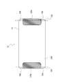
- FIG. 11 shows a rear view of the mobile terminal device 2 according to the first modification of the present embodiment.
- resin materials 120 are arranged at the four corners of the outer surface of the case body 11.
- the carbon composite material 110 extends to both ends in the longitudinal direction of the housing body 11. Further, the carbon composite material 110 extends to both ends in the short direction of the housing body 11.
- the carbon composite material 110 reaches the center region of both ends in the short direction of the housing body 11 and is sandwiched between the resin materials 120 arranged at the four corners. In addition, the carbon composite material 110 reaches the central region of both end portions in the longitudinal direction of the housing main body 11 and is sandwiched between the resin materials 120 arranged at the four corners.
- the carbon composite material 110 is separated from the first end 101 that is one end in the longitudinal direction of the housing main body 11 from the first housing 101. Extends to the second end 102 which is the other end in the longitudinal direction. Therefore, similarly to the portable terminal device 1 according to the above-described embodiment, warpage in the longitudinal direction of the housing 10 can be suppressed. Further, the carbon composite material 110 reaches both ends of the casing body 11 in the short direction. Therefore, it is possible to suppress warpage of the casing 10 in the short direction.
- the impact of the drop is received only at one point of the corner, so that the corner receives a strong impact. Since the resin material 120 is disposed at the four corners of the casing body 11 according to the first modification, even when the casing body 10 falls from the corner of the casing 10, the impact received by the mobile terminal device 2 is reduced. 120 can be absorbed.
- FIG. 1 The rear view of the portable terminal device 3 concerning the modification 2 of this Embodiment is shown in FIG.
- resin materials 120 are disposed at the four corners of the outer surface of the housing body 11.
- the resin material 120 is in contact with the end portion in the short direction of the housing body 11, and the second end that is the other end in the longitudinal direction of the housing body 11 from the first end 101 that is one end in the longitudinal direction. Extends to the end 102 of the.
- the carbon composite material 110 extends to both ends in the longitudinal direction of the housing body 11.
- the carbon composite material 110 on the outer surface of the housing main body 11 is sandwiched by the resin material 120 in the lateral direction of the housing main body 11 from the first end 101 to the second end 102.
- the carbon composite material 110 is separated from the first end 101 that is one end in the longitudinal direction of the housing main body 11 from the first housing 101. Extends to the second end 102 which is the other end in the longitudinal direction. Therefore, similarly to the portable terminal device 1 according to the above-described embodiment, warpage in the longitudinal direction of the housing 10 can be suppressed.
Landscapes
- Engineering & Computer Science (AREA)
- Computer Hardware Design (AREA)
- Theoretical Computer Science (AREA)
- General Engineering & Computer Science (AREA)
- Human Computer Interaction (AREA)
- Physics & Mathematics (AREA)
- General Physics & Mathematics (AREA)
- Signal Processing (AREA)
- Telephone Set Structure (AREA)
Applications Claiming Priority (2)
| Application Number | Priority Date | Filing Date | Title |
|---|---|---|---|
| JP2012128101 | 2012-06-05 | ||
| JP2012-128101 | 2012-06-05 |
Publications (1)
| Publication Number | Publication Date |
|---|---|
| WO2013183192A1 true WO2013183192A1 (fr) | 2013-12-12 |
Family
ID=49711603
Family Applications (1)
| Application Number | Title | Priority Date | Filing Date |
|---|---|---|---|
| PCT/JP2013/000051 Ceased WO2013183192A1 (fr) | 2012-06-05 | 2013-01-10 | Dispositif de terminal mobile |
Country Status (1)
| Country | Link |
|---|---|
| WO (1) | WO2013183192A1 (fr) |
Cited By (2)
| Publication number | Priority date | Publication date | Assignee | Title |
|---|---|---|---|---|
| JP2020017649A (ja) * | 2018-07-26 | 2020-01-30 | 矢崎総業株式会社 | カバー、該カバーを備えた回路基板ユニット、及び、前記カバーの製造方法 |
| JP2020072112A (ja) * | 2018-10-29 | 2020-05-07 | 株式会社デンソー | 電子装置 |
Citations (3)
| Publication number | Priority date | Publication date | Assignee | Title |
|---|---|---|---|---|
| JP2002314262A (ja) * | 2001-04-17 | 2002-10-25 | Toray Ind Inc | 電子機器筐体 |
| JP2008288801A (ja) * | 2007-05-16 | 2008-11-27 | Sony Corp | 電子機器 |
| JP2009169506A (ja) * | 2008-01-11 | 2009-07-30 | Lenovo Singapore Pte Ltd | 電子機器の筐体構造および電子機器 |
-
2013
- 2013-01-10 WO PCT/JP2013/000051 patent/WO2013183192A1/fr not_active Ceased
Patent Citations (3)
| Publication number | Priority date | Publication date | Assignee | Title |
|---|---|---|---|---|
| JP2002314262A (ja) * | 2001-04-17 | 2002-10-25 | Toray Ind Inc | 電子機器筐体 |
| JP2008288801A (ja) * | 2007-05-16 | 2008-11-27 | Sony Corp | 電子機器 |
| JP2009169506A (ja) * | 2008-01-11 | 2009-07-30 | Lenovo Singapore Pte Ltd | 電子機器の筐体構造および電子機器 |
Cited By (4)
| Publication number | Priority date | Publication date | Assignee | Title |
|---|---|---|---|---|
| JP2020017649A (ja) * | 2018-07-26 | 2020-01-30 | 矢崎総業株式会社 | カバー、該カバーを備えた回路基板ユニット、及び、前記カバーの製造方法 |
| JP7154857B2 (ja) | 2018-07-26 | 2022-10-18 | 矢崎総業株式会社 | カバーの製造方法 |
| JP2020072112A (ja) * | 2018-10-29 | 2020-05-07 | 株式会社デンソー | 電子装置 |
| JP7155875B2 (ja) | 2018-10-29 | 2022-10-19 | 株式会社デンソー | 電子装置 |
Similar Documents
| Publication | Publication Date | Title |
|---|---|---|
| JPWO2013136398A1 (ja) | 携帯端末装置 | |
| WO2013108311A1 (fr) | Dispositif de terminal mobile | |
| US12035497B2 (en) | Display device | |
| WO2013108312A1 (fr) | Dispositif de terminal mobile | |
| US20130265504A1 (en) | Television and electronic apparatus | |
| ES2787880T3 (es) | Estructura de bastidor para evitar deformaciones y dispositivo electrónico que incluye la misma | |
| JP5417478B2 (ja) | 電子機器 | |
| WO2020228793A1 (fr) | Ensemble antenne, ensemble cadre intermédiaire et terminal mobile | |
| CN108539369B (zh) | 天线组件、天线组件的制作方法及电子设备 | |
| WO2013136397A1 (fr) | Dispositif de terminal portable | |
| WO2013183192A1 (fr) | Dispositif de terminal mobile | |
| CN105467648A (zh) | 背板组件和具有该背板组件的显示装置 | |
| CN108539370B (zh) | 壳体组件、天线组件及电子设备 | |
| CN102998819B (zh) | 显示装置 | |
| JP2014045292A (ja) | 携帯端末装置 | |
| CN108232406B (zh) | 天线组件及电子设备 | |
| JP6765196B2 (ja) | 金属基板および電子機器 | |
| WO2013183193A1 (fr) | Dispositif de terminal mobile | |
| JP2010102249A (ja) | 携帯機器およびその製造方法 | |
| JP2014045296A (ja) | 携帯端末装置 | |
| JP5941360B2 (ja) | 携帯端末 | |
| CN108271326B (zh) | 中框及电子设备 | |
| CN108039573B (zh) | 天线组件以及电子设备 | |
| JP2014033393A (ja) | 携帯端末 | |
| KR101646826B1 (ko) | 커브드 pcm |
Legal Events
| Date | Code | Title | Description |
|---|---|---|---|
| 121 | Ep: the epo has been informed by wipo that ep was designated in this application |
Ref document number: 13800664 Country of ref document: EP Kind code of ref document: A1 |
|
| NENP | Non-entry into the national phase |
Ref country code: DE |
|
| 122 | Ep: pct application non-entry in european phase |
Ref document number: 13800664 Country of ref document: EP Kind code of ref document: A1 |
|
| NENP | Non-entry into the national phase |
Ref country code: JP |