WO2013183258A1 - Machine à laver - Google Patents
Machine à laver Download PDFInfo
- Publication number
- WO2013183258A1 WO2013183258A1 PCT/JP2013/003408 JP2013003408W WO2013183258A1 WO 2013183258 A1 WO2013183258 A1 WO 2013183258A1 JP 2013003408 W JP2013003408 W JP 2013003408W WO 2013183258 A1 WO2013183258 A1 WO 2013183258A1
- Authority
- WO
- WIPO (PCT)
- Prior art keywords
- water
- steam
- storage tank
- heater
- washing
- Prior art date
- Legal status (The legal status is an assumption and is not a legal conclusion. Google has not performed a legal analysis and makes no representation as to the accuracy of the status listed.)
- Ceased
Links
Images






Classifications
-
- D—TEXTILES; PAPER
- D06—TREATMENT OF TEXTILES OR THE LIKE; LAUNDERING; FLEXIBLE MATERIALS NOT OTHERWISE PROVIDED FOR
- D06F—LAUNDERING, DRYING, IRONING, PRESSING OR FOLDING TEXTILE ARTICLES
- D06F39/00—Details of washing machines not specific to a single type of machines covered by groups D06F9/00 - D06F27/00
- D06F39/04—Heating arrangements
-
- D—TEXTILES; PAPER
- D06—TREATMENT OF TEXTILES OR THE LIKE; LAUNDERING; FLEXIBLE MATERIALS NOT OTHERWISE PROVIDED FOR
- D06F—LAUNDERING, DRYING, IRONING, PRESSING OR FOLDING TEXTILE ARTICLES
- D06F33/00—Control of operations performed in washing machines or washer-dryers
- D06F33/30—Control of washing machines characterised by the purpose or target of the control
- D06F33/32—Control of operational steps, e.g. optimisation or improvement of operational steps depending on the condition of the laundry
-
- D—TEXTILES; PAPER
- D06—TREATMENT OF TEXTILES OR THE LIKE; LAUNDERING; FLEXIBLE MATERIALS NOT OTHERWISE PROVIDED FOR
- D06F—LAUNDERING, DRYING, IRONING, PRESSING OR FOLDING TEXTILE ARTICLES
- D06F39/00—Details of washing machines not specific to a single type of machines covered by groups D06F9/00 - D06F27/00
- D06F39/40—Steam generating arrangements
-
- D—TEXTILES; PAPER
- D06—TREATMENT OF TEXTILES OR THE LIKE; LAUNDERING; FLEXIBLE MATERIALS NOT OTHERWISE PROVIDED FOR
- D06F—LAUNDERING, DRYING, IRONING, PRESSING OR FOLDING TEXTILE ARTICLES
- D06F2103/00—Parameters monitored or detected for the control of domestic laundry washing machines, washer-dryers or laundry dryers
- D06F2103/16—Washing liquid temperature
-
- D—TEXTILES; PAPER
- D06—TREATMENT OF TEXTILES OR THE LIKE; LAUNDERING; FLEXIBLE MATERIALS NOT OTHERWISE PROVIDED FOR
- D06F—LAUNDERING, DRYING, IRONING, PRESSING OR FOLDING TEXTILE ARTICLES
- D06F2103/00—Parameters monitored or detected for the control of domestic laundry washing machines, washer-dryers or laundry dryers
- D06F2103/18—Washing liquid level
-
- D—TEXTILES; PAPER
- D06—TREATMENT OF TEXTILES OR THE LIKE; LAUNDERING; FLEXIBLE MATERIALS NOT OTHERWISE PROVIDED FOR
- D06F—LAUNDERING, DRYING, IRONING, PRESSING OR FOLDING TEXTILE ARTICLES
- D06F2105/00—Systems or parameters controlled or affected by the control systems of washing machines, washer-dryers or laundry dryers
- D06F2105/02—Water supply
-
- D—TEXTILES; PAPER
- D06—TREATMENT OF TEXTILES OR THE LIKE; LAUNDERING; FLEXIBLE MATERIALS NOT OTHERWISE PROVIDED FOR
- D06F—LAUNDERING, DRYING, IRONING, PRESSING OR FOLDING TEXTILE ARTICLES
- D06F2105/00—Systems or parameters controlled or affected by the control systems of washing machines, washer-dryers or laundry dryers
- D06F2105/10—Temperature of washing liquids; Heating means therefor
-
- D—TEXTILES; PAPER
- D06—TREATMENT OF TEXTILES OR THE LIKE; LAUNDERING; FLEXIBLE MATERIALS NOT OTHERWISE PROVIDED FOR
- D06F—LAUNDERING, DRYING, IRONING, PRESSING OR FOLDING TEXTILE ARTICLES
- D06F39/00—Details of washing machines not specific to a single type of machines covered by groups D06F9/00 - D06F27/00
- D06F39/08—Liquid supply or discharge arrangements
- D06F39/088—Liquid supply arrangements
Definitions
- the present invention relates to a washing machine for washing clothes.
- Patent Documents 1 and 2 A washing machine that supplies steam to a storage tank that stores clothing and performs various treatments on the clothing has been developed (see Patent Documents 1 and 2).
- the washing machines disclosed in Patent Documents 1 and 2 supply steam to the storage tank in synchronization with the start of supply of washing water for washing clothes. Since the washing water is warmed by the steam, the washing machine can exhibit a high washing ability.
- An object of the present invention is to provide an efficient washing machine that can exhibit high cleaning ability using steam.
- a washing machine includes a storage tank that stores washing water for washing clothes, a first heater that heats the washing water, a steam supply mechanism that supplies steam to the storage tank, A control unit for controlling the steam supply mechanism and the first heater. The controller operates the steam supply mechanism after stopping the first heater.
- the washing machine according to the present invention can exhibit high cleaning ability using steam.
- FIG. 2 is a schematic perspective view of the washing machine shown in FIG. 1. It is a schematic perspective view of the steam supply mechanism accommodated in the housing of the washing machine shown in FIG. It is a schematic perspective view of the steam generation part of the steam supply mechanism shown by FIG. It is a schematic perspective view of the steam generation part of the steam supply mechanism shown by FIG. It is a schematic perspective view of the attachment part for connecting the cover part and housing
- FIG. 9 is a schematic exploded perspective view of the steam generator shown in FIGS. 8A and 8B.
- FIG. 10 is a schematic plan view of the main piece shown in FIG. 9. It is the schematic of the water supply mechanism of the steam supply mechanism shown by FIG.
- FIG. 2 is a schematic block diagram representing various elements of a washing machine used in a washing process. It is a schematic flowchart showing the control for adjusting the temperature of washing water. It is a graph which represents roughly the change of the temperature of the water supplied to the water tank of the washing machine shown by FIG. It is a schematic timing chart showing the timing of the steam supply during a dehydration process. It is a schematic timing chart showing the timing of the steam supply during a dehydration process.
- FIG. 8B It is a schematic timing chart showing the timing of the steam supply during a dehydration process. It is a block diagram showing roughly control to a door based on a temperature of a steam generator shown in Drawing 8B. It is a general
- washing machine will be described with reference to the drawings. It should be noted that the terms such as “up”, “down”, “left”, and “right” used in the following description are merely for the purpose of clarifying the explanation, and the principle of the washing machine is used. It is not limited at all. The principle of the washing machine can be applied not only to a washing function but also to a device having a drying function for drying clothes (washing and drying machine).
- FIG. 1 is a schematic longitudinal sectional view of the washing machine 100 of the first embodiment. The washing machine 100 will be described with reference to FIG.
- the washing machine 100 includes a casing 110 and a storage tank 200 that stores clothes in the casing 110.
- the storage tank 200 includes a rotary drum 210 having a substantially cylindrical peripheral wall 211 that surrounds the rotation axis RX, and a water tank 220 that stores the rotary drum 210.
- the storage tank 200 is formed in a substantially cylindrical shape surrounding the rotation axis RX.
- the storage tank 200 stores clothes and washing water for washing clothes.
- the washing water is drained from the storage tank 200. Thereafter, the rotating drum 210 rotates at a high speed.
- the washing machine 100 includes a hot water heater 160 for heating the washing water.
- the hot water heater 160 is disposed below the water tank 220. Control using the hot water heater 160 will be described later.
- the hot water heater 160 is exemplified as the first heater.
- the housing 110 includes a front wall 111 in which an input port 119 for inputting clothes into the storage tank 200 is formed, and a rear wall 112 on the opposite side of the front wall 111.
- the housing 110 includes a housing top wall 113 that extends substantially horizontally between the front wall 111 and the rear wall 112, and a housing bottom wall 114 on the opposite side of the housing top wall 113.
- the rotating drum 210 and the water tank 220 are formed with openings 213 and 227 communicating with the charging port 119 formed in the front wall 111, respectively.
- the washing machine 100 further includes a door 120 attached to the front wall 111.
- the door body 120 rotates between a closed position that closes the input port 119 formed in the front wall 111 and an open position that opens the input port 119.
- the user can turn the door 120 to the open position and put the clothes into the storage tub 200 through the insertion port 119 of the front wall 111. Thereafter, the user can move the door 120 to the closed position and cause the washing machine 100 to wash clothes.
- the door 120 shown in FIG. 1 is in the closed position.
- the rotating drum 210 rotates around a rotation axis RX extending between the front wall 111 and the rear wall 112.
- the clothes put in the storage tank 200 move in the rotary drum 210 as the rotary drum 210 rotates, and are subjected to various processes such as washing, rinsing and / or dehydration.
- the rotary drum 210 includes a bottom wall 212 that faces the door 120 at the closed position.
- the water tank 220 includes a bottom 221 that surrounds a part of the bottom wall 212 and the peripheral wall 211 of the rotary drum 210, and a front part 222 that surrounds the other part of the peripheral wall 211 of the rotary drum 210 between the bottom 221 and the door body 120. .
- the storage tank 200 includes a rotating shaft 230 attached to the bottom wall 212 of the rotating drum 210.
- the rotation shaft 230 extends toward the rear wall 112 along the rotation axis RX.
- the rotating shaft 230 passes through the bottom 221 of the water tank 220 and appears between the water tank 220 and the rear wall 112.
- the washing machine 100 includes a motor 231 installed below the water tank 220, a pulley 232 attached to the rotating shaft 230 exposed outside the water tank 220, and a belt 233 for transmitting the power of the motor 231 to the pulley 232.
- a motor 231 installed below the water tank 220
- a pulley 232 attached to the rotating shaft 230 exposed outside the water tank 220
- a belt 233 for transmitting the power of the motor 231 to the pulley 232.
- the motor 231 operates, the power of the motor 231 is transmitted to the belt 233, the pulley 232, and the rotating shaft 230.
- the rotating drum 210 rotates in the water tank 220.
- the washing machine 100 further includes a packing structure 130 disposed between the front portion 222 of the water tank 220 and the door body 120.
- the door 120 rotated to the closed position compresses the packing structure 130.
- the packing structure 130 forms a watertight seal structure between the door body 120 and the front portion 222.
- Washing machine 100 further includes a water supply port 140 connected to a faucet (not shown), and a distribution unit 141 for distributing water introduced through water supply port 140.
- the water supply port 140 appears on the housing top wall 113 lying on the storage tank 200.
- the distribution unit 141 is disposed between the housing top wall 113 and the storage tank 200.
- the washing machine 100 further includes a detergent container (not shown) in which detergent is accommodated, and a steam supply mechanism 300 (described later) that injects steam into the container 200.
- the distribution unit 141 includes a plurality of water supply valves for selectively supplying water to the storage tank 200, the detergent storage unit, and the steam supply mechanism 300.
- route to the storage tank 200 and a detergent storage part is not shown.
- a technique used in a known washing machine is suitably applied to water supply to the storage tank 200 and the detergent storage unit.
- FIG. 2 is a schematic perspective view of the washing machine 100.
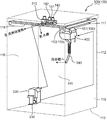
- FIG. 3 is a schematic perspective view of the steam supply mechanism 300 accommodated in the housing 110. 2 and 3, the housing 110 is represented by a dotted line. In FIG. 3, the storage tank 200 is not shown. The arrows in FIG. 3 schematically represent the water supply path.
- the steam supply mechanism 300 is described with reference to FIGS. 1 to 3.
- the distribution unit 141 includes a first water supply valve 310 used in the steam supply mechanism 300, a second water supply valve 142 that opens and closes a water supply path to the detergent storage unit in which the detergent is stored, and a water tank 220. And a third water supply valve 143 that opens and closes the water supply path to.
- the water supplied to the detergent container by the opening operation of the second water supply valve 142 is supplied to the container 200 as washing water (water in which the detergent is dissolved).
- the water directly supplied to the water tank 220 by the opening operation of the third water supply valve 143 adjusts the concentration of the detergent in the washing water in the storage tank 200, adjusts the water level in the storage tank 200, and adjusts the turbidity of the washing water. May be used for
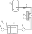
- the steam supply mechanism 300 includes a water storage tank 320 disposed below the storage tank 200 in addition to the first water supply valve 310 described above.
- the first water supply valve 310 is used to control water supply to the water storage tank 320.
- water is supplied from the water supply port 140 to the water storage tank 320.
- the first water supply valve 310 is closed, water supply to the water storage tank 320 is stopped.
- the steam supply mechanism 300 further includes a pump 330 attached to the water storage tank 320 and a steam generator 400 that receives water discharged from the pump 330.
- the pump 330 performs an intermittent or continuous water supply operation on the steam generation unit 400. During the intermittent water supply operation, the pump 330 supplies an appropriate amount of water adjusted so that instantaneous steam generation occurs to the steam generation unit 400. If the pump 330 continuously supplies water to the steam generation unit 400, impurities (scale) contained in the water used for generating steam are washed away from the steam generation unit 400.
- the steam generator 400 is heated to a high temperature in order to generate steam to be injected into the storage tank 200. Since the housing 110 houses the housing tank 200 including the rotating drum 210 that rotates and the steam generator 400 heated to a high temperature, the housing tank 200 and the steam generator 400 are appropriately isolated from the user. The Therefore, the user can operate the washing machine 100 safely.
- the steam supply mechanism 300 further includes a steam conduction pipe 340 extending downward from the steam generation unit 400.
- the front portion 222 of the water tank 220 includes a peripheral wall portion 223 that surrounds the peripheral wall 211 of the rotating drum 210 and an annular portion 224 that cooperates with the packing structure 130 to form a watertight seal structure.
- the steam conduction pipe 340 is connected to the peripheral wall part 223.
- the steam generated by the steam generation unit 400 is supplied to the storage tank 200 through the steam conduction pipe 340.
- tube 340 is made into a bellows shape so that the vibration at the time of rotating the storage tank 200 may not be transmitted to the steam generation part 400.
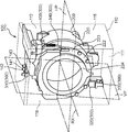
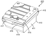
- FIGS. 4A and 4B are schematic perspective views of the steam generating unit 400.
- FIG. The steam generation unit 400 is described with reference to FIGS. 2 to 4B.
- the steam generating unit 400 includes a substantially rectangular box-shaped case 410 and a steam generator 420 surrounded by the case 410.
- the case 410 includes a container part 411 for housing the steam generator 420 and a lid part 412 that closes the container part 411.
- the steam generator 420 is connected to the pump 330 using a connection pipe 421 and a tube (not shown). Further, the steam generator 420 is connected to the steam conduction pipe 340 using the exhaust pipe 422.
- the container part 411 includes a bottom wall part 414 in which an opening 413 is formed. The connection pipe 421 and the exhaust pipe 422 protrude downward through the opening 413.
- the steam generator 420 Since the pump 330 forcibly supplies water from the water storage tank 320 to the steam generator 420 in the steam generation unit 400, the steam generator 420 is disposed above the water storage tank 320. If water is supplied from the water storage tank 320 to the steam generator 420 without the pump 330, the water in the water storage tank 320 needs to be sent to the steam generator 420 by the action of gravity. In this case, the steam generator 420 needs to be disposed below the water storage tank 320.
- water supply from the water storage tank 320 to the steam generator 420 is performed using the pump 330. Since water is forcibly supplied from the water storage tank 320 to the steam generator 420 by the pressure of the pump 330, there is little restriction on the vertical relationship regarding the layout design of the steam generator 420 and the water storage tank 320. Since the degree of freedom in the layout design of the water storage tank 320 and the steam generator 420 is increased, the space in the housing 110 is effectively used.
- the steam generator 420 is disposed above the water storage tank 320, but the pump 330 can appropriately supply water from the water storage tank 320 to the steam generator 420.
- the housing 110 includes a right wall 115 erected between the front wall 111 and the rear wall 112, and a left wall 116 opposite to the right wall 115.
- the rotation axis RX extends along the right wall 115 and the left wall 116 (that is, the rotation axis RX extends substantially parallel to the right wall 115 and the left wall 116).
- the vertical plane VP passing through the rotation axis RX is represented by a one-dot chain line.
- the water storage tank 320 is disposed in a lower left space of the housing 110 (a space between the vertical plane VP and the left wall 116).
- the steam generator 420 is disposed in the upper right space of the housing 110 (the space between the vertical plane VP and the right wall 115).
- the steam generator 420 and the water storage tank 320 are disposed at substantially symmetrical positions with respect to the central axis (rotation axis RX) of the storage tank 200.
- the water tank 320 is disposed near the rear wall 112, while the steam generator 420 is disposed near the front wall 111 rather than the rear wall 112.
- a detergent container that accommodates detergent is disposed on one of the left and right sides in front of the upper part of the housing.
- the space outside the substantially cylindrical storage tank 200 excluding the position occupied by the detergent storage section is effectively utilized for arranging the water storage tank 320 and the steam generator 420, respectively.
- the water storage tank 320 is disposed on the lower left side of the housing 110 as shown in FIG. 2.
- the steam generator 420 is disposed in front of the upper right side of the housing 110, the internal space between the inner surface of the substantially rectangular box-shaped housing 110 and the outer surface of the substantially cylindrical storage tank 200 is:
- the storage tank 320 and the steam generator 420 are effectively used for the arrangement.
- the water tank 320 and the steam generator 420 may be designed to be as large as possible within the allowed space.
- the water storage tank 320 is disposed at a position substantially symmetrical to the detergent container with respect to the central axis (rotation axis RX) of the container 200, and the steam generator 420 is The water tank 320 may be disposed at a position substantially symmetrical with respect to the horizontal plane HP including the rotation axis RX of the storage tank 200. Similar to the layout design described above, the space inside the housing 110 is effectively utilized.
- the water storage tank 320 may be disposed below the detergent container.
- the steam generator 420 may be disposed above the water storage tank 320.
- the steam generator 420 may be disposed at a position substantially symmetrical to the water storage tank 320 with respect to a vertical plane including the rotation axis RX of the storage tank 200.
- the water storage tank 320 and the steam generator 420 may be disposed at substantially symmetrical positions with respect to the rotation axis RX of the storage tank 200 or the horizontal plane HP including the rotation axis RX. If the water storage tank 320 and the steam generator 420 are disposed at a position that is substantially symmetrical with respect to a vertical plane that passes through the approximate center in the front-rear direction of the casing 110, the space between the inner surface of the casing 110 and the outer surface of the storage tank 200 is reduced. The internal space is effectively utilized for arranging the water storage tank 320 and the steam generator 420.
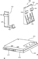
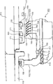
- FIG. 5 is a schematic perspective view of the attachment portion 150 attached to the lid portion 412.
- the attachment part 150 will be described with reference to FIGS. 3 and 5.
- the lid 412 includes a substantially rectangular upper wall 415, a lid peripheral wall 416 that projects downward from the edge of the upper wall 415, and a projecting piece 417 that projects forward from the lid peripheral wall 416.
- the washing machine 100 includes an attachment portion 150 that is attached to the lid portion 412.
- the mounting portion 150 includes a first mounting piece 151 fixed to the upper wall 415 and a second mounting piece 152 fixed to the protruding piece 417.
- the first attachment piece 151 and the second attachment piece 152 protrude upward from the lid portion 412.
- the first attachment piece 151 includes a first connection plate 153 connected to the upper wall 415, a first upright plate 154 protruding upward from the first connection plate 153, and a pair protruding rightward from the first upright plate 154.
- the second mounting piece 152 includes a second connecting plate 156 connected to the protruding piece 417, a second upright plate 157 protruding upward from the second connecting plate 156, and a second protruding forward from the second upright plate 157.
- Engaging piece 158 is a first connection plate 153 connected to the upper wall 415, a first upright plate 154 protruding upward from the first connection plate 153, and a pair protruding rightward from the first upright plate 154.
- FIG. 6 is a schematic perspective view of the steam generation unit 400 fixed to the housing top wall 113 using the attachment unit 150. The attachment of the steam generation unit 400 to the housing top wall 113 will be described with reference to FIGS. 3 and 6.
- the housing 110 includes a first reinforcement frame 117 disposed along the upper edge of the right wall 115 and a second reinforcement frame 118 disposed along the upper edge of the front wall 111. And further comprising.
- a plurality of openings 171 are formed in the first reinforcing frame 117.
- the first engagement piece 155 of the first attachment piece 151 is inserted into the opening 171.
- the first attachment piece 151 is engaged with the first reinforcement frame 117.
- the first mounting piece 151 includes a plurality of first fins 159 formed at corners between the first connection plate 153 and the first upright plate 154. Since most of the heat of the steam generating unit 400 is radiated through the first fins 159, the amount of heat transmitted to the first reinforcing frame 117 and the case ceiling wall 113 is reduced.
- An opening is also formed in the second reinforcing frame 118.
- the second engagement piece 158 of the second attachment piece 152 is inserted into the opening of the second reinforcement frame 118.
- the second attachment piece 152 is engaged with the second reinforcing frame 118.
- the steam generating unit 400 is fixed to the housing top wall 113 by the first mounting piece 151 and the second mounting piece 152.
- the steam generator 400 is separated from the housing top wall 113 by a first upright plate 154 and a second upright plate 157 that are erected upward.
- an air layer exists between the lid portion 412 and the housing top wall 113. Therefore, the heat transfer from the steam generation part 400 to the housing top wall 113 is alleviated.
- the protruding piece 417 to which the second connection plate 156 of the second mounting piece 152 is connected includes a plurality of second fins 418 protruding downward. Since most of the heat of the steam generating unit 400 is radiated through the second fins 418, the amount of heat transmitted to the second connection plate 156 is reduced.
- the second upright plate 157 is narrower than the second connection plate 156. Therefore, the amount of heat conducted from the second connection plate 156 to the second upright plate 157 is reduced. As a result, the amount of heat transferred to the second reinforcing frame 118 and the case ceiling wall 113 via the second upright plate 157 is reduced.
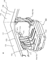
- FIG. 7 is a schematic perspective view of the steam generating unit 400 connected to the first reinforcing frame 117 and the second reinforcing frame 118. The attachment of the steam generation unit 400 will be described with reference to FIG.
- the outer contour of the housing 110 is represented by a one-dot chain line.
- the first reinforcing frame 117 includes an outer edge 172 near the right wall 115 extending downward from the housing top wall 113, and an inner edge 173 farther from the right wall 115 than the outer edge 172.
- the first reinforcing frame 117 further includes a rib 174 extending downward from the inner edge 173.
- the opening 171 described above is formed in the rib 174.
- the first engagement piece 155 of the first attachment piece 151 is inserted into the opening 171 and protrudes toward the right wall 115.
- the first attachment piece 151 is connected along the right edge of the lid portion 412. Therefore, the steam generation unit 400 is appropriately separated from the right wall 115 of the housing 110 by the first attachment piece 151. As a result, heat transfer from the steam generator 400 to the right wall 115 is alleviated.
- the front wall 111 adjacent to the right wall 115 extends downward from the housing top wall 113.
- the second mounting piece 152 suspended from the second reinforcing frame 118 is curved in the direction opposite to the front wall 111 and is connected to the steam generating unit 400. Therefore, the steam generator 400 is appropriately separated from the front wall 111 of the housing 110 by the second mounting piece 152. Thus, the steam generation unit 400 is held by the mounting unit 150 away from the housing 110.
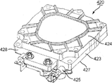
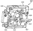
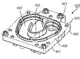
- ⁇ Steam generator> 8A and 8B are schematic perspective views of the steam generator 420.
- the steam generator 420 is described with reference to FIGS. 8A and 8B.
- the steam generator 420 includes a substantially rectangular main piece 423, a lid piece 424 disposed on the main piece 423, and a linear heater 425 disposed on the main piece 423.
- the main piece 423 and the lid piece 424 are made of aluminum. Therefore, the main piece 423 and the lid piece 424 are appropriately heated by the heater 425.
- the steam generator 420 further includes a thermistor 426.
- the thermistor 426 is also attached to the main piece 423.
- the heater 425 is controlled by temperature information obtained by the thermistor 426 using the thermistor 426. Therefore, the temperature of the main piece 423 and the lid piece 424 is kept substantially constant. The same effect can be obtained by using a thermostat that controls on / off of the heater 425 at a predetermined temperature instead of the thermistor 426.
- FIG. 9 is a schematic perspective view of the main piece 423.
- the main piece 423 will be described with reference to FIGS. 8B and 9.
- the main piece 423 includes a main piece lower surface 427 to which the connection pipe 421, the exhaust pipe 422 and the thermistor 426 are attached, a peripheral surface 428 on which the heater 425 is disposed, and an upper surface 429 on the opposite side of the main piece lower surface 427. Including.
- the main piece 423 is erected from the upper surface 429 toward the lid piece 424, and has an outer chamber wall 431 that defines a substantially triangular chamber space 430, and a substantially J shape that defines a flow path for steam in the chamber space 430. And an inner chamber wall 432.
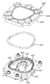
- FIG. 10 is a schematic exploded perspective view of the steam generator 420.
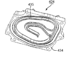
- FIG. 11 is a schematic perspective view of the lid piece 424.
- the steam generator 420 is described with reference to FIGS. 2, 3 and 8B to 11.
- the steam generator 420 includes a packing ring 433 attached to the main piece 423 so as to surround the outer chamber wall 431.
- the packing ring 433 is made of heat resistant rubber.
- the lid piece 424 includes a lower surface 434 facing the main piece 423, and an outer shield wall 435 having substantially the same shape as the outer chamber wall 431.
- the lid piece 424 is pressed against the main piece 423.
- the outer shield wall 435 compresses the packing ring 433 and keeps the chamber space 430 airtight.
- the main piece 423 is formed with an inlet 437 through which water supplied through the connection pipe 421 flows into the chamber space 430.
- An inflow port 437 formed substantially at the center of the chamber space 430 is surrounded by the inner chamber wall 432. If the pump 330 supplies a predetermined amount of water to the steam generator 420, the water is injected upward through the connection pipe 421 and the inlet 437. As a result, the water collides with the inner chamber wall 432, the upper surface 429 of the main piece 423 surrounded by the inner chamber wall 432 and / or the lower surface 434 of the lid piece 424 positioned above the inflow port 437.
- the steam generator 420 is heated by a heater 425 (eg, about 200 ° C.) and has high thermal energy.
- the pump 330 that performs intermittent water supply operation supplies an appropriate amount of water to the heat energy of the steam generator 420 (for example, about 2 cc / time).
- the chamber space 430 used for generating steam is exemplified as a chamber.
- the inner chamber wall 432 that the water supplied through the inlet 437 collides with, the upper surface 429 of the main piece 423 surrounded by the inner chamber wall 432 and / or the lower surface 434 of the lid piece 424 positioned above the inlet 437 has a wall surface As an example.
- the heater 425 is exemplified as the second heater.
- Impurities contained in water supplied to the steam generator 420 may adhere to or deposit on the wall surface forming the chamber space 430 during vaporization.
- the internal pressure of the chamber space 430 increases rapidly, so that the adhered or precipitated impurities are easily discharged from the chamber space 430 under the action of the pressure during vaporization.
- the steam generator 420 is disposed above the storage tank 200.
- impurities contained in the water supplied to the steam generator 420 cause the chamber space 430 such as the outer chamber wall 431, the inner chamber wall 432, the upper surface 429, and the lower surface 434 of the lid piece 424 of the main piece 423 during vaporization. It may adhere or deposit on the wall surface to be formed. If the impurities accumulate, the heat transfer efficiency between the wall surface and the supplied water is reduced. As a result, water becomes difficult to evaporate.
- the steam generator 420 is disposed above the storage tank 200, the adhered or deposited impurities are discharged or dropped below the steam generator 420 by the action of pressure during vaporization or gravity.
- impurities are easily discharged from the chamber space 430 to the storage tank 200.
- the accumulation of impurities deposited or deposited in the chamber of the steam generator 420 is appropriately removed. Therefore, the vaporization ability due to impurity deposition is unlikely to decrease.
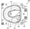
- FIG. 12 is a schematic plan view of the main piece 423.
- the main piece 423 will be described with reference to FIGS. 8B and 12.
- the heater 425 extends along a substantially U-shaped path in the main piece 423. As a result, the heater 425 surrounds the inflow port 437 to which the connection pipe 421 is attached. As a result, the inner chamber wall 432 and the region surrounded by the inner chamber wall 432 have the highest temperature in the chamber space 430. Therefore, the water emitted through the inlet 437 evaporates instantaneously.
- the main piece 423 has an exhaust port 438 formed at the end of the flow path.
- the vapor generated in the space surrounded by the inner chamber wall 432 moves toward the exhaust port 438 as the internal pressure of the chamber space 430 increases.
- An exhaust pipe 422 is attached to the exhaust port 438. The steam that has reached the exhaust port 438 is exhausted downward through the exhaust pipe 422.
- the heater 425 extends in a U shape along the outer path of the spiral flow path. Therefore, the steam generated in the space surrounded by the inner chamber wall 432 moves toward the exhaust pipe 422 while being heated. Therefore, high-temperature steam is exhausted.
- the steam generator 420 emits water to the heated wall surface and instantly evaporates it, less power is required to generate the same amount of steam compared to the prior art that generates steam with a heater immersed in water. That's it.
- FIG. 13 is a schematic diagram of the water supply mechanism 500. The water supply mechanism 500 is demonstrated using FIG.
- the water supply mechanism 500 that emits water to the chamber space 430 of the steam generator 420 includes the first water supply valve 310, the water storage tank 320, the pump 330, and the connection pipe 421.
- the water supply mechanism 500 further includes a water level sensor 321 for measuring the water level stored in the water storage tank 320.
- the first water supply valve 310 may supply water to the water storage tank 320 or stop water supply to the water storage tank 320 according to the water level detected by the water level sensor 321.
- the first water supply valve 310 may be controlled according to the operation time and / or operation pattern of the pump 330 (intermittent water supply operation and / or continuous water supply operation). For example, the amount of water supplied from the first water supply valve 310 may be adjusted so that the water storage tank 320 becomes empty when the operation of the pump 330 is completed. As a result, the water in the water storage tank 320 is hardly frozen.
- the pump 330 supplies the water stored in the water storage tank 320 to the chamber space 430 through the connection pipe 421.
- the intermittent water supply operation of the pump 330 is adjusted so that water emitted into the chamber space 430 is instantly evaporated.
- impurities contained in water may be deposited in the chamber space 430.
- the continuous water supply operation of the pump 330 is adjusted so that water flows into the chamber space 430 at a flow rate sufficient to sweep away accumulated impurities.
- the exhaust pipe 422 is connected to the steam conduction pipe 340.
- the steam generated in the chamber space 430 by the intermittent water supply operation of the pump 330 and the water flowing into the chamber space 430 by the continuous water supply operation of the pump 330 enter the storage tank 200 through the exhaust pipe 422 and the steam conduction pipe 340. Inflow.
- FIG. 14 is a schematic rear view of the front portion 222 of the storage tank 200. The supply of steam and water to the storage tank 200 will be described with reference to FIGS. 1, 13, and 14.
- the annular portion 224 of the front portion 222 includes an inner surface 225 that faces the rotating drum 210 and an outer surface 226 that faces the front wall 111 of the housing 110.
- FIG. 14 mainly shows the inner surface 225.
- the steam supply mechanism 300 includes a branch pipe 351 and a nozzle 352 attached to the inner surface 225.
- the steam supply mechanism 300 further includes a steam tube 353 that connects the branch pipe 351 and the nozzle 352.
- the steam conduction pipe 340 is connected to the branch pipe 351 through the peripheral wall portion 223.
- the steam generated in the chamber space 430 flows into the steam conduction pipe 340 through the exhaust pipe 422 as the pressure in the chamber space 430 increases. Thereafter, the steam reaches the branch pipe 351 from the steam conduction pipe 340.
- the nozzle 352 is disposed above the branch pipe 351. Since the steam reaching the branch pipe 351 is high temperature, it is guided to the steam tube 353 and reaches the nozzle 352. Eventually, the steam is jetted downward from the nozzle 352. As a result, the steam is sprayed directly on the clothes stored in the storage tank 200 through the opening 213 of the rotary drum 210.
- the exhaust pipe 422, the steam conduction pipe 340, the branch pipe 351, and the steam tube 353 guide the steam generated in the chamber space 430 to the nozzle 352.
- the pump 330 that performs intermittent water supply operation emits an appropriate amount of water to the high-temperature chamber space 430, so that the water evaporates instantaneously.
- the internal pressure of the chamber space 430 increases rapidly. Therefore, the steam is injected from the nozzle 352 at a high pressure, and traverses the internal space of the storage tank 200 up and down. Clothing tends to gather near the lower end of the rotating drum 210 due to gravity. Since the vapor
- the branch pipe 351 includes a parent pipe 354 connected to the steam conducting pipe 340, an upper pipe 355 bent upward from the parent pipe 354, and a lower pipe 356 bent downward from the parent pipe 354. Steam or water flows into the parent pipe 354 through the steam conducting pipe 340.
- the upper tube 355 is connected to the steam tube 353, and defines an upward path for the steam toward the nozzle 352.
- the lower tube 356 defines a downward path. While the pump 330 performs a continuous water supply operation, the water that flows into the branch pipe 351 through the steam conducting pipe 340 flows down through the lower pipe 356 by gravity.
- FIG. 14 shows the included angle ⁇ 1 between the parent tube 354 and the upper child tube 355.
- FIG. 14 also shows the included angle ⁇ ⁇ b> 2 between the parent tube 354 and the lower child tube 356.
- the included angle ⁇ 1 is an obtuse angle
- the included angle ⁇ 2 is an acute angle. Since the included angle ⁇ 2 is an acute angle, the flow loss from the parent tube 354 to the lower tube 356 is relatively large. Therefore, the steam that has flowed into the parent pipe 354 hardly flows to the lower child pipe 356 and flows mainly to the upper child pipe 355.
- the upper tube 355 defines an upward flow path, the water flowing into the parent tube 354 hardly flows to the upper tube 355 and mainly flows to the lower tube 356 due to the action of gravity. Therefore, the flow path of steam and the flow path of water are appropriately separated.
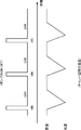
- FIG. 15 is a graph schematically showing the relationship between the intermittent operation of the pump 330 and the temperature in the chamber space 430. The intermittent operation of the pump 330 will be described with reference to FIGS. 10, 13, and 15.
- the period during which the pump 330 is operating (ON period) is set shorter than the period during which the pump 330 is stopped (OFF period). As a result, an appropriate amount of water is emitted into the chamber space 430.
- the ON period a predetermined amount of water is supplied to the chamber space 430.
- water evaporates and becomes steam.
- the temperature of the chamber space 430 temporarily decreases due to the heat of vaporization caused by the phase change from water to steam.
- the heater 425 can sufficiently raise the temperature of the chamber space 430 during the OFF period. Therefore, high-pressure steam continues to be supplied to the storage tank 200 while the pump 330 is intermittently operated.
- the chamber space 430 is sufficiently heated during the OFF period, and in the ON period, an appropriate amount of water that instantaneously evaporates is supplied to the thermal energy of the steam generator 420 including the chamber space 430 ( For example, about 2 cc / time), the high-pressure steam is continuously supplied to the storage tank 200.
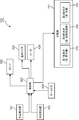
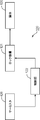
- FIG. 16 is a schematic block diagram showing various elements of the washing machine 100 used in the washing process. The operation of the washing machine 100 in the washing process will be described with reference to FIGS.
- the washing machine 100 includes a control unit 122, a water temperature detection unit 161, and a water level detection unit 162 in addition to the distribution unit 141, the hot water heater 160, and the heater 425.
- the water temperature detector 161 detects the temperature of the washing water stored in the storage tub 200.
- An example of the water temperature detector 161 is a temperature sensor (not shown) attached to the water tank 220.
- the water level detection unit 162 detects the water level of the washing water in the storage tub 200.
- the water level detection unit 162 includes a water level sensor (not shown) attached to the water tank 220, a flow meter and a second water supply valve attached to a path from the second water supply valve 142 and / or the third water supply valve 143 to the water tank 220. 142 and / or a timer that counts from the opening time of the third water supply valve 143 may be used.
- the water temperature detection part 161 is illustrated as a detection element.
- the control unit 122 controls the distribution unit 141, opens the second water supply valve 142 and the third water supply valve 143, and supplies wash water to the storage tank 200. During this time, the controller 122 may heat the steam generator 420 under feedback control between the thermistor 426 and the heater 425.
- the water level detection unit 162 outputs a detection signal including information on the water level of the washing water in the storage tub 200 to the control unit 122. Based on the detection signal from the water level detection unit 162, the control unit 122 determines whether the hot water heater 160 is immersed in the wash water. If the hot water heater 160 is immersed in the washing water, the control unit 122 operates the hot water heater 160.
- the water temperature detection unit 161 outputs a detection signal including information on the temperature of the washing water in the storage tub 200 to the control unit 122. Based on the detection signal from the water temperature detection unit 161, the control unit 122 determines whether the wash water has reached a first threshold temperature determined for the temperature of the wash water. If the washing water has reached a predetermined temperature, the hot water heater 160 is stopped. Thereafter, the control unit 122 operates the pump 330 (steam supply mechanism 300: water supply mechanism 500). While the pump 330 is operating, the control unit 122 supplies water to the water storage tank 320 as necessary under feedback control of the water level sensor 321 and the first water supply valve 310.
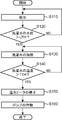
- FIG. 17 is a schematic flowchart showing the control for adjusting the temperature of the washing water. The control for adjusting the temperature of the washing water will be described with reference to FIGS. 1 and 15 to 17.
- step S110 In step S ⁇ b> 110, the control unit 122 opens the second water supply valve 142 and / or the third water supply valve 143 to supply water to the storage tank 200. Thereafter, step S120 is executed.
- Step S120 The control unit 122 stores in advance information related to the threshold value “LTH” determined for the water level of the washing water in the storage tub 200.
- the control unit 122 uses the detection signal output from the water level detection unit 162 to compare the washing water level in the storage tub 200 with the threshold “LTH”. If the water level of the washing water exceeds the threshold “LTH”, step S130 is executed. In other cases, step S110 is executed. If the water level of the washing water exceeds the threshold value “LTH”, the threshold value “LTH” is appropriately determined so that the warm water heater 160 is immersed in the washing water.
- the water level represented by the threshold “LTH” is exemplified as the predetermined water level.
- Step S130 the control unit 122 operates the hot water heater 160. As a result, the wash water is heated rapidly. When heating of the washing water is started, step S140 is executed.
- Step S140 The control unit 122 stores in advance information related to the first threshold temperature “TTH” determined for the temperature of the washing water in the storage tub 200.
- step S140 the control unit 122 compares the water temperature of the washing water in the storage tub 200 with the first threshold temperature “TTH” using the detection signal output from the water temperature detection unit 161. If the water temperature of the washing water exceeds the first threshold temperature “TTH”, step S150 is executed. In other cases, step S130 is executed.
- the water temperature represented by the first threshold temperature “TTH” is exemplified as the predetermined temperature.
- Step S150 the control unit 122 stops the hot water heater 160. Thereafter, step S160 is executed.
- Step S160 the control unit 122 operates the pump 330.
- the operation of the pump 330 in step S160 is intermittent as described with reference to FIG.
- the pump 330 may continue to operate intermittently until the washing process is completed.
- the operation of the pump 330 in step S160 may be controlled according to the temperature of the washing water. For example, when the water temperature detection unit 161 detects a temperature lower than the second threshold temperature set for the washing water temperature, the control unit 121 may cause the pump 330 to start an intermittent operation. Thereafter, if the pump 330 performs an intermittent operation for a predetermined period under the control of the control unit 121, the washing water is appropriately heated. If the control unit 121 stops the pump 330 after the predetermined period has elapsed, power consumption by the pump 330 is suppressed.
- FIG. 18 is a graph schematically showing a change in the temperature of the water supplied to the water tank 220 in the washing step. The effect of the steam used in the washing process will be described with reference to FIGS. 1, 10, 13 and 18.
- the dotted line after stopping the heating represents a change in the temperature of water contained in the clothing when the heating by the hot water heater 160 is stopped and no steam is supplied.
- the solid line after stopping the heating represents a change in the temperature of the water contained in the clothing when the heating by the hot water heater 160 is stopped and the steam is supplied to the storage tank 200.
- the steam supplied to the storage tank 200 has a high temperature and is directly supplied to the clothing, so that the temperature drop of the water contained in the clothing in the water tank 220 is alleviated.
- the heater 425 used in the steam generator 420 consumes less power than the hot water heater 160 attached to the water tank 220. Compared with the heat insulation of the water in the water tank 220 using the hot water heater 160, the heat insulation by the steam supply can achieve a small amount of power consumption. Therefore, the pump 330 preferably performs an intermittent water supply operation after the hot water heater 160 is stopped.
- the rotating drum 210 is rotated at a high speed. As shown in FIG. 1, a large number of small holes 219 are formed in the peripheral wall 211 of the rotary drum 210.
- the clothing housed in the rotating drum 210 is pressed against the peripheral wall 211 by the centrifugal force generated by the rotation of the rotating drum 210. As a result, moisture contained in the clothing is released out of the rotating drum 210 through the small holes 219. Thus, the garment is properly dehydrated.
- Dehydrated clothing fibers tend to hydrogen bond with each other.
- the hydrogen bonds between the fibers result in clothing folds.
- the steam breaks hydrogen bonds between the fibers.
- clothing wrinkles are reduced. Therefore, it is preferable that the pump 330 performs an intermittent water supply operation while the garment is undergoing a dehydration process.
- steam is injected from the nozzle 352 into the rotating drum 210 at a high pressure.
- the steam sprayed from the nozzle 352 crosses the storage tank 200, so that the steam sticks to the peripheral wall 211 and is uniformly sprayed on the rotating clothing. As a result, wrinkles are less likely to occur over the entire clothing in the rotating drum 210.
- 19A to 19C are schematic timing charts showing the timing of supplying steam during the dehydration process. The timing of supplying steam is described with reference to FIGS. 1 and 19A to 19C.
- the steam supply mechanism 300 may start supplying steam after a predetermined period (T1) has elapsed from the start of the dehydration process. In this case, since the garment contains less moisture, the garment is efficiently moistened by the heat of steam and moisture. As shown in FIGS. 19B and 19C, the steam supply mechanism 300 may start supplying steam in synchronization with the start of the dehydration process. In this case, since the temperature of the garment is raised at the initial stage of the dehydration process, the garment is effectively wetted at a high temperature. As shown in FIGS. 19A and 19B, the steam supply mechanism 300 may supply steam during a part of the dehydration process. As shown in FIG. 19C, the period during which the steam supply mechanism 300 supplies steam may coincide with the period from the start to the end of the dehydration process.
- T1 a predetermined period
- the steam generator 420 is cooled with the end of the treatment of clothing using steam. If the steam generator 420 is cooled, unnecessary injection of high temperature steam into the storage tank 200 is prevented.
- the power supply to the heater 425 is stopped to cool the steam generator 420. Thereafter, the pump 330 starts a continuous water supply operation. As a result, water continuously flows from the water storage tank 320 into the chamber space 430. The water that flows into the chamber space 430 takes heat from the steam generator 420 and flows into the storage tank 200. Therefore, the steam generator 420 is cooled in a short time.
- FIG. 20 is a block diagram schematically showing control on the door 120 based on the temperature of the steam generator 420. The control with respect to the door body 120 is demonstrated using FIG.1, FIG.8B and FIG.20.
- the washing machine 100 includes a lock mechanism 121 that locks the door 120 in the closed position, and a control unit 122 that controls locking and unlocking of the lock mechanism 121.
- the mechanical and electrical mechanism of the lock mechanism 121 may be a structure used in a known washing machine.
- the steam generator 420 includes a thermistor 426.
- the thermistor 426 detects the temperature of the main piece 423 and outputs a signal corresponding to the detected temperature to the control unit 122.
- the control unit 122 maintains the lock of the door 120 by the lock mechanism 121 until the signal output from the thermistor 426 indicates a temperature equal to or lower than a predetermined value. As a result, the internal space of the storage tank 200 is isolated from the outside until the steam generator 420 becomes a predetermined temperature or lower. Therefore, the washing machine 100 becomes very safe.
- FIG. 21 is a schematic exploded perspective view of a steam generator 420A used in the washing machine of the second embodiment.
- the washing machine of the second embodiment has the same structure as the washing machine 100 of the first embodiment except for the structure of the steam generator 420A. Therefore, differences from the first embodiment will be described below. Except for the following differences, the description of the first embodiment is applied to the washing machine of the second embodiment. Moreover, the same code
- the steam generator 420A includes a main piece 423A, a lid piece 424A, and a packing ring 433 sandwiched between the main piece 423A and the lid piece 424A. Unlike the main piece 423 described in relation to the first embodiment, no heater is attached to the main piece 423A. On the other hand, a heater 425A is attached to the lid piece 424A.
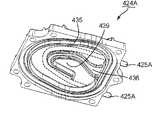
- FIG. 22 is a schematic perspective view of the lid piece 424A.
- the mounting structure of the heater 425A will be described with reference to FIGS.
- the lid piece 424A includes an inner shield wall 436 surrounded by the outer shield wall 435.
- the inner shield wall 436 has substantially the same shape as the inner chamber wall 432 of the main piece 423A.
- the inner shield wall 436 overlaps the inner chamber wall 432.
- a spiral flow path is formed in the chamber space 430. Since the area of the lower surface 434 surrounded by the inner shield wall 436 faces the inflow port 437 formed in the main piece 423A, it will be referred to as “opposing area 439” in the following description.
- the heater 425A is attached in the lid piece 424A so as to surround the facing region 439. If the flow rate of the water is adjusted so that the water flowing in from the inflow port 437 reaches the lid piece 424A, the opposing region 439 is particularly hot, so that instantaneous evaporation is achieved.
- the embodiment described above mainly includes the following configuration.
- a washing machine includes a storage tank that stores wash water for washing clothes, a first heater that heats the wash water, and a steam supply mechanism that supplies steam to the storage tank. And a controller for controlling the steam supply mechanism and the first heater. The controller operates the steam supply mechanism after stopping the first heater.
- the storage tank stores wash water for washing clothes.
- the first heater heats the washing water in the storage tank. Therefore, the temperature of the washing water rises efficiently in time as compared with the temperature rise technology that relies on steam.
- the control unit controls not only the first heater but also a steam supply mechanism that supplies steam to the storage tank. Since the control unit operates the steam supply mechanism after stopping the first heater, the washing water is appropriately kept warm. Therefore, the washing machine can exhibit a high cleaning ability over a long period of time.
- control unit may activate the first heater if the washing water exceeds a predetermined water level in the storage tub.
- the control unit operates the first heater, so that the washing water is warmed by the first heater in a short time.
- the washing machine may further include a detection element that detects the temperature of the washing water. If the temperature detected by the detection element exceeds the first threshold temperature, the control unit may stop the first heater.
- the control unit stops the first heater, so that excessive power consumption by the first heater is prevented. Since the control unit operates the steam supply mechanism after stopping the first heater, the washing water is appropriately kept warm. Therefore, the washing machine can exhibit a high cleaning ability over a long period of time.
- the steam supply mechanism includes a steam generator having a wall surface that defines a chamber for generating the steam, a second heater that heats the wall surface, a water supply mechanism that emits water to the wall surface, May be included.
- the control unit may operate the water supply mechanism after stopping the first heater.
- the control unit operates the water supply mechanism after stopping the first heater, so that water is emitted to the wall surface heated by the second heater.
- the water supplied from the water supply mechanism evaporates instantaneously, so that high-temperature steam flows into the storage tank at a high speed.
- the steam can efficiently transfer heat energy to the wash water.
- control unit may operate the steam generation mechanism and supply the steam to the storage tank.
- the control unit operates the steam generation mechanism and supplies steam to the storage tank. Heated.
- the water supply mechanism may include a water storage tank that stores the water and a pump that supplies the water from the water storage tank to the steam generator.
- the control unit may operate the pump after stopping the first heater.
- control unit since the control unit operates the pump after stopping the first heater, water is emitted to the wall surface heated by the second heater. As a result, the water supplied from the pump evaporates instantaneously, so that high-temperature steam flows into the storage tank at a high speed. Thus, steam can efficiently transfer heat energy to the wash water.
- control unit may operate the pump intermittently.
- control unit since the control unit operates the pump intermittently, a small amount of water is emitted to the wall surface. As a result, the water supplied from the pump evaporates instantaneously, so that high-temperature steam flows into the storage tank at a high speed. Thus, steam can efficiently transfer heat energy to the wash water.
- the water supply period in which the pump supplies the water from the water reservoir to the steam generator is greater than the period in which the pump is stopped. May be shorter.
- the water supply period during which the pump supplies water from the water storage tank to the steam generator is shorter than the period during which the pump is stopped. Therefore, the temperature of the wall surface is kept high by the second heater. As a result, the water supplied from the pump evaporates instantaneously, so that high-temperature steam flows into the storage tank at a high speed. Thus, the steam can efficiently transfer heat energy to the wash water.
- the principle of the above-described embodiment is preferably used for an apparatus for processing clothing using steam.
Landscapes
- Engineering & Computer Science (AREA)
- Textile Engineering (AREA)
- Detail Structures Of Washing Machines And Dryers (AREA)
- Control Of Washing Machine And Dryer (AREA)
Abstract
La présente invention concerne une machine à laver (110), qui comprend un récipient de logement (200) qui loge l'eau de lavage pour laver un vêtement, un premier élément chauffant (160) qui chauffe l'eau de lavage, un mécanisme de fourniture de vapeur (300) qui fournit de la vapeur au récipient de logement (200) et une unité de commande (122) qui commande le mécanisme de fourniture de vapeur (300) et le premier élément chauffant (160). L'unité de commande (122), après désactivation du premier élément chauffant (160), active le mécanisme de fourniture de vapeur (300).
Priority Applications (3)
| Application Number | Priority Date | Filing Date | Title |
|---|---|---|---|
| EP13800474.2A EP2860300B1 (fr) | 2012-06-06 | 2013-05-29 | Machine à laver |
| CN201380016302.1A CN104246054B (zh) | 2012-06-06 | 2013-05-29 | 洗衣机 |
| SI201330720T SI2860300T1 (sl) | 2012-06-06 | 2013-05-29 | Pralni stroj |
Applications Claiming Priority (2)
| Application Number | Priority Date | Filing Date | Title |
|---|---|---|---|
| JP2012128811A JP2013252239A (ja) | 2012-06-06 | 2012-06-06 | 洗濯機 |
| JP2012-128811 | 2012-06-06 |
Publications (1)
| Publication Number | Publication Date |
|---|---|
| WO2013183258A1 true WO2013183258A1 (fr) | 2013-12-12 |
Family
ID=49711666
Family Applications (1)
| Application Number | Title | Priority Date | Filing Date |
|---|---|---|---|
| PCT/JP2013/003408 Ceased WO2013183258A1 (fr) | 2012-06-06 | 2013-05-29 | Machine à laver |
Country Status (4)
| Country | Link |
|---|---|
| EP (1) | EP2860300B1 (fr) |
| JP (1) | JP2013252239A (fr) |
| SI (1) | SI2860300T1 (fr) |
| WO (1) | WO2013183258A1 (fr) |
Cited By (1)
| Publication number | Priority date | Publication date | Assignee | Title |
|---|---|---|---|---|
| US11293131B2 (en) | 2018-03-30 | 2022-04-05 | Midea Group Co., Ltd. | Appliance with hand held steam accessory |
Families Citing this family (2)
| Publication number | Priority date | Publication date | Assignee | Title |
|---|---|---|---|---|
| WO2020136248A1 (fr) * | 2018-12-27 | 2020-07-02 | Arcelik Anonim Sirketi | Lave-linge à fonction de lavage à la vapeur |
| US20260092409A1 (en) * | 2022-12-15 | 2026-04-02 | Lg Electronics Inc. | Clothing treatment apparatus and control method of clothing treatment apparatus |
Citations (5)
| Publication number | Priority date | Publication date | Assignee | Title |
|---|---|---|---|---|
| JP2006109886A (ja) * | 2004-10-12 | 2006-04-27 | Sanyo Electric Co Ltd | 洗濯機 |
| JP2007195942A (ja) * | 2006-01-26 | 2007-08-09 | Samsung Electronics Co Ltd | 蒸気発生装置を備えた洗濯機及びその制御方法 |
| EP1861534A1 (fr) | 2005-03-25 | 2007-12-05 | LG Electronics Inc. | Pulverisation de vapeur dans le tambour d'un lave-linge et procede de commande du cycle de lavage de ce lave-linge |
| JP2008534049A (ja) * | 2005-03-25 | 2008-08-28 | エルジー エレクトロニクス インコーポレイティド | 洗濯装置の洗濯方法 |
| EP2031114A1 (fr) | 2007-08-31 | 2009-03-04 | Whirlpool Corporation | Procédé de détection d'anomalie dans un appareil de traitement de tissus doté d'un générateur de vapeur |
Family Cites Families (5)
| Publication number | Priority date | Publication date | Assignee | Title |
|---|---|---|---|---|
| JPS4836785B1 (fr) * | 1970-12-11 | 1973-11-07 | ||
| KR101022226B1 (ko) * | 2004-01-06 | 2011-03-17 | 삼성전자주식회사 | 세탁기 및 그 제어방법 |
| KR100565251B1 (ko) * | 2004-07-19 | 2006-03-30 | 엘지전자 주식회사 | 드럼세탁기의 절수세탁방법 |
| JP2007111396A (ja) * | 2005-10-24 | 2007-05-10 | Sharp Corp | 洗濯乾燥機 |
| KR20080076652A (ko) * | 2007-02-16 | 2008-08-20 | 삼성전자주식회사 | 세탁기 및 그 제어방법 |
-
2012
- 2012-06-06 JP JP2012128811A patent/JP2013252239A/ja active Pending
-
2013
- 2013-05-29 EP EP13800474.2A patent/EP2860300B1/fr not_active Not-in-force
- 2013-05-29 WO PCT/JP2013/003408 patent/WO2013183258A1/fr not_active Ceased
- 2013-05-29 SI SI201330720T patent/SI2860300T1/sl unknown
Patent Citations (5)
| Publication number | Priority date | Publication date | Assignee | Title |
|---|---|---|---|---|
| JP2006109886A (ja) * | 2004-10-12 | 2006-04-27 | Sanyo Electric Co Ltd | 洗濯機 |
| EP1861534A1 (fr) | 2005-03-25 | 2007-12-05 | LG Electronics Inc. | Pulverisation de vapeur dans le tambour d'un lave-linge et procede de commande du cycle de lavage de ce lave-linge |
| JP2008534049A (ja) * | 2005-03-25 | 2008-08-28 | エルジー エレクトロニクス インコーポレイティド | 洗濯装置の洗濯方法 |
| JP2007195942A (ja) * | 2006-01-26 | 2007-08-09 | Samsung Electronics Co Ltd | 蒸気発生装置を備えた洗濯機及びその制御方法 |
| EP2031114A1 (fr) | 2007-08-31 | 2009-03-04 | Whirlpool Corporation | Procédé de détection d'anomalie dans un appareil de traitement de tissus doté d'un générateur de vapeur |
Non-Patent Citations (1)
| Title |
|---|
| See also references of EP2860300A4 |
Cited By (1)
| Publication number | Priority date | Publication date | Assignee | Title |
|---|---|---|---|---|
| US11293131B2 (en) | 2018-03-30 | 2022-04-05 | Midea Group Co., Ltd. | Appliance with hand held steam accessory |
Also Published As
| Publication number | Publication date |
|---|---|
| EP2860300B1 (fr) | 2017-05-03 |
| EP2860300A1 (fr) | 2015-04-15 |
| EP2860300A4 (fr) | 2015-08-05 |
| JP2013252239A (ja) | 2013-12-19 |
| CN104246054A (zh) | 2014-12-24 |
| SI2860300T1 (sl) | 2017-10-30 |
Similar Documents
| Publication | Publication Date | Title |
|---|---|---|
| JP6244536B2 (ja) | 衣類処理装置 | |
| CN104204332B (zh) | 衣物处理装置 | |
| JP6074922B2 (ja) | 衣類処理装置 | |
| WO2013183258A1 (fr) | Machine à laver | |
| CN104185701B (zh) | 衣物处理装置 | |
| CN103459697B (zh) | 衣物处理装置 | |
| JP2014054400A (ja) | 衣類処理装置 | |
| JP2014171561A (ja) | 衣類処理装置 | |
| CN103443345B (zh) | 衣物处理装置 | |
| JP2013208248A (ja) | 衣類処理装置 | |
| JP2014004054A (ja) | 衣類処理装置 | |
| JP2014004056A (ja) | 衣類処理装置 | |
| JP2014004059A (ja) | 衣類処理装置 | |
| CN103502520B (zh) | 衣物处理装置 | |
| CN104246054B (zh) | 洗衣机 | |
| JP2013208252A (ja) | 衣類処理装置 | |
| CN103476981B (zh) | 衣物处理装置 | |
| JP2014033845A (ja) | 衣類処理装置 | |
| JP2018134263A (ja) | 衣類処理装置 | |
| JP2014050506A (ja) | 衣類処理装置 | |
| JP2014023674A (ja) | 衣類処理装置 | |
| JP2017029499A (ja) | 衣類処理装置 |
Legal Events
| Date | Code | Title | Description |
|---|---|---|---|
| 121 | Ep: the epo has been informed by wipo that ep was designated in this application |
Ref document number: 13800474 Country of ref document: EP Kind code of ref document: A1 |
|
| REEP | Request for entry into the european phase |
Ref document number: 2013800474 Country of ref document: EP |
|
| WWE | Wipo information: entry into national phase |
Ref document number: 2013800474 Country of ref document: EP |
|
| NENP | Non-entry into the national phase |
Ref country code: DE |