WO2013183281A1 - Connecteur pour la mesure d'informations biologiques, et dispositif de mesure d'informations biologiques à l'aide de celui-ci - Google Patents
Connecteur pour la mesure d'informations biologiques, et dispositif de mesure d'informations biologiques à l'aide de celui-ci Download PDFInfo
- Publication number
- WO2013183281A1 WO2013183281A1 PCT/JP2013/003498 JP2013003498W WO2013183281A1 WO 2013183281 A1 WO2013183281 A1 WO 2013183281A1 JP 2013003498 W JP2013003498 W JP 2013003498W WO 2013183281 A1 WO2013183281 A1 WO 2013183281A1
- Authority
- WO
- WIPO (PCT)
- Prior art keywords
- biological information
- frame
- information measuring
- surface opening
- connection
- Prior art date
- Legal status (The legal status is an assumption and is not a legal conclusion. Google has not performed a legal analysis and makes no representation as to the accuracy of the status listed.)
- Ceased
Links
Images






Classifications
-
- H—ELECTRICITY
- H01—ELECTRIC ELEMENTS
- H01R—ELECTRICALLY-CONDUCTIVE CONNECTIONS; STRUCTURAL ASSOCIATIONS OF A PLURALITY OF MUTUALLY-INSULATED ELECTRICAL CONNECTING ELEMENTS; COUPLING DEVICES; CURRENT COLLECTORS
- H01R13/00—Details of coupling devices of the kinds covered by groups H01R12/70 or H01R24/00 - H01R33/00
- H01R13/46—Bases; Cases
- H01R13/502—Bases; Cases composed of different pieces
- H01R13/504—Bases; Cases composed of different pieces different pieces being moulded, cemented, welded, e.g. ultrasonic welding, or swaged together
-
- A—HUMAN NECESSITIES
- A61—MEDICAL OR VETERINARY SCIENCE; HYGIENE
- A61B—DIAGNOSIS; SURGERY; IDENTIFICATION
- A61B5/00—Measuring for diagnostic purposes; Identification of persons
- A61B5/145—Measuring characteristics of blood in vivo, e.g. gas concentration or pH-value ; Measuring characteristics of body fluids or tissues, e.g. interstitial fluid or cerebral tissue
- A61B5/14532—Measuring characteristics of blood in vivo, e.g. gas concentration or pH-value ; Measuring characteristics of body fluids or tissues, e.g. interstitial fluid or cerebral tissue for measuring glucose, e.g. by tissue impedance measurement
-
- G—PHYSICS
- G01—MEASURING; TESTING
- G01N—INVESTIGATING OR ANALYSING MATERIALS BY DETERMINING THEIR CHEMICAL OR PHYSICAL PROPERTIES
- G01N27/00—Investigating or analysing materials by the use of electric, electrochemical, or magnetic means
- G01N27/26—Investigating or analysing materials by the use of electric, electrochemical, or magnetic means by investigating electrochemical variables; by using electrolysis or electrophoresis
- G01N27/28—Electrolytic cell components
- G01N27/30—Electrodes, e.g. test electrodes; Half-cells
- G01N27/327—Biochemical electrodes, e.g. electrical or mechanical details for in vitro measurements
- G01N27/3271—Amperometric enzyme electrodes for analytes in body fluids, e.g. glucose in blood
- G01N27/3273—Devices therefor, e.g. test element readers, circuitry
-
- G—PHYSICS
- G01—MEASURING; TESTING
- G01N—INVESTIGATING OR ANALYSING MATERIALS BY DETERMINING THEIR CHEMICAL OR PHYSICAL PROPERTIES
- G01N33/00—Investigating or analysing materials by specific methods not covered by groups G01N1/00 - G01N31/00
- G01N33/48—Biological material, e.g. blood, urine; Haemocytometers
- G01N33/483—Physical analysis of biological material
- G01N33/487—Physical analysis of biological material of liquid biological material
- G01N33/48785—Electrical and electronic details of measuring devices for physical analysis of liquid biological material not specific to a particular test method, e.g. user interface or power supply
-
- H—ELECTRICITY
- H01—ELECTRIC ELEMENTS
- H01R—ELECTRICALLY-CONDUCTIVE CONNECTIONS; STRUCTURAL ASSOCIATIONS OF A PLURALITY OF MUTUALLY-INSULATED ELECTRICAL CONNECTING ELEMENTS; COUPLING DEVICES; CURRENT COLLECTORS
- H01R12/00—Structural associations of a plurality of mutually-insulated electrical connecting elements, specially adapted for printed circuits, e.g. printed circuit boards [PCB], flat or ribbon cables, or like generally planar structures, e.g. terminal strips, terminal blocks; Coupling devices specially adapted for printed circuits, flat or ribbon cables, or like generally planar structures; Terminals specially adapted for contact with, or insertion into, printed circuits, flat or ribbon cables, or like generally planar structures
- H01R12/70—Coupling devices
- H01R12/7094—Coupling devices with switch operated by engagement of PCB
-
- H—ELECTRICITY
- H01—ELECTRIC ELEMENTS
- H01R—ELECTRICALLY-CONDUCTIVE CONNECTIONS; STRUCTURAL ASSOCIATIONS OF A PLURALITY OF MUTUALLY-INSULATED ELECTRICAL CONNECTING ELEMENTS; COUPLING DEVICES; CURRENT COLLECTORS
- H01R13/00—Details of coupling devices of the kinds covered by groups H01R12/70 or H01R24/00 - H01R33/00
- H01R13/648—Protective earth or shield arrangements on coupling devices, e.g. anti-static shielding
- H01R13/658—High frequency shielding arrangements, e.g. against EMI [Electro-Magnetic Interference] or EMP [Electro-Magnetic Pulse]
- H01R13/6591—Specific features or arrangements of connection of shield to conductive members
- H01R13/6594—Specific features or arrangements of connection of shield to conductive members the shield being mounted on a PCB and connected to conductive members
-
- H—ELECTRICITY
- H01—ELECTRIC ELEMENTS
- H01R—ELECTRICALLY-CONDUCTIVE CONNECTIONS; STRUCTURAL ASSOCIATIONS OF A PLURALITY OF MUTUALLY-INSULATED ELECTRICAL CONNECTING ELEMENTS; COUPLING DEVICES; CURRENT COLLECTORS
- H01R2201/00—Connectors or connections adapted for particular applications
- H01R2201/12—Connectors or connections adapted for particular applications for medicine and surgery
Definitions
- the present invention relates to a biological information measuring connector for measuring biological information such as blood glucose level from blood and a biological information measuring apparatus using the same.
- this type of biological information measuring device includes a main body case having a sensor mounting portion and a biological information measuring connector provided inside the sensor mounting portion of the main body case.
- the biological information measuring connector is formed of a synthetic resin and has a quadrangular frame having an upper surface opening and a lower surface opening. And between the upper surface opening portion and the lower surface opening portion on one side of the frame body, the rear end is pulled out to the outside of the frame body, the middle portion is embedded in the frame body, and the tip is disposed inside the frame body. A connection terminal is provided. Furthermore, the sensor insertion port provided between the upper surface opening part of the other side which opposes one side of a frame, and a lower surface opening part is provided.
- the biological information measuring connector is mounted on a connection board in the main body case (see, for example, Patent Document 1).
- the sensor is electrically connected to the connection terminal of the biological information measuring connector provided inside the main body case.
- This biological information measuring connector has a connection terminal integrally formed with a frame body made of synthetic resin.
- the frame body is opened on the upper surface in order to hold the connection terminals from above and below for positioning of the connection terminals and because the tip of the connection terminal is not embedded in the resin. And a lower surface opening.
- the biological information measurement connector is stored via the upper surface opening when the biological information measurement connector is stored or when the biological information measurement connector is mounted on the connection board of the biological information measurement device. Foreign matter enters the connection terminal area. As a result, connection failure between the connection terminal and the sensor may occur.
- the present invention is a quadrangular frame formed of synthetic resin and having an upper surface opening and a lower surface opening, and is provided between the upper surface opening and the lower surface opening on one side of the frame, and the rear end is a frame
- the connecting terminal is drawn out to the outside of the frame, the middle part is embedded in the frame, and the tip is disposed inside the frame.
- the sensor insertion port provided between the upper surface opening part and lower surface opening part of the other side which opposes one side of a frame is provided.
- a metal top cover that covers the top opening is attached to the top opening of the frame, and the sensor insertion port side portion of the top cover is inserted into a bent piece insertion slot provided on the other side of the frame.
- the ground connection piece is formed by extending the outer sides of the left and right frames from the upper surface to the lower surface of the upper body of the upper surface cover. It is set as the structure which provided.
- the present invention is equipped with a metal upper surface cover that covers the upper surface opening, when storing the biological information measurement connector, or when mounting this biological information measurement connector on the connection substrate of the biological information measurement device, Foreign matter does not enter the connection terminal portion through the upper surface opening. As a result, it is possible to prevent a connection failure between the connection terminal and the sensor.
- a bent piece to be inserted into a bent piece insertion port provided on the other side of the frame is provided on the sensor insertion port side portion of the upper cover, and the left and right sides of the upper cover are provided on the left and right sides of the frame. Since a ground connection piece extending from the upper surface of the frame body toward the lower surface is provided at a portion facing the left and right sides, damage due to static electricity can be prevented.
- a sensor when measuring biological information, a sensor is inserted into the frame body from the sensor insertion port, and then connected to the connection terminal. If the human body having this sensor is charged with a high voltage, the connection terminal is connected via the sensor. Alternatively, static electricity may flow through a measurement unit connected to the connection terminal. As a result, there is a risk of damaging the measurement unit and the like.
- a bent piece to be inserted into a bent piece insertion port provided on the other side of the frame body is provided on the sensor insertion port side portion of the upper surface cover, and the left and right sides of the frame body of the upper surface cover are provided.
- a ground connection piece is provided in a portion facing the side of the frame. The ground connection piece extends the outside of the left and right frames from the upper surface to the lower surface of the frame. For this reason, when the sensor is inserted into the sensor insertion opening, the high voltage is applied from the bent piece insertion opening portion of the frame body to the upper surface via the bent piece of the upper surface cover inserted into the bending piece insertion opening. Static electricity will flow to the grounding piece of the cover.
- FIG. 1 is a perspective view of a biological information measuring apparatus according to a first embodiment of the present invention.
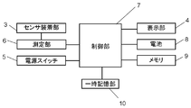
- FIG. 2 is a block diagram of the biological information measuring apparatus according to the first embodiment of the present invention.
- FIG. 3 is a perspective view of a biological information measuring connector used in the biological information measuring apparatus according to the first embodiment of the present invention.
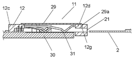
- FIG. 4 is a cross-sectional view of the biological information measuring connector according to the first embodiment of the present invention.
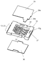
- FIG. 5 is an exploded perspective view of the biological information measuring connector according to the first embodiment of the present invention.
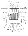
- FIG. 6 is a plan view of the biological information measuring connector according to the first embodiment of the present invention.
- FIG. 7 is a rear view of the biological information measuring connector according to the first embodiment of the present invention.
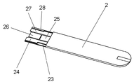
- FIG. 8 is a perspective view of a sensor inserted into the biological information measuring connector in the first embodiment of the present invention.
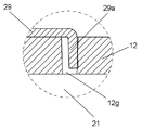
- FIG. 9 is a cross-sectional view of the main part of the biological information measuring connector according to the first embodiment of the present invention.
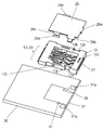
- FIG. 10 is an exploded perspective view of the biological information measuring connector used in the biological information measuring apparatus according to the second embodiment of the present invention.
- FIG. 11 is an exploded perspective view of the biological information measuring connector used in the biological information measuring apparatus according to the third embodiment of the present invention.
- FIG. 12 is a perspective view of a biological information measuring connector according to the fourth embodiment of the present invention.
- FIG. 13 is a rear view of the biological information measuring connector according to the fourth embodiment of the present invention.
- FIG. 14 is an exploded perspective view of the biological information measuring connector according to the fourth embodiment of the present invention.
- a main body case 1 of a measuring instrument for measuring a blood sugar level from blood which is an example of a biological information measuring device, is formed in a substantially rectangular parallelepiped shape.
- a sensor mounting portion 3 for inserting a blood glucose level sensor 2, which is an example of a biological information measurement sensor is provided on one end side of the main body case 1.
- a display unit 4 and a power switch 5 are provided on the upper surface of the main body case 1.
- a measurement unit 6 electrically connected to the sensor mounting unit 3 and a control unit 7 connected to the measurement unit 6 are disposed inside the main body case 1.
- the control unit 7 is connected to the display unit 4, the power switch 5, and the battery 8, and is further connected to a memory 9 including a ROM in which a control program of the control unit 7 is recorded.
- the memory 9 also stores the measurement procedure of the measurement unit 6.
- a temporary storage unit 10 is connected to the control unit 7 as a temporary storage unit for work performed by the control unit 7.
- a biological information measuring connector 11 shown in FIGS. 3 to 5 is arranged on the rear side of the sensor mounting portion 3 in the main body case 1.
- the biological information measuring connector 11 is formed of a synthetic resin and has a rectangular frame 12 having a rectangular upper surface opening 12a and a rectangular lower surface opening 12b. Between the upper surface opening 12 a and the lower surface opening 12 b of one side 12 c of the frame body 12, the rear end is pulled out to the outside of the frame body 12, the middle portion is embedded in the frame body 12, and the front end is inside the frame body 12. A plurality of connecting terminals 13 to 20 are provided.
- the biological information measuring connector 11 includes a horizontally elongated sensor insertion port 21 between the upper surface opening 12a and the lower surface opening 12b on the other side 12d facing the one side 12c of the frame 12.
- the sensor insertion port 21 is a through hole having a horizontally long shape for inserting the plate-like blood glucose level sensor 2 and preventing water and dust from entering.
- the central portion of the frame body 12 penetrates from the rectangular upper surface opening 12a to the rectangular lower surface opening 12b, and a thin plate-like space is formed here.
- the frame body 12 is integrally formed with the connection terminals 13 to 20 and the sensor insertion port 21 by upper and lower molds (not shown).
- connection terminals 13 to 20 are arranged on the lower mold (not shown) in a state where they are horizontally separated from each other by a predetermined distance, and the upper mold (not shown) is covered in this state. If the synthetic resin is poured into these upper and lower molds, the frame body 12 shown in FIGS. 3 to 5 is integrally formed.
- connection terminals 13 to 20 and the frame body 12 in order to integrally mold the connection terminals 13 to 20 and the frame body 12, it is necessary to use a rectangular frame body 12 having an upper surface opening 12a and a lower surface opening 12b.
- connection terminals 13 to 20 are horizontally separated from each other by a predetermined distance, and the middle portion is buried in the side 12c of the frame body 12. .
- the rear ends of the connection terminals 13 to 20 are drawn out to the outside of one side 12 c of the frame body 12, and the leading ends are drawn out to the inside of the frame body 12.
- the other side 12d provided with the sensor insertion port 21 is the left and right sides of the frame 12 at the left and right positions of the sensor insertion port 21. 12e and 12f.
- the left and right sides 12e and 12f of the frame body 12 have a sensor insertion guide surface 22 on the inner surface side between the upper surface opening 12a and the lower surface opening 12b.
- the sensor insertion guide surface 22 has the same width as the sensor insertion port 21 as shown in FIG. That is, if the rear end side of the blood glucose level sensor 2 in FIG. 1 is inserted from the sensor insertion port 21, the left and right long sides of the blood glucose level sensor 2 are guided by the left and right sensor insertion guide surfaces 22 and guided backward. Will be.
- the blood glucose level sensor 2 includes connection electrodes 23 to 28 as shown in FIG. Therefore, if the rear end side of the blood glucose level sensor 2 is inserted from the sensor insertion port 21, the connection electrode 23 is connected to the connection terminal 20 shown in FIG. 6, and the rear end side of the connection electrode 24 is connected to the connection terminal. 19, and the distal end side of the connection electrode 24 is connected to the connection terminal 18.
- connection electrode 16 is connected to the connection electrode 25, and the connection terminal 17 is connected to the connection electrode 26.
- connection terminal 14 is connected to the rear end side of the connection electrode 27, the connection terminal 15 is connected to the front end side of the connection electrode 27, and the connection terminal 13 is connected to the connection electrode 28. It has become.
- connection electrodes 23 to 28 are arranged adjacent to each other on the rear end side of the blood glucose level sensor 2 as shown in FIG. It is to connect the terminals 13 to 20 appropriately.
- the sensor insertion port 21 is integrally provided in the frame 12 in which the connection terminals 13 to 20 are integrated, and the sensor insertion guide surfaces 22 are provided on the left and right sides thereof. For this reason, if the rear end side of the blood glucose level sensor 2 is inserted into the sensor insertion port 21, the rear end side of the blood glucose level sensor 2 is guided by the left and right sensor insertion guide surfaces 22 and appropriately guided rearward. .
- connection electrodes 23 to 28 of the blood glucose level sensor 2 can be appropriately connected to the connection terminals 13 to 20.
- the contact surface of the upper mold and the lower mold is provided below the sensor insertion guide surface 22. That is, since a line called a parting line is formed on the contact surface between the upper mold and the lower mold, the parting line is set below the sensor insertion guide surface 22. This prevents the parting line from contacting the left and right long sides of the blood glucose level sensor 2 when the blood glucose level sensor 2 is inserted.
- this parting line is arranged below the sensor insertion guide surface 22.
- connection terminals 13 to 20 When the upper surface opening 12a is present in the frame 12, when the biological information measuring connector 11 is stored or when the biological information measuring connector 11 is mounted on the connection board 30 of the biological information measuring device, Foreign matter enters the connection terminals 13 to 20 through the upper surface opening 12a. As a result, there is a risk that connection failure between the connection terminals 13 to 20 and the blood glucose level sensor 2 may occur.
- a metal upper surface cover 29 that covers the entire surface of the upper surface opening 12 a is attached to the upper surface opening 12 a of the frame 12.
- the folded piece inserted into the folded piece insertion port 12g provided on the other side 12d of the frame 12. 29a is provided.
- the bent piece 29a is formed by bending the end of the top cover 29 downward.
- the bent piece 29a is inserted into the bent piece insertion port 12g provided on the upper surface of the sensor insertion port 21, as shown in FIGS.
- the bent piece insertion port 12g is provided on the upper surface side of the horizontally long sensor insertion port 21.
- the outer sides of the left and right sides 12 e and 12 f of the frame body 12 are arranged on the portion of the top cover 29 facing the left and right sides 12 e and 12 f of the frame body 12.
- the ground connection piece 29b extended from the upper surface toward the lower surface was provided by bending.
- the ground connection piece 29b comes into contact with a ground pattern 31a projecting left and right from the conductive pattern 31 of the connection substrate 30, and is then electrically and mechanically connected by a conductive adhesive.
- the measuring unit 6 connected to the connection terminals 13 to 20 or the connection terminals 13 to 20 by static electricity. Will not be damaged.
- the blood glucose level sensor 2 is inserted into the frame body 12 from the sensor insertion port 21 and then connected to the connection terminals 13 to 20.
- the human body having the blood glucose level sensor 2 is charged with a high voltage, static electricity flows through the blood glucose level sensor 2 to the connection terminals 13 to 20 or the measurement unit 6 connected to the connection terminals 13 to 20. May damage them.
- the bent piece 29a to be inserted into the bent piece insertion port 12g provided on the other side 12d of the frame 12 is provided on the sensor insertion port 21 side portion of the top cover 29. Further, in the portion of the upper surface cover 29 facing the left and right sides 12e and 12f of the frame body 12, the outer sides of the left and right sides 12e and 12f of the frame body 12 are directed from the upper surface to the lower surface of the frame body 12.
- An extended ground connection piece 29b is provided.
- the ground connection piece 29b is electrically and mechanically connected to the ground pattern 31a protruding left and right from the conductive pattern 31 of the connection substrate 30 by a conductive adhesive.
- the conductive pattern 31 is connected to the earth line.
- the frame 12 since the frame 12 is formed of a synthetic resin, the frame body 12 generally exhibits insulating properties. However, a current can be applied to a high voltage such as the static electricity described above, and thereby the blood sugar level can be increased. Static electricity can flow to the sensor 2, the frame 12, the bent piece 29a, the upper surface cover 29, the ground connection piece 29b, and the ground pattern 31a.
- the ground pattern 31a is formed integrally with the conductive pattern 31, but the ground pattern 31a and the conductive pattern 31 may be formed separately on the connection substrate 30.
- the upper surface cover 29 made of metal has a flat upper surface, and the upper surface side of the upper surface cover 29 serves as a suction portion for a mounting nozzle (not shown). Therefore, the biological information measuring connector 11 of the present embodiment can be adsorbed by a mounting nozzle (not shown) and can be mounted on the connection board 30 by a mounting machine.
- the upper cover 29 is made of silver metal and the frame 12 is made of black synthetic resin, so that the color of the upper cover 29 and the frame 12 and the light reflectance are different.
- the upper surface of the upper surface cover 29 (that is, the mounting nozzle suction portion) is made smaller than the upper surface of the frame body 12 as shown in FIG. 3 so that the upper surface of the upper surface of the upper surface cover 29 is covered by the upper surface of the frame body 12. did.
- the silver mounting nozzle suction part is surrounded by the black frame 12, and a control unit (not shown) for controlling the mounting nozzle determines the position of the mounting nozzle suction part by image processing, for example. In some cases, the position of the mounting nozzle suction portion is easy to recognize.
- a conductive pattern 31 is provided on the upper surface of the connection body 30 on which the frame body 12 is mounted, which faces the lower surface opening 12 b of the frame body 12. ing.
- the conductive pattern 31 is formed of, for example, gold plating.
- the tip ends of the connection terminals 13 to 20 are all on this side.
- the conductive pattern 31 is in contact with the conductive pattern 31.
- connection terminals 13 to 20 it can be determined whether or not each of the connection terminals 13 to 20 is urged downward.
- the conductive pattern 31 is connected to the ground line. For example, if a signal is applied to the rear end side of the connection terminal 13, the signal flows from the connection terminal 13 to the conductive pattern 31. It can be determined that it is properly biased downward.
- the contact resistance is less than 50 m ⁇ , it can be determined that the connection terminals 13 to 20 are normally in contact with the conductive pattern 31. If the contact resistance is in the range of 50 m ⁇ or more and less than 1 M ⁇ , it can be determined that the conductive terminal is in an abnormal state such as a conductive foreign substance adhering to the connection terminals 13 to 20 or a contact being oxidized. If the contact resistance is 1 M ⁇ or more, it can be determined that the connection terminals 13 to 20 are broken or a non-conductive foreign substance is adhered, for example, to be in an open state.
- the conductive pattern 31 in this way, if the rear end of the blood glucose level sensor 2 is inserted, all the continuity of the connection terminals 13 to 20 is cut off, so that the blood glucose level sensor 2 is properly inserted. It is also possible to detect the state.
- a detection switch 32 for detecting the insertion of the blood glucose level sensor 2 is provided on the back side of the frame body 12, and the operation body 33 disposed in front of the detection switch 32 is connected to the rear end side of the blood glucose level sensor 2. The insertion of the blood glucose level sensor 2 is appropriately detected by pressing the button.
- the insertion detection terminal 34 and the insertion detection terminal 35 of the detection switch 32 are drawn out of the frame 12.
- the upper surface opening 12a and the lower surface opening 12b are provided in the frame 12 of the biological information measuring connector 11 itself, so that the connection terminals 13 to 20 can be connected with the upper and lower molds.
- the sensor insertion port 21 is also integrally formed.
- a metal upper surface cover 29 that covers the entire surface of the upper surface opening 12a is attached to the upper surface opening 12a of the frame 12.
- FIG. 10 shows a biological information measuring connector according to the second embodiment of the present invention.
- the same components as those of the biological information measuring connector according to the first embodiment are denoted by the same reference numerals and described. Omitted.
- the operation check cover 36 is disposed in the lower surface opening 12 b of the frame 12. That is, in the first embodiment, this operation check cover 36 is provided instead of the conductive pattern 31 provided on the upper surface of the connection substrate 30. For this reason, the operation confirmation cover 36 is made of metal and connected to the ground line.
- FIG. 11 shows a biological information measuring connector according to the third embodiment of the present invention.
- the same components as those of the biological information measuring connector according to the first embodiment are denoted by the same reference numerals and description thereof is omitted.
- the conductive pattern 31 in FIG. 1 is divided by providing slits, and the individual conductive patterns 31b to 31i are opposed to each terminal of the connection terminals 13 to 20 independently. It is arranged.
- connection terminal 13 is in contact with the connection terminal 13 and the conductive pattern 31 c is in contact with the connection terminal 14, but the connection terminal 13 is deformed by an insertion operation of the blood glucose level sensor 2 or the like.
- the connection terminal 13 may be in contact with the conductive pattern 31c instead of the conductive pattern 31b with which the connection terminal 13 is originally in contact.
- connection terminal 13 is electrically connected to the conductive pattern 31c instead of the conductive pattern 31b, by detecting this conduction, it is detected that the position of the connection terminal 13 is an inappropriate position. Can do.
- connection terminal 13 is not properly connected to the connection electrode 28 of the blood glucose level sensor 2 before the blood glucose level sensor 2 is inserted into the biological information measuring connector 11.
- the ground connection piece 29b of the upper surface cover 29 is electrically and mechanically connected to the ground pattern 31a provided outside the conductive pattern 31d and the conductive pattern 31i.
- (Fourth embodiment) 12 to 14 show a fourth embodiment of the present invention.
- a locking piece 29c to the frame body 12 is formed by bending downward on the connection terminals 13 to 20 side of the top cover 29 used in the first embodiment.
- the sensor insertion port 21 side of the top cover 29 can be integrated by press-fitting the ground connection piece 29b into the locking portion 12h (FIG. 14) of the frame body 12, but the connection terminal of the top cover 29 There is a possibility that the 13th to 20th sides will float from the frame 12.
- the locking piece 29c is provided on the connection terminal 13 to 20 side of the top cover 29, and the locking projection 12i of the frame 12 is inserted into the locking hole 29d.
- the connection terminals 13 to 20 are also integrated with the frame 12.
- the upper surface cover 29 serves as a mounting nozzle suction surface, it is preferable that the entire upper surface cover 29 is integrated with the frame body 12.
- the sensor insertion port 21 of the upper surface cover 29 is used as a countermeasure.
- the ground connection piece 29b is provided on the side, and the locking piece 29c is provided on the connection terminals 13-20 side.
- positioning protrusions 12j and 12k are provided on the left and right sides on the lower surface side of the frame 12 as shown in FIG. Further, as shown in FIG. 14, a through hole 37 and a through hole 38 are provided on both sides of the conductive pattern 31 of the connection substrate 30.
- the positioning protrusion 12 j of the frame body 12 is inserted into the through hole 37 of the connection board 30. Then, if the positioning protrusion 12k is inserted into the through hole 38 of the connection board 30, the biological information measuring connector 11 can be mounted at an appropriate position on the connection board 30.
- the ground connection piece 29b of the upper surface cover 29 is securely brought into contact with the ground pattern 31a so that the above-described countermeasure against static electricity is taken.
- the present invention is expected to be widely used as a biological information measuring connector and a biological information measuring device using the same.
Landscapes
- Health & Medical Sciences (AREA)
- Life Sciences & Earth Sciences (AREA)
- Engineering & Computer Science (AREA)
- Physics & Mathematics (AREA)
- Biomedical Technology (AREA)
- Chemical & Material Sciences (AREA)
- Biophysics (AREA)
- General Health & Medical Sciences (AREA)
- Molecular Biology (AREA)
- Pathology (AREA)
- Analytical Chemistry (AREA)
- Immunology (AREA)
- General Physics & Mathematics (AREA)
- Biochemistry (AREA)
- Hematology (AREA)
- Urology & Nephrology (AREA)
- Medicinal Chemistry (AREA)
- Food Science & Technology (AREA)
- Human Computer Interaction (AREA)
- Public Health (AREA)
- Emergency Medicine (AREA)
- Veterinary Medicine (AREA)
- Medical Informatics (AREA)
- Heart & Thoracic Surgery (AREA)
- Optics & Photonics (AREA)
- Animal Behavior & Ethology (AREA)
- Surgery (AREA)
- Chemical Kinetics & Catalysis (AREA)
- Electrochemistry (AREA)
- Measurement Of The Respiration, Hearing Ability, Form, And Blood Characteristics Of Living Organisms (AREA)
Abstract
Priority Applications (2)
| Application Number | Priority Date | Filing Date | Title |
|---|---|---|---|
| US14/388,243 US9214753B2 (en) | 2012-06-05 | 2013-06-04 | Connector for biological information measurement, and biological information measurement device using same |
| JP2014519837A JP5864737B2 (ja) | 2012-06-05 | 2013-06-04 | 生体情報測定用コネクタと、それを用いた生体情報測定装置 |
Applications Claiming Priority (4)
| Application Number | Priority Date | Filing Date | Title |
|---|---|---|---|
| JP2012-127641 | 2012-06-05 | ||
| JP2012127641 | 2012-06-05 | ||
| JP2013-086342 | 2013-04-17 | ||
| JP2013086342 | 2013-04-17 |
Publications (1)
| Publication Number | Publication Date |
|---|---|
| WO2013183281A1 true WO2013183281A1 (fr) | 2013-12-12 |
Family
ID=49711687
Family Applications (1)
| Application Number | Title | Priority Date | Filing Date |
|---|---|---|---|
| PCT/JP2013/003498 Ceased WO2013183281A1 (fr) | 2012-06-05 | 2013-06-04 | Connecteur pour la mesure d'informations biologiques, et dispositif de mesure d'informations biologiques à l'aide de celui-ci |
Country Status (3)
| Country | Link |
|---|---|
| US (1) | US9214753B2 (fr) |
| JP (2) | JP5864737B2 (fr) |
| WO (1) | WO2013183281A1 (fr) |
Cited By (1)
| Publication number | Priority date | Publication date | Assignee | Title |
|---|---|---|---|---|
| JP2016101510A (ja) * | 2012-06-05 | 2016-06-02 | パナソニックヘルスケアホールディングス株式会社 | 生体情報測定用コネクタと、それを用いた生体情報測定装置 |
Citations (7)
| Publication number | Priority date | Publication date | Assignee | Title |
|---|---|---|---|---|
| JP2006511788A (ja) * | 2002-04-25 | 2006-04-06 | ホーム ダイアグノスティックス,インコーポレーテッド | 血糖を検出するためのシステム及び方法 |
| JP2009178367A (ja) * | 2008-01-31 | 2009-08-13 | Sumitomo Electric Ind Ltd | バイオセンサ測定装置 |
| JP2009534635A (ja) * | 2006-04-21 | 2009-09-24 | エフ ホフマン−ラ ロッシュ アクチェン ゲゼルシャフト | 生物学的検査システム |
| JP2010520463A (ja) * | 2007-03-02 | 2010-06-10 | アイ−センス インコーポレイテッド | 電気化学的バイオセンサ測定システム |
| WO2011094315A1 (fr) * | 2010-01-28 | 2011-08-04 | Abbott Diabetes Care Inc. | Port de bandelette réactive universel |
| JP2011528437A (ja) * | 2008-07-17 | 2011-11-17 | アボット ダイアベティス ケア インコーポレイテッド | 測定デバイス用ストリップコネクタ |
| JP2012018930A (ja) * | 2011-09-06 | 2012-01-26 | Smk Corp | ヒンジカバー式メモリカードコネクタ |
Family Cites Families (9)
| Publication number | Priority date | Publication date | Assignee | Title |
|---|---|---|---|---|
| US6616819B1 (en) | 1999-11-04 | 2003-09-09 | Therasense, Inc. | Small volume in vitro analyte sensor and methods |
| US6964871B2 (en) | 2002-04-25 | 2005-11-15 | Home Diagnostics, Inc. | Systems and methods for blood glucose sensing |
| US6743635B2 (en) | 2002-04-25 | 2004-06-01 | Home Diagnostics, Inc. | System and methods for blood glucose sensing |
| ATE394142T1 (de) | 2004-01-27 | 2008-05-15 | Goldfire Sprl | Biegsame wand mit feuerbeständigen eigenschaften |
| JP2006286601A (ja) | 2005-03-11 | 2006-10-19 | Alps Electric Co Ltd | カード用コネクタ装置 |
| JP2011502255A (ja) | 2007-10-26 | 2011-01-20 | ジョンソン・エンド・ジョンソン株式会社 | テストストリップ射出機構 |
| WO2013105508A1 (fr) * | 2012-01-13 | 2013-07-18 | パナソニック株式会社 | Appareil de mesure d'informations biologiques |
| WO2013183281A1 (fr) * | 2012-06-05 | 2013-12-12 | パナソニック株式会社 | Connecteur pour la mesure d'informations biologiques, et dispositif de mesure d'informations biologiques à l'aide de celui-ci |
| WO2014013681A1 (fr) * | 2012-07-20 | 2014-01-23 | パナソニック株式会社 | Couvercle protecteur pour dispositif de mesure d'informations biologiques et dispositifs de mesure d'informations biologiques équipés de celui-ci |
-
2013
- 2013-06-04 WO PCT/JP2013/003498 patent/WO2013183281A1/fr not_active Ceased
- 2013-06-04 JP JP2014519837A patent/JP5864737B2/ja active Active
- 2013-06-04 US US14/388,243 patent/US9214753B2/en active Active
-
2015
- 2015-12-24 JP JP2015251980A patent/JP2016101510A/ja active Pending
Patent Citations (7)
| Publication number | Priority date | Publication date | Assignee | Title |
|---|---|---|---|---|
| JP2006511788A (ja) * | 2002-04-25 | 2006-04-06 | ホーム ダイアグノスティックス,インコーポレーテッド | 血糖を検出するためのシステム及び方法 |
| JP2009534635A (ja) * | 2006-04-21 | 2009-09-24 | エフ ホフマン−ラ ロッシュ アクチェン ゲゼルシャフト | 生物学的検査システム |
| JP2010520463A (ja) * | 2007-03-02 | 2010-06-10 | アイ−センス インコーポレイテッド | 電気化学的バイオセンサ測定システム |
| JP2009178367A (ja) * | 2008-01-31 | 2009-08-13 | Sumitomo Electric Ind Ltd | バイオセンサ測定装置 |
| JP2011528437A (ja) * | 2008-07-17 | 2011-11-17 | アボット ダイアベティス ケア インコーポレイテッド | 測定デバイス用ストリップコネクタ |
| WO2011094315A1 (fr) * | 2010-01-28 | 2011-08-04 | Abbott Diabetes Care Inc. | Port de bandelette réactive universel |
| JP2012018930A (ja) * | 2011-09-06 | 2012-01-26 | Smk Corp | ヒンジカバー式メモリカードコネクタ |
Cited By (1)
| Publication number | Priority date | Publication date | Assignee | Title |
|---|---|---|---|---|
| JP2016101510A (ja) * | 2012-06-05 | 2016-06-02 | パナソニックヘルスケアホールディングス株式会社 | 生体情報測定用コネクタと、それを用いた生体情報測定装置 |
Also Published As
| Publication number | Publication date |
|---|---|
| JP5864737B2 (ja) | 2016-02-17 |
| JPWO2013183281A1 (ja) | 2016-01-28 |
| US20150280350A1 (en) | 2015-10-01 |
| US9214753B2 (en) | 2015-12-15 |
| JP2016101510A (ja) | 2016-06-02 |
Similar Documents
| Publication | Publication Date | Title |
|---|---|---|
| US8981948B2 (en) | Electrical connector clip for medical sensors | |
| CA2730537C (fr) | Connecteurs rubans pour appareils de mesure | |
| US20100112835A1 (en) | Connector for a card | |
| CN106663889B (zh) | 卡缘连接器 | |
| TW201304320A (zh) | 附開關之同軸連接器 | |
| TWI552450B (zh) | 電連接器 | |
| US7217147B2 (en) | Power source outlet device | |
| JP5864737B2 (ja) | 生体情報測定用コネクタと、それを用いた生体情報測定装置 | |
| JP6064117B2 (ja) | 電流センサ | |
| JPH10255910A (ja) | Icカード用コネクタ | |
| TWI575821B (zh) | Usb插座 | |
| JP3554667B2 (ja) | カードコネクタ | |
| US20100120281A1 (en) | Card connector capable of detecting card insertion | |
| JP6585460B2 (ja) | 端子及びコネクタ | |
| CN100530846C (zh) | 电源插座装置 | |
| JP2009076337A (ja) | カード用コネクタ及びコネクタベース | |
| JP2020004731A (ja) | 端子及びコネクタ | |
| US7364471B2 (en) | Card connector | |
| KR20090057261A (ko) | 접착제를 이용한 fpc용 릴레이 커넥터 | |
| KR20220134153A (ko) | 센서용 홀더 구조체 및 이를 구비한 자기장 변화 감지 센서 | |
| JP4869026B2 (ja) | 加熱調理器 | |
| CN205081309U (zh) | 电连接器 | |
| KR200481291Y1 (ko) | 전류측정소자 | |
| TWI527314B (zh) | Card connector | |
| JP2020098705A (ja) | コネクタ |
Legal Events
| Date | Code | Title | Description |
|---|---|---|---|
| 121 | Ep: the epo has been informed by wipo that ep was designated in this application |
Ref document number: 13799896 Country of ref document: EP Kind code of ref document: A1 |
|
| ENP | Entry into the national phase |
Ref document number: 2014519837 Country of ref document: JP Kind code of ref document: A |
|
| WWE | Wipo information: entry into national phase |
Ref document number: 14388243 Country of ref document: US |
|
| NENP | Non-entry into the national phase |
Ref country code: DE |
|
| 122 | Ep: pct application non-entry in european phase |
Ref document number: 13799896 Country of ref document: EP Kind code of ref document: A1 |