WO2013183414A1 - Système de gestion de dispositif de réfrigération - Google Patents
Système de gestion de dispositif de réfrigération Download PDFInfo
- Publication number
- WO2013183414A1 WO2013183414A1 PCT/JP2013/063545 JP2013063545W WO2013183414A1 WO 2013183414 A1 WO2013183414 A1 WO 2013183414A1 JP 2013063545 W JP2013063545 W JP 2013063545W WO 2013183414 A1 WO2013183414 A1 WO 2013183414A1
- Authority
- WO
- WIPO (PCT)
- Prior art keywords
- unit
- refrigerant
- schedule
- refrigeration apparatus
- detection
- Prior art date
- Legal status (The legal status is an assumption and is not a legal conclusion. Google has not performed a legal analysis and makes no representation as to the accuracy of the status listed.)
- Ceased
Links
Images


Classifications
-
- F—MECHANICAL ENGINEERING; LIGHTING; HEATING; WEAPONS; BLASTING
- F25—REFRIGERATION OR COOLING; COMBINED HEATING AND REFRIGERATION SYSTEMS; HEAT PUMP SYSTEMS; MANUFACTURE OR STORAGE OF ICE; LIQUEFACTION SOLIDIFICATION OF GASES
- F25B—REFRIGERATION MACHINES, PLANTS OR SYSTEMS; COMBINED HEATING AND REFRIGERATION SYSTEMS; HEAT PUMP SYSTEMS
- F25B49/00—Arrangement or mounting of control or safety devices
- F25B49/005—Arrangement or mounting of control or safety devices of safety devices
-
- F—MECHANICAL ENGINEERING; LIGHTING; HEATING; WEAPONS; BLASTING
- F24—HEATING; RANGES; VENTILATING
- F24F—AIR-CONDITIONING; AIR-HUMIDIFICATION; VENTILATION; USE OF AIR CURRENTS FOR SCREENING
- F24F11/00—Control or safety arrangements
- F24F11/30—Control or safety arrangements for purposes related to the operation of the system, e.g. for safety or monitoring
-
- F—MECHANICAL ENGINEERING; LIGHTING; HEATING; WEAPONS; BLASTING
- F24—HEATING; RANGES; VENTILATING
- F24F—AIR-CONDITIONING; AIR-HUMIDIFICATION; VENTILATION; USE OF AIR CURRENTS FOR SCREENING
- F24F11/00—Control or safety arrangements
- F24F11/70—Control systems characterised by their outputs; Constructional details thereof
- F24F11/80—Control systems characterised by their outputs; Constructional details thereof for controlling the temperature of the supplied air
- F24F11/83—Control systems characterised by their outputs; Constructional details thereof for controlling the temperature of the supplied air by controlling the supply of heat-exchange fluids to heat-exchangers
-
- F—MECHANICAL ENGINEERING; LIGHTING; HEATING; WEAPONS; BLASTING
- F24—HEATING; RANGES; VENTILATING
- F24F—AIR-CONDITIONING; AIR-HUMIDIFICATION; VENTILATION; USE OF AIR CURRENTS FOR SCREENING
- F24F11/00—Control or safety arrangements
- F24F11/30—Control or safety arrangements for purposes related to the operation of the system, e.g. for safety or monitoring
- F24F11/32—Responding to malfunctions or emergencies
- F24F11/36—Responding to malfunctions or emergencies to leakage of heat-exchange fluid
-
- F—MECHANICAL ENGINEERING; LIGHTING; HEATING; WEAPONS; BLASTING
- F24—HEATING; RANGES; VENTILATING
- F24F—AIR-CONDITIONING; AIR-HUMIDIFICATION; VENTILATION; USE OF AIR CURRENTS FOR SCREENING
- F24F11/00—Control or safety arrangements
- F24F11/50—Control or safety arrangements characterised by user interfaces or communication
- F24F11/52—Indication arrangements, e.g. displays
-
- F—MECHANICAL ENGINEERING; LIGHTING; HEATING; WEAPONS; BLASTING
- F24—HEATING; RANGES; VENTILATING
- F24F—AIR-CONDITIONING; AIR-HUMIDIFICATION; VENTILATION; USE OF AIR CURRENTS FOR SCREENING
- F24F11/00—Control or safety arrangements
- F24F11/50—Control or safety arrangements characterised by user interfaces or communication
- F24F11/61—Control or safety arrangements characterised by user interfaces or communication using timers
-
- F—MECHANICAL ENGINEERING; LIGHTING; HEATING; WEAPONS; BLASTING
- F24—HEATING; RANGES; VENTILATING
- F24F—AIR-CONDITIONING; AIR-HUMIDIFICATION; VENTILATION; USE OF AIR CURRENTS FOR SCREENING
- F24F11/00—Control or safety arrangements
- F24F11/70—Control systems characterised by their outputs; Constructional details thereof
- F24F11/80—Control systems characterised by their outputs; Constructional details thereof for controlling the temperature of the supplied air
- F24F11/83—Control systems characterised by their outputs; Constructional details thereof for controlling the temperature of the supplied air by controlling the supply of heat-exchange fluids to heat-exchangers
- F24F11/84—Control systems characterised by their outputs; Constructional details thereof for controlling the temperature of the supplied air by controlling the supply of heat-exchange fluids to heat-exchangers using valves
-
- F—MECHANICAL ENGINEERING; LIGHTING; HEATING; WEAPONS; BLASTING
- F25—REFRIGERATION OR COOLING; COMBINED HEATING AND REFRIGERATION SYSTEMS; HEAT PUMP SYSTEMS; MANUFACTURE OR STORAGE OF ICE; LIQUEFACTION SOLIDIFICATION OF GASES
- F25B—REFRIGERATION MACHINES, PLANTS OR SYSTEMS; COMBINED HEATING AND REFRIGERATION SYSTEMS; HEAT PUMP SYSTEMS
- F25B2500/00—Problems to be solved
- F25B2500/22—Preventing, detecting or repairing leaks of refrigeration fluids
- F25B2500/222—Detecting refrigerant leaks
Definitions
- the present invention relates to a refrigeration apparatus management system, and more particularly to a refrigeration apparatus management system having a refrigerant leakage detection function.
- Patent Document 1 Japanese Patent Laid-Open No. 2007-163099
- the current refrigerant amount (current amount) in the refrigerant circuit is calculated from various operating state amounts, and this is used as the reference refrigerant amount (initial amount) that is filled and stored at the time of installation of the air conditioner. The presence or absence of refrigerant leakage is determined by comparison.
- the above-described refrigerant leak detection operation is performed aiming at a time zone in which air conditioning is unnecessary, such as a holiday or midnight.
- a maintenance worker goes to the site where the refrigeration apparatus is installed, and the refrigerant leak detection operation mode is operated with an operation panel or an operation button attached to the refrigeration apparatus. Is selected and executed.
- an LED provided on the printed circuit board of the refrigeration apparatus is lit to indicate the presence or absence of the refrigerant leakage and the refrigerant leakage amount.
- the subject of this invention is providing the refrigeration apparatus management system which reduces the cost required for a refrigerant
- a refrigeration apparatus management system is a refrigeration apparatus management system connected to a refrigeration apparatus, wherein a transmission unit, a reception unit, a refrigerant leakage detection schedule setting unit, a schedule execution unit, A display unit.
- the refrigeration apparatus has a function of performing a refrigerant leak detection operation.
- the refrigerant leakage detection operation is an operation for detecting leakage of refrigerant in the refrigerant circuit to the outside.
- the transmission unit transmits an instruction to the refrigeration apparatus.
- the receiving unit receives information from the refrigeration apparatus.
- the refrigerant leakage detection schedule setting unit accepts an input for setting a refrigerant leakage detection schedule.
- the refrigerant leakage detection schedule is a schedule for causing the refrigeration apparatus to perform a refrigerant leakage detection operation.
- the schedule execution unit transmits an instruction to perform the refrigerant leak detection operation from the transmission unit to the refrigeration apparatus based on the refrigerant leak detection schedule received by the refrigerant leak detection schedule setting unit.
- the display unit outputs a result of the refrigerant leak detection operation based on the information received from the refrigeration apparatus.
- this refrigeration system management system it is possible to set a refrigerant leak detection schedule for performing the refrigerant leak detection operation.
- the instruction for carrying out the refrigerant leak detection operation is transmitted to the refrigeration apparatus based on the refrigerant leak detection schedule.
- information is received from the refrigeration apparatus, and the result of the coolant leakage detection operation is output based on the received information.
- operation of a freezing apparatus can be performed in the place away from the place where the freezing apparatus is installed, and the result can be confirmed. Therefore, the cost required for the refrigerant leak detection operation can be reduced.
- a refrigeration apparatus management system is a refrigeration apparatus management system according to the first aspect, and includes a controller and a remote management apparatus.
- the controller is disposed in the vicinity of the refrigeration apparatus and controls the refrigeration apparatus.
- the remote management device is disposed remotely from the refrigeration apparatus and controls the refrigeration apparatus via the controller.
- the controller includes a transmission unit, a reception unit, a refrigerant leakage detection schedule setting unit, a schedule execution unit, and a display unit.
- the controller has a transmission unit, a reception unit, a refrigerant leakage detection schedule setting unit, a schedule execution unit, and a display unit, and the refrigerant leakage detection operation based on the schedule set in the controller Is executed.
- a refrigeration apparatus management system is a refrigeration apparatus management system according to the first aspect or the second aspect, wherein the schedule execution unit includes a display unit in addition to an instruction to perform the refrigerant leakage detection operation.
- An instruction to perform a specific display associated with the refrigerant leakage detection operation is transmitted from the transmission unit to the refrigeration apparatus.
- specific display is performed on the display of the refrigeration apparatus. Thereby, it is possible to notify the user of the refrigeration apparatus that the refrigeration apparatus is in the refrigerant leak detection operation.
- a refrigeration apparatus management system is the refrigeration apparatus management system according to any one of the first to third aspects, wherein the schedule execution unit adds to the instruction to perform the refrigerant leakage detection operation.
- An instruction for preventing the operation input unit of the refrigeration apparatus from accepting an input of a predetermined operation during the refrigerant leak detection operation is transmitted from the transmission unit to the refrigeration apparatus.
- the refrigeration apparatus management system when the refrigerant leakage detection operation is performed in the refrigeration apparatus, the refrigeration apparatus does not accept input of a predetermined operation.
- the predetermined operation is, for example, a power-off operation, an operation stop operation, an operation mode change operation, or the like.
- a refrigeration apparatus management system is the refrigeration apparatus management system according to any one of the first to fourth aspects, wherein the schedule execution unit is the equipment state of the refrigeration apparatus received by the reception unit.
- the instruction for performing the refrigerant leak detection operation is not transmitted.
- this refrigeration apparatus management system it is determined whether or not the refrigeration apparatus is in a state in which the refrigerant leakage detection operation can be performed before transmitting an instruction to perform the refrigerant leakage detection operation. That is, when an accurate detection result cannot be obtained, the refrigerant leakage detection operation is not performed. Thereby, the reliability of a detection result can be improved.
- the refrigeration apparatus management system is the refrigeration apparatus management system according to any one of the first to fifth aspects, and further includes a normal schedule setting unit.
- the normal schedule setting unit accepts an input for setting a normal schedule.
- the normal schedule includes at least a schedule for starting / stopping operation of a predetermined device of the refrigeration apparatus.
- the schedule execution unit gives priority to the refrigerant leakage detection schedule over the normal schedule.
- the refrigerant leakage detection schedule is executed with priority over the normal schedule. Thereby, a refrigerant
- the refrigeration apparatus management system is the refrigeration apparatus management system according to the sixth aspect, and the schedule execution unit is usually used for performing the refrigerant leak detection operation based on the refrigerant leak detection schedule.
- the schedule execution unit is usually used for performing the refrigerant leak detection operation based on the refrigerant leak detection schedule.
- the operation of the refrigeration apparatus based on the schedule is canceled, the operation of the refrigeration apparatus based on the normal schedule is resumed after the refrigerant leakage detection operation in the refrigeration apparatus is completed.
- the refrigerant leakage detection operation is completed. Later, the operation of the refrigeration apparatus based on the normal schedule is resumed.
- operation can be restarted automatically.
- a refrigeration apparatus management system is a refrigeration apparatus management system according to any one of the first to seventh aspects, and the refrigeration apparatus includes a refrigerant circuit that allows R32 single refrigerant to flow.
- R32 single-unit refrigerant is caused to flow through the refrigerant circuit of the refrigeration apparatus.
- the cost required for the refrigerant leakage detection operation can be reduced.
- the refrigeration apparatus management system according to the second aspect of the present invention it is possible to collectively detect refrigerant leakage for a large number of air conditioners in a property where the air conditioners are installed.
- the refrigeration apparatus user can be notified that the refrigeration apparatus is in the refrigerant leak detection operation.
- the refrigerant leakage detection operation can be executed without being hindered by other operations, and therefore an accurate detection result can be obtained.
- the reliability of the detection result can be improved.
- the refrigerant leakage detection operation can be executed as scheduled.
- the normal schedule that has been interrupted to perform the refrigerant leakage detection operation can be automatically restarted.
- the refrigerant leakage of the refrigeration apparatus using the R32 single refrigerant can be reliably detected.
- FIG. 1 It is a figure which shows the structure of the freezing apparatus management system which concerns on one Embodiment of this invention. It is a figure which shows the structure of an air conditioning apparatus. It is a figure which shows the structure of a controller. It is a figure which shows the management screen shown on the display part of a controller. It is a figure which shows the screen (detection driving
- a refrigeration apparatus management system 100 shown in FIG. 1 is a system for managing an air conditioner 10 as a refrigeration apparatus installed in a property 90.
- the refrigeration apparatus management system 100 is a system that monitors and controls the air conditioner 10 at a location away from the installation location of the air conditioner 10.
- the refrigeration apparatus management system 100 is also a system for detecting the presence or absence of refrigerant leakage in the air conditioner 10 at a place away from the installation place of the air conditioner 10.
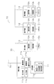
- the refrigeration apparatus management system 100 mainly includes an air conditioning apparatus 10, a controller 20, and a remote management apparatus 30.
- One air conditioner 10 includes one outdoor unit 11 and a plurality of indoor units 12.
- a plurality of air conditioners 10 are installed in one property 90.
- the controller 20 has a function of monitoring and controlling the air conditioning apparatus 10.
- the controller 20 is installed in a manager room of the property 90 or the like.
- a plurality of air conditioners 10 are connected to the controller 20.
- the controller 20 and the air conditioner 10 are connected by a dedicated line 70.
- the controller 20 controls the plurality of outdoor units 11 and the plurality of indoor units 12 connected to each outdoor unit 11.
- the remote management device 30 is a server provided in the remote management center 13 located remotely from the property 90.
- the remote management device 30 can be connected to the controller 20 via the Internet 60.
- the refrigerant leakage detection operation mode is an operation mode for detecting the presence or absence of refrigerant leakage.
- all the indoor units 12 connected to the target outdoor unit 11 are forcibly operated in the cooling mode for a predetermined time (for example, 110 minutes).
- the cooling circuit is forcibly operated for a predetermined time, so that the inside of the refrigerant circuit is set as described in JP 2007-163099 A, WO 2007/069578 A, EP 1970652 A1 and the like.
- the state of the circulating refrigerant is stabilized, and the refrigerant amount in the refrigerant circuit is calculated.
- each configuration included in the refrigeration apparatus management system 100 will be described.
- the air conditioner 10 includes a single outdoor unit 11 and a plurality of indoor units 12.
- a maximum of 64 indoor units 12 can be connected to one outdoor unit 11. That is, one refrigerant circuit is composed of one outdoor unit 11 and a maximum of 64 indoor units 12.
- the air conditioner 10 constitutes a refrigerant circuit as a whole, which includes a compressor, a heat exchanger, and the like (not shown).
- the R32 simple refrigerant flows through the refrigerant circuit.
- the outdoor unit 11 and the indoor unit 12 are connected by a dedicated line 70 and a refrigerant pipe.
- the air conditioner 10 is separately attached with a remote controller 12 c that receives an operation input to each indoor unit 12.
- the remote control 12c has an input unit and a display unit.
- the input unit receives a control command for each indoor unit 12.
- the display unit displays the operation status of each indoor unit 12.
- the operation status displayed on the display unit of the remote controller 12c includes information indicating that any one of the cooling operation / heating operation / inspection / refrigerant leakage detection operation is being performed, the set temperature, the air volume, and the wind direction. Etc. are included. That is, the remote controller 12 c also functions as a display unit of the air conditioner 10 that displays various information about the air conditioner 10.
- the input unit disables input related to a predetermined operation after receiving a restriction command described later from the controller 20 until receiving a release command.
- the predetermined operation includes a power-off operation, an operation stop operation, an operation mode change operation, and the like.
- the indoor unit 12 mainly includes a communication unit 12a and a control unit 12b.
- the communication unit 12 a is an interface for performing communication with the outdoor unit 11.
- the control unit 12b receives a control signal from the outdoor unit 11 via the communication unit 12a, and operates each unit configuring the indoor unit 12 based on the control signal. In addition, the control unit 12b sends data related to the operation state (ON / OFF state, suction temperature, etc.) to the outdoor unit 11 via the communication unit 12a.
- Outdoor Unit The outdoor unit 11 mainly includes a communication unit 11a, an output unit 11b, an input unit 11c, and a control unit (operation input unit) 11e.
- the communication unit 11a is an interface for performing communication with the indoor unit 12 as described above.
- the communication unit 11 a is also an interface for performing communication with the controller 20.
- the output unit 11b is a plurality of LEDs that are turned on or off.
- the LED is provided on a printed board (not shown).
- the output part 11b shows the state of the air conditioning apparatus 10 by turning on or off the plurality of LEDs.
- the state of the air conditioner 10 indicated by the output unit 11b includes the presence / absence of an abnormality in the outdoor unit 11, the type of abnormality that has occurred, and the presence / absence of refrigerant leakage.
- the output unit 11 b changes the lighting / extinguishing mode of the LED according to the state of the air conditioning apparatus 10.
- the input unit 11c is a button that receives a command to execute the refrigerant leakage detection operation from a maintenance worker.
- the input unit 11c is a button for direct operation when a maintenance worker visits the site where the air conditioner 10 is installed.
- the button is provided on the casing of the outdoor unit 11 (not shown).
- the storage unit 11d is mainly composed of a ROM, a RAM, and a hard disk.
- the storage unit 11d stores a program that can be read and executed by the control unit 11e described later.
- operation data, initial amount data, and current amount data are stored in the storage unit 11d.
- the operation data includes the operation data of the outdoor unit 11 and the operation data of the indoor unit 12.
- the operation data of the outdoor unit 11 means state values of various components included in the outdoor unit 11 and the outdoor temperature and humidity detected by the outdoor unit 11.
- the state values of various components included in the outdoor unit 11 are, for example, the frequency of the compressor, the rotational speed of the outdoor fan, and the temperature and pressure of the refrigerant at predetermined positions in the refrigerant circuit.
- the operation data of the indoor unit 12 includes operation parameters of the indoor unit 12, indoor temperature, indoor humidity, and state values of various components included in the indoor unit 12.
- the operation parameters of the indoor unit 12 are, for example, the operation mode such as the start / stop state of the indoor unit 12, the set temperature, the set humidity, the set air volume, the set air direction, and the cooling / heating / fan / dehumidification.
- the state values of various components included in the indoor unit 12 are, for example, the rotational speed of the indoor fan, the temperature and pressure of the refrigerant at a predetermined position of the refrigerant circuit.
- the operation data includes data that can identify whether the air conditioner 10 is operating, inspecting, or in an emergency stop, and data that can identify whether the air conditioner 10 is normal or abnormal. It is.
- the initial amount data is data related to the amount of refrigerant charged by the automatic refrigerant charging operation performed at the beginning of installation of the air conditioner 10, and depends on the configuration of the air conditioner 10 at the initial installation of the air conditioner 10. This is data relating to the amount of refrigerant charged in the refrigerant circuit.
- the initial amount data is a reference refrigerant amount (reference refrigerant amount).
- the initial amount data is stored in the storage unit 11d as initial amount data together with the execution date and time when the first refrigerant automatic charging operation is performed.
- the current amount data is data relating to the amount of refrigerant currently filled in the refrigerant circuit.
- the current amount data is data obtained by performing the coolant leakage detection operation.
- the current amount data is the latest data related to the amount of refrigerant obtained by performing the latest refrigerant leakage detection operation.
- the current amount data is stored in the storage unit 11d together with the date and time of the refrigerant leakage detection operation after the refrigerant leakage detection operation is performed.
- the storage unit 11d may include information related to an error that has occurred during the execution of the coolant leakage detection operation.
- the control unit 11e is mainly composed of a CPU.
- the control unit 11e reads out and executes the program stored in the storage unit 11d.
- the control unit 11e functions as an operation input unit.
- the operation input unit receives various control commands sent from the controller 20.
- the control part 11e operates the air conditioning apparatus 10 (namely, the outdoor unit 11 and the indoor unit 12) based on the control command received by the operation input part.
- the operation input unit disables input related to a predetermined operation until a cancel command is received after receiving a later-described restriction command from the controller 20.
- the predetermined operation is a power OFF operation, an operation stop operation, an operation mode change operation, or the like, as described above.
- the control unit 11e operates each unit constituting the outdoor unit 11 in accordance with a control command (start / stop of the indoor unit 12, set temperature, set humidity, set air volume, or set air direction, operation mode) sent from the controller 20. Let Specifically, the control unit 11e generates a control command for adjusting the frequency of the compressor, the rotational speed of the fan, and the opening degrees of various valves. Further, the control unit 11 e acquires operation data from the indoor unit 12 in response to a control command sent from the controller 20, and transmits the acquired operation data of the indoor unit 12 to the controller 20.
- a control command start / stop of the indoor unit 12, set temperature, set humidity, set air volume, or set air direction, operation mode
- control unit 11 e acquires operation data for the outdoor unit 11 from the storage unit 11 d in response to a control command sent from the controller 20, and transmits the acquired operation data for the outdoor unit 11 to the controller 20. Furthermore, the control part 11e performs a refrigerant
- the control part 11e memorize
- the controller 20 has a function of monitoring and controlling the air conditioning apparatus 10.
- the controller 20 mainly includes a communication unit 21, a display unit 22, an input unit (refrigerant leakage detection schedule setting unit, normal schedule setting unit) 23, a storage unit 24, and a control unit 25.
- the communication unit 21 is an interface that enables the controller 20 to be connected to the Internet 60 and the air conditioning apparatus 10.
- the display unit 22 is mainly composed of a display.
- the input unit 23 receives various settings for the controller 20.
- the input unit 23 includes a touch panel that covers the display.
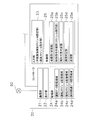
- the display unit 22 includes a management screen 221 (see FIG. 4) of the air conditioner 10 mainly used by the user, screens 222 and 223 (see FIGS. 5 and 6) relating to the coolant leakage detection operation mainly used by maintenance workers, And the detection result (refer FIG. 7) of refrigerant
- operation is displayed.
- the management screen 221 displays operation information for each indoor unit 12.
- the operation information displayed on the management screen 221 includes, for example, states such as stop / operation / abnormality / communication abnormality.
- the driving information is stored in the storage unit 24 described later.
- the management screen 221 is provided with various buttons B1 to B7 for controlling each indoor unit 12.
- the button B1 is a button (collective operation button) for operating all the indoor units 12 at once.
- the button B2 is a button (batch stop button) for stopping all the indoor units 12 at once.
- the button B3 is a button (operation button) for operating the indoor unit 12 individually.
- the button B4 is a button (stop button) for individually stopping the indoor unit 12.
- the button B5 is a button (detail button) for setting details (operation mode, temperature, humidity, air volume, wind direction, etc.) of the operation of each indoor unit 12.
- the operation mode includes a cooling operation mode, a heating operation mode, and a dehumidifying operation mode.
- the button B6 is a button (operation schedule setting button) for setting an operation schedule (normal schedule) in the indoor unit 12.
- the operation schedule is a schedule related to the time when the operation of the indoor unit 12 is started, the time when the operation is stopped, and the operation content.
- the management screen 221 shifts to an operation schedule setting screen (not shown).
- operation start time, operation stop time, operation content operation mode, temperature, humidity, air volume, wind direction, etc. can be set.
- Button B7 is a button used by a maintenance worker. When the button B7 is touched, a screen (not shown) for inputting a predetermined ID or the like is displayed. When a predetermined ID is entered on the screen, an operation screen for maintenance workers (see FIGS. 5 and 6) is displayed.
- the operation screen for the maintenance worker includes a screen related to the coolant leakage detection operation.
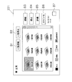
- the screen related to the refrigerant leak detection operation includes a screen (detection operation start screen) 222 for starting the refrigerant leak detection operation as shown in FIG. 5 and a schedule (detection of the refrigerant leak detection operation as shown in FIG. 6).
- a screen (detection schedule setting screen) 223 for receiving an input of setting of (schedule) is included.
- the detection schedule is a schedule related to the date and time when the refrigerant leakage detection operation mode is executed.
- the detection operation start screen 222 is provided with a region R1 indicating registered contents and buttons B11 to B16.
- the filling status and the detection schedule (start date and time) are shown.
- region R1 is the date and time which visits earliest among the detection schedules set.
- the button B11 is a button (registration button) used for newly registering the schedule of the refrigerant leakage detection operation.
- the button B12 is a button (detection start button) for starting the refrigerant leak detection operation.
- the button B13 is a button (detection stop button) for stopping the refrigerant leak detection operation.
- the button B14 is a button (detection schedule setting button) for setting a schedule for the refrigerant leakage detection operation.
- the detection schedule setting button B14 is touched, the detection operation start screen 222 is switched to the detection schedule setting screen 223 (see FIG. 6).
- the detection schedule setting screen 223 has a configuration in which four schedules for each outdoor unit 11 can be set. In other words, the detection schedule setting screen 223 can input four start dates and times of the refrigerant leakage detection operation for the refrigerant circuit including each outdoor unit 11.
- the detection schedule setting screen 223 is switched to the detection operation start screen 222.
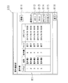
- the button B15 is a button (detection result output button) for outputting the detection result obtained by the refrigerant leak detection operation in the CSV format.
- the detection result output button B15 is output, as shown in FIG. 7, information on the execution date and time of the refrigerant leak detection operation and the refrigerant leak amount is output in CSV format for all registered outdoor units 11.
- the detection result information about the refrigerant leakage detection operation for the past 100 times is shown for each outdoor unit 11. Further, the latest data is shown at the top of the CSV data indicating the detection result (at the top of the data).
- the button B16 is a button (end button) for ending the setting related to the refrigerant leakage detection operation. By touching the end button B ⁇ b> 16, the detection operation start screen 222 is switched to the management screen 221.
- the various buttons B1 to B7 on the management screen 221 are invalidated when a leak detection operation described later is started.
- Various settings input by the input unit 23 are stored in the storage unit 24 described later.
- the storage unit 24 mainly includes a ROM, a RAM, and a hard disk.
- the storage unit 24 stores a program that can be read and executed by the control unit 25 described later.
- the storage unit 24 mainly includes an operation data storage area 24a, an operation schedule storage area 24b, a detection schedule storage area 24c, and a detection related data storage area 24d.
- (3-3-1) Operation Data Storage Area The operation data storage area 24a stores operation data of the air conditioner 10 acquired by the acquisition unit 25a described later.
- the operation data includes the operation data of the outdoor unit 11 and the operation data of the indoor unit 12.
- the operation data of the outdoor unit 11 includes state values of various components included in the outdoor unit 11 and the outside air temperature and outside air humidity detected by the outdoor unit 11, and the operation data of the indoor unit 12 includes The operation parameters of the indoor unit 12, the indoor temperature, the indoor humidity, and the state values of various components included in the indoor unit 12 are included.
- the operation schedule storage area 24b stores an operation schedule input via the input unit 23 or an operation schedule sent from the remote management device 30.
- the operation schedule is a schedule related to the time when the operation of the indoor unit 12 is started, the time when the operation is stopped, and the operation content.
- the operation schedule stored in the operation schedule storage area 24b is overwritten by a new operation schedule when a new operation schedule is set.
- (3-3-3) Detection Schedule Storage Area The detection schedule storage area 24c stores a detection schedule input via the input unit 23 or a detection schedule sent from the remote management device 30. As described above, the detection schedule is a schedule related to the date and time when the refrigerant leakage detection operation mode is performed.
- the detection schedule stored in the detection schedule storage area 24c is also overwritten by the new detection schedule by setting a new detection schedule.
- the detection related data storage area 24d stores initial amount data and current amount data acquired by the acquisition unit 25a described later.
- the initial amount data is data relating to the amount of refrigerant obtained by the automatic refrigerant charging operation performed at the beginning of the installation of the air conditioner 10.
- the current amount data is also data related to the amount of refrigerant obtained by the refrigerant leak detection operation as described above, and is data related to the amount of refrigerant currently charged in the refrigerant circuit.
- the detection related data storage area 24d also stores a determination history of the detection availability condition determined by the detection availability determination unit 25c described later.
- the determination history includes information regarding an error that occurred before the refrigerant leak detection operation was executed.
- the detection related data storage area 24d may include information related to an error that occurred during the execution of the coolant leakage detection operation. Information on the error is included in information acquired by the acquisition unit 25a at a predetermined time interval (one minute interval in the present embodiment).
- the detection-related data storage area 24d stores a result (detection result) determined by a leakage determination unit 25d described later in association with the date and time when the refrigerant leakage detection operation is performed (see FIG. 7).
- the control unit 25 is mainly composed of a CPU, and mainly reads out and executes a program stored in the storage unit 24, thereby mainly obtaining an acquisition unit (reception unit) 25a and a control command generation.
- the acquisition unit 25a collects operation data of each air conditioner 10 at a predetermined time interval (1 minute interval in the present embodiment).
- the acquisition unit 25 a acquires the operation data of the outdoor unit 11 from the control unit 11 e of each outdoor unit 11. In addition, the acquisition unit 25 a collects operation data of the indoor unit 12 via the outdoor unit 11. The operation data collected by the acquisition unit 25a is stored in the operation data storage area 24a.
- the acquisition part 25a will acquire initial amount data from the air conditioning apparatus 10 after that. .
- the acquisition unit 25a requests the outdoor unit 11 for initial amount data stored in the storage unit 11d.
- the initial amount data acquired by the acquisition unit 25a is stored in the detection related data storage area 24d.
- the acquisition unit 25a acquires the current amount data from the air conditioner 10 over a predetermined time (110 minutes in the present embodiment) after the detection control command is transmitted to the air conditioner 10.
- control unit 11e of the outdoor unit 11 calculates the refrigerant amount in the refrigerant circuit over 110 minutes, and the acquisition unit 25a acquires the calculation result (current amount data).
- the current amount data acquired by the acquisition unit 25a is stored in the detection related data storage area 24d.
- the control command generation unit 25b generates various control commands to be executed by the air conditioner 10 based on the settings received by the input unit 23 and the settings received by the remote management device 30.
- the settings received by the input unit 23 and the settings received by the remote management device 30 include an immediate schedule, an operation schedule, and a detection schedule.
- the immediate schedule is a setting that allows the user to operate immediately under conditions desired by the user.
- the control command generation unit 25b generates the control command based on the detection schedule with priority over the operation schedule. In other words, when the detection schedule to be executed is stored, the control command generator 25b generates the control command (detection control command) for causing the air conditioner 10 to perform the refrigerant leakage detection operation with priority.
- the detection control command is a command for forcibly operating all the indoor units 12 included in the air conditioner 10 by cooling and collecting current amount data.
- control command generation unit 25b when the control command generation unit 25b generates a control command based on the detection schedule and the air conditioner 10 performs control based on the operation schedule, the control command generation unit 25b interrupts (or cancels) the control based on the operation schedule. ) To generate a control command (interrupt command), and transfers the interrupt command to the transmission unit 25e. Furthermore, after generating the interruption command, the control command generation unit 25b generates a control command (resumption command) for resuming the control based on the interrupted operation schedule when the refrigerant leakage detection operation ends and the detection result is obtained. Then, the restart command is delivered to the transmitter 25e.
- the control command generation unit 25b passes the detection control command to the transmission unit 25e after determining that the refrigerant leakage detection operation is possible by the detection possibility determination unit 25c described later.
- the detection control command is transmitted to the air conditioning apparatus 10 by a transmission unit 25e described later.
- the detection possibility determination unit 25c determines that the refrigerant leakage detection operation is impossible, the detection control command is not delivered to the transmission unit 25e.
- control command generation unit 25b delivers the detection control command to the transmission unit 25e
- the control unit 20b displays the display unit (the display unit of the remote controller 12c, the display unit 22 of the controller 20, and the display unit of the remote monitoring device 30).
- a command (display command) for causing all or any of 32 to perform specific display is generated, and the display command is also transferred to the transmission unit 25e.
- the specific display is a display accompanying the refrigerant leak detection operation, and is a display indicating that the air conditioner 10 is performing the refrigerant leak detection operation.
- the air conditioner 10 when the detection control command is transmitted to the air conditioner 10 by the transmission unit 25e, the air conditioner 10 performs a refrigerant leak detection operation and displays an indication that the refrigerant leak detection operation is being performed. Shown on the display. Further, when the control command generation unit 25b delivers the detection control command to the transmission unit 25e, the control command generation unit 25b further generates a regulation command, and also delivers the regulation command to the transmission unit 25e.
- the restriction command is a command for restricting the operation input unit of the air conditioner 10 from accepting an input of a predetermined operation.
- the predetermined operation is a power-off operation, an operation stop operation, an operation mode change operation, or the like. At this time, it is preferable that the input unit of the remote controller 12c and the input unit 23 of the controller 20 be regulated not to accept input.
- the control command generation unit 25b includes a command for terminating the specific display (display end command) and a command for canceling the operation input restriction ( Release command).
- the display end command and the release command are also passed to the transmission unit 25e.
- the detection determination unit 25c is a target air conditioner based on a predetermined detection permission condition. 10 whether or not the refrigerant leakage detection operation is possible.
- the detection possibility determination unit 25c confirms that the air conditioner 10 that is the target of the refrigerant leakage detection operation is not in a state (unsuitable state) in which the refrigerant leakage detection operation is impossible.
- the predetermined detection availability condition is a condition relating to a communication state with the air conditioner 10 and an operation state of the air conditioner 10. Specifically, the predetermined detection availability condition is a condition regarding the presence / absence of communication abnormality, the refrigerant charging state, and the operating state of the air-conditioning apparatus 10 (during inspection, emergency stop, abnormality).
- the detectability determination unit 25c determines whether there is a communication abnormality between the controller 20 and the outdoor unit 11. Specifically, the detection possibility determination unit 25c communicates with the outdoor unit 11 a predetermined number of times (in this embodiment, four times), and if the communication is not established within the predetermined number of times, the leak detection operation is impossible. Judge. When the communication is established, thereafter, the detection possibility determination unit 25c determines the refrigerant filling state in the refrigerant circuit based on the initial amount data stored in the detection related data storage area 24d. Specifically, the detection possibility determination unit 25c determines whether or not the refrigerant charging amount of the air conditioning apparatus 10 that is the target of the refrigerant leakage detection operation is other than “0”. When the value indicated by the initial amount data (the amount of refrigerant initially charged in the refrigerant circuit) is “0”, it is determined that the refrigerant leakage detection operation is impossible.
- the detectability determination unit 25c determines whether or not the air conditioner 10 is operating normally based on the operation data stored in the operation data storage area 24a. Specifically, the detectability determination unit 25c determines whether the air conditioner 10 is being inspected, whether it is in an emergency stop, or whether an abnormality has occurred. More specifically, the detectability determination unit 25c determines whether the outdoor unit 11 and the indoor unit 12 that constitutes the same refrigerant system as the outdoor unit 11 are under inspection, whether they are in an emergency stop, or not. It is determined whether or not it has occurred.
- the detectability determination unit 25c detects refrigerant leakage. It is determined that the detection operation is impossible.
- the detection availability determination unit 25c stores a detection history of detection availability conditions in the detection related data storage area 24d.
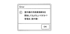
- the detection possibility determination unit 25c executes the refrigerant leakage detection operation before determining whether the refrigerant leakage detection operation is possible.
- a dialog for prompting confirmation is displayed on the display unit 22 (see FIG. 8).
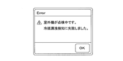
- the detectability determination unit 25c displays a dialog indicating the reason on the display unit 22 (see FIG. 9).
- the leakage determination unit 25d determines refrigerant leakage based on the detection related data stored in the detection related data storage area 24d.
- the result determined by the leakage determination unit 25d is stored in the detection related data storage area 24d in association with the date and time when the refrigerant leakage detection operation is executed (see FIG. 7).
- (3-5-5) Transmitter The transmitter 25e transmits various commands set by the controller 20 and various commands transmitted from the remote monitoring device 30 to the air conditioner 10. In other words, the transmission unit 25e transmits the control command generated by the control command generation unit 25b and the control command sent from the remote management device 30 to the air conditioner 10. In addition, the transmission unit 25e transmits the operation data stored in the operation data storage area 24a to the remote management device 30 at a predetermined time interval (in this embodiment, every 30 minutes). (4) Remote Management Device As shown in FIG.
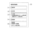
- the remote management device 30 mainly includes a communication unit 31, a display unit 32, an input unit (refrigerant leakage detection schedule setting unit, normal schedule setting unit) 33, a storage unit 34, And a server computer composed of a control unit (reception unit, transmission unit, schedule execution unit) 35.
- the remote management device 30 has a function of monitoring and controlling the air conditioning device 10 via the controller 20.
- the remote management device 30 according to the present embodiment causes the air conditioner 10 to execute the refrigerant leak detection operation via the controller 20.
- the communication unit 31 is a network interface that enables the remote management device 30 to be connected to the Internet 60.
- (4-2) Display Unit The display unit 32 mainly includes a display.
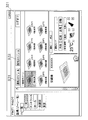
- the display unit 32 displays a management screen 321 of the air conditioner 10 as shown in FIG.
- the management screen 321 shows operation data of the air conditioner 10.
- the management screen 321 is provided with a plurality of buttons B31 and B32, and by clicking the buttons B31 and B32, more detailed settings for the control of the air conditioner 10 are performed. be able to.
- the button B31 is a button for setting an operation schedule (operation schedule setting button).
- the button B32 is a button for setting a detection schedule.
- the management screen 321 is switched to a screen related to the refrigerant leakage detection operation.
- the screen relating to the coolant leakage detection operation is a screen similar to the screen displayed on the display unit 22 of the controller 20.
- the screen related to the refrigerant leakage detection operation includes a screen (detection operation start screen) 222 for starting the refrigerant leakage detection operation as shown in FIG. 5 and a refrigerant leakage detection operation as shown in FIG.
- a screen (detection schedule setting screen) 223 for setting a schedule (detection schedule) is included.
- the input unit 33 mainly includes a mouse and a keyboard.
- (4-4) Storage Unit The storage unit 34 mainly includes a ROM, a RAM, and a hard disk.
- the storage unit 34 stores a program that can be read and executed by the control unit 25 described later.
- storage part 34 memorize
- the storage unit 34 also stores various settings (immediate schedule, operation schedule setting, and detection schedule setting) input via the input unit 33.
- various information operation data, various settings, etc. of the air conditioning apparatus 10
- corresponding information among the information stored in the storage unit 34 is based on the information. Overwritten.
- the control unit 35 is mainly composed of a CPU.
- the control unit 35 reads and executes the program stored in the storage unit 34.
- the control unit 35 generates a control command based on the settings (immediate schedule, operation schedule setting, and detection schedule setting) input by the input unit 33.
- the control unit 35 transmits the control command to the controller 20 via the Internet 60. Further, the control unit 35 acquires various types of information (operation data, various settings, etc.) from the controller 20 and stores the acquired information in the storage unit 34.
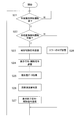
- FIG. 12 to FIG. 14 a process flow in the controller 20 related to the refrigerant leak detection operation will be described.
- FIG. 12 shows the flow of processing related to the refrigerant leakage detection operation based on the immediate schedule
- FIG. 13 shows the flow of processing related to the refrigerant leakage detection operation based on the detection schedule
- FIG. 14 shows a flow of processing for prioritizing the detection schedule over the driving schedule.
- step S10 it is determined whether or not there has been a request for refrigerant leakage detection operation.
- step S10 it waits until there exists a request
- step S11 a dialog prompting confirmation of execution of the refrigerant leakage detection operation is displayed (see FIG. 8).
- the dialog is displayed in an apparatus in which an immediate schedule for refrigerant leakage detection operation is set. That is, if the immediate schedule is set by the controller 20, the dialog is displayed on the display unit 22 of the controller 20. If the immediate schedule is set by the remote management device 30, the dialog is It is assumed to be displayed on the display unit 32 of the device 30. Thereafter, the process proceeds to step S12.
- step S12 it is determined whether the refrigerant leak detection operation is possible. Whether or not the refrigerant leakage detection operation is possible is determined based on the detection possibility condition. Specifically, whether there is a communication abnormality between the air conditioner 10 (outdoor unit 11) and the control 20 that is the target of the refrigerant leak detection operation, whether the refrigerant is filled in the refrigerant circuit of the target air conditioner 10, It is determined whether or not the air conditioner 10 is being inspected, whether or not the target air conditioner 10 is in an emergency stop, and whether or not an abnormality has occurred in the target air conditioner 10. If it is determined in step S12 that the refrigerant leakage detection operation is possible, the process proceeds to step S13.
- step S ⁇ b> 13 a command (detection control command) for performing the refrigerant leak detection operation is transmitted to the air conditioner 10.
- the air conditioning apparatus 10 that has received the detection control command switches to the refrigerant leakage detection operation mode, forcibly performs the cooling operation, and starts collecting the current amount data.
- the process proceeds to step S14.
- step S ⁇ b> 14 a display command and a regulation command are sent to the air conditioner 10.
- the display command is a command for causing the air conditioner 10 to perform specific display.
- the specific display is a display accompanying the refrigerant leak detection operation, and is a display indicating that the air-conditioning apparatus 10 is performing the refrigerant leak detection operation.
- the restriction command is also a command for restricting the air conditioner 10 from accepting an input of a predetermined operation as described above. As a result, the air conditioner 10 indicates that the refrigerant leakage detection operation is being performed, and the input of a predetermined operation from the outside is not accepted. Thereafter, the process proceeds to step S15.
- step S15 the current amount data is acquired from the air conditioner 10 that is performing the refrigerant leakage detection operation. Specifically, data related to the amount of refrigerant (current amount data) included in the refrigerant circuit of the current air conditioner 10 is acquired from the control unit 11 e of the outdoor unit 11. The current amount data collected by the acquisition unit 25a is stored in the detection related data storage area 24d. Thereafter, the process proceeds to step S16.
- the determination result (detection result) in step S16 is stored in the detection related data storage area 24d in association with the date and time when the refrigerant leakage detection operation is executed (see FIG. 7).
- step S17 In step S ⁇ b> 17, the detection result is displayed on the display units 22 and 32.
- a detection result shall be displayed in the apparatus which had the request
- step S18 a display end command and a release command are transmitted to the air conditioner 10.
- the display end command is a command for ending the specific display
- the cancel command is a command for canceling the input restriction.
- the process proceeds to step S19.
- step S19 a log for items determined to be impossible (error) is stored in the detection-related data storage area. Thereafter, the process proceeds to step S20.
- step S20 an error dialog as shown in FIG.
- the error dialog is assumed to be displayed in the apparatus in which the immediate schedule of the refrigerant leakage detection operation is set. That is, if the immediate schedule is set by the controller 20, the error dialog is displayed on the display unit 22 of the controller 20, and if the immediate schedule is set by the remote management device 30, the error dialog is It is displayed on the display unit 32 of the remote management device 30.
- step S21 it is determined whether or not refrigerant leakage detection driving is necessary based on the detection schedule.
- step S21 it waits until the refrigerant
- step S22 it is determined whether the refrigerant leak detection operation is possible.
- Whether or not the refrigerant leakage detection operation is possible is determined based on the detection possibility condition. Specifically, whether there is a communication abnormality between the air conditioner 10 (outdoor unit 11) and the control 20 that is the target of the refrigerant leak detection operation, whether the refrigerant is filled in the refrigerant circuit of the target air conditioner 10, It is determined whether or not the air conditioner 10 is being inspected, whether or not the target air conditioner 10 is in an emergency stop, and whether or not an abnormality has occurred in the target air conditioner 10. If it is determined in step S22 that the refrigerant leak detection operation is possible, the process proceeds to step S23.
- step S ⁇ b> 23 a command (detection control command) for performing the refrigerant leak detection operation is transmitted to the air conditioner 10.
- the air conditioning apparatus 10 that has received the detection control command switches to the refrigerant leakage detection operation mode, and all the indoor units 12 forcibly perform the cooling operation and start collecting the current amount data.
- step S24 a display command and a regulation command are sent to the air conditioning apparatus 10. As a result, the air conditioner 10 indicates that the refrigerant leakage detection operation is being performed, and the input of a predetermined operation from the outside is not accepted.
- step S25 the process proceeds to step S25.
- step S25 the current amount data is acquired from the air conditioner 10 that is performing the refrigerant leakage detection operation. Specifically, data related to the amount of refrigerant (current amount data) included in the refrigerant circuit of the current air conditioner 10 is acquired from the control unit 11 e of the outdoor unit 11. The current amount data collected by the acquisition unit 25a is stored in the detection related data storage area 24d. Thereafter, the process proceeds to step S26.
- the determination result (detection result) in step S26 is stored in the detection-related data storage area 24d in association with the date and time when the refrigerant leakage detection operation is executed (see FIG. 7).
- the detection result stored in the detection-related data storage area is output in the CSV format by receiving an input with the button B15 on the detection operation start screen 222.
- a display end command and a release command are transmitted to the air conditioning apparatus 10.
- the display end command is a command for ending the specific display
- the cancel command is a command for canceling the input restriction.
- step S28 a log of items determined to be impossible (error) is stored in the detection related data storage area.
- the log stored in the detection-related data storage area is output in the CSV format by receiving an input with the button B15 on the detection operation start screen 222.
- step S33 the running operation schedule is interrupted. In other words, the control content of the air conditioner 10 based on the operation schedule is canceled, and the air conditioner 10 is stopped. Thereafter, the process proceeds to step S34.
- step S34 a detection control command is transmitted. That is, the air conditioner 10 is caused to perform the refrigerant leak detection operation. Thereafter, the process proceeds to step S35.
- step S35 it is determined whether or not the refrigerant leakage detection operation is finished. In step S35, it waits until a refrigerant
- step S36 it is determined whether there is an interrupted operation schedule. If there is no interrupted operation schedule in step S36, the process returns to step S31. On the other hand, if there is an interrupted operation schedule in step S36, the process proceeds to step S37.
- step S37 the control of the air conditioner 10 based on the interrupted operation schedule is resumed. Then, it progresses to step S38 and will return to step S31, if an operation schedule is complete
- 6-1 the detection schedule related to the refrigerant leakage detection operation of the air conditioner 10 can be set by the controller 20 or the remote monitoring apparatus 30 located away from the air conditioner 10. .
- the air conditioner 10 performs the refrigerant leak detection operation based on the detection schedule. Accordingly, the maintenance worker can cause the air conditioner 10 to perform the refrigerant leakage detection operation without going to the site where the air conditioner 10 is installed. Therefore, even when the number of air conditioning apparatuses 10 to be subjected to the refrigerant leakage detection operation is increased, it is possible to reduce the burden and cost.
- a command (detection control command) for performing the refrigerant leak detection operation is transmitted to the air conditioner 10 and a display command is transmitted.
- the display command is a command for causing the display unit (not shown) of the air conditioner 10 to perform a specific display indicating that the refrigerant leakage detection operation is being performed. Thereby, it is possible to notify the user of the refrigeration apparatus that the refrigeration apparatus is in the refrigerant leak detection operation.
- a command (detection control command) for performing the refrigerant leak detection operation is transmitted to the air conditioner 10 and a restriction command is transmitted.
- the restriction command is a command for restricting the air conditioning apparatus 10 from accepting an input of a predetermined operation.
- the communication state with the air conditioner 10, the operation state of the air conditioner 10, and the like are determined before causing the air conditioner 10 to perform the refrigerant leak detection operation.
- the controller 20 determines whether or not the refrigerant leakage detection operation can be performed in the air conditioner 10 based on a predetermined detection availability condition. When an accurate detection result cannot be obtained, the controller 20 does not generate a command for performing the refrigerant leakage detection operation. As a result, the reliability of the detection result can be improved.
- the operation schedule is a schedule for starting and stopping the operation of the air conditioner 10.
- the detection schedule is executed with priority over the operation schedule.
- all the indoor units 12 are forcibly cooled, and data relating to the amount of refrigerant currently charged in the refrigerant circuit (current amount data) is collected. It is. If there is a refrigerant leak, it will cause a decrease in performance or failure of the air conditioner 10, so it is not preferable to leave the state in which the refrigerant leaks.
- the air conditioning apparatus 10 used in the present embodiment uses an R32 single refrigerant.
- R32 is a slightly flammable refrigerant. It is very important to prevent leakage of such a slightly flammable refrigerant. In addition, it may be obliged to regularly report the inspection result of the refrigerant leakage.
- the air conditioner 10 is controlled such that the refrigerant leakage detection operation based on the detection schedule is executed with priority over the operation based on the normal operation schedule. Thereby, it becomes possible to confirm the refrigerant
- one controller 20 installed in one property 90 is connected to the remote management apparatus 30, but connected to the remote management apparatus 30.
- the number of controllers 20 to be performed is not limited to this. That is, the remote management device 30 may be connected to a number of controllers 20 installed in a number of properties 90, respectively.
- a plurality of controllers 20 may be installed in one property 90, and the remote management device 30 may be connected to a plurality of controllers 20 arranged in one property 90.
- the controller 20 generates a control command based on the setting received by the remote management device 30.
- the function similar to the control unit 25 of the controller 20 may be provided in the remote management device 30.
- the refrigerant leak detection operation is executed at a place away from the place where the air conditioner 10 is installed, and further, the refrigerant leak detection operation is executed at a place away from the air conditioner 10. The result can be confirmed.
- (7-3) Modification C In the above embodiment, the transmission of the detection control command and the transmission of the display command and the regulation command are performed in different steps. However, all of the detection control command, the display command, and the regulation command may be transmitted almost simultaneously. .
- the display end command and the release command are transmitted to the air conditioner 10 in step S18.
- the command may be transmitted to the air conditioner 10.
- the result (detection result) of the refrigerant leakage detection operation obtained by the controller 20 can be confirmed by the remote management apparatus 30, but the detection result obtained by the controller 20 May be configured so that it can be confirmed by other portable terminals.
- the determination of the detection availability condition may be performed in any order. Moreover, when it is determined that the refrigerant leakage detection operation is impossible based on any one of the conditions, the other detection availability conditions may not be determined.
- a plurality of air conditioners 10 are controlled by a single controller 20 installed in a property 90.
- one controller 20 may be installed for one air conditioner 10, and the one air conditioner 10 may be controlled by the one controller 20.
- a remote controller having the same function as that of the controller 20 may be provided instead of the remote controller 12 c provided in each indoor unit 12.
- Air conditioning equipment (refrigeration equipment) 11 outdoor unit 11a communication unit 11b output unit 11c input unit 11d storage unit 11e control unit (operation input unit) 12 indoor unit 12a communication unit 12b control unit 12c remote control 20 controller 21 communication unit 22 display unit 23 input unit (refrigerant leakage detection schedule setting unit, normal schedule setting unit) 24 storage unit 24a operation data storage region 24b operation schedule storage region 24c detection schedule storage region 24d detection related data storage region 25 control unit 25a acquisition unit (reception unit) 25b Control command generation unit (schedule execution unit) 25c Detectability determination unit 25d Leakage determination unit 25e Transmission unit (transmission unit) 30 Remote management device 31 Communication unit 32 Display unit 33 Input unit (refrigerant leakage detection schedule setting unit, normal schedule setting unit) 34 storage unit 35 control unit (reception unit, transmission unit, schedule execution unit) 100 Refrigeration equipment management system
Landscapes
- Engineering & Computer Science (AREA)
- Mechanical Engineering (AREA)
- General Engineering & Computer Science (AREA)
- Chemical & Material Sciences (AREA)
- Combustion & Propulsion (AREA)
- Physics & Mathematics (AREA)
- Thermal Sciences (AREA)
- Air Conditioning Control Device (AREA)
Priority Applications (3)
| Application Number | Priority Date | Filing Date | Title |
|---|---|---|---|
| US14/405,135 US9791195B2 (en) | 2012-06-04 | 2013-05-15 | Cooling device management system with refrigerant leakage detection function |
| EP13800693.7A EP2857771B1 (fr) | 2012-06-04 | 2013-05-15 | Système de gestion de dispositif de réfrigération |
| CN201380029353.8A CN104364585B (zh) | 2012-06-04 | 2013-05-15 | 冷冻装置管理系统 |
Applications Claiming Priority (2)
| Application Number | Priority Date | Filing Date | Title |
|---|---|---|---|
| JP2012-127270 | 2012-06-04 | ||
| JP2012127270A JP2013250038A (ja) | 2012-06-04 | 2012-06-04 | 冷凍装置管理システム |
Publications (1)
| Publication Number | Publication Date |
|---|---|
| WO2013183414A1 true WO2013183414A1 (fr) | 2013-12-12 |
Family
ID=49711814
Family Applications (1)
| Application Number | Title | Priority Date | Filing Date |
|---|---|---|---|
| PCT/JP2013/063545 Ceased WO2013183414A1 (fr) | 2012-06-04 | 2013-05-15 | Système de gestion de dispositif de réfrigération |
Country Status (5)
| Country | Link |
|---|---|
| US (1) | US9791195B2 (fr) |
| EP (1) | EP2857771B1 (fr) |
| JP (1) | JP2013250038A (fr) |
| CN (1) | CN104364585B (fr) |
| WO (1) | WO2013183414A1 (fr) |
Cited By (8)
| Publication number | Priority date | Publication date | Assignee | Title |
|---|---|---|---|---|
| CN104482631A (zh) * | 2014-12-18 | 2015-04-01 | 珠海格力电器股份有限公司 | 一种空调缺氟保护方法、装置及空调器 |
| WO2017094059A1 (fr) * | 2015-11-30 | 2017-06-08 | 三菱電機株式会社 | Dispositif de gestion de quantité de fluide frigorigène et système de gestion de quantité de fluide frigorigène |
| EP3147595A4 (fr) * | 2015-04-03 | 2017-09-06 | Mitsubishi Electric Corporation | Dispositif à cycle de réfrigération et système à cycle de réfrigération |
| US11131471B1 (en) * | 2020-06-08 | 2021-09-28 | Emerson Climate Technologies, Inc. | Refrigeration leak detection |
| US11359846B2 (en) | 2020-07-06 | 2022-06-14 | Emerson Climate Technologies, Inc. | Refrigeration system leak detection |
| US11885516B2 (en) | 2020-08-07 | 2024-01-30 | Copeland Lp | Refrigeration leak detection |
| WO2024071435A1 (fr) * | 2022-09-30 | 2024-04-04 | ダイキン工業株式会社 | Dispositif de gestion pour dispositif à cycle de réfrigération |
| JP2024052431A (ja) * | 2022-09-30 | 2024-04-11 | ダイキン工業株式会社 | 冷媒漏洩点検システム及び冷媒漏洩点検方法 |
Families Citing this family (27)
| Publication number | Priority date | Publication date | Assignee | Title |
|---|---|---|---|---|
| US10119738B2 (en) | 2014-09-26 | 2018-11-06 | Waterfurnace International Inc. | Air conditioning system with vapor injection compressor |
| WO2016157498A1 (fr) * | 2015-04-02 | 2016-10-06 | 三菱電機株式会社 | Dispositif de climatisation |
| JP6640473B2 (ja) * | 2015-05-28 | 2020-02-05 | 日立ジョンソンコントロールズ空調株式会社 | 空気調和機、及び空気調和機の表示制御方法 |
| WO2017002213A1 (fr) * | 2015-06-30 | 2017-01-05 | 三菱電機株式会社 | Dispositif de détection de fuite de fluide frigorigène |
| WO2017006462A1 (fr) * | 2015-07-08 | 2017-01-12 | 三菱電機株式会社 | Appareil de conditionnement d'air |
| WO2017199342A1 (fr) * | 2016-05-17 | 2017-11-23 | 三菱電機株式会社 | Dispositif à cycle frigorifique |
| US10871314B2 (en) | 2016-07-08 | 2020-12-22 | Climate Master, Inc. | Heat pump and water heater |
| US10866002B2 (en) | 2016-11-09 | 2020-12-15 | Climate Master, Inc. | Hybrid heat pump with improved dehumidification |
| JP6875423B2 (ja) * | 2017-01-19 | 2021-05-26 | 三菱電機株式会社 | 冷凍サイクル装置 |
| CN110291338B (zh) * | 2017-01-20 | 2022-01-18 | 三菱电机株式会社 | 空气调节装置 |
| ES2968240T3 (es) * | 2017-05-24 | 2024-05-08 | Mitsubishi Electric Corp | Sistema de acondicionamiento de aire |
| CN110375468B (zh) | 2018-04-13 | 2022-10-11 | 开利公司 | 风冷热泵系统、用于其的制冷剂泄漏检测方法及检测系统 |
| US11592215B2 (en) | 2018-08-29 | 2023-02-28 | Waterfurnace International, Inc. | Integrated demand water heating using a capacity modulated heat pump with desuperheater |
| US11686491B2 (en) * | 2019-02-20 | 2023-06-27 | Johnson Controls Tyco IP Holdings LLP | Systems for refrigerant leak detection and management |
| JP7295386B2 (ja) * | 2019-02-27 | 2023-06-21 | ダイキン工業株式会社 | 検査実行方法、管理サーバ |
| CA3081986A1 (fr) | 2019-07-15 | 2021-01-15 | Climate Master, Inc. | Systeme de conditionnement d`air a regulation de puissance et production d`eau chaude controlee |
| US11231198B2 (en) | 2019-09-05 | 2022-01-25 | Trane International Inc. | Systems and methods for refrigerant leak detection in a climate control system |
| DE102020104956B3 (de) * | 2020-02-26 | 2021-05-06 | Bender Gmbh & Co. Kg | Überwachungsvorrichtung und Verfahren sowie eine erweiterte Überwachungsvorrichtung und erweitertes Verfahren zur Isolationsüberwachung eines ungeerdeten elektrischen Systems mit geerdet betriebener Flüssigkeitskühlung |
| JP6927397B1 (ja) * | 2020-09-24 | 2021-08-25 | ダイキン工業株式会社 | 空気調和システムおよびその室内機 |
| JP7137087B2 (ja) * | 2020-12-01 | 2022-09-14 | ダイキン工業株式会社 | 空調機制御システム、サーバ装置及び空調機制御方法 |
| JP2022122323A (ja) * | 2021-02-10 | 2022-08-23 | パナソニックIpマネジメント株式会社 | 空気調和機 |
| JP7269508B2 (ja) * | 2021-07-09 | 2023-05-09 | ダイキン工業株式会社 | サーバ、システム、および方法 |
| US12181189B2 (en) | 2021-11-10 | 2024-12-31 | Climate Master, Inc. | Ceiling-mountable heat pump system |
| WO2023135696A1 (fr) * | 2022-01-13 | 2023-07-20 | 三菱電機株式会社 | Système de gestion de dispositif et procédé d'estimation de quantité de fluide frigorigène |
| WO2023135705A1 (fr) * | 2022-01-13 | 2023-07-20 | 三菱電機株式会社 | Système de gestion de dispositif et procédé de gestion |
| US12487008B2 (en) | 2022-01-14 | 2025-12-02 | Trane International Inc. | Method of commissioning an HVAC system |
| US12117191B2 (en) | 2022-06-24 | 2024-10-15 | Trane International Inc. | Climate control system with improved leak detector |
Citations (9)
| Publication number | Priority date | Publication date | Assignee | Title |
|---|---|---|---|---|
| JP2001115963A (ja) * | 1999-10-13 | 2001-04-27 | Daikin Ind Ltd | 圧縮機 |
| WO2001049515A1 (fr) * | 2000-01-04 | 2001-07-12 | Daikin Industries, Ltd. | Conditionneur d'air pour voiture et voiture equipee de ce conditionneur |
| JP2002081725A (ja) * | 2000-09-11 | 2002-03-22 | Daikin Ind Ltd | 空気調和機 |
| JP2004085043A (ja) * | 2002-08-26 | 2004-03-18 | Sanyo Electric Co Ltd | 空気調和装置 |
| JP2004301480A (ja) * | 2003-04-01 | 2004-10-28 | Sanden Corp | 冷熱機器の制御装置 |
| WO2005121664A1 (fr) * | 2004-06-11 | 2005-12-22 | Daikin Industries, Ltd. | Climatiseur |
| WO2007069578A1 (fr) | 2005-12-16 | 2007-06-21 | Daikin Industries, Ltd. | Conditionneur d'air |
| WO2008035418A1 (fr) * | 2006-09-21 | 2008-03-27 | Mitsubishi Electric Corporation | SystÈme de rÉFRIGÉration/de climatisation de l'air ayant une fonction de dÉtection de fuite de rÉFRIGÉrant, rÉFRIGÉrateur/climatiseur d'air et procÉDÉ de dÉtection d'une fuite de rÉFRIGÉrant |
| JP2010007997A (ja) * | 2008-06-27 | 2010-01-14 | Daikin Ind Ltd | 空気調和装置の冷媒量判定方法および空気調和装置 |
Family Cites Families (6)
| Publication number | Priority date | Publication date | Assignee | Title |
|---|---|---|---|---|
| KR100326126B1 (ko) * | 1999-08-05 | 2002-02-27 | 윤종용 | 공기조화기의 성능검사방법 |
| US7080522B2 (en) * | 2000-01-04 | 2006-07-25 | Daikin Industries, Ltd. | Car air conditioner and car with its conditioner |
| EP1852664B1 (fr) * | 2005-02-24 | 2014-08-06 | Mitsubishi Electric Corporation | Systeme de climatisation |
| EP1929217A1 (fr) | 2005-08-25 | 2008-06-11 | Knudsen Køling A/S | Detection de fuite de frigorigene |
| JP2007263539A (ja) * | 2006-03-30 | 2007-10-11 | Daikin Ind Ltd | 空調室外機 |
| KR20100069403A (ko) * | 2008-12-16 | 2010-06-24 | 엘지전자 주식회사 | 공기조화기 및 그 제어 방법 |
-
2012
- 2012-06-04 JP JP2012127270A patent/JP2013250038A/ja active Pending
-
2013
- 2013-05-15 CN CN201380029353.8A patent/CN104364585B/zh active Active
- 2013-05-15 US US14/405,135 patent/US9791195B2/en active Active
- 2013-05-15 EP EP13800693.7A patent/EP2857771B1/fr active Active
- 2013-05-15 WO PCT/JP2013/063545 patent/WO2013183414A1/fr not_active Ceased
Patent Citations (11)
| Publication number | Priority date | Publication date | Assignee | Title |
|---|---|---|---|---|
| JP2001115963A (ja) * | 1999-10-13 | 2001-04-27 | Daikin Ind Ltd | 圧縮機 |
| WO2001049515A1 (fr) * | 2000-01-04 | 2001-07-12 | Daikin Industries, Ltd. | Conditionneur d'air pour voiture et voiture equipee de ce conditionneur |
| JP2002081725A (ja) * | 2000-09-11 | 2002-03-22 | Daikin Ind Ltd | 空気調和機 |
| JP2004085043A (ja) * | 2002-08-26 | 2004-03-18 | Sanyo Electric Co Ltd | 空気調和装置 |
| JP2004301480A (ja) * | 2003-04-01 | 2004-10-28 | Sanden Corp | 冷熱機器の制御装置 |
| WO2005121664A1 (fr) * | 2004-06-11 | 2005-12-22 | Daikin Industries, Ltd. | Climatiseur |
| WO2007069578A1 (fr) | 2005-12-16 | 2007-06-21 | Daikin Industries, Ltd. | Conditionneur d'air |
| JP2007163099A (ja) | 2005-12-16 | 2007-06-28 | Daikin Ind Ltd | 空気調和装置 |
| EP1970652A1 (fr) | 2005-12-16 | 2008-09-17 | Daikin Industries, Ltd. | Conditionneur d'air |
| WO2008035418A1 (fr) * | 2006-09-21 | 2008-03-27 | Mitsubishi Electric Corporation | SystÈme de rÉFRIGÉration/de climatisation de l'air ayant une fonction de dÉtection de fuite de rÉFRIGÉrant, rÉFRIGÉrateur/climatiseur d'air et procÉDÉ de dÉtection d'une fuite de rÉFRIGÉrant |
| JP2010007997A (ja) * | 2008-06-27 | 2010-01-14 | Daikin Ind Ltd | 空気調和装置の冷媒量判定方法および空気調和装置 |
Non-Patent Citations (1)
| Title |
|---|
| See also references of EP2857771A4 |
Cited By (22)
| Publication number | Priority date | Publication date | Assignee | Title |
|---|---|---|---|---|
| CN104482631B (zh) * | 2014-12-18 | 2019-01-15 | 珠海格力电器股份有限公司 | 一种空调缺氟保护方法、装置及空调器 |
| CN104482631A (zh) * | 2014-12-18 | 2015-04-01 | 珠海格力电器股份有限公司 | 一种空调缺氟保护方法、装置及空调器 |
| EP3517858A1 (fr) * | 2015-04-03 | 2019-07-31 | Mitsubishi Electric Corporation | Système de cycle de réfrigération |
| EP3527916A1 (fr) * | 2015-04-03 | 2019-08-21 | Mitsubishi Electric Corporation | Dispositif à cycle de réfrigération et système à cycle de réfrigération |
| EP3660420A1 (fr) * | 2015-04-03 | 2020-06-03 | Mitsubishi Electric Corporation | Dispositif à cycle de réfrigération et système à cycle de réfrigération |
| EP3339768A1 (fr) * | 2015-04-03 | 2018-06-27 | Mitsubishi Electric Corporation | Dispositif à cycle de réfrigération et système à cycle de réfrigération |
| EP3270077A1 (fr) * | 2015-04-03 | 2018-01-17 | Mitsubishi Electric Corporation | Dispositif à cycle de réfrigération et système à cycle de réfrigération |
| EP3376140A3 (fr) * | 2015-04-03 | 2018-11-28 | Mitsubishi Electric Corporation | Dispositif à cycle de réfrigération et système à cycle de réfrigération |
| EP3147595A4 (fr) * | 2015-04-03 | 2017-09-06 | Mitsubishi Electric Corporation | Dispositif à cycle de réfrigération et système à cycle de réfrigération |
| EP3435007A1 (fr) * | 2015-04-03 | 2019-01-30 | Mitsubishi Electric Corporation | Dispositif à cycle de réfrigération et système à cycle de réfrigération |
| WO2017094059A1 (fr) * | 2015-11-30 | 2017-06-08 | 三菱電機株式会社 | Dispositif de gestion de quantité de fluide frigorigène et système de gestion de quantité de fluide frigorigène |
| GB2557837A (en) * | 2015-11-30 | 2018-06-27 | Mitsubishi Electric Corp | Refrigerant quantity management device and refrigerant quantity management system |
| JPWO2017094059A1 (ja) * | 2015-11-30 | 2018-06-21 | 三菱電機株式会社 | 冷媒量管理装置及び冷媒量管理システム |
| GB2557837B (en) * | 2015-11-30 | 2020-09-23 | Mitsubishi Electric Corp | Refrigerant amount management device and refrigerant amount management system |
| US11131471B1 (en) * | 2020-06-08 | 2021-09-28 | Emerson Climate Technologies, Inc. | Refrigeration leak detection |
| US11713893B2 (en) | 2020-06-08 | 2023-08-01 | Emerson Climate Technologies, Inc. | Refrigeration leak detection |
| US11359846B2 (en) | 2020-07-06 | 2022-06-14 | Emerson Climate Technologies, Inc. | Refrigeration system leak detection |
| US11885516B2 (en) | 2020-08-07 | 2024-01-30 | Copeland Lp | Refrigeration leak detection |
| WO2024071435A1 (fr) * | 2022-09-30 | 2024-04-04 | ダイキン工業株式会社 | Dispositif de gestion pour dispositif à cycle de réfrigération |
| JP2024052431A (ja) * | 2022-09-30 | 2024-04-11 | ダイキン工業株式会社 | 冷媒漏洩点検システム及び冷媒漏洩点検方法 |
| JP2024052655A (ja) * | 2022-09-30 | 2024-04-11 | ダイキン工業株式会社 | 冷凍サイクル装置の管理装置 |
| JP7557156B2 (ja) | 2022-09-30 | 2024-09-27 | ダイキン工業株式会社 | 冷凍サイクル装置の管理装置 |
Also Published As
| Publication number | Publication date |
|---|---|
| JP2013250038A (ja) | 2013-12-12 |
| CN104364585B (zh) | 2017-12-05 |
| US20150159931A1 (en) | 2015-06-11 |
| CN104364585A (zh) | 2015-02-18 |
| EP2857771A4 (fr) | 2015-06-10 |
| EP2857771B1 (fr) | 2016-09-21 |
| US9791195B2 (en) | 2017-10-17 |
| EP2857771A1 (fr) | 2015-04-08 |
Similar Documents
| Publication | Publication Date | Title |
|---|---|---|
| WO2013183414A1 (fr) | Système de gestion de dispositif de réfrigération | |
| CN101946131B (zh) | 空调管理装置、空调管理方法以及空调系统 | |
| KR101517084B1 (ko) | 공기조화기용 제어장치 | |
| JP2020135020A (ja) | 機器管理システム | |
| CN115210508B (zh) | 设备管理系统 | |
| JP2014185832A (ja) | 空気調和システム、空調制御装置、及び、空気調和システムの制御方法 | |
| JP2011196568A (ja) | 空調機制御システム | |
| JP2024052431A (ja) | 冷媒漏洩点検システム及び冷媒漏洩点検方法 | |
| JP2017182105A (ja) | コントローラ装置およびコントローラ装置のタスク実行管理方法 | |
| CN101636700B (zh) | 组管理装置及组管理系统 | |
| JP5131185B2 (ja) | 設備機器制御システム | |
| JP6036102B2 (ja) | 制御装置 | |
| JP2010112678A (ja) | 設備機器管理装置および設備機器管理システム | |
| JP2013002680A (ja) | 設備機器の制御装置 | |
| JP6435352B2 (ja) | 空調管理装置およびその表示制御方法 | |
| KR20090033682A (ko) | 공기조화기 및 그 동작방법 | |
| JP7329759B2 (ja) | 機器情報管理システム | |
| JP6045226B2 (ja) | 施設管理装置および試験方法 |
Legal Events
| Date | Code | Title | Description |
|---|---|---|---|
| 121 | Ep: the epo has been informed by wipo that ep was designated in this application |
Ref document number: 13800693 Country of ref document: EP Kind code of ref document: A1 |
|
| WWE | Wipo information: entry into national phase |
Ref document number: 14405135 Country of ref document: US |
|
| NENP | Non-entry into the national phase |
Ref country code: DE |
|
| REEP | Request for entry into the european phase |
Ref document number: 2013800693 Country of ref document: EP |
|
| WWE | Wipo information: entry into national phase |
Ref document number: 2013800693 Country of ref document: EP |