WO2013183565A1 - Élément de système d'échappement - Google Patents
Élément de système d'échappement Download PDFInfo
- Publication number
- WO2013183565A1 WO2013183565A1 PCT/JP2013/065239 JP2013065239W WO2013183565A1 WO 2013183565 A1 WO2013183565 A1 WO 2013183565A1 JP 2013065239 W JP2013065239 W JP 2013065239W WO 2013183565 A1 WO2013183565 A1 WO 2013183565A1
- Authority
- WO
- WIPO (PCT)
- Prior art keywords
- outer shell
- branch pipe
- exhaust system
- shell member
- exhaust
- Prior art date
- Legal status (The legal status is an assumption and is not a legal conclusion. Google has not performed a legal analysis and makes no representation as to the accuracy of the status listed.)
- Ceased
Links
Images


Classifications
-
- F—MECHANICAL ENGINEERING; LIGHTING; HEATING; WEAPONS; BLASTING
- F01—MACHINES OR ENGINES IN GENERAL; ENGINE PLANTS IN GENERAL; STEAM ENGINES
- F01N—GAS-FLOW SILENCERS OR EXHAUST APPARATUS FOR MACHINES OR ENGINES IN GENERAL; GAS-FLOW SILENCERS OR EXHAUST APPARATUS FOR INTERNAL-COMBUSTION ENGINES
- F01N13/00—Exhaust or silencing apparatus characterised by constructional features
- F01N13/08—Other arrangements or adaptations of exhaust conduits
- F01N13/10—Other arrangements or adaptations of exhaust conduits of exhaust manifolds
-
- F—MECHANICAL ENGINEERING; LIGHTING; HEATING; WEAPONS; BLASTING
- F01—MACHINES OR ENGINES IN GENERAL; ENGINE PLANTS IN GENERAL; STEAM ENGINES
- F01N—GAS-FLOW SILENCERS OR EXHAUST APPARATUS FOR MACHINES OR ENGINES IN GENERAL; GAS-FLOW SILENCERS OR EXHAUST APPARATUS FOR INTERNAL-COMBUSTION ENGINES
- F01N13/00—Exhaust or silencing apparatus characterised by constructional features
- F01N13/18—Construction facilitating manufacture, assembly, or disassembly
- F01N13/1805—Fixing exhaust manifolds, exhaust pipes or pipe sections to each other, to engine or to vehicle body
-
- F—MECHANICAL ENGINEERING; LIGHTING; HEATING; WEAPONS; BLASTING
- F01—MACHINES OR ENGINES IN GENERAL; ENGINE PLANTS IN GENERAL; STEAM ENGINES
- F01N—GAS-FLOW SILENCERS OR EXHAUST APPARATUS FOR MACHINES OR ENGINES IN GENERAL; GAS-FLOW SILENCERS OR EXHAUST APPARATUS FOR INTERNAL-COMBUSTION ENGINES
- F01N13/00—Exhaust or silencing apparatus characterised by constructional features
- F01N13/18—Construction facilitating manufacture, assembly, or disassembly
- F01N13/1872—Construction facilitating manufacture, assembly, or disassembly the assembly using stamp-formed parts or otherwise deformed sheet-metal
- F01N13/1877—Construction facilitating manufacture, assembly, or disassembly the assembly using stamp-formed parts or otherwise deformed sheet-metal the channels or tubes thereof being made integrally with the housing
-
- F—MECHANICAL ENGINEERING; LIGHTING; HEATING; WEAPONS; BLASTING
- F01—MACHINES OR ENGINES IN GENERAL; ENGINE PLANTS IN GENERAL; STEAM ENGINES
- F01N—GAS-FLOW SILENCERS OR EXHAUST APPARATUS FOR MACHINES OR ENGINES IN GENERAL; GAS-FLOW SILENCERS OR EXHAUST APPARATUS FOR INTERNAL-COMBUSTION ENGINES
- F01N13/00—Exhaust or silencing apparatus characterised by constructional features
- F01N13/18—Construction facilitating manufacture, assembly, or disassembly
- F01N13/1888—Construction facilitating manufacture, assembly, or disassembly the housing of the assembly consisting of two or more parts, e.g. two half-shells
-
- F—MECHANICAL ENGINEERING; LIGHTING; HEATING; WEAPONS; BLASTING
- F01—MACHINES OR ENGINES IN GENERAL; ENGINE PLANTS IN GENERAL; STEAM ENGINES
- F01N—GAS-FLOW SILENCERS OR EXHAUST APPARATUS FOR MACHINES OR ENGINES IN GENERAL; GAS-FLOW SILENCERS OR EXHAUST APPARATUS FOR INTERNAL-COMBUSTION ENGINES
- F01N2260/00—Exhaust treating devices having provisions not otherwise provided for
- F01N2260/10—Exhaust treating devices having provisions not otherwise provided for for avoiding stress caused by expansions or contractions due to temperature variations
Definitions
- the present invention relates to an exhaust system component constituting an exhaust gas flow path from an internal combustion engine.
- an exhaust manifold, various pipes, a catalytic converter, a muffler, and the like are known as parts constituting an exhaust system (hereinafter referred to as an exhaust system part) constituting an exhaust gas flow path from an internal combustion engine in an automobile.
- the exhaust manifold includes a flange portion having a plurality of passage holes through which exhaust gases from a plurality of exhaust ports of the internal combustion engine having a plurality of cylinders pass, and each of the flange portions from each exhaust port of the internal combustion engine.
- a device including a main body through which exhaust gas passes through a passage hole is known (see Patent Document 1).
- the main body described in Patent Document 1 is formed into a tubular shape that is bent in the same direction, and a plurality of branch pipe parts connected to each exhaust port, and each branch pipe part is assembled into one flow path.
- a collecting pipe portion which is a pipe having a shape to be formed, and is formed into a manifold as a whole.
- the main body described in Patent Document 1 is a plate-like member that constitutes the outer shell of the main body, and has a recess (recess).
- the main body part constitutes a branch pipe part and a collecting pipe part by joining the peripheral edges of the plurality of outer shell members, and a space surrounded by the concave part functions as a flow path for the exhaust gas.
- each branch pipe part is joined (for example, welded) to the periphery of the passage hole of the flange part and fixed to the internal combustion engine.
- fixing to the internal combustion engine is performed by inserting a fastening part such as a bolt into an insertion hole provided in the flange portion and fastening it. Therefore, the exhaust manifold is required to be easily workable.
- a plurality of branch pipe parts, one collecting pipe part, and a plate-shaped part connecting the adjacent branch pipe parts (hereinafter referred to as a skirt part). ) And formed as a manifold as a whole (see Patent Document 2). Furthermore, a lightweight hole that is concentric with the insertion hole is provided in the skirt portion of the main body described in Patent Document 2 for the purpose of ensuring workability when the exhaust manifold is fixed to the internal combustion engine. .
- the main body described in Patent Document 2 corresponds to one outer shell member having a plurality of branch pipe parts, one collecting pipe part, and at least a skirt part by pressing one plate material. It is formed by creating two parts (hereinafter referred to as halved parts) on a single plate material, and then bending so that each of the halved parts abut against each other. .
- an exhaust system component that includes a plurality of branch pipe portions and one collecting pipe portion, and is configured by joining at least two branch shell members to at least the branch pipe portion and the collecting pipe portion.
- it is easy to work through the exhaust system parts avoids stress concentration at a portion where a plurality of branch pipe portions meet, and reduces the labor involved in the joining process.
- the ease of work through the exhaust system component is ensured, stress concentration at a portion where a plurality of branch pipe portions are joined, and the joining process is performed. It is desirable that such labor can be reduced.
- One aspect of the present invention relates to an exhaust system component, wherein the exhaust system component includes a flow path for guiding exhaust gas from an internal combustion engine having a plurality of cylinders.
- An exhaust system component according to an aspect of the present invention includes a plurality of branch pipe parts, a collecting pipe part, a first outer shell member, a second outer shell member, and a support part.
- Each of the plurality of branch pipe portions constitutes a plurality of flow paths that guide exhaust gas from the internal combustion engine.
- the collecting pipe part collects the plurality of branch pipe parts, and guides exhaust gas from the plurality of branch pipe parts to an exhaust system part different from the exhaust system part existing in the atmosphere or on the downstream side. .
- the first outer shell member includes a part of the outer shell that forms a flow path from the internal combustion engine to the collecting pipe portion in each of the plurality of branch pipe portions, and each of the plurality of branch pipe portions in the collecting pipe portion.
- a part of the outer shell that forms the flow path from the downstream to the downstream is integrally formed.
- the second outer shell member includes a part of the outer shell that forms a flow path from the internal combustion engine to the collecting pipe part in each of the plurality of branch pipe parts, and a plurality of branch pipe parts in the collecting pipe part. It constitutes a part of the outer shell that forms the flow path toward the downstream, and is formed separately from the first outer shell member. Furthermore, the second outer shell member has a recess that forms a flow path in the plurality of branch pipe portions and a flow path in the collecting pipe portion by joining the second outer shell member to the first outer shell member. ing.
- the exhaust system component is formed by joining the first outer shell member and the second outer shell member to form each branch pipe part forming each of the plurality of flow paths, and the flow path in which the branch pipe parts are gathered. And the collecting pipe part forming the.
- the support part in the exhaust system component connects two branch pipe parts adjacent to each other among the plurality of branch pipe parts.
- the support portion includes a first outer shell member and a second outer shell member so that a portion surrounded by the peripheral edge of the branch pipe portion and the collecting pipe portion and a part of the peripheral edge of the support portion forms an opening. It is formed integrally with any one of the above.
- the exhaust system part is formed with an opening in which a portion surrounded by the peripheral edge of the two adjacent branch pipe parts and the collecting pipe part and a part of the peripheral edge of the support part is opened.
- a tool for fastening a fastening component can be easily inserted into the opening in the opening.
- the fastening component referred to here is a component for fixing the exhaust system component to another device (internal combustion engine) or the like, for example, a bolt or a screw. Further, a part different from the exhaust system part attached to another device, a fastening part, or the like can be operated through the opening in the opening.
- the construction of the exhaust system part can be realized by joining portions where the peripheral edge of the first outer shell member and the peripheral edge of the second outer shell member are in contact with each other. That is, according to the exhaust system component, unlike the conventional exhaust system component, it is not necessary to weld the peripheral edge of the support portion in order to form the opening in the opening portion, and the joining (welding when constructing the exhaust system component) ) The process can be reduced.
- a plurality of branch pipe parts and one collecting pipe part are provided, and the branch pipe part and the collecting pipe part are configured by joining at least two outer shell members.
- the stress concentration on the part where the plurality of branch pipe parts meet can be avoided, and the labor involved in the joining process can be reduced while ensuring the ease of work through the exhaust system part.
- Such an exhaust system component can be applied to an exhaust system component including two or more outer shell members.
- the exhaust system component may include a plurality of at least one of the first outer shell member and the second outer shell member.
- Configurations include a combination of a plurality of first outer shell members and a plurality of second outer shell members.
- the branch pipe portion is The outer shell member that is not configured may not include the portion that configures the branch pipe portion.
- the outer shell member constituting the branch pipe portion can be provided with diversity. The degree of freedom of design for system parts can be improved.
- each of the plurality of branch pipe portions may be formed in a tubular shape bent in the same direction.
- the exhaust system component may include a plate-like flange portion connected to the internal combustion engine.
- the flange portion has a connection hole for connecting each of the plurality of branch pipe portions to each of the exhaust ports of the internal combustion engine, and the fastening part is disposed at a position away from the connection hole along a direction in which each of the plurality of branch pipe portions is bent. You may have at least 1 penetration hole which penetrates.
- the opening of the opening is formed along the direction in which the branch pipe connected to the flange is bent, and is an axis that is orthogonal to the outer surface of the flange and extends from the center of the insertion hole.
- the support part may be formed at a position where the opening of the opening part includes a region centered at.
- the exhaust system component is provided with a support portion so that the opening position of the opening portion with respect to the insertion hole of the flange portion can secure a path (tool locus) through which the fastening tool for fastening the fastening component can pass. Also good.
- the fastening tool when the exhaust system part is fixed to the internal combustion engine, the fastening tool can be easily inserted into the opening of the opening.
- the exhaust system component it is possible to reliably ensure workability when the exhaust system component is fixed to the internal combustion engine.
- the exhaust system parts include an exhaust manifold and a merging member that joins a plurality of exhaust pipes into one exhaust pipe.
- FIG. 2A is a top view of the exhaust manifold
- FIG. 2B is a front view of the exhaust manifold
- 3A is a side view of the exhaust manifold
- FIG. 3B is a cross-sectional view taken along the line IIIB-IIIB in FIG. 2A
- FIG. 3C is a cross-sectional view taken along the line IIIC-IIIC in FIG.
- the lower outer shell member which comprises exhaust system components.
- FIG. 7A is a top view of the exhaust manifold
- FIG. 7B is a front view of the exhaust manifold
- 8A is a side view of the exhaust manifold
- FIG. 8B is a sectional view taken along the line VIIIB-VIIIB in FIG. 7A
- FIG. 8C is a sectional view taken along the line VIIIC-VIIIC in FIG. 7B.
- 10A is an enlarged view of the joining member in FIG. 9
- FIG. 10B is an XB-XB sectional view in FIG. 10A
- FIG. 10C is an XC-XC sectional view in FIG. 10A.
- an exhaust system 1 is a system that guides exhaust gas from an internal combustion engine 120 having a plurality of cylinders to the atmosphere.
- the internal combustion engine 120 is an in-line four cylinder in which four cylinders from the first cylinder # 1 to the fourth cylinder # 4 are arranged in series, or a V-type internal combustion engine arranged in a V shape.
- the exhaust system 1 includes at least an exhaust manifold 10, a catalytic converter 60, and an exhaust pipe 65.
- the exhaust system 1 includes one or more well-known mufflers and end pipes (not shown).
- the catalytic converter 60 is a mechanism that incorporates a known catalyst that purifies the exhaust gas from the exhaust manifold 10, and guides the exhaust gas purified by the catalyst to the exhaust pipe 65.
- the exhaust pipe 65 is a well-known pipe that constitutes an exhaust gas flow path, and constitutes a flow path that guides the exhaust gas purified by the catalytic converter 60 to the atmosphere.
- the exhaust manifold 10 includes a flange portion 12 and an exhaust manifold main body portion (hereinafter referred to as a main body portion) 20.
- the flange portion 12 is a plate-like member connected to the internal combustion engine 120.
- the flange portion 12 is provided with connection holes 16-n connected to the exhaust ports P1 to P4 of the internal combustion engine 120, and a plurality of holes (hereinafter referred to as insertion holes) 18 through which fastening parts are inserted. -M is provided.
- the fastening parts referred to here are well-known parts for fixing the flange portion 12 to the internal combustion engine 120, such as bolts and screws.
- the main body 20 includes an upper outer shell member 35, an intermediate outer shell member 40, and a lower outer shell member 45.
- a flow path that guides exhaust gas from the internal combustion engine 120 to the catalytic converter 60 is configured by joining members 35, 40, and 45.
- the main body 20 includes a branch pipe part 22-n and a collecting pipe part 24.
- the branch pipe part 22 forms each of the flow paths for guiding the exhaust gas from each of the exhaust ports P 1 to P 4 of the internal combustion engine 120.
- Each of the branch pipe portions 22 is formed in a bent tubular shape, and one end of each branch pipe portion 22 is connected to the periphery of the connection hole 16 of the flange portion 12.
- the branch pipe part 22 is connected to the flange part 12 such that the branch pipe parts 22 protruding from the flange part 12 have the same bending direction.
- the collecting pipe portion 24 collects ends of the branch pipe portion 22 that are not connected to the flange portion 12 to form a flow path that guides exhaust gas from the branch pipe portion 22 to at least one exhaust pipe 65.
- the collecting pipe portion 24 is connected to the exhaust pipe 65 via the catalytic converter 60.
- the insertion hole 18 of the flange part 12 in this embodiment has two places along the upper side (upper side in FIG. 2B) of the flange part 12, and along the lower side (lower side in FIG. 2B) of the flange part 12. A total of five locations are provided. Of the five insertion holes 18, one insertion hole 18-3 passes through the center of the insertion hole 18-3 and has an axis perpendicular to the outer surface of the flange portion 12. It is provided at a position sandwiched by the portion 22-3.
- the main body portion 20 is provided with a support portion 28.
- the support portion 28 is a member that connects two branch pipe portions 22 adjacent to each other.
- the support portion 28 in the present embodiment is provided as a member that connects the branch pipe portion 22-2 and the branch pipe portion 22-3.
- the support part 28 in this embodiment is provided so that the site
- the support portion 28 has a predetermined area (hereinafter referred to as a tool locus) centered on an axis orthogonal to the outer surface of the flange portion 12 and extending from the center of the insertion hole 18-3. 51 openings are provided.
- the predetermined area is an area through which a tool for fastening a fastening component such as a bolt or a screw can pass.
- the opening of the opening 51 in the present embodiment is concentric with the insertion hole 18-3
- the predetermined region is a region that is concentric with the opening of the opening 51 and the insertion hole 18-3.
- the concentric shape referred to here includes a state where the centers of each other have a deviation between predetermined error ranges in addition to being concentric. ⁇ Detailed configuration of main unit> Next, a detailed configuration of the main body 20 will be described.
- Each of the upper outer shell member 35, the intermediate outer shell member 40, and the lower outer shell member 45 constituting the main body portion 20, that is, the branch pipe portion 22 and the collecting pipe portion 24, has a plate shape having a depression (concave portion). It is a member.
- the concave portions formed in the upper outer shell member 35, the intermediate outer shell member 40, and the lower outer shell member 45 are molded by, for example, pressing a plate-shaped member.
- the lower outer shell member 45 includes lower branch portions 46-1 to 46-4, a lower gathering portion 48, and a support portion 53, and these lower branch portions 46-1 to 46-46. -4, the lower collecting portion 48, and the support portion 53 are integrally formed.
- Lower branch portions 46-1 to 46-4 are portions constituting a part of the outer shell forming each of the branch tube portions 22-1 to 22-4.
- the lower branch portions 46-1 to 46-4 have recesses 47-1 to 47-4, which are semicircular recesses, respectively.
- the lower collecting portion 48 is a portion that constitutes a part of the outer shell of the collecting pipe portion 24.
- the lower collecting portion 48 has a concave portion 49 that is a semicircular recess.
- the recesses 47-1, 47-4, and 49 in the lower outer shell member 45 of the present embodiment are continuous depressions extending from the recesses 47-1 and 47-4 to the recesses 49, respectively. Is formed.
- the support part 53 is a part that connects the lower branch part 46-2 and the lower branch part 46-3 and functions as the support part 28.
- the support part 53 includes an opening 51 in which the periphery of the lower branch part 46-2, the periphery of the lower assembly part 48, the periphery of the lower branch part 46-3, and the part surrounded by the periphery of the support part 53 are opened. It is provided to form.
- the support portion 53 in the present embodiment is provided so that the opening in the opening 51 is concentric with the insertion hole 18-3 in the flange 12 along the tool trajectory.
- a method for manufacturing the support portion 53 in the lower outer shell member 45 will be described. Specifically, when the lower outer shell member 45 is manufactured, the lower branch portions 46-1 to 46-4 and the lower assembly portion 48 are formed by pressing a plate-shaped member. A skirt portion that is a portion formed in a plate shape remains between the lower branch portion 46-2 and the lower branch portion 46-3. An opening in the opening 51 is formed in the skirt so that a part of the skirt remains as the support portion 53.
- the intermediate outer shell member 40 includes intermediate branch portions 41-1 and 41-4 and an intermediate assembly portion 44. These intermediate branch portions 41-1 and 41-4 and the intermediate assembly portion 44 are provided. And are integrally formed.
- the intermediate branch portions 41-1 and 41-4 are portions constituting a part of the outer shell forming each of the branch pipe portions 22-1 and 22-4.
- the intermediate branch portions 41-1 and 41-4 have a concave portion 42-1 and a concave portion 42-4, which are semicircular depressions, respectively.
- the intermediate collecting portion 44 is a plate-like portion constituting a part of the portion where the branch pipe portion 22-1 and the branch pipe portion 22-2 are gathered in the collecting pipe portion 24. That is, in the main body 20 of the present embodiment, the peripheral edge of the intermediate outer shell member 40 is joined to the peripheral edges of the lower branch portions 46-1 and 46-4 and the lower assembly portion 48 in the lower outer shell member 45.
- the tubular portion 22-1 is formed by the tubular portion surrounded by the intermediate branch portion 41-1 and the lower branch portion 46-1, that is, the concave portion 42-1 and the concave portion 47-1.
- the branch pipe portion 22-4 is formed by the tubular portion surrounded by the intermediate branch portion 41-4 and the lower branch portion 46-4, that is, the concave portion 42-4 and the concave portion 47-4.
- branch pipe part 22-1 and the branch pipe of the collecting pipe part 24 are constituted by a portion surrounded by the intermediate collecting part 44 and the lower collecting part 48, that is, a plane constituting the intermediate collecting part 44 and the concave portion 49. A part where the part 22-4 gathers is formed.
- the upper outer shell member 35 includes upper branch portions 36-2 and 36-3 and an upper assembly portion 38.
- the upper branch portion 36-2 and the upper branch portion 36-3 are portions constituting a part of the outer shell forming the branch pipe portion 22-2 and the branch pipe portion 22-3, respectively.
- Each of the upper branch portion 36-2 and the upper branch portion 36-3 includes a concave portion 37-2 and a concave portion 37-3 that are semicircular recesses.
- the upper collecting portion 38 is a part constituting a part of the outer shell forming the collecting pipe portion 24.
- the upper gathering portion 38 includes a recess 39 that is a semicircular recess.
- the recesses 37-2, 37-3, and 39 are formed so as to be continuous depressions from the recesses 37-2 and 37-3 to the recesses 39.
- the upper outer shell member 35 has an open space between the upper branch portions 36-2 and 36-3. That is, in the main body portion 20 of the present embodiment, the peripheral edges of the upper branch portion 36-2 and the upper branch portion 36-3 in the upper outer shell member 35 are connected to the lower branch portions 46-2 and 46- in the lower outer shell member 45, respectively.
- the branch pipe part 22-2 is formed by the tubular part surrounded by the upper branch part 36-2 and the lower branch part 46-2, that is, the concave part 37-2 and the concave part 47-2.
- the A branch pipe portion 22-3 is formed by a tubular portion surrounded by the upper branch portion 36-3 and the lower branch portion 46-3, that is, the concave portion 37-3 and the concave portion 47-3.
- the intermediate assembly portion 44 and the upper assembly are joined by joining the periphery of the upper assembly portion 38 of the upper outer shell member 35 to the periphery of the intermediate assembly portion 44 of the intermediate outer shell member 40.
- a portion surrounded by the portion 38 that is, a portion where the branch pipe portion 22-2 and the branch pipe portion 22-3 of the collecting pipe portion 24 are gathered by the flat surface forming the intermediate collecting portion 44 and the concave portion 39. It is formed.
- the periphery of the upper branch portion 36-2 and the upper branch portion 36-3 of the upper outer shell member 35 is joined to the lower branch portions 46-1 and 46-4 of the lower outer shell member 45.
- the support portion 53 of the lower outer shell member 45 can function as the support portion 28.
- the joining in the embodiment is a known technique for connecting and fixing members, and includes, for example, welding.
- the exhaust manifold 10 according to this embodiment includes the branch pipe portion 22-2, the peripheral edge of the branch pipe portion 22-3, the peripheral edge of the collecting pipe portion 24, and the peripheral edge of the support portion 53 (support portion 28).
- An opening 51 in which a portion surrounded by a part is opened is formed.
- the support portion 53 (support portion 28) is provided so that the opening in the opening 51 is positioned on the extension of the tool locus with respect to the insertion hole 18-3 provided in the flange portion 12.
- the support portion 28 that connects the adjacent branch pipe portions 22-2 and 22-3 is provided, so that a portion of the exhaust manifold 10 where the plurality of branch pipe portions 22 merge is provided. Stiffness can be increased.
- the temperature of the lower outer shell member 45 and the upper outer shell member 35 changes due to the passage of the exhaust gas, and the lower outer shell member 45 and the upper outer shell member 35 are changed. The generated thermal stress can be suppressed, and cracks and the like can be prevented from occurring at the portion where the branch pipe portions 22 merge.
- the support portion 28 is constructed by joining the peripheral edge of the upper outer shell member 35 to the lower branch portions 46-2 and 46-3 of the lower outer shell member 45. it can. That is, according to the exhaust manifold 10, unlike the conventional exhaust manifold, it is not necessary to weld the peripheral edges of the openings to form the opening in the opening 51. Therefore, according to the exhaust manifold 10, the joining (welding) process at the time of constructing the support part 28 in the exhaust manifold 10 can be reduced.
- a plurality of branch pipe portions 22-n and one collecting pipe portion 24 are provided, and the branch pipe portion 22 and the collecting pipe portion 24 are provided with the outer shell members 35, 40, 45.
- the exhaust manifold 10 configured by joining the ease of work through the exhaust manifold 10 is ensured, stress concentration at a portion where the plurality of branch pipe portions 22 merge is avoided, and the labor involved in the joining process Can be reduced.
- the second embodiment of the present invention is mainly different from the first embodiment in the configuration of the exhaust manifold to which the present invention is applied. For this reason, in the present embodiment, the same components as those in the first embodiment are denoted by the same reference numerals, and the description thereof is omitted.
- the configuration of the exhaust manifold different from that in the first embodiment will be mainly described. ⁇ Overall configuration of exhaust manifold> As shown in FIGS. 7A, 7B, 8A, 8B, and 8C, the exhaust manifold 70 includes a flange portion 72 and a main body portion 78.
- the flange portion 72 is a plate-like member connected to the internal combustion engine 120.
- the flange portion 72 is provided with a connection hole 74-n and an insertion hole 76-m.
- the connection hole 74-n in this embodiment is connected to each of the exhaust ports P1 to P4 of the internal combustion engine 120, like the connection hole 16-n in the first embodiment.
- the main body 78 includes an upper outer shell member 83 and a lower outer shell member 90, and the manifold internal flow path that guides exhaust gas from the internal combustion engine 120 to the catalytic converter 60 is defined as the outer shell member 83, 90 is formed by joining.
- the main body part 78 includes a branch pipe part 81-n and a collecting pipe part 82.
- the branch pipe portion 81 forms each flow path of the exhaust gas led from the internal combustion engine 120.
- Each of the branch pipe portions 81 is formed in a bent tubular shape, and one end portion of each branch pipe portion 81 is connected to the peripheral edge of each connection hole 74 of the flange portion 72.
- the branch pipe portion 81 is connected to the flange portion 72 such that the branch pipe portions 81 protruding from the flange portion 72 are bent in the same direction.
- the collecting pipe portion 82 collects the end portions of the branch pipe portions 81-n on the side not connected to the flange portion 72, and guides the exhaust gas from the branch pipe portion 81 to the at least one exhaust pipe 65. Form a road.
- the insertion hole 76 of the flange part 72 in this embodiment is along three places along the upper side (upper side in FIG. 7B) of the flange part 72, and along the lower side (lower side in FIG. 7B) of the flange part 72. A total of five locations are provided. Of the five insertion holes 76, the insertion hole 76-2 and the insertion hole 76-4 pass through the centers of the insertion hole 76-2 and the insertion hole 76-4, respectively, and are orthogonal to the outer surface of the flange portion 72. Each of the shafts is provided at a position sandwiched between the branch pipe part 81-1 and the branch pipe part 81-2, and at a position sandwiched between the branch pipe part 81-3 and the branch pipe part 81-4 (FIG. 8C). reference).
- the main body portion 78 is provided with two support portions 88 and 89.
- the support part 88 connects the branch pipe part 81-1 and the branch pipe part 81-2.
- the support portion 88 is an opening in which a portion surrounded by a peripheral edge of the branch pipe portion 81-1, a peripheral edge of the collecting pipe portion 82, a peripheral edge of the branch pipe portion 81-2, and a part of the peripheral edge of the support portion 88 is opened. 101 is formed.
- the support part 89 connects the branch pipe part 81-3 and the branch pipe part 81-4.
- the support portion 89 is an opening in which a portion surrounded by a peripheral edge of the branch pipe portion 81-3, a peripheral edge of the collecting pipe portion 82, a peripheral edge of the branch pipe portion 81-4, and a part of the peripheral edge of the support portion 89 is opened. 102 is formed.
- each of the support portions 88 and 89 has a tool trajectory centered on an axis orthogonal to the outer surface of the flange portion 72 and extending from the center of the insertion hole 76-1 and the insertion hole 76-4.
- the opening of the opening 102 is provided. More specifically, the support portions 88 and 89 in the present embodiment are provided so that the insertion hole 76-1, the insertion hole 76-4, the opening 101, and the opening of the opening 102 are concentric. It may be done. ⁇ Detailed configuration of main unit> Next, a detailed configuration of the main body 78 will be described.
- the upper outer shell member 83 and the lower outer shell member 90 constituting the main body 78 are plate-shaped members each having a depression (concave portion).
- the concave portions formed in the upper outer shell member 83 and the lower outer shell member 90 are formed by, for example, pressing a plate-like member.
- the lower outer shell member 90 includes a lower branch portion 91-1 to a lower branch portion 91-4, a lower assembly portion 94, and support portions 96 and 97, and these lower branch portions 91-1 to lower branch portions. 91-4, the lower gathering portion 94, and the support portions 96 and 97 are integrally formed.
- the lower branch portion 91-1 to the lower branch portion 91-4 are portions constituting a part of the outer shell forming each of the branch pipe portion 81-1 to the branch pipe portion 81-4, respectively.
- the lower branch portion 91-1 to the lower branch portion 91-4 have a concave portion 93-1 to a concave portion 93-4, which are semicircular depressions.
- the lower collecting portion 94 is a portion constituting a part of the outer shell of the collecting pipe portion 82.
- the lower gathering portion 94 has a recess 95 that is a semicircular recess.
- the recesses 93-1 to 93-4 and the recess 95 are formed so as to be continuous depressions from the recesses 93-1 to 93-4 over the recess 95.
- the support part 96 is a part that connects the lower branch part 91-1 and the lower branch part 91-2.
- the support part 96 forms the opening 101 where the periphery of the lower branch part 91-1, the periphery of the lower assembly part 94, the periphery of the lower branch part 91-2, and the part surrounded by the support part 96 are opened. .
- the support part 97 is a part that connects the lower branch part 91-3 and the lower branch part 91-4.
- the support portion 97 forms the opening 102 in which the periphery of the lower branch portion 91-3, the periphery of the lower assembly portion 94, the periphery of the lower branch portion 91-4, and the portion surrounded by the support portion 97 are opened. .
- the support portions 96 and 97 in the present embodiment are such that the openings in the openings 101 and 102 are concentric with the insertion holes 78-2 and 78-4 in the flange portion 72 along the tool trajectory. Is provided.
- the upper outer shell member 83 includes upper branch portions 84-1 to 84-4 and an upper assembly portion 86.
- the upper branch portion 84-1 to the upper branch portion 84-4 constitute part of the outer shell forming the branch pipe portion 81-1 to the branch pipe portion 81-3 in the upper outer shell member 83, respectively. It is a part.
- Each of the upper branch portion 84-1 to the upper branch portion 84-4 has a concave portion 85-1 to a concave portion 85-4, which are semicircular depressions.
- the upper collecting portion 86 is a portion constituting a part of the outer shell forming the collecting pipe portion 82.
- the upper gathering portion 86 includes a recess 87 that is a semicircular recess.
- the recesses 85-1 to 85-4 and the recess 87 are formed to be continuous depressions from the recesses 85-1 to 85-4 to the recess 87.
- the upper outer shell member 83 has an open space between the upper branch portions 84. That is, in the main body portion 78 of the present embodiment, the periphery of the upper outer shell member 83 is joined to the periphery of the lower outer shell member 90 so as to be surrounded by the upper branch portion 84-n and the lower branch portion 91-n.
- a branch pipe portion 81-n is formed by the tubular portion, that is, the concave portion 85-n and the concave portion 93-n.
- the tubular portion 82 is formed by the tubular portion surrounded by the upper gathering portion 86 and the lower gathering portion 94, that is, the concave portion 87 and the concave portion 95.
- the peripheral edges of the upper branch portions 84-1 and 84-2 in the upper outer shell member 83 are joined to the lower branch portions 91-1 and 91-2 in the lower outer shell member 90.
- the support portion 96 of the lower outer shell member 90 can function as the support portion 88.
- the number of branch pipe parts 22 and 81 in the main body parts 20 and 78 in the above embodiment is four, the number of branch pipe parts 22 and 81 is not limited to the number in the above embodiment. That is, any number may be used as long as the number of branch pipe portions 22 and 81 is defined according to the number of cylinders of the internal combustion engine 120.
- the number of the outer shell members 35, 40, 45, 83, and 90 which comprise the main-body parts 20 and 78 was set to two or three, The number is not limited to this, and any number is acceptable. That is, the main body portion may be configured by a combination of two outer shell members, or may be configured by a combination of three or more outer shell members.
- the shape of the branch pipe parts 22 and 81 was a bent shape, the shape of the branch pipe parts 22 and 81 is not restricted to this, For example, a straight pipe may be sufficient.
- the application object of the present invention is the exhaust manifold, but the application object of the present invention is not limited to the exhaust manifold.
- the application target of the present invention is an exhaust system component that includes a plurality of branch pipe portions and one collecting pipe portion, and the branch pipe portion and the collecting pipe portion are configured by joining at least two outer shell members. Anything can be used.
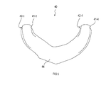
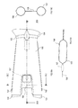
- the present invention is applicable to exhaust pipes 130 and 131 through which exhaust gas from the internal combustion engine 120 passes, and exhaust pipes 130 and 131, as shown in FIGS.
- the merging member 150 in the exhaust system 160 including the merging member 150 for merging and the exhaust pipes 133 and 134 for guiding the exhaust gas that has passed through the merging member 150 may be used.
- the joining member 150 includes pipe connection portions 151 and 152 to which the exhaust pipes 130 and 131 are connected, and pipe connection portions 153 and 154 to which the exhaust pipes 133 and 134 are connected.
- a confluence branching portion 155 that joins the exhaust gas from the pipe connecting portions 151 and 152 and leads to the pipe connecting portions 153 and 154, and a support portion 156 that connects the pipe connecting portion 151 and the pipe connecting portion 152. I have.
- the joining member 150 includes two outer shell members 158 and 159 that are plate members having depressions (concave portions), and these outer shell members 158 and 159 are joined together. Consists of.
- the pipe connecting portions 151 and 152, the pipe connecting portions 153 and 154, and the merging / dividing portion 155 are formed by joining the outer shell members 158 and 159, and are configured by the outer shell members 158 and 159.
- the support portion 156 is provided on either the outer shell member 158 or the outer shell member 159. In the example shown in FIGS. 10B and 10C, the support portion 156 is provided on the outer shell member 159.
- the support portion 156 includes a peripheral edge of the pipe connecting portions 151 and 152, a peripheral edge of the merging / dividing portion 155, and a peripheral edge of the support portion 156 in either one of the outer shell member 158 and the outer shell member 159 provided with the support portion 156.
- a portion surrounded by the periphery is provided so as to form an opening 157 having an opening.
- the merging member 150 According to the merging member 150, a part different from the merging member 150 attached to another device, a fastening part, or the like can be operated through the opening in the opening 157. As a result, according to the merging member 150, it is possible to improve workability at the time of work using these other parts and fastening parts. [Correspondence between Embodiment and Claims] Finally, the relationship between the description of the above embodiment and the description of the scope of claims will be described.
- the upper outer shell members 35 and 83, the lower outer shell members 45 and 90, and the intermediate outer shell member 40 in the above embodiment are examples of the first outer shell member and the second outer shell member in the description of the claims.
- the flange portions 12 and 72 correspond to an example of the flange portion in the claims.
- support portions 28, 88, and 89 in the above embodiment correspond to an example of the support portion in the description of the claims.
Landscapes
- Engineering & Computer Science (AREA)
- Chemical & Material Sciences (AREA)
- Combustion & Propulsion (AREA)
- Mechanical Engineering (AREA)
- General Engineering & Computer Science (AREA)
- Exhaust Silencers (AREA)
Priority Applications (3)
| Application Number | Priority Date | Filing Date | Title |
|---|---|---|---|
| CA2875766A CA2875766C (fr) | 2012-06-06 | 2013-05-31 | Element de systeme d'echappement |
| US14/406,157 US20150152770A1 (en) | 2012-06-06 | 2013-05-31 | Exhaust system component |
| CN201380029818.XA CN104350253A (zh) | 2012-06-06 | 2013-05-31 | 排气系统部件 |
Applications Claiming Priority (2)
| Application Number | Priority Date | Filing Date | Title |
|---|---|---|---|
| JP2012-128945 | 2012-06-06 | ||
| JP2012128945A JP5890257B2 (ja) | 2012-06-06 | 2012-06-06 | 排気系部品 |
Publications (1)
| Publication Number | Publication Date |
|---|---|
| WO2013183565A1 true WO2013183565A1 (fr) | 2013-12-12 |
Family
ID=49711957
Family Applications (1)
| Application Number | Title | Priority Date | Filing Date |
|---|---|---|---|
| PCT/JP2013/065239 Ceased WO2013183565A1 (fr) | 2012-06-06 | 2013-05-31 | Élément de système d'échappement |
Country Status (5)
| Country | Link |
|---|---|
| US (1) | US20150152770A1 (fr) |
| JP (1) | JP5890257B2 (fr) |
| CN (1) | CN104350253A (fr) |
| CA (1) | CA2875766C (fr) |
| WO (1) | WO2013183565A1 (fr) |
Cited By (1)
| Publication number | Priority date | Publication date | Assignee | Title |
|---|---|---|---|---|
| CN106224071A (zh) * | 2016-09-12 | 2016-12-14 | 奇瑞汽车股份有限公司 | 一种排气歧管总成 |
Families Citing this family (4)
| Publication number | Priority date | Publication date | Assignee | Title |
|---|---|---|---|---|
| PL3279359T3 (pl) * | 2015-03-31 | 2021-12-27 | Nippon Steel Stainless Steel Corporation | Element układu wydechowego zawierający blachę cienką ze stali nierdzewnej o doskonałych właściwościach w przypadku okresowego utleniania |
| CN108026822B (zh) * | 2016-06-20 | 2020-05-08 | 双叶产业株式会社 | 排气管 |
| JP6493464B2 (ja) | 2017-07-24 | 2019-04-03 | マツダ株式会社 | エンジンの排気装置 |
| CN112513437B (zh) * | 2018-05-15 | 2023-04-14 | 康明斯公司 | 双壁集成凸缘接头 |
Citations (7)
| Publication number | Priority date | Publication date | Assignee | Title |
|---|---|---|---|---|
| JPS6050217A (ja) * | 1983-08-31 | 1985-03-19 | Mazda Motor Corp | エンジンの排気マニホ−ルド |
| JPS6053611A (ja) * | 1983-08-31 | 1985-03-27 | Nissan Motor Co Ltd | 排気管の接続構造 |
| JPS637231U (fr) * | 1986-07-01 | 1988-01-18 | ||
| JPS6310219U (fr) * | 1986-07-04 | 1988-01-23 | ||
| JPH10252458A (ja) * | 1997-03-11 | 1998-09-22 | Yutaka Giken Co Ltd | 内燃機関の排気装置 |
| JP2005036724A (ja) * | 2003-07-15 | 2005-02-10 | Yumex Corp | 排気マニホールド |
| JP2011185120A (ja) * | 2010-03-05 | 2011-09-22 | Futaba Industrial Co Ltd | エギゾーストマニホルド |
Family Cites Families (14)
| Publication number | Priority date | Publication date | Assignee | Title |
|---|---|---|---|---|
| JP2819216B2 (ja) * | 1993-01-27 | 1998-10-30 | 株式会社ユタカ技研 | 排気マニホルド及びその製造方法 |
| DE59914322D1 (de) * | 1998-10-05 | 2007-06-14 | Scambia Ind Dev Ag | Abgasleitelement und Verfahren zur Herstellung eines Abgasleitelements |
| JP2002089282A (ja) * | 2000-09-18 | 2002-03-27 | Sango Co Ltd | 遮熱カバーの取付構造 |
| JP2002276356A (ja) * | 2001-03-19 | 2002-09-25 | Mazda Motor Corp | 車載用エンジンの排気構造 |
| DE102004021196B4 (de) * | 2004-04-29 | 2006-10-05 | J. Eberspächer GmbH & Co. KG | Luftspaltisolierter Abgaskrümmer |
| JP2007154660A (ja) * | 2005-11-30 | 2007-06-21 | Futaba Industrial Co Ltd | エギゾーストマニホルド |
| WO2007081669A2 (fr) * | 2006-01-03 | 2007-07-19 | Metaldyne Company, Llc | Tubulure d'échappement à paroi double et procédé de fabrication de celle-ci |
| JP2008121570A (ja) * | 2006-11-13 | 2008-05-29 | Toyota Motor Corp | 排気マニホルド |
| WO2008156695A1 (fr) * | 2007-06-13 | 2008-12-24 | Metaldyne Company Llc | Tubulure d'échappement présentant des caractéristiques nvh améliorées |
| DE102007062660A1 (de) * | 2007-12-24 | 2009-06-25 | J. Eberspächer GmbH & Co. KG | Abgaskrümmer |
| WO2009091540A1 (fr) * | 2008-01-14 | 2009-07-23 | Metaldyne Company Llc | Joint bicouche soudé à un rebord |
| JP2009257247A (ja) * | 2008-04-18 | 2009-11-05 | Futaba Industrial Co Ltd | エギゾーストマニホルド |
| DE102009011379B4 (de) * | 2009-03-05 | 2012-07-05 | Benteler Automobiltechnik Gmbh | Abgasbaugruppe |
| US8887496B2 (en) * | 2012-01-25 | 2014-11-18 | Ford Global Technologies, Llc | Heat recovery system for a vehicle |
-
2012
- 2012-06-06 JP JP2012128945A patent/JP5890257B2/ja not_active Expired - Fee Related
-
2013
- 2013-05-31 CN CN201380029818.XA patent/CN104350253A/zh active Pending
- 2013-05-31 US US14/406,157 patent/US20150152770A1/en not_active Abandoned
- 2013-05-31 CA CA2875766A patent/CA2875766C/fr not_active Expired - Fee Related
- 2013-05-31 WO PCT/JP2013/065239 patent/WO2013183565A1/fr not_active Ceased
Patent Citations (7)
| Publication number | Priority date | Publication date | Assignee | Title |
|---|---|---|---|---|
| JPS6050217A (ja) * | 1983-08-31 | 1985-03-19 | Mazda Motor Corp | エンジンの排気マニホ−ルド |
| JPS6053611A (ja) * | 1983-08-31 | 1985-03-27 | Nissan Motor Co Ltd | 排気管の接続構造 |
| JPS637231U (fr) * | 1986-07-01 | 1988-01-18 | ||
| JPS6310219U (fr) * | 1986-07-04 | 1988-01-23 | ||
| JPH10252458A (ja) * | 1997-03-11 | 1998-09-22 | Yutaka Giken Co Ltd | 内燃機関の排気装置 |
| JP2005036724A (ja) * | 2003-07-15 | 2005-02-10 | Yumex Corp | 排気マニホールド |
| JP2011185120A (ja) * | 2010-03-05 | 2011-09-22 | Futaba Industrial Co Ltd | エギゾーストマニホルド |
Cited By (1)
| Publication number | Priority date | Publication date | Assignee | Title |
|---|---|---|---|---|
| CN106224071A (zh) * | 2016-09-12 | 2016-12-14 | 奇瑞汽车股份有限公司 | 一种排气歧管总成 |
Also Published As
| Publication number | Publication date |
|---|---|
| JP2013253534A (ja) | 2013-12-19 |
| CA2875766C (fr) | 2017-02-07 |
| US20150152770A1 (en) | 2015-06-04 |
| JP5890257B2 (ja) | 2016-03-22 |
| CA2875766A1 (fr) | 2013-12-12 |
| CN104350253A (zh) | 2015-02-11 |
Similar Documents
| Publication | Publication Date | Title |
|---|---|---|
| WO2013183565A1 (fr) | Élément de système d'échappement | |
| JPH0543227Y2 (fr) | ||
| JP2005163623A (ja) | エキゾーストマニホールド | |
| JP4094423B2 (ja) | 内燃機関の排気装置 | |
| JP3509796B2 (ja) | エキゾーストマニホールド | |
| KR20030074170A (ko) | 배기 매니폴드 집합부 구조 | |
| US8857164B2 (en) | Exhaust manifold | |
| US20100011755A1 (en) | Collecting part structure of exhaust manifold | |
| US7866709B2 (en) | Crosstalk device for an exhaust system | |
| US8127539B2 (en) | Exhaust manifold | |
| JP4707699B2 (ja) | 内燃機関における排気マニホールド | |
| JP4665906B2 (ja) | 排気系部品及び排気系部品の製造方法 | |
| JP2003269158A (ja) | 内燃機関の排気マニホルド | |
| JP2007162509A (ja) | 内燃機関の排気通路構造、排気マニホルド、シリンダヘッド及び排気マニホルド用ガスケット | |
| JP2005256696A (ja) | 内燃機関の排気マニホルド | |
| JP2007309168A (ja) | エンジンの排気ガス還流装置 | |
| JP2006002686A (ja) | エンジンの排気管集合部の成形方法および排気管集合部 | |
| JP2005076605A (ja) | 二重構造排気システム | |
| KR20090064195A (ko) | 엔진의 배기파이프 구조 | |
| JP2005030247A (ja) | エンジンの排気装置 | |
| JP2004353583A (ja) | エキゾーストマニホールドの集合部構造 | |
| JP5187226B2 (ja) | 排気マニホールド及び排気装置 | |
| JP3047733B2 (ja) | 内燃機関の排気マニホールド | |
| JP2017115681A (ja) | エキゾーストマニホールド | |
| WO2005005816A1 (fr) | Collecteur d'echappement |
Legal Events
| Date | Code | Title | Description |
|---|---|---|---|
| 121 | Ep: the epo has been informed by wipo that ep was designated in this application |
Ref document number: 13800661 Country of ref document: EP Kind code of ref document: A1 |
|
| ENP | Entry into the national phase |
Ref document number: 2875766 Country of ref document: CA |
|
| WWE | Wipo information: entry into national phase |
Ref document number: 14406157 Country of ref document: US |
|
| NENP | Non-entry into the national phase |
Ref country code: DE |
|
| WWE | Wipo information: entry into national phase |
Ref document number: IDP00201407797 Country of ref document: ID |
|
| 122 | Ep: pct application non-entry in european phase |
Ref document number: 13800661 Country of ref document: EP Kind code of ref document: A1 |