WO2013183647A1 - Dispositif d'alimentation distribuée et dispositif de pesée de combinaison le comprenant - Google Patents
Dispositif d'alimentation distribuée et dispositif de pesée de combinaison le comprenant Download PDFInfo
- Publication number
- WO2013183647A1 WO2013183647A1 PCT/JP2013/065494 JP2013065494W WO2013183647A1 WO 2013183647 A1 WO2013183647 A1 WO 2013183647A1 JP 2013065494 W JP2013065494 W JP 2013065494W WO 2013183647 A1 WO2013183647 A1 WO 2013183647A1
- Authority
- WO
- WIPO (PCT)
- Prior art keywords
- trough
- article
- feeder
- angle
- articles
- Prior art date
- Legal status (The legal status is an assumption and is not a legal conclusion. Google has not performed a legal analysis and makes no representation as to the accuracy of the status listed.)
- Ceased
Links
Images





Classifications
-
- B—PERFORMING OPERATIONS; TRANSPORTING
- B65—CONVEYING; PACKING; STORING; HANDLING THIN OR FILAMENTARY MATERIAL
- B65G—TRANSPORT OR STORAGE DEVICES, e.g. CONVEYORS FOR LOADING OR TIPPING, SHOP CONVEYOR SYSTEMS OR PNEUMATIC TUBE CONVEYORS
- B65G27/00—Jigging conveyors
- B65G27/10—Applications of devices for generating or transmitting jigging movements
- B65G27/32—Applications of devices for generating or transmitting jigging movements with means for controlling direction, frequency or amplitude of vibration or shaking movement
-
- B—PERFORMING OPERATIONS; TRANSPORTING
- B65—CONVEYING; PACKING; STORING; HANDLING THIN OR FILAMENTARY MATERIAL
- B65G—TRANSPORT OR STORAGE DEVICES, e.g. CONVEYORS FOR LOADING OR TIPPING, SHOP CONVEYOR SYSTEMS OR PNEUMATIC TUBE CONVEYORS
- B65G47/00—Article or material-handling devices associated with conveyors; Methods employing such devices
- B65G47/22—Devices influencing the relative position or the attitude of articles during transit by conveyors
- B65G47/26—Devices influencing the relative position or the attitude of articles during transit by conveyors arranging the articles, e.g. varying spacing between individual articles
- B65G47/28—Devices influencing the relative position or the attitude of articles during transit by conveyors arranging the articles, e.g. varying spacing between individual articles during transit by a single conveyor
-
- G—PHYSICS
- G01—MEASURING; TESTING
- G01G—WEIGHING
- G01G19/00—Weighing apparatus or methods adapted for special purposes not provided for in the preceding groups
- G01G19/387—Weighing apparatus or methods adapted for special purposes not provided for in the preceding groups for combinatorial weighing, i.e. selecting a combination of articles whose total weight or number is closest to a desired value
- G01G19/393—Weighing apparatus or methods adapted for special purposes not provided for in the preceding groups for combinatorial weighing, i.e. selecting a combination of articles whose total weight or number is closest to a desired value using two or more weighing units
-
- B—PERFORMING OPERATIONS; TRANSPORTING
- B65—CONVEYING; PACKING; STORING; HANDLING THIN OR FILAMENTARY MATERIAL
- B65G—TRANSPORT OR STORAGE DEVICES, e.g. CONVEYORS FOR LOADING OR TIPPING, SHOP CONVEYOR SYSTEMS OR PNEUMATIC TUBE CONVEYORS
- B65G27/00—Jigging conveyors
- B65G27/08—Supports or mountings for load-carriers, e.g. framework, bases, spring arrangements
Definitions
- the present invention relates to a distributed supply device configured to supply articles to a plurality of hoppers arranged at the lower stage of the apparatus peripheral portion while radially distributing the articles supplied to the upper center of the apparatus to the peripheral portion of the apparatus,
- the present invention relates to a combination weighing device including a supply device.
- the combination weighing device having a circular shape in plan view is provided with a dispersion supply device A as shown in a partial cross-sectional view of FIG.
- a dispersion feeder DF is arranged at the upper center of the apparatus, and a plurality of radiation feeders RF are arranged radially around the dispersion feeder DF.
- the dispersion feeder DF has a conical diaphragm.
- the dispersion supply apparatus A disperses the articles G supplied on the dispersion feeder DF to the radiation feeders RF following the dispersion feeder DF, and distributes the articles G to the hoppers PH below the tips of the radiation feeders RF. Drain little by little.
- the weight of the article supplied to each hopper PH is detected by the lower weighing hopper WH, and the corresponding radiation feeder RF is based on the detection result. Are controlled individually.
- Patent Document 1 Japanese Patent Laid-Open No. 11-14439
- Patent Document 2 Japanese Utility Model Laid-Open No. 07-38927
- the present invention is intended to solve such a problem, and even if an article is deposited on the radiation feeder, a new distributed supply device that can transport the pile while crushing the pile without using a stirrer or the like. It is an object to provide a combination weighing device including the same.
- the distributed supply apparatus includes a distributed feeder and a plurality of radiation feeders.
- the dispersion feeder is disposed at the upper center of the apparatus and disperses the supplied articles.
- the plurality of radiating feeders are arranged radially around the dispersion feeder and individually discharge the articles that are dispersed and flown by the dispersion feeder.
- Each radiation feeder includes a trough and a vibration device. The trough conveys the article. The vibration exciter vibrates the trough back and forth in a direction inclined with respect to the article transport surface.
- the conveyance speed of the article conveyed by the vibration device is set so that it is fast at the front part of the trough and slow at the rear part, and the speed component that jumps in the vertical direction of the article is the front part of the trough. Is characterized by being set to be large and small at the rear.
- the conveyance speed of the pile of articles conveyed by the trough is faster at the front part of the trough than the rear part of the trough, and the speed component that jumps in the vertical direction is also higher at the front part of the trough than the rear part of the trough. Is bigger.
- the pile of articles deposited on the trough extends forward while being collapsed at the front of the trough, and the overlap between the articles decreases. Even if the article is accumulated at the rear end portion of the trough, it is flattened while being broken in the process of being conveyed to the front end portion, so that an appropriate amount of the article is supplied to the hopper.
- the vibration device vibrates the trough so that the article at the front of the trough is flipped up at the first jump angle toward the front of the trough, and the article at the rear of the trough is in front of the trough. It is preferable to vibrate the trough so as to be raised at the second flip-up angle.
- the second flip-up angle is an angle smaller than the first flip-up angle.
- the first flip-up angle is preferably 30 ° to 45 °
- the second flip-up angle is preferably 10 ° to 20 °. Accordingly, the article on the trough can be sufficiently separated in the front-rear direction, and the conveyance efficiency of the article can be improved.
- the vibration device preferably has a movable core, an electromagnet, and a pair of front and rear leaf springs.
- the movable core is fixed to a base portion to which the trough is attached.
- the electromagnet is attached in the vicinity of the counterweight and attracts the movable core.
- a pair of front and rear leaf springs connect the trough and the counterweight.
- the first leaf spring preferably has an inclination of 75 ° with respect to the horizontal plane
- the second leaf spring preferably has an inclination of 74 ° with respect to the horizontal plane.
- the first leaf spring is a leaf spring positioned on the front side in the article conveyance direction of the pair of front and rear leaf springs, and the second leaf spring is located on the rear side in the article conveyance direction in the pair of front and rear leaf springs. It is a leaf spring located. Thereby, suitable vibration can be given to the trough by the vibration exciter.
- the combination weighing device includes the distributed supply device according to the present invention, a plurality of pool hoppers, and the same number of weighing hoppers as the pool hoppers.
- the plurality of pool hoppers are disposed at the lower ends of the tips of the respective radiation feeders and receive articles discharged from the respective radiation feeders.
- the weighing hopper is arranged at the lower stage of the radiation feeder, and receives and weighs the articles discharged from each pool hopper.
- the present invention even if an article is deposited on the radiation feeder, it can be conveyed while collapsing the pile of the deposited article without using a stirrer or the like. Therefore, it is possible to avoid excessive supply to the lower hoppers. In addition, it is possible to effectively suppress the deterioration of the weighing accuracy, the decrease in the operation rate of the combination weighing device, and the like caused by excessive supply of articles.
- action of this invention is a schematic configuration diagram of a combination weighing device according to an embodiment of the present invention.
- FIG. 3 is a schematic diagram of a main part of the combination weighing device 1 according to an embodiment of the present invention.
- the combination weighing device 1 includes a distributed supply device 100, a pool hopper PH, and a weighing hopper WH.
- the distributed supply device 100 mainly includes a distributed feeder 10 and a plurality of radiation feeders (electromagnetic feeders) 20.
- the dispersion feeder 10 is disposed at the upper center of the apparatus.
- the plurality of radiation feeders 20 are arranged radially around the dispersion feeder 10 so as to surround the dispersion feeder 10.
- the dispersion feeder 10 includes a conical diaphragm 11 and a vibration mechanism 12.
- the vibration mechanism 12 reciprocates the vibration plate 11 up and down spirally. Due to the spiral motion of the diaphragm 11, the articles G dropped on the diaphragm 11 are dispersed in the circumferential direction.
- the dispersion feeder 10 is supported by the weight detector 13. The weight detector 13 detects the weight of the article G dropped on the vibration plate 11.
- the output of the weight detector 13 is constantly monitored by the control unit 30.
- the control unit 30 drives the upstream cross feeder CF to drop the article G onto the vibration plate 11.
- the control unit 30 stops the cross feeder CF.
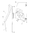
- FIGS. 4A and 4B show a radiation feeder (electromagnetic feeder) according to this embodiment.
- the radiation feeder 20 shown in FIGS. 4A and 4B includes a trough T, a vibration exciter, a movable block 21, and vibration isolation springs 24 and 25.
- the vibration device includes a pair of front and rear leaf springs S1 and S2 and a vibration mechanism B.
- the vibration mechanism B includes a movable core 22 and an electromagnet 23.
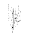
- FIGS. 1 and 2 are schematic views of a radiation feeder (electromagnetic feeder) for explaining the operation of the present invention.
- the radiation feeder shown in FIGS. 1 and 2 includes a trough T, a vibration exciter, and a vibration isolation spring. That is, FIG. 1 and FIG. 2 show a radiation feeder that does not have the movable block 21 as an essential configuration.
- the vibration device included in the radiation feeder shown in FIGS. 1 and 2 also includes a pair of front and rear leaf springs S1 and S2 and a vibration mechanism B.
- the vibration mechanism B includes a movable core B1 and an electromagnet B2.
- the trough T carries the article G.
- the vibration device is a device that applies vibration to the trough T.
- the vibration mechanism B included in the vibration device swings the plate springs S1 and S2 back and forth around the attachment position of the plate springs S1 and S2 with respect to the counterweight CW.
- a pair of front and rear leaf springs S1, S2 connect the trough T and the counterweight CW.
- the movable cores B1, 22 are made of a magnetic material.
- the movable core 22 is fixed to the bottom surface of the movable block 21.
- the movable core B ⁇ b> 1 is fixed to the base portion TB to which the trough T is attached.
- the electromagnet 23 is disposed opposite to the movable core 22 with a predetermined gap. Further, the electromagnet 23 is fixed in a forward leaning posture in the middle of the counterweight CW. On the other hand, in the radiation feeder shown in FIGS. 1 and 2, the electromagnet B2 is attached to the counterweight CW side and attracts the movable core B1.
- the bottom of the trough T and the upper ends of the leaf springs S1, S2 are attached to the movable block 21.
- the movable block 21 is not an essential configuration of the radiation feeder (see FIGS. 1 and 2).
- the anti-vibration springs 24 and 25 are springs having a low spring constant.
- the anti-vibration springs 24 and 25 support the entire radiation feeder 20.
- an electromagnetic type is adopted as the vibration mechanism.
- the present invention is not limited to such an electromagnetic vibration mechanism.
- piezoelectric elements are attached to both surfaces of the front and rear plate springs S1 and S2.
- the leaf springs S1 and S2 themselves may be vibrated back and forth.
- the trough T and the movable block 21 are provided with dish-like members 26 and 27 at opposite positions.
- a trough T is attached to the movable block 21 by attaching a tightening ring (not shown) to the flange portion of each plate-like member 26 and 27. It is designed to be firmly fixed. Further, when the trough T is removed from the movable block 21, the two can be separated by removing the winding ring.
- a folded portion T1 for preventing leakage of the article is formed, from which the trough side plates T2 and T3 spread in a fan shape toward the front. This is to prevent the article from leaking between the troughs T arranged radially. Therefore, the upper edge of one side plate T2 is bent in a mountain shape so as to cover the other side plate T3 of the adjacent trough T.
- the attachment angles ⁇ 3 and ⁇ 4 of the leaf springs S1 and S2 are changed, and the line connecting the center of gravity of the trough T and the center of gravity of the counterweight CW is adjusted so as to intersect the vibration direction of the trough T. It is possible to Thereby, the conveyance speed of the article located at the front part of the trough T is made faster than the conveyance speed of the article located at the rear part, and the speed component jumping in the vertical direction is also made larger at the front part than at the rear part. be able to.
- the vibration direction of the trough T is a vibration obtained by combining the vibration in the direction D1 at the upper end of the leaf spring S1 and the vibration in the direction D2 at the upper end of the leaf spring S2.
- accelerometers are attached to a plurality of locations on the trough T.
- the direction of the maximum acceleration (arrow directions A1, A2) at each attached point is ⁇ 1> ⁇ 2.
- the inclination angles ⁇ 3 and ⁇ 4 of the leaf springs S1 and S2, the attachment position, the gravity center position of the trough T, the gravity center position of the counterweight CW, and the like are adjusted. Then, the article G on the trough T jumps up in the detected maximum acceleration direction ( ⁇ 1, ⁇ 2).
- the direction of the maximum acceleration measured at the location on the downstream side of the trough T is larger than the direction of the maximum speed measured at the location on the upstream side of the trough T with respect to the conveyance surface of the article G. So that the inclination angles ⁇ 3 and ⁇ 4 of the leaf springs S1 and S2, the attachment position, the gravity center position of the trough T, the gravity center position of the counterweight CW, and the like are adjusted.
- the magnitude of the inclination of the article G with respect to the conveyance surface in the direction of the maximum acceleration corresponds to the magnitude of the flip-up angle of the article G with respect to the conveyance surface, which will be described later.
- the spring constant of the rear leaf spring S2 is made smaller than the spring constant of the front leaf spring S1.
- the inclination angle ⁇ 3 with respect to the vertical axis of the front leaf spring S1 is made smaller than the inclination angle ⁇ 4 with respect to the vertical axis of the rear leaf spring S2.
- the inclination angle ⁇ 3 is 15 °
- the inclination angle ⁇ 4 is 16 °. In other words, the angle from the horizontal plane to the front leaf spring S1 is larger than the angle from the horizontal plane to the rear leaf spring S2.
- the angle from the horizontal plane to the front leaf spring S1 is 75 °
- the angle from the horizontal plane to the rear leaf spring S2 is 74 °.
- the first flip-up angle and the second flip-up angle are angles within a predetermined range, respectively.
- the first flip-up angle is 30 ° to 45 °
- the second flip-up angle is 10 ° to 20 °.
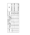
- FIG. 7 shows the relationship between the flip-up angle and the transport state obtained by vibrating each of the plural types of troughs.
- FIG. 7 shows a flip-up angle of each trough T at a predetermined position and a transport state of the article G transported at the flip-up angle.
- the predetermined positions are the front end FE and the rear end RE of the trough T (see FIG. 4B).
- the front end FE of the trough T is an end portion on the front side of the trough T, and is an end portion on the most downstream side in the conveyance direction of the article G.
- the rear end RE of the trough T is an end portion on the rear side of the trough T and is an end portion on the most upstream side in the conveyance direction of the article G.
- the conveyance state is good.
- the conveyance state is poor as compared with the case where the first and second flip-up angles are included in the predetermined ranges described above.
- the conveyance state is poor when the separation of the article at the front part of the trough T with respect to the article at the rear part of the trough T is insufficient or the conveyance speed of the article G at the trough T is insufficient. means.
- the article G positioned in front of the trough T jumps up at an angle of about 35 ° in the direction of the arrow A3, and the article G positioned at the center is about 25 ° in the direction of the arrow A4.
- the article G that jumps up at an angle of and is located behind is designed to jump up at an angle of about 15 ° in the direction of arrow A5. That is, in the radiation feeder 20 shown in FIG. 4A, the flip-up angle of the article G positioned in front of the trough T is 35 °, and the flip-up angle of the article G positioned in the center of the trough T is 25 °.
- the flip-up angle of the article G located behind the trough T is 15 °.
- the article at the front of the trough T has a higher conveying speed and a higher speed component that jumps in the vertical direction, so that the article moves forward at a higher speed than the article at the rear of the trough T. become.
- a pool hopper PH is provided at the lower end portion of each radiation feeder 20. Further, a weighing hopper WH is provided below the pool hopper PH. The article G discharged from the radiation feeder 20 is temporarily stocked by the pool hopper PH. When the weighing hopper WH below the pool hopper PH becomes empty, the gate g of the upper pool hopper PH is opened and closed, and the article G is discharged to the lower weighing hopper WH.
- each weighing hopper WH is provided with a weight detector WS.
- the weight detected by the weight detector WS is input to the control unit 30 and used for combination calculation and control of the radiation feeder 20. Since each hopper PH, WH has a known configuration, a gate opening / closing mechanism, a support mechanism for the hopper PH, WH, and the like are omitted here.
- the control unit 30 When an operation key (not shown) is operated in a state where the article G is not put into the distributed supply device 100, the control unit 30 inputs the weight from the weight detector WS of the weighing hopper WH and checks the presence / absence of the article. . At first, since any hopper PH, WH is empty, the control unit 30 opens and closes the gate g of each pool hopper PH, and then sets each radiation feeder 20 and the dispersion feeder 10 to the set vibration intensity. And drive based on vibration time.
- the control unit 30 inputs the weight of the article loaded on the dispersion feeder 10 by the weight detector 13 of the dispersion feeder 10 and checks the loading amount of the article G on the dispersion feeder 10. If the loading amount of the article G loaded on the dispersion feeder 10 is below the lower limit level, the cross feeder CF is driven. On the other hand, when the loading amount of the article G loaded on the dispersion feeder 10 reaches the upper limit level, the cross feeder CF is stopped. However, since there is no article in the dispersion feeder 10 at the beginning, the control unit 30 opens / closes each hopper PH and drives each of the feeders 10 and 20 while driving the cross feeder CF. repeat. As such, the article G sequentially flows to the dispersion feeder 10, the radiation feeder 20, and the pool hopper PH, and is supplied to the weighing hopper WH.
- the control unit 30 inputs the article weight of each weighing hopper WH and executes a combination calculation.
- the gates g of the weighing hoppers WH corresponding to the optimum combination are opened and closed to collect articles. It is discharged to the chute S.
- the gate g of the pool hopper PH corresponding to the empty weighing hopper WH is opened and closed, and the article is discharged to the empty weighing hopper WH.
- the radiation feeder 20 and the dispersion feeder 10 corresponding to the pool hopper PH are driven, and the articles are discharged from the radiation feeder 20 to the empty pool hopper PH.
- the control unit 30 determines the vibration intensity and vibration time of the radiation feeder 20 corresponding to each weighing hopper WH based on the average value of the article weights input from the weight detector WS of each weighing hopper WH. Will be adjusted individually. That is, every time the optimum combination is selected from the 10 weighing hoppers WH, 3 to 4 weighing hoppers WH are selected as the optimum combinations, and the total weight of articles discharged from them is substantially equal to the target weight. As described above, the vibration intensity and the vibration time of each radiation feeder 20 are individually adjusted.
- the control unit 30 performs a target weight in which the amount of articles supplied from the dispersion feeder 10 toward the radiation feeder 20 is selected in combination at one time from the start of driving to the end of driving.
- the vibration intensity and the vibration time of the dispersion feeder 10 are adjusted so as to be substantially equal to.
- the combination weighing operation is stabilized each time, and the operating rate of the device is improved.
- the upstream article supply amount varies or the weighing hopper WH selected for the combination is biased, the radiation feeder 20 corresponding to the weighing hopper WH that is not selected is not driven and is not driven. Goods flow. Therefore, articles accumulate on the stepped portion between the radiating feeder 20 and the dispersion feeder 10, which is the upstream portion of the radiating feeder 20.
- the articles G in the front part of the trough T and the articles G in the rear part of the trough T are different with respect to the conveyance direction of the article G.
- the trough T is vibrated so as to be flipped up at an angle. Specifically, the article G at the front portion of the trough T is flipped forward at the first flip-up angle with respect to the conveyance direction of the article G toward the front of the trough T, and the article G at the rear portion of the trough T is It is flipped up at the second flip-up angle with respect to the conveyance direction of the article G toward the front of T.
- the second flip-up angle is an angle smaller than the first flip-up angle.
- the article G at the front part of the trough T and the article G at the rear part of the trough T can be suitably separated. As a result, it is possible to prevent the mass of the article G from dropping from the trough T with respect to the pool hopper PH.
- the article G in front of the trough T is flipped up at an angle of 30 ° to 45 °, and the article G behind the trough T has an angle of 10 ° to 20 °. You can jump up. Thereby, the article G on the trough can be sufficiently separated in the front-rear direction, and the conveyance efficiency of the article G can be improved.
- the vibration device includes the movable core 22, the electromagnet 23, and a pair of front and rear leaf springs S1, S2.
- the movable core 22 is fixed to a base portion to which the trough T is attached.
- the electromagnet 23 is attached in the vicinity of the counterweight CW (or the counterweight CW) and attracts the movable core 22.
- a pair of front and rear leaf springs S1, S2 connect the trough T and the counterweight CW.
- the first leaf spring S1 disposed on the front side in the conveyance direction of the article G has an inclination of 75 ° with respect to the horizontal plane, and the second leaf spring S2 on the rear side in the conveyance direction of the article G is in the horizontal plane. It has an inclination of 74 °.
- the two leaf springs S1 and S2 arranged before and after the conveyance direction of the article G are attached so as to have different inclinations with respect to the horizontal plane, whereby the article G positioned at each of the front part and the rear part of the trough T is attached. It can be flipped up at different angles with respect to the conveying direction of the article. That is, a suitable vibration can be applied to the trough T by the vibration device according to the embodiment.
- the trough T is vibrated so that the piles of the articles G deposited on the trough T are collapsed in the distributed supply device 100. Therefore, even if the article G becomes coarse and dense on the dispersion feeder 11 due to a change in the quantity of the article G supplied from the cross feeder CF, the quantity of the article G in the process of being conveyed by the radiation feeder is It is made uniform. As a result, it is possible to avoid a situation in which a large amount of articles G are supplied to the downstream pool hopper PH at once.
- the combination weighing device combines the weights of articles.
- the present invention is not limited to this, and the number of articles supplied to each hopper PH, WH. Even a combination based on the above can be applied in the same manner.
- Combination Weighing Device 10 Dispersion Feeder 20 Radiation Feeder (Electromagnetic Feeder) 100 Distributed supply device T Trough G Article B Excitation mechanism (Excitation device) PH Pool hopper WH Weighing hopper S1 Leaf spring S2 Leaf spring ⁇ 1 Angle that the front article jumps up ⁇ 2 Angle that the rear article jumps up
Landscapes
- Engineering & Computer Science (AREA)
- Mechanical Engineering (AREA)
- Physics & Mathematics (AREA)
- General Physics & Mathematics (AREA)
- Jigging Conveyors (AREA)
- Feeding Of Articles To Conveyors (AREA)
Abstract
La présente invention s'attaque au problème consistant à fournir un nouveau dispositif d'alimentation distribuée (100) apte à transporter des biens (G) en aval tout en brisant les groupes empilés de biens sans utiliser d'agitateur ou analogue, même lorsque les biens sont empilés dans une partie amont d'un distributeur rayonnant (20), et un dispositif de pesée de combinaison (1) comprenant le dispositif d'alimentation distribuée. Le distributeur rayonnant (20) comprend une auge (T) pour transporter les biens (G) et un dispositif de stimulation (B) pour faire vibrer l'auge (T) vers l'avant et vers l'arrière dans une direction d'inclinaison de l'auge par rapport à une surface de transport de biens, la vitesse de transport des biens (G) transportés par le dispositif de stimulation (B) étant réglée de façon à être rapide dans la partie avant de l'auge (T) et lente dans la partie arrière.
Applications Claiming Priority (2)
| Application Number | Priority Date | Filing Date | Title |
|---|---|---|---|
| JP2012-126649 | 2012-06-04 | ||
| JP2012126649A JP2015158363A (ja) | 2012-06-04 | 2012-06-04 | 分散供給装置とそれを備えた組合せ計量装置 |
Publications (1)
| Publication Number | Publication Date |
|---|---|
| WO2013183647A1 true WO2013183647A1 (fr) | 2013-12-12 |
Family
ID=49712036
Family Applications (1)
| Application Number | Title | Priority Date | Filing Date |
|---|---|---|---|
| PCT/JP2013/065494 Ceased WO2013183647A1 (fr) | 2012-06-04 | 2013-06-04 | Dispositif d'alimentation distribuée et dispositif de pesée de combinaison le comprenant |
Country Status (2)
| Country | Link |
|---|---|
| JP (1) | JP2015158363A (fr) |
| WO (1) | WO2013183647A1 (fr) |
Cited By (2)
| Publication number | Priority date | Publication date | Assignee | Title |
|---|---|---|---|---|
| US20190162586A1 (en) * | 2017-11-29 | 2019-05-30 | Ishida Co., Ltd. | Hopper and combination weighing device equipped therewith |
| CN114076633A (zh) * | 2020-08-20 | 2022-02-22 | 梅特勒-托利多(常州)测量技术有限公司 | 定量称重设备的能效测量方法 |
Families Citing this family (1)
| Publication number | Priority date | Publication date | Assignee | Title |
|---|---|---|---|---|
| JP7667420B2 (ja) * | 2021-06-01 | 2025-04-23 | シンフォニアテクノロジー株式会社 | 振動搬送装置、制御装置 |
Citations (3)
| Publication number | Priority date | Publication date | Assignee | Title |
|---|---|---|---|---|
| JPS636444B2 (fr) * | 1978-06-05 | 1988-02-09 | Fmc Corp | |
| JP2002046842A (ja) * | 2000-08-02 | 2002-02-12 | Taisei Kiko Kk | 部品供給装置 |
| JP2010064817A (ja) * | 2008-09-09 | 2010-03-25 | Yamato Scale Co Ltd | 組合せ秤の物品搬送装置 |
-
2012
- 2012-06-04 JP JP2012126649A patent/JP2015158363A/ja active Pending
-
2013
- 2013-06-04 WO PCT/JP2013/065494 patent/WO2013183647A1/fr not_active Ceased
Patent Citations (3)
| Publication number | Priority date | Publication date | Assignee | Title |
|---|---|---|---|---|
| JPS636444B2 (fr) * | 1978-06-05 | 1988-02-09 | Fmc Corp | |
| JP2002046842A (ja) * | 2000-08-02 | 2002-02-12 | Taisei Kiko Kk | 部品供給装置 |
| JP2010064817A (ja) * | 2008-09-09 | 2010-03-25 | Yamato Scale Co Ltd | 組合せ秤の物品搬送装置 |
Cited By (5)
| Publication number | Priority date | Publication date | Assignee | Title |
|---|---|---|---|---|
| US20190162586A1 (en) * | 2017-11-29 | 2019-05-30 | Ishida Co., Ltd. | Hopper and combination weighing device equipped therewith |
| CN109835505A (zh) * | 2017-11-29 | 2019-06-04 | 株式会社石田 | 料斗以及具备料斗的组合计量装置 |
| EP3492885A1 (fr) * | 2017-11-29 | 2019-06-05 | ISHIDA CO., Ltd. | Trémie et dispositif de pesée par combinaison en étant équipé |
| US10876885B2 (en) | 2017-11-29 | 2020-12-29 | Ishida Co., Ltd. | Hopper with gap-closing edge portions |
| CN114076633A (zh) * | 2020-08-20 | 2022-02-22 | 梅特勒-托利多(常州)测量技术有限公司 | 定量称重设备的能效测量方法 |
Also Published As
| Publication number | Publication date |
|---|---|
| JP2015158363A (ja) | 2015-09-03 |
Similar Documents
| Publication | Publication Date | Title |
|---|---|---|
| US10059536B2 (en) | Particulate material supplying apparatus with a downwardly slanting discharge gutter which rotates side to side | |
| JP5976123B2 (ja) | ペレット投入装置 | |
| WO2013183647A1 (fr) | Dispositif d'alimentation distribuée et dispositif de pesée de combinaison le comprenant | |
| JP5366493B2 (ja) | 組合せ秤の物品搬送装置 | |
| WO2007034859A1 (fr) | Dispositif de mesure combiné | |
| JP2013220883A (ja) | 供給装置 | |
| JP5606036B2 (ja) | 振動フィーダの制御方法及び振動フィーダ装置と組合せ秤 | |
| JP2011232202A (ja) | 組合せ計量装置 | |
| JP4343937B2 (ja) | 組合せ計量装置 | |
| JP4651130B2 (ja) | 組合せ計量装置 | |
| JP2011256023A (ja) | 直進フィーダ及びそれを用いた組合せ秤 | |
| JP5248246B2 (ja) | 組合せ秤の物品搬送装置 | |
| JP6157922B2 (ja) | 組合せ秤の物品搬送構造 | |
| JP2021047022A (ja) | 計量装置の物品整列装置 | |
| JP7669100B2 (ja) | 分散トレイ及びこれを備えた組合せ秤 | |
| JP5080994B2 (ja) | 組合せ計量装置 | |
| JP4021933B2 (ja) | 組合せ計量・計数装置 | |
| JP5933657B2 (ja) | 供給装置 | |
| US20240344876A1 (en) | Weighing machine | |
| JP4440757B2 (ja) | 味付け装置 | |
| JP6244122B2 (ja) | 組合せ計量装置 | |
| JP2020143906A (ja) | 直進フィーダ用のトラフ及びこれを備えた組合せ秤 | |
| JP2019035601A (ja) | トラフ、供給フィーダ及び計量装置 | |
| JP6555999B2 (ja) | 供給装置 | |
| JP2018141690A (ja) | 粉粒体の定量フィーダ装置 |
Legal Events
| Date | Code | Title | Description |
|---|---|---|---|
| 121 | Ep: the epo has been informed by wipo that ep was designated in this application |
Ref document number: 13800448 Country of ref document: EP Kind code of ref document: A1 |
|
| NENP | Non-entry into the national phase |
Ref country code: DE |
|
| 122 | Ep: pct application non-entry in european phase |
Ref document number: 13800448 Country of ref document: EP Kind code of ref document: A1 |
|
| NENP | Non-entry into the national phase |
Ref country code: JP |