WO2013186939A1 - ショット処理装置 - Google Patents
ショット処理装置 Download PDFInfo
- Publication number
- WO2013186939A1 WO2013186939A1 PCT/JP2012/069177 JP2012069177W WO2013186939A1 WO 2013186939 A1 WO2013186939 A1 WO 2013186939A1 JP 2012069177 W JP2012069177 W JP 2012069177W WO 2013186939 A1 WO2013186939 A1 WO 2013186939A1
- Authority
- WO
- WIPO (PCT)
- Prior art keywords
- projection material
- shot
- projection
- workpiece
- processing apparatus
- Prior art date
- Legal status (The legal status is an assumption and is not a legal conclusion. Google has not performed a legal analysis and makes no representation as to the accuracy of the status listed.)
- Ceased
Links
Images


Classifications
-
- B—PERFORMING OPERATIONS; TRANSPORTING
- B24—GRINDING; POLISHING
- B24C—ABRASIVE OR RELATED BLASTING WITH PARTICULATE MATERIAL
- B24C9/00—Appurtenances of abrasive blasting machines or devices, e.g. working chambers, arrangements for handling used abrasive material
- B24C9/006—Treatment of used abrasive material
-
- B—PERFORMING OPERATIONS; TRANSPORTING
- B24—GRINDING; POLISHING
- B24C—ABRASIVE OR RELATED BLASTING WITH PARTICULATE MATERIAL
- B24C1/00—Methods for use of abrasive blasting for producing particular effects; Use of auxiliary equipment in connection with such methods
- B24C1/10—Methods for use of abrasive blasting for producing particular effects; Use of auxiliary equipment in connection with such methods for compacting surfaces, e.g. shot-peening
-
- Y—GENERAL TAGGING OF NEW TECHNOLOGICAL DEVELOPMENTS; GENERAL TAGGING OF CROSS-SECTIONAL TECHNOLOGIES SPANNING OVER SEVERAL SECTIONS OF THE IPC; TECHNICAL SUBJECTS COVERED BY FORMER USPC CROSS-REFERENCE ART COLLECTIONS [XRACs] AND DIGESTS
- Y02—TECHNOLOGIES OR APPLICATIONS FOR MITIGATION OR ADAPTATION AGAINST CLIMATE CHANGE
- Y02P—CLIMATE CHANGE MITIGATION TECHNOLOGIES IN THE PRODUCTION OR PROCESSING OF GOODS
- Y02P70/00—Climate change mitigation technologies in the production process for final industrial or consumer products
- Y02P70/10—Greenhouse gas [GHG] capture, material saving, heat recovery or other energy efficient measures, e.g. motor control, characterised by manufacturing processes, e.g. for rolling metal or metal working
Definitions
- the present invention generally relates to a shot processing apparatus, and more particularly to a shot processing apparatus that collects a projecting projection material and separates foreign matter from the collected projection material.
- the present invention has been made to solve the above-described problems, and an object of the present invention is to provide a shot processing apparatus capable of accurately separating the recovered projection material and foreign matter while suppressing an increase in the size of the apparatus. To do.
- a projector that projects a projection material onto the workpiece;
- a wind power selection mechanism that freely drops the collected projection material while applying an upward air flow to the collected projection material, and separates foreign matter mixed in the collected projection material from the collected projection material
- a shot processing apparatus is provided.
- the projection material (the mixture of the projection material and the foreign material) collected after being projected by the projector is allowed to fall freely and the upward airflow is applied, so that the sorting is accurate.
- the selection accuracy is improved by increasing the time during which the mixture of the projection material and the foreign matter is exposed to the airflow.
- the wind power selection mechanism is A free fall zone in which the upward airflow is generated and the collected projection material is allowed to fall freely; A lowermost portion communicating with the free fall zone through an opening, and a supply unit to which the recovered projection material is supplied,
- the opening is inclined so as to extend obliquely downward toward the free fall zone of the supply plate, a restriction plate disposed in the vertical direction toward the free fall zone of the supply portion, and a lower end of the restriction plate and the free fall zone of the supply portion It is formed between the parts.
- the flow rate is regulated by the regulation plate and is expanded in the plate width direction of the regulation plate. It falls in the free fall zone in a state of expanding in the width direction, and as a result, separation of foreign matters by the air current is promoted.
- the wind power selection mechanism is A plurality of dispersing rods are provided across the free fall zone.
- the shot processing apparatus having such a configuration, when the recovered projection material is freely dropped, it is dispersed by a plurality of dispersion rods, and an appropriate space is generated between the falling projection materials.
- the upward airflow flows almost uniformly between the falling projection materials, and the selection (classification) of the mixture by the upward airflow becomes easy.
- a concave receiving portion for receiving the projectile that has fallen freely.
- the projecting material once stops at the receiving portion before colliding with the lower member of the free fall zone. Wear is suppressed.
- the wind power sorting mechanism includes a centling chamber portion communicating above the free fall zone, In the centling chamber section, the foreign matter is caused to generate a detour flow by a guide plate, and is separated into a powdery substance put on the detour flow and a falling granular material.
- the light-weight material in the foreign material can be separated into the powdery material put on the detour flow and the falling granular material by the settling chamber.
- a projection chamber into which the projection material is projected is formed inside, a cabinet having a projection chamber inlet for carrying the workpiece into the projection chamber and a projection chamber outlet for carrying out the workpiece from the projection chamber;
- a first shot curtain device for dropping the projection material in a curtain shape from the upper part of the projection chamber entrance;
- a second shot curtain device for dropping the projection material in a curtain form from the upper part of the projection chamber outlet;
- a recovery mechanism for recovering the projected projection material from the projection chamber;
- a distribution box that distributes the projection material collected by the collection mechanism to the wind sorting mechanism, the first shot curtain device, and the second shot curtain device;
- the projection material projected in the projector by the projection material continuously dropped from the first shot curtain device and the second shot curtain device causes the projection chamber entrance and the projection chamber exit. Jumping out of or preventing is prevented.
- the projected projection material is distributed by the distribution device to the wind sorting mechanism, the first shot curtain device, and the second shot curtain device, the amount of the projection material supplied to the wind sorting mechanism is optimized. Therefore, the increase in size of the wind sorting mechanism and the dust collector can be suppressed.
- the projection material from which foreign matter has been separated by the wind power sorting mechanism is supplied to the projector.
- the projection material from which foreign matter has been removed can be reused in the projector.
- a transport means for transporting the workpiece to a position where the projection material is projected from the projector is A chain conveyor having an endless chain that is rotationally driven and a carrier that is attached to the outer peripheral side of the chain and supports the workpiece; A pair of rotation rollers disposed on both sides of the carrier in the conveyance direction of the carrier and capable of rotating and swinging about an axis extending in the conveyance direction of the workpiece.
- the workpiece placed on the rotation roller is rotated by the rotation of the rotation roller, the projection material is projected on the entire surface of the workpiece, and uniform shot processing is performed.
- a change adjustment mechanism for changing and adjusting the distance between the pair of rotation rollers is provided.
- the distance between the pair of rotation rollers can be set according to the size of the workpiece, so that the vertical length of the carrier can be suppressed.
- the distance between the pair of rotation rollers can be changed and adjusted, workpieces with various outer diameters can be placed on the pair of rotation rollers, so shot processing is performed on workpieces with various outer diameters. Can do.
- the bottom surface of the shot processing apparatus is formed flat.
- the shot processing apparatus having such a configuration, it is not necessary to dig a pit, and labor and cost during installation can be reduced.
- a calculation unit that compares the operating time of the consumables provided in the shot processing device with a preset lifetime and calculates the replacement time of the consumables, and a display capable of displaying the calculation results of the calculation unit And a control device having a unit.
- the shot processing apparatus having such a configuration, it is possible to easily grasp the life of the consumables.
- a storage unit that receives information on replacement history of consumables provided in the shot processing apparatus and stores the replacement history information, and a display unit that can display the replacement history information stored in the storage unit.
- the control apparatus which has is provided.
- the shot processing apparatus having such a configuration, it is possible to easily grasp the replacement history of the consumables of the shot apparatus.
- a shot processing apparatus capable of accurately separating the recovered projection material and foreign matters while suppressing an increase in size of the apparatus.
- FIG. 4 is a view showing a separator of the shot peening apparatus of FIG. 1
- FIG. 4 (A) is a cross-sectional view taken along line 4A-4A of FIG. 4 (B)
- FIG. 4 (B) is a front view of the separator.
- FIG. 5 (A) is a front view
- FIG.5 (B) is a side view.
- FIG. 5 (A) is a front view which shows the conveyance state of the workpiece
- a shot peening apparatus which is a shot processing apparatus according to an embodiment of the present invention, will be described with reference to FIGS.
- FIG. 1 shows the shot peening apparatus 10 in a front view
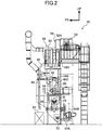
- FIG. 2 shows the shot peening apparatus 10 in a right side view
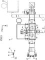
- FIG. 3 shows the shot peening apparatus 10 in a plan view.
- the workpiece W of the shot peening apparatus 10 according to the present embodiment is a cylindrical product such as a coil spring. Note that an arrow D appropriately shown in the drawing indicates a conveyance direction in which the workpiece W is conveyed.
- the shot peening apparatus 10 includes a cabinet 12.
- the cabinet 12 divides the internal space and the external space of the shot peening apparatus 10 so that steel balls used as a projection material (shot or shot material) in the cabinet 12 do not scatter to the outside of the shot peening apparatus 10. It has an outer wall. Further, the bottom surface of the lower part of the device is formed flat, that is, set so that the height in the vertical direction of the device is the same.
- the cabinet 12 includes a cabinet body 14 at an intermediate portion in the conveyance direction of the workpiece W.
- a projection chamber 14 ⁇ / b> A (also referred to as “projection booth”, “processing chamber”, or “scouring chamber”) is formed inside the cabinet body 14.
- the projection chamber 14 ⁇ / b> A is a booth that performs surface processing (peening treatment in the present embodiment) of the workpiece W with a projection material projected by a projector 42 described later.
- the cabinet body 14 has a projection chamber inlet 14B formed on the upstream side (left side in the drawing) of the workpiece W in the conveyance direction, and a projection chamber outlet 14C formed on the downstream side (right side in the drawing) of the workpiece W in the conveyance direction. Yes.
- the projection chamber inlet 14B is an opening for carrying the workpiece W into the projection chamber 14A
- the projection chamber outlet 14C is an opening for carrying the workpiece W out of the projection chamber 14A.
- An upstream booth 16 that constitutes a part of the cabinet 12 is disposed adjacent to the upstream side (left side in the drawing) of the cabinet body 14 in the conveyance direction of the workpiece W.
- the upstream booth 16 forms a space 16A that communicates with the projection chamber 14A at the projection chamber inlet 14B.
- the upstream booth 16 is formed with an upstream booth entrance (not shown) for carrying the workpiece W so as to face the projection chamber inlet 14B of the cabinet body 14.
- a set unit 15 for setting the workpiece W in the shot peening apparatus 10 is provided further upstream (left side in the figure) in the conveyance direction of the workpiece W with respect to the upstream booth 16.
- a loading device such as a manipulator or a handling device is provided in the set unit 15, and the workpiece W is machined from the loading device. It may be introduced automatically.
- a downstream booth 18 constituting a part of the cabinet 12 is arranged adjacent to the downstream side (right side in the figure) of the cabinet body 14 in the conveyance direction of the workpiece W.
- the downstream booth 18 forms a space 18A that communicates with the projection chamber 14A at the projection chamber outlet 14C. Further, the downstream booth 18 is formed with a downstream booth outlet (not shown) for carrying the workpiece W facing the projection chamber outlet 14 ⁇ / b> C of the cabinet body 14.
- a plurality of banner-like seal bodies (not shown) extending in a direction orthogonal to the workpiece conveyance direction for preventing the projection material from popping out are suspended.
- the respective seal bodies are arranged substantially in parallel with each other at a predetermined interval in the workpiece W conveyance direction.
- This sealing body is a warming-like member (so-called rubber warming) composed of a plurality of long materials having elasticity and flexibility, and is set so as to bend in the conveyance direction of the workpiece W when the workpiece W passes therethrough.
- rubber warming a warming-like member
- the chain conveyor 20 for continuously conveying the workpiece W is provided inside the cabinet 12, a chain conveyor 20 for continuously conveying the workpiece W is provided.
- the chain conveyor 20 includes an endless chain 22.
- the chain 22 is wound around a sprocket 24 arranged on the carry-in side and a sprocket 24 arranged on the carry-out side.
- the sprocket 24 is connected to a drive source 25 such as a motor and is driven to rotate.
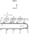
- FIG. 6 is a front view showing a state in which the workpiece W is conveyed by the chain conveyor 20. Note that a spinner roller 28, which will be described later, on the front side in the figure is omitted in FIG.
- a plurality of carriers 26 that support the workpiece W are attached to the outer peripheral surface of the chain 22.
- the carrier 26 has a rod-like body portion and is arranged at equal intervals along the longitudinal direction of the chain 22.
- the carrier 26 supports the end of the workpiece W from the upstream side in the transport direction when the chain 22 circulates, and continuously supports the workpiece W. It is designed to be transported.
- the chains 22 are provided in pairs on the left and right sides, and the carrier 26 is erected vertically on a chain plate 23 that spans the pair of left and right chains 22. ing.
- a pair of spinner rollers 28 composed of rotation rollers are disposed on the upper side of the chain 22 and on both sides of the carrier 26.
- the pair of spinner rollers 28 is disposed on both sides in the conveyance direction of the workpiece W, and the workpiece W is placed on the pair of spinner rollers 28.
- the chain conveyor 20 and the spinner roller 28 constitute a conveying means for conveying the workpiece W.
- a change adjustment mechanism 30 that changes and adjusts the distance between the spinner rollers 28 is provided at the shaft portions of the pair of spinner rollers 28.
- the change adjustment mechanism 30 includes a pair of rotating arms 30A disposed on both sides of the carrier 26, and the distal ends of the rotating arms 30A rotatably support the central axes of the pair of spinner rollers 28. ing.
- the base end portion of each rotation arm 30A is disposed in the proximity position of the carrier 26 and is fixed to the rotation shaft 30B.
- the rotary shaft 30B is rotatably supported on the apparatus frame side, and is connected to the shaft portion side of a drive motor 30D as a drive source via an endless belt 30C. .
- the change adjusting mechanism 30 rotates the rotating shaft 30B according to the rotation of the drive motor 30D, so that the rotating arm 30A pivots, and the shaft of the spinner roller 28 is rotated as shown in FIG. The part is displaced along the circular arc trajectory.
- a drive motor 29 is fixed to the distal end portion of the rotating arm 30A via a bracket 31, and the output shaft of the drive motor 29 is the shaft portion of the spinner roller 28. It is connected to.
- the spinner roller 28 can be driven to rotate about the central axis.
- the pair of spinner rollers 28 shown in FIG. 5B are driven to rotate in the same direction around the central axis.
- the pair of spinner rollers 28 preferably have the same diameter and are rotated at the same constant speed.
- position control of the workpiece W is important.
- the rotation mechanism of the spinner roller 28 and the conveyance mechanism of the workpiece W operate accurately.
- the rotation mechanism of the spinner roller 28 is preferably equipped with a rotation roller inverter for setting the number of rotations of the roller according to the finished quality, and high-precision and long-life parts are used for stable product conveyance. Equipped with a rotating roller inverter, it is possible (easy) to change the setting of the number of roller rotations according to the finished quality, and control linked to the conveyance speed is also possible.
- work uses a special chain for the chain 22 for the stable product conveyance, and equips it with the inverter in order to set the conveyance speed matched with finishing quality.
- the special chain one having a clearance and wear resistance is used in order to suppress biting of the projection material (shot).
- shots biting of the projection material
- a carry-out chute 32 is provided on the most downstream side in the conveyance direction of the workpiece W of the cabinet 12.
- the upper end of the carry-out chute 32 is disposed on the extension line of the spinner roller 28 and is inclined downward in a direction away from the cabinet 12 side. That is, the carry-out chute 32 is a member that guides the workpiece W, which is placed on the spinner roller 28 and transferred by the carrier 26 (see FIG. 6) of the chain conveyor 20, to the outside of the cabinet 12.
- a plurality of projectors 42 are attached above the conveyance path of the workpiece W in the cabinet body 14.
- the projector 42 is a centrifugal projector having a known structure, and applies a centrifugal force to the projecting material (shot) in the control cage by the rotation of an impeller (impeller) having a plurality of blades.
- the projectile is discharged through the opening window. That is, the projector 42 accelerates the projection material by centrifugal force and projects the projection material vertically downward or obliquely downward toward the workpiece W conveyed to the projection chamber 14A.
- a plurality of projectors 42 are arranged.
- the present invention may be configured with a single projector 42.
- shot projection management which is important for obtaining a stable peening effect.
- shot grain size management is also important. This point will be described later.
- the shot flow rate, impeller rotation speed, and projection pattern are important items.
- the shot flow rate it is preferable to provide a shot tank level meter and an impeller ammeter with a lower limit detection in order to stably project an appropriate amount of the projecting material.
- the shot tank level meter is a measuring instrument that is attached to a projection material hopper 48 to be described later and performs shot replenishment timing.
- the impeller ammeter with lower limit detection detects an insufficient amount of projection, displays an abnormal indication in the case of insufficient projection, stops the device, and prevents defective products that are insufficiently processed from flowing out of the device. It is a device.
- the impeller rotation speed in order to set the appropriate projection speed according to the finished quality and maintain the state, check the state (wear and elongation) of the V belt used for transmitting the driving force to the impeller, And an impeller inverter is preferred. By using the impeller inverter, it is possible (easy) to change the setting of the impeller rotational speed according to the finished quality.
- the projection pattern in order to project the projection material at an appropriate projection position with respect to the workpiece (workpiece), the control cage angle display (reference position display on the arrow name board) and impeller related consumables (blade, control cage) It is preferable to provide a function for notifying the replacement time of the distributor. About the latter, it is for preventing that a projection position and a projection amount change with wear of impeller related parts.
- a projection material introduction pipe 44 (also referred to as “introduction pipe”) is disposed above each projector 42.
- the upper end of the projection material introduction pipe 44 is connected to a projection material hopper 48 (shot tank) via a cut gate 46 (flow rate adjusting device).
- the projection material hopper 48 is a hopper for temporarily storing the projection material.
- the main portion 48A which is the internal space of the projection material hopper 48 of the present embodiment, is partitioned by a partition wall 48D on the upstream and downstream sides in the workpiece transport direction, and both sides in the direction orthogonal to the workpiece transport direction are partitioned by the side portions 48B and 48C. It has been.
- the cut gate 46 described above is connected to the bottom side of the main portion 48 ⁇ / b> A of the projection material hopper 48.
- the cut gate 46 is an open / close gate for adjusting the flow rate of the projection material supplied from the main portion 48 ⁇ / b> A of the projection material hopper 48.
- the first shot curtain device 36 is connected to the bottom side of the left side portion 48B of the projection material hopper 48 via a supply pipe 34A.
- the first shot curtain device 36 is disposed on the upper side of the projection chamber inlet 14 ⁇ / b> B and is fixed to the cabinet 12.
- the first shot curtain device 36 includes a container portion 36A connected to the supply pipe 34A and a downward rectangular pipe 36B connected to the bottom of the container portion 36A.
- the rectangular pipe 36 ⁇ / b> B is formed in a rectangular cylindrical shape and is used for causing the projection material to flow out.
- the inner space of the container portion 36A is partitioned into an upper space and a lower space by an upper partition plate.
- the first shot curtain device 36 is provided with a gate mechanism 36D that can open and close the opening of the upper partition plate. Further, a box-shaped receiving portion that opens upward is provided on the lower side of the opening portion of the upper partition plate inside the container portion 36A, and the receiving portion falls through the opening portion of the upper partition plate. The projection material is received once and then supplied downward.
- the first shot curtain device 36 configured in this manner causes the projection material supplied from the supply pipe 34A to continuously drop from the upper part of the projection chamber inlet 14B into a curtain shape through the rectangular pipe 36B via the container portion 36A. It is possible to generate a so-called shot curtain. That is, the projection chamber inlet 14B has a structure in which the shot curtain is opened and closed by opening and closing the gate of the gate mechanism 36D.
- a second shot curtain device 38 is connected to the bottom side of the right side portion 48C of the projection material hopper 48 via a supply pipe 34B.
- the second shot curtain device 38 is disposed on the upper side of the projection chamber outlet 14 ⁇ / b> C and is fixed to the cabinet 12.
- the second shot curtain device 38 includes a container portion 38A connected to the supply pipe 34B, and includes a downward rectangular pipe 38B connected to the bottom of the container portion 38A.
- the rectangular pipe 38B is formed in a rectangular cylindrical shape, and is used for outflow of the projection material.
- the inner space of the container portion 38A is partitioned into an upper space and a lower space by an upper partition plate.
- the second shot curtain device 38 is provided with a gate mechanism 38D that can open and close the opening of the upper partition plate.
- a box-shaped receiving portion that opens upward is provided below the opening portion of the upper partition plate, and the receiving portion falls through the opening portion of the upper partition plate. The projection material to be received is once received and then supplied downward.
- the second shot curtain device 38 configured in this way continuously drops the projection material supplied from the supply pipe 34B from the upper part of the projection chamber outlet 14C through the rectangular pipe 38B via the container portion 38A, It is possible to generate a so-called shot curtain. That is, the projection chamber outlet 14C has a structure in which the shot curtain is opened and closed by opening and closing the gate of the gate mechanism 38D.
- the projector 42 disposed between the first shot curtain device 36 and the second shot curtain device 38 on the cabinet 12 includes a projection material introduction pipe 44, a cut gate 46, and a main portion 48A of the projection material hopper 48. It is connected to the circulation device 50 via.
- the circulation device 50 is a device for conveying the projection material projected by the projector 42 and circulating it to the projector 42, and includes a lower screw conveyor 52 on the lower side of the chain conveyor 20 inside the cabinet 12. .
- the lower screw conveyor 52 is horizontally arranged with the conveying direction of the workpiece W as a longitudinal direction.
- the spiral winding direction of the screw blades of the lower screw conveyor 52 is reversed between the part disposed on the upstream side in the transport direction of the shot peening apparatus 10 and the part disposed on the downstream side in the transport direction of the shot peening apparatus 10. .
- the lower screw conveyor 52 rotates around the axis to convey the projected projection material and the like from the upstream and downstream sides in the conveyance direction of the shot peening apparatus 10 to the central portion side, and the projection material and the like at one location. So that it can be recovered.
- a central portion in the conveyance direction of the shot peening apparatus 10 of the lower screw conveyor 52 is disposed adjacent to a lower collection portion of the bucket elevator 54 (FIG. 2) where a projection material recovery path is disposed. And the bucket elevator 54 receives the projection material etc. which were conveyed by the lower screw conveyor 52 from the upstream and the downstream in the conveyance direction of the shot peening apparatus 10 to the center part side from the lower screw conveyor 52.
- the bucket elevator 54 Since the bucket elevator 54 has a known structure, a detailed description thereof is omitted. However, an endless belt 54B is wound around a pulley 54A disposed at the upper and lower portions of the shot peening apparatus 10, and a number of buckets are wound around the endless belt 54B. (Not shown) is attached.
- the pulley 54A is rotationally driven by a motor. Due to this rotational drive, the bucket elevator 54 falls to the lower part of the shot peening apparatus 10 and is collected by the lower screw conveyor 52 (a mixture containing the projection material projected on the workpiece W and powdered foreign matter). Is lifted by a bucket and conveyed from the lower part of the shot peening apparatus 10 to the upper part (above the cabinet 12).
- the lower screw conveyor 52, the bucket elevator 54, and the like constitute a projection material recovery mechanism.
- a distribution box 56 is disposed adjacent to the front side of the upper end of the bucket elevator 54 and is connected to the distribution box 56 through an upper carry-out port (a discharge port portion) of the bucket elevator 54. As shown in FIGS. 1 and 2, the distribution box 56 is supplied to the first route 40 ⁇ / b> A for supplying the projection material projected from the bucket of the bucket elevator 54 to the projector 42 and the first shot curtain device 36. The distribution is divided into a second route 40B for supply and a third route 40C for supply to the second shot curtain device 38.
- the first route 40 ⁇ / b> A is a route in which the projection material reaches the projector 42 from the distribution box 56 through the separator 60, the main portion 48 ⁇ / b> A of the projection material hopper 48, the cut gate 46, and the projection material introduction pipe 44.
- the second route 40B shown in FIG. 1 the projecting material passes through the distribution box 56, the distribution pipe 58A, the left side portion 48B of the projection material hopper 48, and the supply pipe 34A. This is the route to 36.
- the third route 40C is a route in which the projection material passes from the distribution box 56 to the second shot curtain device 38 through the distribution pipe 58B, the right side portion 48C of the projection material hopper 48, and the supply pipe 34B.
- the upper discharge side of the bucket elevator 54 is connected to the separator 60 (wind sorting mechanism 62) via the distribution box 56, and is connected to the separator 60 (wind sorting mechanism 62) via the distribution box 56.
- the first shot curtain device 36 (see FIG. 1) and the second shot curtain device 38 are not connected.
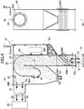
- FIG. 4 shows the configuration of a separator 60 (opposite classifier) having a wind sorting mechanism 62.
- 4A is a side sectional view of the separator 60 (a sectional view taken along line 4A-4A in FIG. 4B), and
- FIG. 4B is a front view of the separator 60.
- the separator 60 is provided in a collection path for collecting the projection material projected onto the workpiece W, and includes a settling chamber 68 that communicates with the intake side of the dust collector 80 as shown in FIG.
- a flange 68B for duct connection (see FIG. 4B) is formed on the upper side of the settling chamber 68.
- the dust collector 80 is for collecting foreign matter (impurities) such as fine powder mixed in the projection material, and includes a suction device (blower) for sucking air, and is settled via a suction duct 70 (separator duct). It is connected to the chamber part 68.
- a counter wind selector 66 is provided on the upstream side of the air flow of the settling chamber 68.
- a mesh-shaped screen 64A that divides the supply unit 64 into two upper and lower spaces is horizontally attached to the supply unit 64.
- the mesh of the screen 64A is set to a size that allows the projection material to pass through.
- An inclined portion 64B is formed below the screen 64A of the supply portion 64.
- the inclined portion 64B is provided on the upstream side of the flow path of the opposing wind selection unit 66, and inclines downward toward the opposing wind selection unit 66 (that is, obliquely downward).
- 66B) is a region in which the mixture of the projection material and the foreign matter supplied flows down.
- a regulation plate 64 ⁇ / b> C is provided at the most downstream portion of the supply unit 64 so as to close the upper side of the communication opening 65 with the opposing wind selection unit 66.
- the restricting plate 64C is a plate that extends in the separator width direction (direction perpendicular to the paper surface of FIG. 4A).
- the restricting plate 64C is suspended downward by fixing the upper end of the restricting plate 64C to the partition wall between the supply unit 64 and the counter wind selector 66 on the upper side of the communication opening 65, and the lower end edge and the inclined portion of the restricting plate 64C.
- the height position of the restricting plate 64C can be adjusted.
- the inclined portion 64B is provided on the upstream side of the flow path of the free fall zone 66B where the mixture freely falls, and the regulation plate 64C is a granular material that flows out from the supply portion 64 to the opposing wind selection portion 66 (mixture including a projection material).
- This layer has a function of sufficiently spreading and making it uniform in the separator width direction (direction perpendicular to the paper surface of FIG. 4A).
- the counter wind selector 66 includes a peripheral wall 66A that is formed in a cylindrical shape and extends in the vertical direction of the shot peening apparatus 10.
- the inner wall of the peripheral wall portion 66A is an air passage, and a gap formed between the lower end edge of the restricting plate 64C and the downstream end of the inclined portion 64B is opened as a communication port with the supply portion 64 in the longitudinal intermediate portion. is doing.
- an inner space of a portion below the communication portion with the supply portion 64 is a free fall zone 66B for allowing the mixture to fall freely.
- the lower end opening 66C of the peripheral wall 66A is an air inlet opening downward, and a mesh-like screen (not shown) is stretched horizontally on the outer peripheral side.
- a plurality of dispersing rods 66D are attached to the lower portion of the peripheral wall portion 66A so as to cross the free fall zone 66B.
- the dispersion rod 66D has a prismatic or cylindrical shape, and is disposed on the extended line of the inclined portion 64B at an interval so as to be positioned downward as it is separated from the inclined portion 64B.
- the dispersion rod 66D is configured to disperse the mixture of the projectile and the foreign material that freely falls in the free fall zone 66B in the free fall zone 66B.
- the mixture of the free-falling projection material and the foreign matter is dispersed by the dispersion rod 66D, so that an appropriate space is generated between the falling mixture, and the upward air flow f1 in the free-fall zone 66B falls. It flows almost uniformly between the mixtures. As a result, the upward airflow flows substantially uniformly between the free-falling projection material and the foreign matter, and the selection (classification) of the mixture by the upward airflow is facilitated.
- the spacing between the dispersing rods is set so that the projection material does not stay on the dispersing rod and does not disturb the air flow f1, and the spacing between the free-falling projection material and the foreign matter can be evenly dispersed.
- a concave (dish-shaped) receiving portion 72 is provided at a position opposed to the lower end opening 66C of the peripheral wall portion 66A.
- the receiving portion 72 is used for preventing wear of parts due to the projecting material.
- the receiving portion 72 temporarily receives the projecting material that freely falls and stops the dropping, and then the main portion 48A of the projecting material hopper 48 on the lower side (see FIG. 1). ).
- the counter wind selector 66 applies the upward air flow f1 to freely drop the mixture of the projection material and the particulate foreign matter, thereby dropping the lightweight object placed on the air flow f1 ( (Refer to the direction of arrow S1) Separated from heavy objects More specifically, the counter wind selection unit 66 selects “small and light particle size” (foreign matter) to be put on the air flow f1 and “falling large and heavy particle size” (projection material) that falls. .
- a guide plate 68A is disposed so as to hang down from the upper wall side.
- the guide plate 68A guides the air containing the particulate matter sucked into the settling chamber 68 by the suction input of the dust collector 80, and generates a bypass flow f2 as a classified flow to the air. That is, the settling chamber 68 separates (selects) the particles in the sucked air by the bypass flow f2.
- the settling chamber section 68 places lighter fine powder (powder) having a smaller particle size out of the sucked powder (foreign matter) on the airflow and discharges it to the dust collector 80 side (arrow) S3), a fine powder (granular material) having a larger particle size is dropped (arrow S2) and discharged to the roughing case 84 side via the roughing pipe 82 shown in FIG.
- the configuration of the classifier (separator 60) and the management of the amount of dust collected are the points.
- an opposed classifier is used as described above in order to maintain shot granularity. By using such an opposed classifier, it is possible to manage the granularity with higher accuracy (fineness) than the direct classifier.
- a differential pressure upper limit switch is installed in the dust collector 80 (see FIG. 3 and FIG. 4A), etc. It is preferable to display an abnormality when the required air volume is reduced.
- a consumables notification function is provided on the control panel 90A shown in FIG. 3 to display the replacement time of the consumables on the touch panel, and the consumable replacement history is displayed on the control panel 90A or the like. It is preferable to be able to grasp the replacement period.
- the consumables constituting the shot peening apparatus 10 include the consumables constituting the projector 42 shown in FIGS. 1 to 3, the consumables constituting the transport mechanism for transporting the workpiece W, and the circulation device 50.
- the consumables constituting the projector 42 include, for example, blades, control cages, distributors, and liner-related parts.
- the consumables constituting the transport mechanism for transporting the workpiece W include a spinner roller 28, a chain 22, a carrier 26, and a transport guide.
- the consumables constituting the circulation device 50 include, for example, a lower screw conveyor 52, an endless belt 54B of the bucket elevator 54, and a bucket of the bucket elevator 54.
- the control device 90 including the control panel 90 ⁇ / b> A includes a calculation unit 92.
- the calculation unit 92 is configured by a computer or the like, and compares the operation time tex (consumption time) with a preset life time tz for each consumable composing the shot peening apparatus 10 to determine each consumable product. Calculate the replacement time.
- the operation time tx is measured as a time equal to the projection time of the projector 42, and is integrated by sequencer control.
- the control panel 90A is provided with a display unit 94 (display), and the display unit 94 can display the calculation result of the calculation unit 92.
- the control device 90 causes the display unit 94 to display all or part of the calculation result of the calculation unit 92 according to the operation of the control panel 90A.
- the control device 90 may include a determination unit (not shown) for specifying a display target. For example, the determination unit compares the operation time tx with a standard time ta set in advance shorter than the life time tz for each consumable constituting the shot peening apparatus 10, and the operation time tx is the standard time. It is determined whether or not ta is exceeded. Then, the control device 90 controls the display unit 94 to display the replacement time only for the consumables for which the operating time tx is determined to exceed the standard time ta by the determining unit.
- the control device 90 includes a storage unit 96.
- the storage unit 96 information on the replacement history of each consumable constituting the shot peening apparatus 10 is input by the operator from the control panel 90A, for example.
- storage part 96 memorize
- the display unit 94 can display information on the exchange history stored in the storage unit 96. That is, for example, when an operation for requesting display of the replacement history information is performed on the control panel 90A, the replacement history information is displayed on the display unit 94.
- the storage unit 96 may store information on operation abnormality history that has occurred in the past, and the display unit 94 may display information on operation abnormality history stored in the storage unit 96.
- an operation abnormality history display function By having such an operation abnormality history display function, it is easy to grasp the frequency and tendency of occurrence of operation abnormality, and a serious trouble can be prevented in advance. Further, when elucidating the cause of an abnormal operation, the cause of the abnormal operation can be estimated to some extent from the history of occurrence of the abnormal operation. Therefore, having an operation abnormality history display function is useful for early recovery from an abnormal operation state.
- the projector 42 projects a projection material onto the workpiece W shown in FIG.
- a cylindrical workpiece such as a coil spring is processed.
- the wind path sorting mechanism 62 shown in FIG. 4 is provided in the collection path for collecting the projection material projected onto the workpiece W.
- the wind wind sorting mechanism 62 includes the projection material and powdered foreign matters. While allowing the mixture to fall freely, an upward air flow f1 is applied to the mixture, thereby selecting a lightweight object to be put on the air flow f1 and a heavy object to be dropped. In this way, the upward air flow f1 is applied to the free-falling mixture, so that sorting is performed with high accuracy. In addition, when the mixture contains a large amount of lightweight foreign substances, sorting is performed efficiently.
- the wind power sorting mechanism 62 is provided with an inclined portion 64B on the upstream side of the flow path of the free fall zone 66B where the mixture is freely dropped, and this inclined portion 64B is inclined obliquely downward to free fall of the mixture. It is intended for flow into zone 66B.
- the restricting plate 64C arranged so as to form a gap between the lower end of the inclined portion 64B allows the mixture to freely fall from the gap at the lower end portion of the inclined portion 64B.
- the mixture expands in the plate width direction of the restricting plate 64C while the flow rate to the free fall zone 66B is restricted by the restricting plate 64C, so that the mixture is easily selected by the upward air flow f1.
- the mixture that freely falls inside the peripheral wall portion 66A is dispersed by the plurality of dispersion rods 66D.
- the mixture is dispersed by the dispersion rod 66D, whereby the upward air flow f1 flows substantially uniformly, and as a result, the selection (classification) of the mixture by the air flow f1 is facilitated.
- a concave receiving portion 72 is provided on the lower side of the opposing wind selecting portion 66 of the wind sorting mechanism 62, and the projecting material that freely falls is once received by the receiving portion 72 and then the lower projecting material. It is supplied to the main part 48A (see FIG. 1) of the hopper 48. Thereby, the abrasion by the projection material of the components located below is suppressed.
- a settling chamber portion 68 that generates a bypass flow f2 by the guide plate 68A is provided on the downstream side of the flow passage of the lightweight object in the wind power sorting mechanism 62, and the lightweight object is the settling chamber section. 68 separates the powdery material placed in the detour flow f2 and the falling granular material. And a powdery material is discharged
- the particle size of the projection material supplied to the projector 42 can be stabilized. As a result, a stable peening effect can be obtained.
- the first shot curtain device 36 continuously drops the projection material from the upper part of the projection chamber inlet 14B, and the second shot curtain device 38 from the upper part of the projection chamber outlet 14C.
- the projectile is dropped continuously.
- the projection material projected by the projector 42 tries to jump out of the projection chamber inlet 14B and the projection chamber outlet 14C
- the projection material collides with the continuously falling projection material and is prevented from jumping out.
- the first shot curtain device 36 and the second shot curtain device 38 scattering of the projection material is prevented, so that the overall length of the device is shortened and the number of so-called rubber warmers installed is reduced. it can.
- the first shot curtain device 36 and the second shot curtain device 38 a portion that cannot be sealed by so-called rubber warming (for example, the coil spring in the case where the rubber warming is turned up with the passage of the coil spring as a workpiece). Since the inner side etc. can be sealed, the amount of projection material scattered outside the device is also reduced.
- rubber warming for example, the coil spring in the case where the rubber warming is turned up with the passage of the coil spring as a workpiece. Since the inner side etc. can be sealed, the amount of projection material scattered outside the device is also reduced.
- the projectile that has fallen to the lower part of the apparatus is conveyed to the upper part of the apparatus by a bucket elevator 54 provided in the recovery path.
- the upper discharge side of the bucket elevator 54 shown in FIGS. 1 and 2 is connected to the wind sorting mechanism 62, and the first shot curtain device 36 and the second shot curtain device are not connected via the wind sorting mechanism 62. 38 is also connected.
- the enlargement of the wind-power sorting mechanism 62 and the dust collector 80 (refer FIG. 3) is suppressed.
- the workpiece W is transported by being pushed in the transport direction by the carrier 26 when the chain 22 circulates.
- a pair of spinner rollers 28 arranged above the chain 22 and on both sides with respect to the carrier 26 are arranged side by side around the conveyance direction of the workpiece W and rotate around an axis extending in the conveyance direction. It can be driven and a workpiece W is placed thereon. For this reason, when the work W is placed on the pair of spinner rollers 28 and the spinner roller 28 rotates, when the work W is projected by the projector 42 (see FIG. 1), the work W is uniformly shot.
- the distance between the pair of spinner rollers 28 can be changed and adjusted by the change adjusting mechanism 30. For this reason, since the distance between the pair of spinner rollers 28 can be changed according to the size (diameter) of the workpiece W, the length of the carrier 26 in the vertical direction of the apparatus can be suppressed. That is, for example, when a large work W is placed on the pair of spinner rollers 28, if the distance between the pair of spinner rollers 28 is widened, the upper end height position of the work W can be kept low. It is also possible to suppress the length of the apparatus 26 in the vertical direction, and the overall height of the shot peening apparatus 10 can be suppressed. In addition, since the distance between the pair of spinner rollers 28 can be changed and adjusted, workpieces W having various outer diameters can be placed on the pair of spinner rollers 28. Can be processed.
- the shot peening apparatus 10 As described above, according to the shot peening apparatus 10 according to the present embodiment, it is possible to accurately separate the recovered projection material and the foreign matter while suppressing an increase in the size of the apparatus.
- the display unit 94 of the control panel 90A displays information on the replacement time and replacement history of each consumable constituting the shot peening apparatus 10, so that the consumable can be replaced with reference to this display.
- “conveyance trouble” means that the workpiece W is not conveyed normally (for example, due to insufficient rotation of the workpiece W or the workpiece W being caught), and the projection material is not evenly projected onto the workpiece W, and a stable shot peening effect. Is not obtained, or the work W is completely caught in the cabinet 12 and cannot be processed.
- the centrifugal projector 42 is used as the projector.
- the projector may be another projector such as an air nozzle projector that pumps the projection material together with the compressed air and injects it from the nozzle. It may be a projector.
- the shot processing apparatus is the shot peening apparatus 10, but the shot processing apparatus may be another shot processing apparatus such as a shot blasting apparatus. Moreover, you may use the apparatus of the same structure as the shot peening apparatus 10 as a shot peening apparatus and shot blasting apparatus.
- FIG. 4 (A) shows, although the wind-power selection mechanism 62 is provided with the inclination part 64B and the control board 64C, it can also be set as the structure which a wind-power selection mechanism does not provide these. It is.
- the upper end part of a control board is a separator width direction ( It may be another restricting plate that can be rotated around an axis in a direction perpendicular to the paper surface of FIG.
- the wind sorting mechanism 62 includes a plurality of dispersion bars 66D, but a configuration in which the wind sorting mechanism does not include a plurality of dispersion bars may be employed.
- the concave receiving part 72 is provided in the downward side of the opposing wind selection part 66 of the wind selection mechanism 62, such a receiving part is not provided in the downward side of a wind selection mechanism. Can also be taken.
- the settling chamber portion 68 is provided on the downstream side of the light-weight passage in the wind sorting mechanism 62.
- a configuration in which a substantially cylindrical cyclone portion is provided instead of the settling chamber portion 68, A configuration in which the settling chamber portion is not provided can also be adopted.
- the upper discharge side of the bucket elevator (54) as the shot conveying device is connected to the first shot curtain device (36) and the second shot curtain device (38) via the wind sorting mechanism (62).
- the structure connected to can also be taken.
- an axial direction is an apparatus up-down direction, for example.
- Other shot transport devices such as screw conveyors set in the direction may be used.
- the change adjustment mechanism 30 includes a rotation arm 30 ⁇ / b> A, and changes and adjusts the interval between the spinner rollers 28 as a pair of rotation rollers by rotational movement.
- the change adjustment mechanism may be, for example, another change adjustment mechanism that includes a pinion and a rack and changes and adjusts the distance between the pair of rotation rollers by linear movement. Further, a configuration in which the shot processing apparatus does not include a change adjustment mechanism is possible.
- a part of the bottom surface of the lower part of the apparatus may be set to have a height different from other parts of the bottom surface.
- the display unit 94 can display the calculation result of the calculation unit 92 and can display the replacement history information stored in the storage unit 96.
- the calculation unit (92) A display unit capable of displaying the calculation result and a display unit capable of displaying the information of the exchange history stored in the storage unit (96) may be provided separately.
- Shot peening equipment (shot processing equipment) 12 cabinet 14A projection chamber 14C projection chamber outlet 14B projection chamber inlet 20 chain conveyor 22 chain 26 attachment (pressing member) 28 Spinner roller (spinning roller) 30 Change Adjustment Mechanism 36 First Shot Curtain Device 38 Second Shot Curtain Device 42 Projector 54 Bucket Elevator (Shot Transport Device) 62 Wind sorting mechanism 64B Inclined portion 64C Restriction plate 66A Peripheral wall portion 66B Free fall zone 66D Dispersion rod 68 Settling chamber portion 68A Guide plate 72 Receiving portion 92 Calculation portion 94 Display portion 96 Storage portion f1 Upward air flow f2 Detour flow W Workpiece
Landscapes
- Engineering & Computer Science (AREA)
- Mechanical Engineering (AREA)
- Combined Means For Separation Of Solids (AREA)
- Disintegrating Or Milling (AREA)
- Filling Or Emptying Of Bunkers, Hoppers, And Tanks (AREA)
- Control Or Security For Electrophotography (AREA)
Abstract
Description
ワークに投射材を投射する投射機と、
前記投射機により投射された投射材を回収する回収機構と、
回収された投射材に上向きの気流をあてながら、前記回収された投射材を自由落下させ、前記回収された投射材に混入している異物を、前記回収された投射材から分離する風力選別機構と、を備えている、
ことを特徴とするショット処理装置が提供される。
これは、投射材と異物の混合物が気流にさらされる時間が長くなることにより選別精度が良くなるためである。
前記風力選別機構は、
前記上向きの気流が生成され、前記回収された投射材が自由落下させられる自由落下ゾーンと、
最下部が前記自由落下ゾーンと開口部を介して連通し、前記回収された投射材が供給される供給部と、を備え、
前記開口部は、前記供給部の自由落下ゾーン側に上下方向に延びるよう配置された規制板と、該規制板の下端と前記供給部の自由落下ゾーンに向かって斜め下方に傾斜して延びる傾斜部との間に形成されている。
前記風力選別機構は、
前記自由落下ゾーン内を横切って配置された複数の分散棒を備えている。
前記自由落下ゾーンの下方には、自由落下した投射材を受ける凹状の受部が設けられている。
前記風力選別機構は、前記自由落下ゾーンの上方に連通したセントリングチャンバー部を備え、
前記セントリングチャンバー部では、前記異物を、案内板によって迂回流を生じさせ、前記迂回流に乗せられる粉状物と落下する粒状物とに分離する。
前記投射材が投射される投射室が内部に形成され、前記ワークを前記投射室に搬入するための投射室入口と前記ワークを前記投射室から搬出する投射室出口をと備えたキャビネットと、
前記投射室入口の上部から投射材をカーテン状に落下させる第一ショットカーテン装置と、
前記投射室出口の上部から投射材をカーテン状に落下させる第二ショットカーテン装置と、
投射された投射材を前記投射室から回収する回収機構と、
前記回収機構によって回収された投射材を、前記風力選別機構と前記第一ショットカーテン装置と前記第二ショットカーテン装置とに分配する分配箱と、を備えている。
また、投射された投射材は、分配装置により風力選別機構と、第一ショットカーテン装置と、第二ショットカーテン装置とに分配されるため、風力選別機構に供給される投射材の量が適正化され、風力選別機構及び集塵機の大型化が抑えられる。
前記風力選別機構により異物が分離された投射材は、前記投射機に供給される。
前記投射機から投射材を投射される位置に前記ワークを搬送する搬送手段を備え、
前記搬送手段は、
回転駆動される無端のチェーンと、前記チェーンの外周側に取り付けられ前記ワークを支持するキャリアとを有するチェーンコンベアと、
前記キャリアの前記ワークの搬送方向両側に配置され、前記ワークの搬送方向に延びる軸線を中心に自転且つ揺動可能とされた一対の自転ローラと、を備えている。
前記一対の自転ローラの間隔を変更調整する変更調整機構が設けられている。
例えば、大きなワークを一対の自転ローラに載せる場合には一対の自転ローラの間隔を広げれば、ワークの上端高さ位置を低く抑えることができるので、ワークを支持するキャリアの上下方向の長さを抑えることも可能になり、装置全体の高さが抑えられる。
また、一対の自転ローラの間隔が変更調整可能となることで、様々な外径のワークを一対の自転ローラ上に載せることができるので、様々な外径のワークに対してショット処理をすることができる。
ショット処理装置の底面はフラットに形成されている。
前記ショット処理装置に備えられた消耗品の稼働時間と、予め設定された寿命時間とを比較し、前記消耗品の交換時期を計算する計算部と、前記計算部の計算結果を表示可能な表示部とを有する制御装置を備えている。
前記ショット処理装置に備えられた消耗品の交換履歴の情報が入力され該交換履歴の情報を記憶する記憶部と、前記記憶部で記憶された前記交換履歴の情報を表示可能な表示部とを有する制御装置を備えている。
また、上流側ブース16には、ワークWを搬入するための上流側ブース入口(図示省略)が、キャビネット本体14の投射室入口14Bに対向して形成されている。さらに、上流側ブース16に対して、ワークWの搬送方向のさらに上流側(図中左側)には、ショットピーニング装置10にワークWをセットするためセット部15が設けられている。なお、ワークWが重い、又は高温である等の手作業が困難となる場合には、セット部15にマニピュレータ、ハンドリング装置等の搬入装置(図示省略)を設け、この搬入装置からワークWを機械的に投入してもよい。
また、下流側ブース18には、ワークWを搬出するための下流側ブース出口(図示省略)がキャビネット本体14の投射室出口14Cに対向して形成されている。
図5(A)に示されるように、回転軸30Bは、装置フレーム側に回転可能に支持されると共に、無端ベルト30Cを介して駆動源である駆動モータ30Dの軸部側に接続されている。すなわち、変更調整機構30は、駆動モータ30Dの回転に応じて回転軸30Bが回転することで、回動アーム30Aが枢動し、図5(B)に示されるように、スピナーローラ28の軸部を円弧軌道に沿って変位させるようになっている。
スピナーローラ28の自転機構では、仕上り品質に合わせたローラ回転数を設定するために自転ローラインバータを装備し、及び安定した製品搬送用として高精度・高寿命部品を使用することが好ましい。自転ローラインバータを装備することで、仕上り品質に応じたローラ回転数の設定変更が可能(容易)となり、搬送速度とリンクした制御も可能となる。また、スピナーローラ28に高精度・高寿命部品を用いることで早期偏摩耗による搬送不良が防止、又は効果的に抑制され、最小の段差で引っ掛かりが少なくなる。
また、ワークWの搬送機構は、安定した製品搬送のためにチェーン22に特殊チェーンを用い、及び、仕上り品質に合わせた搬送速度を設定するためにインバータを装備するのが好ましい。
特殊チェーンとしては、投射材(ショット)の噛み込みを抑制するため、クリアランスがあって耐摩耗性を有するものが使用される。このような特殊チェーンを用いることで、ワークWの搬送機構の寿命が延びて搬送トラブルも防止又は効果的に抑制できる。また、インバータを装備することで、仕上り品質に応じた搬送速度の設定変更が可能(容易)になり、自転回転数とリンクした制御も可能となる。
すなわち、投射機42は、投射材を遠心力で加速して、投射室14Aに搬送されたワークWに向けて鉛直下方に又は斜め下方に投射するようになっている。なお、本実施形態では、投射機42が複数台配置されているが、本発明は、投射機42が一台である構成でもよい。
ショット流量については、適正量の投射材を安定的に投射するために、ショットタンクレベル計、及び、下限検知付きインペラ電流計を設けるのが好ましい。ショットタンクレベル計は、後述する投射材ホッパ48に取り付けられ、ショット補給タイミングをする計量器である。
下限検知付きインペラ電流計は、投射量不足を検知し、投射不足の場合には、異常表示を行い、さらに装置を停止させ、処理が不十分な不良品が装置から流出することを防止するための装置である。
インペラ回転数については、仕上り品質に合わせた適正投射速度の設定、及び、その状態の維持をなすために、インペラへの駆動力伝達用とされたVベルトの状態(摩耗や伸び)の点検、及びインペラインバータの装備が好ましい。インペラインバータを用いることで、仕上り品質に応じたインペラ回転数の設定変更が可能(容易)となる。
投射パターンについては、ワーク(ワーク)に対し適正な投射位置で投射材を投射するために、コントロールケージ角度の表示(矢印名盤で基準位置表示)、及びインペラ関係の消耗品(ブレード、コントロールケージ、ディストリビュータ等)についての交換時期を知らせる機能を設けるのが好ましい。後者については、インペラ関係部品の摩耗によって投射位置・投射量が変化するのを防止するためである。
投射材ホッパ48のメイン部48Aの底部側に、前述したカットゲート46が接続されている。なお、カットゲート46は、投射材ホッパ48のメイン部48Aから供給される投射材の流量を調整するための開閉ゲートである。
下部スクリューコンベヤ52のショットピーニング装置10の搬送方向中央部は、投射材の回収経路の配置されたバケットエレベータ54(図2)の下部収集部に隣接して配置されている。そして、バケットエレベータ54は、下部スクリューコンベヤ52によってショットピーニング装置10の搬送方向上流および下流側から中央部側に搬送されてきた投射材等を下部スクリューコンベヤ52から受けることになる。
プーリ54Aは、モータによって回転駆動される。この回転駆動により、バケットエレベータ54は、ショットピーニング装置10の下部に落下して下部スクリューコンベヤ52で回収された投射材等(ワークWに投射された投射材と粉粒状の異物とを含む混合物)をバケットで掬い上げ、ショットピーニング装置10の下部から上部(キャビネット12の上方側)へ搬送するようになっている。
本実施態様では、下部スクリューコンベヤ52、バケットエレベータ54等によって、投射材の回収機構が構成されている。
図1及び図2に示されるように、分配箱56は、バケットエレベータ54のバケットから投射された投射材を、投射機42に供給するための第一ルート40Aと、第一ショットカーテン装置36に供給するための第二ルート40Bと、第二ショットカーテン装置38に供給するための第三ルート40Cとに分配する。
また、図1に示されている第二ルート40Bは、投射材が、分配箱56から分配パイプ58A、投射材ホッパ48の左側のサイド部48B、及び供給パイプ34Aを通って第一ショットカーテン装置36に至るルートである。
さらに、第三ルート40Cは、投射材が分配箱56から分配パイプ58B、投射材ホッパ48の右側のサイド部48C、及び供給パイプ34Bを通って第二ショットカーテン装置38に至るルートである。
なお、集塵機80は、投射材に混入した微粉などの異物(不純物)を回収するためのものであり、空気を吸入する吸入装置(ブロワ)を備え、吸引ダクト70(セパレータダクト)を介してセトリングチャンバー部68に接続されている。セトリングチャンバー部68の気流上流側には、対向風選部66が設けられている。また、対向風選部66のセトリングチャンバー部68側と反対側の側方には、バケットエレベータ54の上部搬出口から搬出された投射材等を対向風選部66へ供給するための供給部64が設けられている。
傾斜部64Bは、混合物を自由落下させる自由落下ゾーン66Bの流路上流側に設けられ、規制板64Cは、供給部64から対向風選部66へ流出する粉粒物(投射材を含む混合物)の層をセパレータ幅方向(図4(A)の紙面に垂直な方向)に十分に広げて均一にする機能を有する。
周壁部66Aにおいて供給部64との連通部よりも下方側の部位の内側空間は、混合物を自由落下させるための自由落下ゾーン66Bとされている。
周壁部66Aの下端開口部66Cは、下向きに開口したエア導入口とされ、その外周側には、図示しないメッシュ状のスクリーンが水平に張られている。このため、自由落下ゾーン66Bでは、集塵機80が作動すると、スクリーンを通過した外気が周壁部66Aの下端開口部66Cから流入して周壁部66Aを通る上向きの気流f1が生じる。
分散棒の間隔は、分散棒上で投射材が滞留させず、気流f1を妨げないような広さであり、且つ自由落下する投射材と異物をムラなく分散できる間隔に設定されている。
より具体的には、対向風選部66は、気流f1に乗せられる「粒径が小さく軽いもの」(異物)と落下する「粒径が大きく重いもの」(投射材)とを選別している。
すなわち、セトリングチャンバー部68は、吸入された空気中の粒子を迂回流f2によって分離(選別)するようになっている。より具体的には、セトリングチャンバー部68は、吸入された粉粒物(異物)のうち、より粒径が小さく軽い微粉(粉状物)等を気流に乗せて集塵機80側へ排出し(矢印S3)、より粒径が大きく重い微粉(粒状物)等を落下させ(矢印S2)、図2に示される粗出しパイプ82を介して粗出ケース84側へ排出するようになっている。
投射機42を構成する各消耗品には、例えば、ブレード、コントロールケージ、ディストリビュータ、及びライナ関係の部品がある。ワークWを搬送するための搬送機構を構成する各消耗品には、例えば、スピナーローラ28、チェーン22、キャリア26、及び搬送ガイドがある。循環装置50を構成する各消耗品には、例えば、下部スクリューコンベヤ52、バケットエレベータ54の無端ベルト54B、及びバケットエレベータ54のバケットがある。
ワークWに投射された投射材を回収するための回収経路には、図4に示される風力選別機構62が設けられており、この風力選別機構62は、投射材と粉粒状の異物とを含む混合物を自由落下させながら、混合物に上向きの気流f1を当てることで、気流f1に乗せられる軽量物と落下する重量物とに選別する。このように自由落下する混合物に対して上向きの気流f1が当てられることで、選別が精度良くなされる。また、混合物に軽量の異物が大量に含まれている場合に選別が効率良くなされる。
傾斜部64Bの下端との間に隙間を形成するように配置された規制板64Cは、傾斜部64Bの下端部の隙間から混合物を自由落下させる。これにより、混合物は、自由落下ゾーン66Bへの流量が規制板64Cによって規制されつつ規制板64Cの板幅方向に広げられて自由落下するので、上向きの気流f1による混合物の選別が容易になる。
このように、第一ショットカーテン装置36及び第二ショットカーテン装置38が採用されることで、投射材の飛散が防止されるので装置の全長が短縮されると共に、所謂ゴム暖簾の設置枚数を低減できる。また、第一ショットカーテン装置36及び第二ショットカーテン装置38では、所謂ゴム暖簾でシールすることができない部分(例えば、ワークであるコイルばねの通過に伴ってゴム暖簾がめくれた場合におけるコイルばねの内側等)をシールできるため、投射材の装置外への飛散量も低減する。
なお、「搬送トラブル」とは、正常にワークWが搬送されないことで(例えば、ワークWの回転不足やワークWの引っ掛りにより)ワークWに投射材が均一に投射されず安定したショットピーニング効果が得られない、又は、ワークWがキャビネット12内で完全に引っ掛って処理できないことを意味する。
12 キャビネット
14A 投射室
14C 投射室出口
14B 投射室入口
20 チェーンコンベア
22 チェーン
26 アタッチメント(押圧部材)
28 スピナーローラ(自転ローラ)
30 変更調整機構
36 第一ショットカーテン装置
38 第二ショットカーテン装置
42 投射機
54 バケットエレベータ(ショット搬送装置)
62 風力選別機構
64B 傾斜部
64C 規制板
66A 周壁部
66B 自由落下ゾーン
66D 分散棒
68 セトリングチャンバー部
68A 案内板
72 受部
92 計算部
94 表示部
96 記憶部
f1 上向きの気流
f2 迂回流
W ワーク
Claims (12)
- ワークに投射材を投射する投射機と、
前記投射機により投射された投射材を回収する回収機構と、
回収された投射材に上向きの気流をあてながら、前記回収された投射材を自由落下させ、前記回収された投射材に混入している異物を、前記回収された投射材から分離する風力選別機構と、を備えている、
ことを特徴とするショット処理装置。 - 前記風力選別機構は、
前記上向きの気流が生成され、前記回収された投射材が自由落下させられる自由落下ゾーンと、
最下部が前記自由落下ゾーンと開口部を介して連通し、前記回収された投射材が供給される供給部と、を備え、
前記開口部は、前記供給部の自由落下ゾーン側に上下方向に延びるよう配置された規制板と、該規制板の下端と前記供給部の自由落下ゾーンに向かって斜め下方に傾斜して延びる傾斜部との間に形成されている、
請求項1記載のショット処理装置。 - 前記風力選別機構は、
前記自由落下ゾーン内を横切って配置された複数の分散棒を備えている、
請求項2記載のショット処理装置。 - 前記自由落下ゾーンの下方には、自由落下した投射材を受ける凹状の受部が設けられている、
請求項2又は3に記載のショット処理装置。 - 前記風力選別機構は、前記自由落下ゾーンの上方に連通したセントリングチャンバー部を備え、
前記セントリングチャンバー部では、前記異物を、案内板によって迂回流を生じさせ、前記迂回流に乗せられる粉状物と落下する粒状物とに分離する、
請求項2又は3に記載のショット処理装置。 - 前記投射材が投射される投射室が内部に形成され、前記ワークを前記投射室に搬入するための投射室入口と前記ワークを前記投射室から搬出する投射室出口をと備えたキャビネットと、
前記投射室入口の上部から投射材をカーテン状に落下させる第一ショットカーテン装置と、
前記投射室出口の上部から投射材をカーテン状に落下させる第二ショットカーテン装置と、
投射された投射材を前記投射室から回収する回収機構と、
前記回収機構によって回収された投射材を、前記風力選別機構と前記第一ショットカーテン装置と前記第二ショットカーテン装置とに分配する分配箱と、を備えている、
請求項2又は3に記載のショット処理装置。 - 前記風力選別機構により異物が分離された投射材は、前記投射機に供給される、
請求項2又は3に記載のショット処理装置。 - 前記投射機から投射材を投射される位置に前記ワークを搬送する搬送手段を備え、
前記搬送手段は、
回転駆動される無端のチェーンと、前記チェーンの外周側に取り付けられ前記ワークを支持するキャリアとを有するチェーンコンベアと、
前記キャリアの前記ワークの搬送方向両側に配置され、前記ワークの搬送方向に延びる軸線を中心に自転且つ揺動可能とされた一対の自転ローラと、を備えている、
請求項1から3のいずれか1項に記載のショット処理装置。 - 前記一対の自転ローラの間隔を変更調整する変更調整機構が設けられている、
請求項8に記載のショット処理装置。 - ショット処理装置の底面はフラットに形成されている、
請求項1から3のいずれか1項に記載のショット処理装置。 - 前記ショット処理装置に備えられた消耗品の稼働時間と、予め設定された寿命時間とを比較し、前記消耗品の交換時期を計算する計算部と、前記計算部の計算結果を表示可能な表示部とを有する制御装置を備えている、
請求項1から3のいずれか1項に記載のショット処理装置。 - 前記ショット処理装置に備えられた消耗品の交換履歴の情報が入力され該交換履歴の情報を記憶する記憶部と、前記記憶部で記憶された前記交換履歴の情報を表示可能な表示部とを有する制御装置を備えている、
請求項1から3のいずれか1項に記載のショット処理装置。
Priority Applications (5)
| Application Number | Priority Date | Filing Date | Title |
|---|---|---|---|
| JP2014521187A JP6016201B2 (ja) | 2012-06-12 | 2012-07-27 | ショット処理装置 |
| EP12878768.6A EP2862674B1 (en) | 2012-06-12 | 2012-07-27 | Shot processing machine |
| US14/407,386 US9884407B2 (en) | 2012-06-12 | 2012-07-27 | Shot processing machine |
| KR1020147028020A KR101652617B1 (ko) | 2012-06-12 | 2012-07-27 | 쇼트 처리 장치 |
| CN201280000933.XA CN103702799B (zh) | 2012-06-12 | 2012-07-27 | 喷丸处理装置 |
Applications Claiming Priority (2)
| Application Number | Priority Date | Filing Date | Title |
|---|---|---|---|
| JP2012-132821 | 2012-06-12 | ||
| JP2012132821 | 2012-06-12 |
Publications (1)
| Publication Number | Publication Date |
|---|---|
| WO2013186939A1 true WO2013186939A1 (ja) | 2013-12-19 |
Family
ID=49757798
Family Applications (1)
| Application Number | Title | Priority Date | Filing Date |
|---|---|---|---|
| PCT/JP2012/069177 Ceased WO2013186939A1 (ja) | 2012-06-12 | 2012-07-27 | ショット処理装置 |
Country Status (7)
| Country | Link |
|---|---|
| US (1) | US9884407B2 (ja) |
| EP (1) | EP2862674B1 (ja) |
| JP (1) | JP6016201B2 (ja) |
| KR (1) | KR101652617B1 (ja) |
| CN (1) | CN103702799B (ja) |
| TW (1) | TWI579107B (ja) |
| WO (1) | WO2013186939A1 (ja) |
Cited By (4)
| Publication number | Priority date | Publication date | Assignee | Title |
|---|---|---|---|---|
| WO2016009805A1 (ja) * | 2014-07-15 | 2016-01-21 | 新東工業株式会社 | ショット処理装置 |
| JP2020127979A (ja) * | 2019-02-08 | 2020-08-27 | 新東工業株式会社 | 異物除去装置及び異物除去装置を備えたブラスト加工装置 |
| JP2023051290A (ja) * | 2021-09-30 | 2023-04-11 | 新東工業株式会社 | ショットブラスト装置、検査方法、検査プログラム |
| JP2023080985A (ja) * | 2021-11-30 | 2023-06-09 | 新東工業株式会社 | 通知装置及び通知方法 |
Families Citing this family (15)
| Publication number | Priority date | Publication date | Assignee | Title |
|---|---|---|---|---|
| JP6304957B2 (ja) * | 2013-07-10 | 2018-04-04 | 中央発條株式会社 | ショットピーニング装置 |
| JP6161586B2 (ja) * | 2014-10-02 | 2017-07-12 | コトブキ技研工業株式会社 | 粒状物質の磨砕装置 |
| CZ2015437A3 (cs) * | 2015-06-25 | 2017-04-19 | PTV, spol. s r.o. | Sušící komora, sušící jednotka, sušička recyklátu a způsob sušení mokrého abraziva |
| CN105945734A (zh) * | 2016-07-14 | 2016-09-21 | 山东钢铁股份有限公司 | 一种抛丸机装置 |
| DE112018003242T5 (de) * | 2017-09-27 | 2020-04-09 | Sintokogio, Ltd. | Vorrichtung und Verfahren zur Oberflächenbehandlung |
| CN108406617A (zh) * | 2018-03-05 | 2018-08-17 | 重庆市梁平区宏富贵农机设备制造有限公司 | 抛丸机磨料回收系统 |
| US11475422B2 (en) | 2018-03-28 | 2022-10-18 | Bank Of America Corporation | Blockchain-based property management |
| US11295402B2 (en) | 2018-03-28 | 2022-04-05 | Bank Of America Corporation | Blockchain-based property repair |
| US10498808B2 (en) | 2018-03-28 | 2019-12-03 | Bank Of America Corporation | Blockchain-based property management |
| CN110802523B (zh) * | 2019-11-14 | 2021-08-31 | 常州优越喷丸加工有限公司 | 一种金属表面喷丸硬化方法 |
| CN111617878B (zh) * | 2020-05-12 | 2021-11-16 | 路德环境科技股份有限公司 | 一种适用于连续流化床烘干过程的除杂装置 |
| JP7273872B2 (ja) | 2021-02-10 | 2023-05-15 | 本田技研工業株式会社 | ショットピーニング装置 |
| CN113088650B (zh) * | 2021-04-09 | 2022-10-28 | 浙江冠林机械有限公司 | 一种用于环链表面处理的离心式抛丸机 |
| US12359742B2 (en) | 2022-10-24 | 2025-07-15 | Electronics Inc. | Controlling shot peening device via magnetic arrangement |
| CN117140366B (zh) * | 2023-10-11 | 2026-01-09 | 山东开泰抛丸机械股份有限公司 | 钢管输送装置和喷砂清理机 |
Citations (11)
| Publication number | Priority date | Publication date | Assignee | Title |
|---|---|---|---|---|
| JPS5423062A (en) * | 1977-07-25 | 1979-02-21 | Nhk Spring Co Ltd | Method and apparatus for processing shot peening and like |
| JPH0417054U (ja) * | 1990-06-01 | 1992-02-12 | ||
| JPH0957616A (ja) * | 1995-08-16 | 1997-03-04 | Kaedeoka Kogyo Kk | ばね研削機 |
| JPH107324A (ja) * | 1996-06-19 | 1998-01-13 | Toray Eng Co Ltd | 糸条の巻取方法 |
| JPH1128644A (ja) * | 1997-07-09 | 1999-02-02 | Ogihara:Kk | 切削機械の管理方法及びその装置 |
| JP2000042925A (ja) * | 1998-07-28 | 2000-02-15 | Sintokogio Ltd | ショット・砂分離装置 |
| JP2001038628A (ja) * | 1999-07-30 | 2001-02-13 | Nkk Corp | ビルトアップロンジ材の研掃装置 |
| JP2003334761A (ja) * | 2002-05-14 | 2003-11-25 | Toshiba Eng Co Ltd | 表面加工装置 |
| JP2011079094A (ja) * | 2009-10-07 | 2011-04-21 | Sintokogio Ltd | 連続式のコンベア式ショットピーニング装置及びショットピーニング方法 |
| CN102189496A (zh) | 2011-04-16 | 2011-09-21 | 无锡国达机械设备有限公司 | 节能型弹簧强化抛丸机 |
| JP2012020359A (ja) * | 2010-07-13 | 2012-02-02 | Kowa Dennetsu Keiki:Kk | 切削工具および切削加工評価装置 |
Family Cites Families (7)
| Publication number | Priority date | Publication date | Assignee | Title |
|---|---|---|---|---|
| GB663483A (en) | 1948-06-09 | 1951-12-19 | Svenska Flaektfabriken Ab | Method and arrangement for separating dust from a medium |
| US5782677A (en) * | 1997-01-14 | 1998-07-21 | Kanouse; Richard C. | Continuous process blast mill for finishing cast metal parts |
| IT1289890B1 (it) | 1997-01-15 | 1998-10-19 | Pan Chemicals S P A | Macchina granigliatrice per pulire una vergella metallica |
| JP2001252872A (ja) * | 2000-03-08 | 2001-09-18 | Sinto Brator Co Ltd | 投射材の定量供給装置 |
| WO2005110680A1 (ja) * | 2004-05-19 | 2005-11-24 | Sintokogio, Ltd. | 投射処理装置 |
| US20100211419A1 (en) * | 2009-02-13 | 2010-08-19 | Rearden Commerce, Inc. | Systems and Methods to Present Travel Options |
| KR102189496B1 (ko) | 2018-10-16 | 2020-12-11 | 민병옥 | 벽체 배수판 설치용 조립식 프레임 시스템 |
-
2012
- 2012-07-27 WO PCT/JP2012/069177 patent/WO2013186939A1/ja not_active Ceased
- 2012-07-27 KR KR1020147028020A patent/KR101652617B1/ko active Active
- 2012-07-27 US US14/407,386 patent/US9884407B2/en active Active
- 2012-07-27 JP JP2014521187A patent/JP6016201B2/ja active Active
- 2012-07-27 CN CN201280000933.XA patent/CN103702799B/zh active Active
- 2012-07-27 EP EP12878768.6A patent/EP2862674B1/en active Active
- 2012-08-09 TW TW101128732A patent/TWI579107B/zh active
Patent Citations (11)
| Publication number | Priority date | Publication date | Assignee | Title |
|---|---|---|---|---|
| JPS5423062A (en) * | 1977-07-25 | 1979-02-21 | Nhk Spring Co Ltd | Method and apparatus for processing shot peening and like |
| JPH0417054U (ja) * | 1990-06-01 | 1992-02-12 | ||
| JPH0957616A (ja) * | 1995-08-16 | 1997-03-04 | Kaedeoka Kogyo Kk | ばね研削機 |
| JPH107324A (ja) * | 1996-06-19 | 1998-01-13 | Toray Eng Co Ltd | 糸条の巻取方法 |
| JPH1128644A (ja) * | 1997-07-09 | 1999-02-02 | Ogihara:Kk | 切削機械の管理方法及びその装置 |
| JP2000042925A (ja) * | 1998-07-28 | 2000-02-15 | Sintokogio Ltd | ショット・砂分離装置 |
| JP2001038628A (ja) * | 1999-07-30 | 2001-02-13 | Nkk Corp | ビルトアップロンジ材の研掃装置 |
| JP2003334761A (ja) * | 2002-05-14 | 2003-11-25 | Toshiba Eng Co Ltd | 表面加工装置 |
| JP2011079094A (ja) * | 2009-10-07 | 2011-04-21 | Sintokogio Ltd | 連続式のコンベア式ショットピーニング装置及びショットピーニング方法 |
| JP2012020359A (ja) * | 2010-07-13 | 2012-02-02 | Kowa Dennetsu Keiki:Kk | 切削工具および切削加工評価装置 |
| CN102189496A (zh) | 2011-04-16 | 2011-09-21 | 无锡国达机械设备有限公司 | 节能型弹簧强化抛丸机 |
Cited By (9)
| Publication number | Priority date | Publication date | Assignee | Title |
|---|---|---|---|---|
| WO2016009805A1 (ja) * | 2014-07-15 | 2016-01-21 | 新東工業株式会社 | ショット処理装置 |
| JPWO2016009805A1 (ja) * | 2014-07-15 | 2017-04-27 | 新東工業株式会社 | ショット処理装置 |
| US10010998B2 (en) | 2014-07-15 | 2018-07-03 | Sintokogio, Ltd. | Shot processing apparatus |
| JP2020127979A (ja) * | 2019-02-08 | 2020-08-27 | 新東工業株式会社 | 異物除去装置及び異物除去装置を備えたブラスト加工装置 |
| JP7146172B2 (ja) | 2019-02-08 | 2022-10-04 | 新東工業株式会社 | 異物除去装置及び異物除去装置を備えたブラスト加工装置 |
| JP2023051290A (ja) * | 2021-09-30 | 2023-04-11 | 新東工業株式会社 | ショットブラスト装置、検査方法、検査プログラム |
| JP7722109B2 (ja) | 2021-09-30 | 2025-08-13 | 新東工業株式会社 | ショットブラスト装置、検査方法、検査プログラム |
| JP2023080985A (ja) * | 2021-11-30 | 2023-06-09 | 新東工業株式会社 | 通知装置及び通知方法 |
| JP7757739B2 (ja) | 2021-11-30 | 2025-10-22 | 新東工業株式会社 | 通知装置及び通知方法 |
Also Published As
| Publication number | Publication date |
|---|---|
| JPWO2013186939A1 (ja) | 2016-02-01 |
| US9884407B2 (en) | 2018-02-06 |
| TWI579107B (zh) | 2017-04-21 |
| EP2862674A1 (en) | 2015-04-22 |
| EP2862674B1 (en) | 2019-11-06 |
| JP6016201B2 (ja) | 2016-10-26 |
| CN103702799A (zh) | 2014-04-02 |
| TW201350269A (zh) | 2013-12-16 |
| US20150290770A1 (en) | 2015-10-15 |
| KR101652617B1 (ko) | 2016-08-30 |
| CN103702799B (zh) | 2016-09-21 |
| EP2862674A4 (en) | 2016-05-04 |
| KR20140130552A (ko) | 2014-11-10 |
Similar Documents
| Publication | Publication Date | Title |
|---|---|---|
| JP6016201B2 (ja) | ショット処理装置 | |
| US20190143373A1 (en) | Separator device and shot processing apparatus | |
| US7832243B2 (en) | Apparatus for a shot peening treatment | |
| TWI609744B (zh) | 珠擊裝置 | |
| EP2636486B1 (en) | A shot-processing apparatus | |
| CN203792183U (zh) | 抛丸处理装置 | |
| BR112019019279B1 (pt) | Dispositivo de tratamento com granalha | |
| CN114378725A (zh) | 筛选装置 | |
| WO2012111237A1 (ja) | 投射材分別装置およびショット処理装置 | |
| KR102504509B1 (ko) | 과일 크기별 안정적 이송이 가능한 과일 선별장치 | |
| JP7100405B1 (ja) | 粉体供給装置 | |
| KR100646754B1 (ko) | 석재의 표면가공을 위한 쇼트 블라스트 장치 | |
| JP6439993B2 (ja) | ショット処理装置 | |
| JP5720444B2 (ja) | ショット処理装置 | |
| US20230075301A1 (en) | Shot Peening Apparatus | |
| RU2630517C2 (ru) | Устройство и способ разделения загружаемого материала, по меньшей мере, на легкую фракцию материала и на тяжелую фракцию материала | |
| CN108136444B (zh) | 物体的筛选装置及其方法 | |
| CN103221181B (zh) | 喷射材料分离装置及喷射处理装置 | |
| CN103492125B (zh) | 喷丸处理装置 | |
| JP3126431B2 (ja) | 不定形物定量供給装置 | |
| JPS6238244B2 (ja) | ||
| JPH0915027A (ja) | 組合せ計量装置及びその装置を備えた組合せ計量システム並びに組合せ計量方法 |
Legal Events
| Date | Code | Title | Description |
|---|---|---|---|
| 121 | Ep: the epo has been informed by wipo that ep was designated in this application |
Ref document number: 12878768 Country of ref document: EP Kind code of ref document: A1 |
|
| ENP | Entry into the national phase |
Ref document number: 2014521187 Country of ref document: JP Kind code of ref document: A |
|
| ENP | Entry into the national phase |
Ref document number: 20147028020 Country of ref document: KR Kind code of ref document: A |
|
| WWE | Wipo information: entry into national phase |
Ref document number: IDP00201406130 Country of ref document: ID |
|
| NENP | Non-entry into the national phase |
Ref country code: DE |
|
| WWE | Wipo information: entry into national phase |
Ref document number: 14407386 Country of ref document: US |