WO2013186962A1 - Dispositif de traitement vidéo, dispositif d'imagerie et programme - Google Patents
Dispositif de traitement vidéo, dispositif d'imagerie et programme Download PDFInfo
- Publication number
- WO2013186962A1 WO2013186962A1 PCT/JP2013/001069 JP2013001069W WO2013186962A1 WO 2013186962 A1 WO2013186962 A1 WO 2013186962A1 JP 2013001069 W JP2013001069 W JP 2013001069W WO 2013186962 A1 WO2013186962 A1 WO 2013186962A1
- Authority
- WO
- WIPO (PCT)
- Prior art keywords
- video
- unit
- scenes
- digest
- information
- Prior art date
- Legal status (The legal status is an assumption and is not a legal conclusion. Google has not performed a legal analysis and makes no representation as to the accuracy of the status listed.)
- Ceased
Links
Images










Classifications
-
- H—ELECTRICITY
- H04—ELECTRIC COMMUNICATION TECHNIQUE
- H04N—PICTORIAL COMMUNICATION, e.g. TELEVISION
- H04N5/00—Details of television systems
- H04N5/76—Television signal recording
- H04N5/765—Interface circuits between an apparatus for recording and another apparatus
- H04N5/77—Interface circuits between an apparatus for recording and another apparatus between a recording apparatus and a television camera
- H04N5/772—Interface circuits between an apparatus for recording and another apparatus between a recording apparatus and a television camera the recording apparatus and the television camera being placed in the same enclosure
-
- H—ELECTRICITY
- H04—ELECTRIC COMMUNICATION TECHNIQUE
- H04N—PICTORIAL COMMUNICATION, e.g. TELEVISION
- H04N13/00—Stereoscopic video systems; Multi-view video systems; Details thereof
- H04N13/10—Processing, recording or transmission of stereoscopic or multi-view image signals
- H04N13/106—Processing image signals
- H04N13/128—Adjusting depth or disparity
-
- H—ELECTRICITY
- H04—ELECTRIC COMMUNICATION TECHNIQUE
- H04N—PICTORIAL COMMUNICATION, e.g. TELEVISION
- H04N13/00—Stereoscopic video systems; Multi-view video systems; Details thereof
- H04N13/10—Processing, recording or transmission of stereoscopic or multi-view image signals
- H04N13/106—Processing image signals
- H04N13/133—Equalising the characteristics of different image components, e.g. their average brightness or colour balance
-
- H—ELECTRICITY
- H04—ELECTRIC COMMUNICATION TECHNIQUE
- H04N—PICTORIAL COMMUNICATION, e.g. TELEVISION
- H04N13/00—Stereoscopic video systems; Multi-view video systems; Details thereof
- H04N13/10—Processing, recording or transmission of stereoscopic or multi-view image signals
- H04N13/106—Processing image signals
- H04N13/144—Processing image signals for flicker reduction
-
- H—ELECTRICITY
- H04—ELECTRIC COMMUNICATION TECHNIQUE
- H04N—PICTORIAL COMMUNICATION, e.g. TELEVISION
- H04N5/00—Details of television systems
- H04N5/76—Television signal recording
- H04N5/91—Television signal processing therefor
Definitions
- This application relates to a technique for generating a digest video by extracting a part of the video.
- Patent Document 1 evaluates scenes based on video metadata (attribute information) and, based on the evaluation results, digest video that narrows down the number of video scenes and clips.
- An imaging device to generate is disclosed.
- Japanese Patent Application Laid-Open No. 2005-228561 discloses a photographing apparatus capable of realizing digest playback corresponding to a variety of user preferences. This photographing apparatus enables creation of a digest video corresponding to each user by allowing the user to arbitrarily input attribute information as a criterion for scene extraction.
- Patent Document 3 discloses a photographing apparatus that records subject distance information as attribute information of a photographed image and selects a highlight scene using the distance information.
- JP 2008-227860 A International Publication No. 2011/099299 JP 2011-15256 A International Publication No. 2012/029298
- the present disclosure provides a technique for generating a digest video that is more preferable than the related art.
- a video processing device includes information for specifying a plurality of scenes used for digest reproduction from stereoscopic video acquired by shooting, and information indicating a parallax amount of a subject included in the plurality of scenes. Based on the interface to be acquired, the information for specifying the plurality of scenes, and the information indicating the amount of parallax, a plurality of consecutive frames including image frames immediately before or immediately after the boundary between two consecutive scenes of the plurality of scenes.
- a digest video generation unit that corrects the amount of parallax in the image frame and generates a digest video.
- a digest video of a stereoscopic video in which an excessive change in the amount of pop-out does not occur before and after a scene connection portion.
- External view of video camera in embodiment 1 1 is a block diagram illustrating a schematic configuration of a video camera according to Embodiment 1.
- FIG. The figure which shows the relationship between the clip of the moving image image
- FIG. 6 is a flowchart illustrating an operation for generating reproduction information from a captured video in the first embodiment. 6 is a flowchart showing an operation for performing digest reproduction based on the generated shooting information in the first embodiment.
- FIG. 10 is a diagram illustrating an example of selecting an image frame that is a correction target of the parallax amount according to the first embodiment.
- FIG. 10 is a diagram illustrating an example of selecting an image frame that is a correction target of the parallax amount according to the first embodiment.
- FIG. 10 is a diagram illustrating an example of selecting an image frame that is a correction target of the parallax amount according to the
- FIG. 6 is a diagram illustrating another example of reproduction information obtained by extracting a scene to be reproduced according to the first embodiment.
- FIG. 3 is a block diagram illustrating a schematic configuration of a video camera 100b according to a second embodiment.
- 7 is a flowchart illustrating an operation for recording captured video, audio, and multiplexed data according to the second exemplary embodiment.
- the flowchart which shows the operation
- the block diagram which shows schematic structure of the video camera 100c and reproducing
- the block diagram which shows schematic structure of the video camera 100d and the reproducing
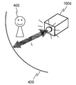
- a diagram schematically showing the situation of shooting when the subject is relatively far away A diagram schematically showing the shooting situation when the subject is relatively close
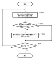
- the flowchart which shows the example of the process at the time of imaging
- FIG. 1 is a perspective view showing the external appearance of a video camera (video imaging device) 100a that captures video.
- the video camera 100a has a function of shooting, recording, and playing back a stereoscopic video.
- the video camera 100a further has a function of extracting and reproducing a plurality of parts for digest reproduction from a stereoscopic video, and a function of recording a video signal capable of such digest reproduction.
- the “stereoscopic image” means a pair of images having parallax.
- data indicating a stereoscopic image may also be referred to as a “stereoscopic image”.
- a stereoscopic video can be reproduced by processing a pair of video suitably combined.
- “Digest playback” means that a plurality of partial scenes of a video are extracted and continuously played back.
- the video camera 100a includes two types of lens groups 200R and 200L, and shoots a stereoscopic image by shooting using these lens groups.
- the lens group 200L is a smaller lens than the lens group 200R.
- the lens group 200R has a zoom lens, but the lens group 200L does not have a zoom lens.
- the video shot through the lens group 200L is subjected to an electronic zoom process, and an area in the same range as the video shot through the lens group 200R is extracted. As a result, two images constituting a stereoscopic image are generated.
- the distance between the lens group 200R and the lens group 200L affects the magnitude of the parallax of the stereoscopic image to be captured, and can be set to be approximately the same as the distance between the left and right eyes of a person, for example. Furthermore, the lens group 200R and the lens group 200L can be arranged so as to be positioned on substantially the same horizontal plane when the video camera 100a is placed parallel to the ground. This is because when a person looks at an object, it is common to see the left and right eyes in a substantially horizontal state.
- the lens group 200R and the lens group 200L may be arranged so that their optical centers are located on the same plane parallel to the imaging surface of the imaging device in the video camera 100a. This is because the lens group 200R and the lens group 200L are positioned at substantially the same distance from the subject in order to acquire a natural stereoscopic image. Strictly speaking, the lens groups 200R and 200L are designed in consideration of the positional relationship with the image pickup element arranged in the subsequent stage.
- the lens groups 200R and 200L are on the same plane parallel to the imaging surface, the positions of the same subject in the left and right image frames constituting the stereoscopic video satisfy an epipolar constraint condition. For this reason, in the signal processing for generating a stereoscopic video, if the position of the subject on one video plane is determined, the position of the subject in the other video can be calculated relatively easily.
- the lens group 200R is provided in the front part of the main body of the video camera 100a, and the lens group 200L is provided on the back surface of the video display unit (display) 212 for confirming the captured video.
- the monitor unit 104 displays the captured video on the side opposite to the side where the subject is located (the rear side of the video camera 100a).
- the video camera 100a processes a video shot using the lens group 200R as a right-eye viewpoint video and a video shot using the lens group 200L as a left-eye viewpoint video.
- the reason why the lens groups 200R and 200L are configured differently is to reduce the size and cost of the entire apparatus by simplifying the lens group 200L.
- this is not the essence of the technology in the present disclosure, and the two lens groups 200R and 200L may have the same structure.
- FIG. 2 is a block diagram showing a schematic configuration of the video camera 100a.
- the video camera 100a includes lens groups 200R and 200L, image sensors (image sensors) 201R and 201L, video AD converters (Analog-to-Digital Converters) 202R and 202L, a signal processor 203, a video signal compressor 204, and lens control.
- I / F Interface
- the lens groups 200R and 200L are optical systems that adjust light incident from a subject in order to form a subject image on the imaging surfaces of the imaging elements 201R and 201L corresponding thereto.
- the lens group 200R includes a plurality of lenses having different characteristics, and the focal length and zoom magnification (image magnification) can be changed by changing the distance between the lenses. Adjustment of the focal length and zoom magnification may be performed manually by a video camera photographer, or may be automatically performed by the control unit 300 through a lens control module 205 described later.
- the lens group 200L is a single focus lens and does not have a function of adjusting the focal length or zoom magnification.
- Image sensors 201R and 201L convert light incident through the lens groups 200R and 200L into electrical signals.
- the image sensors 201R and 201L are typically CCD or C-MOS sensors.
- the image sensors 201R and 201L have a plurality of photosensitive cells that output electrical signals corresponding to the amount of received light by photoelectric conversion. As a result, an image signal corresponding to the image formed on the imaging surface is output.
- the image sensors 201R and 201L include chromaticity space information of the three primary color points, white coordinates, and gain information of at least two of the three primary colors, color temperature information, ⁇ uv (delta uv), And information such as gamma information of the three primary colors or the luminance signal may be output.
- These pieces of information generated by the imaging elements 201R and 201L may be input to an attribute information extraction unit 305 described later in the control unit 300.
- the video AD converters 202R and 202L are circuits that convert analog electric signals output from the image sensors 201R and 201L into digital signals, respectively. As a result, the image for the right eye acquired by the image sensor 201R and the image for the left eye acquired by the image sensor 201L are output as digital signals, respectively.
- the signal processing unit 203 performs processing for matching the angle of view and the number of pixels in both the left and right videos output from the video AD conversion units 202R and 202L. As a result, left and right images having the same number of pixels for the same shooting range are generated. Details of the processing for adjusting the angle of view and the number of pixels are disclosed in Patent Document 4, for example. The entire description of Patent Document 4 is incorporated herein by reference. Note that when the lens groups 200R and 200L and the image sensors 201R and 201L have the same configuration, the angle-of-view matching and the number-of-pixels matching processing are not necessary.
- the signal processing unit 203 further converts both left and right video signals into a predetermined video signal format such as NTSC (National Television System Committee) or PAL (Phase Alternating Line).
- the signal processing unit 203 converts the digital signal from the video AD conversion unit 202 into a digital video signal (video data) that complies with the number of horizontal lines, the number of scanning lines, and the frame rate specified by, for example, NTSC.
- the output from the signal processing unit 203 is input to the video analysis unit 303 in the control unit 300.
- the signal processing unit 203 can be configured by, for example, an IC for video signal conversion. Alternatively, the above processing can be realized by a suitable combination of an IC and a program that defines signal processing.
- the so-called full high-definition method in which the number of effective pixels of one video frame is 1920 in the horizontal direction and 1080 in the vertical direction, or the number of effective pixels of one video frame is 1280 in the horizontal direction and 720 in the vertical direction. There may be a method or the like.
- the video signal compression unit 204 performs predetermined coding conversion on the digital video signal output from the signal processing unit 203 to compress the data amount.
- the encoding conversion there may be encoding schemes such as MPEG (Moving Picture Experts Group) 2, MPEG4, and H264.
- the output of the video signal compression unit 204 is input to the multiplexing unit 308 in the control unit 300.
- the video signal compression unit 204 can be configured by an IC for signal compression / decompression, for example.
- the lens control module 205 is configured to detect the state of the lens groups 200R and 200L and operate the lens groups 200R and 200L.
- the lens control module 205 includes a lens control motor and a lens position sensor.
- the lens position sensor detects distances or positional relationships between a plurality of lenses constituting the lens groups 200R and 200L.
- the lens position sensor outputs the detection signal to the lens control unit 301 in the control unit 300.
- the lens control module 205 has two types of lens control motors.
- the first lens control motor moves the lens group 200 ⁇ / b> R in the optical axis direction based on a control signal from the lens control unit 301 in the control unit 300.
- the second lens control motor is a surface orthogonal to the optical axis of at least one lens (camera shake correcting lens) included in the lens groups 200R and 200L based on a control signal from the lens control unit 301 in the control unit 300. Move within. As a result, image blur can be corrected.
- the posture detection unit 206 detects the posture of the video camera 100a main body.
- the posture detection unit 206 includes an acceleration sensor, an angular velocity sensor, and an elevation angle / decline angle sensor. With these sensors, it is possible to recognize the posture of the video camera 100a during shooting.
- the acceleration sensor and the angular velocity sensor can respectively detect the attitudes in the orthogonal three-axis directions (the vertical direction, the front-rear direction, and the left-right direction of the video camera 100a).
- a signal from the posture detection unit 206 is input to the lens control unit 301 in the control unit 300.
- the posture detection unit 206 is not limited to the above configuration, and may be configured by only a part of the sensor or may include a sensor other than the sensor.
- the external input unit 207 is an interface for inputting information from the outside to the video camera 100a.
- a signal from the external input unit 207 is input to the attribute information extraction unit 305 in the control unit 300.
- the signal from the external input unit 207 is input only to the attribute information extraction unit 305 in the control unit 300, but can also be input to a part corresponding to the input operation of the lens control unit 310 and the like.
- various information from the outside is input to the video camera 100a via the external input unit 207.
- the external input unit 207 includes an input button that is one of input interfaces that accepts input of information from the user, a reception unit that receives shooting index information input by communication from the outside, and the video camera 100a is a tripod.
- a tripod sensor for detecting whether or not the camera is installed on the camera For example, when the user operates an input button, various requests from the user such as start and end of shooting, an operation of inserting marking into a video being shot, and input and setting of attribute information and evaluation thereof described later are performed. This can be transmitted to the video camera 100a. That is, the external input unit 207 constitutes an input unit that inputs at least one of attribute information and an evaluation value, which will be described later, to the recording unit 330 in accordance with a user input operation.
- the shooting index information is an identifier used for identifying each shooting such as a number for identifying a shooting scene at the time of shooting a movie and a number indicating the number of shooting times.
- the tripod sensor is composed of a switch provided in a portion where the tripod of the video camera 100a is fixed. The tripod sensor can determine whether a tripod is being used.
- the microphone 208 converts sound around the video camera 100a into an electric signal and outputs it as an audio signal.
- the audio signal is input to the audio AC conversion unit 209.
- the audio AD conversion unit 209 converts an analog audio signal output from the microphone 208 into a digital audio signal (audio data).
- the audio AD conversion unit 209 is configured by an AD conversion circuit, for example.
- the converted digital audio signal is input to the audio analysis unit 304 and the audio signal compression unit 210 in the control unit 300.
- the audio signal compression unit 210 converts the digital audio signal output from the audio AD conversion unit 209 using a predetermined encoding algorithm. For encoding, methods such as MP3 (MPEG Audio Layer-3) and AAC (Advanced Audio Coding) can be used.
- the audio signal compression unit 210 is configured by a compression IC, for example.
- the video signal decompression unit 211 decodes the video signal output from the digest reproduction unit 309 described later in the control unit 300 and the parallax amount adjusted by the automatic depth setting unit 310.
- the output from the video signal expansion unit 211 is input to the video display unit 212.
- the video signal decompression unit 211 is composed of, for example, an IC for video signal decompression.
- the video display unit 212 is a display that displays video recorded on a recording medium in the video camera 100a and video captured by the video camera 100a in real time.
- the video display unit 212 displays various information such as information related to shooting and device information in addition to the above video.
- the video display unit 212 is configured by a liquid crystal display having a touch sensor, for example.
- the video display unit 212 having such a touch sensor also functions as the external input unit 207.
- the audio signal expansion unit 213 decodes the audio signal output from the digest reproduction unit 309 in the control unit 300.
- the audio signal decoded by the audio signal expansion unit 213 is input to the audio output unit 214.
- the audio signal expansion unit 213 is configured by an audio signal expansion IC, for example.
- the audio output unit 214 outputs audio accompanying the video.
- the audio output unit 214 also outputs a warning sound to notify the user from the video camera 100a.
- the audio output unit 214 is, for example, a speaker or an earphone terminal.
- the output I / F 215 is an interface for outputting a video signal from the video camera 100a to the outside.
- the output I / F 215 may be a cable interface for connecting the video camera 100a and an external device with a cable, or a memory card interface for recording a video signal on a memory card.
- the control unit 300 is a functional unit that controls the entire video camera 100a.
- the control unit 300 includes an image sensor 201R, a signal processing unit 203, a video signal compression unit 204, a lens control module 205, an attitude detection unit 206, an external input unit 207, an audio AD conversion unit 209, an audio signal compression unit 210, and a video signal decompression.
- the unit 211, the audio signal expansion unit 213, the output I / F 215, and the recording unit 330 are configured to be able to exchange signals.
- the control unit 300 is composed of a CPU.
- the control unit 300 executes various controls of the video camera 100a by reading and executing a program stored in the recording unit 330.
- control executed by the control unit 300 examples include control of focal lengths and zooms of the lens groups 200R and 200L, processing of input signals from the posture detection unit 206 and the external input unit 207, signal processing unit 203, Examples include IC operation control such as the video signal compression unit 204, the audio signal compression unit 210, the video signal expansion unit 211, and the audio signal expansion unit 213.
- the signal may be appropriately AD-converted or DA-converted between the control unit 300 and the lens control module 205 or the like.
- the control unit 300 can be configured only by hardware such as an integrated circuit.
- the clock oscillator 320 outputs a clock signal serving as a reference for processing operation to the control unit 300 or the like operating in the video camera 100a.
- the clock oscillator 320 can use a single clock or a plurality of clocks depending on an integrated circuit to be used and data to be handled. Further, an arbitrary multiple of the clock signal of one oscillator may be used.
- the recording unit 330 may include a ROM (Read Only Memory), a RAM (Random Access Memory), and an HDD (Hard Disk Drive).
- the ROM is a recording medium that stores a program processed by the control unit 300 and various data for operating the program.
- the RAM is used as a memory area used by the control unit 300 when executing a program.
- the RAM can also be used as a memory area of the IC.
- the HDD stores various data such as video data and still image data encoded and converted by the video signal compression unit 204.
- a program executed by the control unit 300 is recorded in the HDD. Note that this program is not limited to the HDD, and may be recorded in a semiconductor memory, or may be stored in a portable recording medium such as a CD-ROM or DVD.
- control unit 300 also has a configuration for exhibiting the same function as that of a general video camera, for example, a configuration for recording or playing back a captured video.
- the control unit 300 includes a lens control unit 301 that controls the lens control module 205, an imaging control unit 302 that controls the imaging elements 201R and 201L, and a video analysis unit 303 that analyzes a stereoscopic video output from the signal processing unit 203.
- An audio analysis unit 304 that analyzes the output from the audio AD conversion unit 209, an attribute information extraction unit 305 that extracts attribute information in the video, a scene evaluation unit 306 that evaluates a scene, and reproduction information for digest reproduction
- the control unit 300 implements various processes to be described later by reading and executing the program recorded in the recording unit 330.
- the video analysis unit 303 detects a subject included in the video, separates the subject and the background, analyzes the object and background outline, color, texture, object recognition, and further analyzes the composition of the video.
- the digest reproduction unit 309 and the automatic depth setting unit 310 have functions as an interface and a digest video generation unit.
- the lens control unit 301 receives the detection signal of the lens position sensor of the lens control module 205 and the detection signal of various sensors of the posture detection unit 206. Based on these detection signals and information generated by other components such as the image sensors 201R and 201L, the lens control unit 301 sends a control signal for properly arranging the lens groups 200R and 200L to the lens control motor. Output. In this way, the lens control unit 301 performs zoom control, focus control, and camera shake correction control. The lens control unit 301 also sends these control signals to the attribute information extraction unit 305. Note that detection signals from various sensors of the posture detection unit 206 are also input to the attribute information extraction unit 305.
- the imaging control unit 302 controls the operation of the imaging elements 201R and 201L, for example, the exposure amount at the time of shooting, the shooting speed, and sensitivity.
- the control signal output from the imaging control unit 302 is transmitted not only to the imaging elements 201R and 201L but also to the attribute information extraction unit 305.
- the video analysis unit 303 extracts video features based on the video data from the signal processing unit 203.
- the video analysis unit 303 detects video color information (for example, the distribution of colors included in the video) and white balance information.
- the color distribution can be detected by confirming color information included in the data forming the digital video signal.
- the video analysis unit 303 detects a face from the video when the video includes a human face. The face detection can be realized by using a known method such as pattern matching.
- the voice analysis unit 304 analyzes the voice data from the voice AD conversion unit 209 and extracts characteristic sounds.
- the characteristic sound here may be, for example, a photographer's voice, pronunciation of a specific word, cheers, gunshots, and the like. If the specific frequencies of these sounds (voices) are registered in advance, it can be determined whether or not sounds close to those sounds are included. In addition to this, for example, when the sound input level is a predetermined level or higher, it may be determined that the sound is a characteristic sound.
- the attribute information extraction unit 305 extracts attribute information about the video.
- the attribute information is information indicating video attributes, and may include, for example, information related to shooting (hereinafter also referred to as “shooting information”), information input from the outside, and other information.
- Signals are input to the attribute information extraction unit 305 from the imaging elements 201R and 201L, the posture detection unit 206, the external input unit 207, the lens control unit 301, the imaging control unit 302, the video analysis unit 303, and the audio analysis unit 304. .
- the attribute information extraction unit 305 extracts attribute information based on these signals.
- Attribute information includes distance information of the subject in the video.
- the distance information is information indicating the distance between the subject and the video camera 100a, and indicates the amount of protrusion or depth of the subject. This distance information is defined as the distance between the main subject (such as a person's face) in focus in each image frame and the video camera 100a. This distance information can be obtained from the focal lengths of the lens groups 200R and 200L, for example. Alternatively, the distance information may be obtained by any of the following methods.
- methods for measuring the subject distance include a method using a plurality of cameras and a method using a dedicated camera for distance measurement.
- the method using a plurality of cameras for example, two cameras are installed on the epipolar line so that their optical axes are parallel to each other (parallel method), and the amount of parallax generated for the same object in the captured left and right images Based on this, depth information, that is, distance information can be obtained.
- distance information is obtained by using two sets of imaging systems (the optical system 200R / L, the imaging element 201R / L, and the video AD conversion unit 202R / L) as the two cameras. it can.
- the time from when the object is irradiated with light from a light source having a specific light emission pattern and the reflected light from the object is detected as in the TOF (Time of Flight) method. Ranging can be performed by measuring.
- the video camera 100a is provided with a distance measurement camera in addition to the components shown in FIG.
- a distance measurement method using a laser such as a laser range finder used in the field of robots
- a distance measurement method using ultrasonic waves or millimeter waves is there.
- the distance information acquisition method is not limited to a specific method.
- the attribute information includes, in addition to distance information, for example, information related to photographing such as the state of the photographing apparatus at the time of photographing and camerawork, information relating to video by CG, information other than distance information relating to the subject and background included in the video itself, video Information related to audio and information related to video editing content can be included.
- distance information for example, information related to photographing such as the state of the photographing apparatus at the time of photographing and camerawork, information relating to video by CG, information other than distance information relating to the subject and background included in the video itself, video Information related to audio and information related to video editing content can be included.
- attribute information related to the photographing apparatus at the time of photographing include focal length, zoom magnification, exposure, photographing speed, sensitivity, color space information of three primary colors, white balance, gain information of at least two of the three primary colors, Color temperature information, ⁇ uv (delta uv), gamma information of three primary colors or luminance signals, color distribution, face recognition information, camera posture (acceleration, angular velocity, elevation angle, depression angle, etc.), shooting time (shooting start time, end time), Examples include shooting index information, user input, frame rate, sampling frequency, and the like.
- the attribute information extraction unit 305 can extract the focal length and zoom magnification as attribute information in addition to the subject distance information based on, for example, a control signal output from the lens control unit 301. Further, the attribute information extraction unit 305 detects a camera posture (acceleration, angular velocity, elevation angle, depression angle, etc.) based on a signal output from the posture detection unit 206, and captures panning, tilting, and the like from the camera posture. Can be extracted as attribute information. Furthermore, based on these camera works, a fixed shooting part after camera work (a part shot with the video camera 100a being stationary) can be extracted as attribute information. As described above, the attribute information extraction unit 305 may extract the attribute information from the input signal itself, or may extract the attribute information by combining or analyzing the input signal.
- a camera posture acceleration, angular velocity, elevation angle, depression angle, etc.
- the scene evaluation unit 306 evaluates the video of the part including each attribute information and assigns the evaluation (value) to the part. Details of this evaluation will be described later.
- the reproduction information generation unit 307 selects a part (scene) to be reproduced and specifies information (hereinafter referred to as “reproduction information”) for specifying a part to be digest reproduced. Generate. Details of the reproduction information will be described later.
- the multiplexing unit 308 multiplexes the encoded video data output from the video signal compression unit 204, the encoded audio data output from the audio signal compression unit 210, and the reproduction information output from the reproduction information generation unit 307. Output.
- the data multiplexed by the multiplexing unit 308 is stored in the recording unit 330.
- a multiplexing method for example, there is a technique such as MPEG TS (Transport Stream). However, it is not limited to this. In this embodiment, the case of multiplexing is shown as an example, but it is not always necessary to multiplex.
- the processes of the attribute information extraction unit 305, the scene evaluation unit 306, the reproduction information generation unit 307, and the multiplexing unit 308 are sequentially executed during shooting or immediately after shooting.
- the digest playback unit 309 generates a 3D video for digest playback based on the user input after shooting.
- the digest reproduction unit 309 reads the multiplexed data recorded in the recording unit 330 and outputs the encoded video data and encoded audio data of the scene to be digest reproduced to the automatic depth setting unit 310 according to the reproduction information.
- the automatic depth setting unit 310 performs a process of adjusting the depth amount (protruding amount) of the stereoscopic video as necessary in order to ensure the safety of the stereoscopic video and improve the sense of reality.
- the automatic depth setting unit 310 adjusts the parallax amount of at least some of the image frames before and after the scene change so that the pop-out amount of the subject changes from the original value before and after the scene change of the digest video. A specific example of this adjustment method will be described later.
- the automatic depth setting unit 310 outputs the adjusted encoded video data and encoded audio data to the video signal expansion unit 211 and the audio signal expansion unit 213, respectively.
- the output encoded video data and encoded audio data are decoded by the video signal expansion unit 211 and the audio signal expansion unit 213, respectively, and output from the video display unit 212 and the audio output unit 214. In this way, digest reproduction in which only a specific part is extracted from the video is executed.
- the digest video may be recorded in the recording unit 330 instead of being reproduced.
- the minimum value at which parallax can be detected is about 1.2 seconds (one second is 1/600). If this value is smaller than this value, parallax cannot be detected.
- the solid fusion limit value which is said to be determined by Panum's fusion limit, is about 2 degrees, and it is said that an unstable double image can be formed if this value is larger than this value. In particular, from 2 degrees to 5 degrees is an unstable region with a strong load, and a stable fusion region is said to be about 70 minutes or less (one minute is 1/60 of a degree) or less.
- a guideline for adjusting the depth amount (protruding amount) of a stereoscopic image that is safe and realistic it may be adjusted between about 1 minute and 70 minutes.
- safe and powerful 3D images can be obtained even if they are adjusted more than twice in a short time. ing.
- characters and graphics CG that describe a scene are pasted and displayed in a three-dimensional space, it is generally performed within this adjustment range.
- by performing the depth adjustment within this adjustment range it is possible to perform a digest playback of a stereoscopic video that is safe and more realistic.
- FIG. 3 is a schematic diagram illustrating a configuration of an image captured by the video camera 100a.
- FIG. 4 is a diagram illustrating an example in which a clip is divided into a plurality of scenes. In FIG. 4, each scene is specified by “start time” and “end time”, but each scene may be specified by other information, for example, frame numbers (scene start frame number and end frame number). .
- a unit of video shot until the user gives an instruction to start shooting and gives an instruction to end shooting or pause shooting is called a “clip”. That is, when the user repeats the start of shooting and the end or pause of shooting many times, a plurality of clips are generated.
- One clip is composed of at least one “scene”.
- a “scene” is a series of logically connected images, and is composed of at least one “frame”.
- a “frame” is an individual image that is the smallest unit constituting a video. In this specification, “frame” may be referred to as “image frame”.
- a “scene” may be set at a frame where the screen changes greatly.
- the video analysis unit 303 may calculate a motion vector between successive frames, and the “scene” boundary may be when the magnitude of motion (ie, the amount of change in the motion vector) is greater than a predetermined value. That is, an image included between the two boundaries set in this way is set as one “scene”.
- the “scene” may be divided based on other shooting information.
- the “scene” may be divided by a button input from the photographer.
- the “scene” in the “clip” is configured based on the clear intention of the photographer.
- a specific part in the “clip” can be treated as a “scene”.
- only the important part of the video can be handled as a “scene” from the video.
- a part including specific attribute information may be handled as one “scene”.
- a video having a predetermined time width including attribute information assumed to be important can be set as a “scene”.
- only important parts are extracted as “scenes”.
- a “clip” includes a plurality of “scenes” discretely.
- the “scene” can be set arbitrarily.
- an important part included in a video is handled as a “scene”.
- FIG. 5 is a diagram showing an example of a table showing correspondence between various attribute information used when evaluating a video and an evaluation value for each attribute information. This table is recorded in the recording unit 330. The scene evaluation unit 306 evaluates the video by referring to this table.
- evaluation values are set individually for each attribute information.
- the higher the evaluation value the higher (preferred) the evaluation.
- clip-in (shooting start portion) and clip-out (shooting immediately before the end of shooting) are an introduction portion and an end portion of the image, respectively, and it is estimated that the logical meaning of the image is high. Therefore, an evaluation value “100” is set for clip-in (A), and an evaluation value “90” is set for clip-out (F). Since zoom-up (D) and zoom-down (G) as camera work at the time of shooting increase the degree of attention to a specific subject, an evaluation value “30” is set.
- the subject distance-near (K) indicates that the amount of protrusion of the main subject is large, and the evaluation value “70” is set.
- subject distance-medium (L) indicates that the amount of protrusion of the main subject is medium, and the evaluation value “10” is set.
- a powerful stereoscopic video digest video is generated.
- whether or not the subject distance-near (K) or subject distance-medium (L) is satisfied is determined based on whether the distance information is within a predetermined range. For example, if the subject distance determined from the distance information is shorter than the first threshold, it corresponds to subject distance-near (K), and if the subject distance is longer than the first threshold and shorter than the second threshold, the subject Distance-medium (L).
- an evaluation value “50” is set for the detection of a face (Z).
- an evaluation value of “100” is set, and when the face of a specific person B is detected (Y)
- the value “80” is set.
- the user's face and the evaluation value for the face can be set as appropriate by the user, as will be described in detail later. That is, it is not only that a person is photographed, but a high evaluation value can be assigned to a video image of a specific person with the intention of the user.
- the evaluation may be not only positive evaluation, that is, favorable evaluation, but also negative evaluation, that is, unfavorable evaluation. For example, since the image blur may be a video that is difficult for the viewer to see, a negative evaluation value is assigned to a scene having such attribute information.
- the evaluation is quantified, but it is not limited to such an example.
- codes such as A, B, C,... May be used for evaluation.
- superiority or inferiority may be determined in advance for the codes used for evaluation (for example, A is the highest evaluation).
- evaluation of codes such as A, B, and C may be freely set by the user's intention.
- the scene evaluation unit 306 gives an evaluation value corresponding to the attribute information to the portion of the video from which the attribute information is extracted by the attribute information extraction unit 305 based on the table. A predetermined number of scenes are extracted based on the evaluation value. In this manner, the scene evaluation unit 306 extracts in advance a characteristic video portion that can be used for digest playback as a scene, which is larger than the number of scenes to be digest played back. For example, the scene evaluation unit 306 extracts a video having a predetermined time width including a portion having attribute information with a high evaluation value as one scene. Then, a predetermined number of scenes are extracted in descending order of evaluation values. The predetermined number may be arbitrarily set by the user, or may be set in advance as a fixed value.
- a part having attribute information with a high evaluation value is extracted as a scene when a part including the same attribute information is extracted as a scene before that, it may not be extracted as a scene. Good. In this way, it is possible to prevent only scenes having the same attribute information from being extracted.
- a part having specific attribute information for example, face detection of the person A, face detection of the person B, etc. may be preferentially extracted as a scene.
- the scene evaluation unit 306 After extracting a predetermined number of scenes, the scene evaluation unit 306 extracts scenes to be digest-reproduced from the extracted scenes based on predetermined extraction conditions. For example, if the extraction condition is “three in descending order of evaluation value”, the scene evaluation unit 306 extracts the three scenes with the highest evaluation value. This number may be arbitrarily set by the user. Also, if the extraction condition is that “the extraction is performed in descending order of the evaluation value and the total time is within a predetermined time”, the scene evaluation unit 306 evaluates the evaluation value so that the total time is within the predetermined time. Are extracted in order from the top scene.
- the predetermined time may be set to a predetermined value in advance, or may be arbitrarily set by the user.
- the scene evaluation unit 306 extracts scenes whose evaluation value is equal to or greater than the predetermined value regardless of the number and the total time.
- This predetermined value may be arbitrarily set by the user.
- the scene evaluation unit 306 can extract a scene from various viewpoints based on the assigned evaluation value. Note that the extraction conditions may be set as appropriate by the user, or some conditions may be set in advance.
- a value obtained by adding an evaluation value assigned to the content of each attribute information may be used as the evaluation value of the scene.
- the highest evaluation value from among the plurality of attribute information or the average value of the evaluation values of the plurality of attribute information may be used as the evaluation value of the scene.
- the video camera 100a is not limited to one table that defines the correspondence between the attribute information and the evaluation value, and may be configured to appropriately select a table used for scene evaluation.
- the video camera 100a corresponds to a shooting mode (for example, landscape shooting, person (portrait) shooting, sports shooting, still life shooting, etc.) from among a plurality of tables that define the correspondence between attribute information and evaluation values.
- the optimum table may be selected.
- a one-to-one table is not prepared in advance for each shooting situation, but rather than the type of shooting situation. A small number of tables may be prepared.
- a plurality of tables may be combined (e.g., each evaluation value is added at a constant ratio) according to the shooting situation.
- a table corresponding to the shooting situation can be set.
- FIG. 6 is a diagram illustrating an example of a result obtained when the scene evaluation unit 306 extracts attribute information from a certain video and assigns an evaluation value.
- the horizontal axis in FIG. 6 represents time (scene), and the vertical axis represents the evaluation value.
- a portion near time 0 has “clip-in” attribute information A meaning that it is immediately after the start of shooting, and an evaluation value “100” is given.
- the portion having the attribute information K and L is a portion where the main subject is relatively close and it is determined that the three-dimensional characteristics are high.
- the part having the attribute information K is given the evaluation value “70”, and the part having the attribute information L is given the evaluation value “10”.
- the portion having the attribute information C is a portion in which the user is shooting still after panning or tilting the video camera 100a. Since it can be determined that the portion after camera work such as pan and tilt has high value as a video, such still shooting after camera work is set as attribute information. An evaluation value “40” is assigned to the portion having the attribute information C.
- the part having attribute information D is a part that is photographed by zooming up or down.
- Zoom-up or zoom-down reflects the user's intention regarding shooting and can be determined to be important, and is therefore set as attribute information.
- An evaluation value “30” is assigned to the portion having the attribute information D.
- the evaluation value may be changed between zoom-up and zoom-down. For example, the evaluation value may be set higher because it is determined that zooming up has a greater intention to gaze at a subject to be photographed than zooming down.
- the portion having the attribute information E is a portion where the video camera 100a is photographed while panning, tilting, or the like. Camera work such as panning and tilting is set as attribute information because it can be determined that the shooting intention of the user who wants to follow the shooting target is reflected. An evaluation value “25” is assigned to the portion having the attribute information E.
- the part having the attribute information I is a part where the image is accompanied by image blurring. In this case, since the video is shaking, the video tends to be difficult for viewers to see. Therefore, a negative evaluation value is given. Specifically, the evaluation value “ ⁇ 20” is assigned to the portion having the attribute information I.
- the part having the attribute information J is a part where the ground is photographed. This is a phenomenon that easily occurs when the user walks with the video camera 100a in his / her hand while continuing to shoot without pressing the shooting stop button. In this case, since it can be determined that the user's special intention is not reflected in the video, a negative evaluation value is assigned. Specifically, the evaluation value “ ⁇ 10” is assigned to the portion having the attribute information J.
- the part having the attribute information X is a part in which the face of the person A is reflected.
- the video analysis unit 303 recognizes that the subject in the captured video is a person's face, and the recognized face matches the face of a specific person previously recorded in the recording unit 330 or the like. It is determined whether or not. Based on this result, the scene evaluation unit 306 can extract a part in which the face of a specific person is captured from the video. An evaluation value “100” is assigned to the portion having the attribute information X.
- FIGS. 7A to 7D there are cases as shown in FIGS. 7A to 7D as examples of images in which a person's face is photographed.
- the scene evaluation unit 306 displays an evaluation value (in the example of FIG. “100” is assigned to the face of the person A, and “80” is assigned to the face of the person B.
- the scene evaluation unit 306 evaluates the evaluation value with the higher evaluation value of the faces of the persons A and B. It may be a value.
- “100” that is the evaluation value of the face of the person A is the evaluation value. 6 is a portion in which the faces of both the person A and the person B are shown.
- an evaluation value obtained by averaging both evaluation values may be used. In this case, in the example shown in FIG. 5, the evaluation value is “90” from (100 + 80) / 2.
- a distribution ratio may be set for each evaluation value and summed up.
- the distribution ratio may be set for each evaluation value such that the larger the face size on the video is, the higher the distribution ratio is.
- the evaluation value is “92.5” from (100 ⁇ 5 + 80 ⁇ 3) / 8. It becomes.
- the size of the face on the image is likely to reflect the distance from the camera to the subject, and this method can increase the degree of influence by setting a large distribution ratio for nearby subjects. .
- the distribution ratio may be set for each evaluation value according to the center position of the faces of the persons A and B and the distance from the center of the screen or the salient area (Saliant area) on the screen. Specifically, the distribution ratio may be higher as the distance is shorter.
- region is an area
- a distribution ratio may be set and added to the evaluation value of the face of the person A and the evaluation value of the face of another person according to the number of people who are photographed.
- the evaluation value “54.5” is given from (100 ⁇ 1 + 50 ⁇ 10) / 11.
- For face detection evaluate the position on the screen, face size, face orientation, smile level, eye opening / closing information, face emotion level information, and increase or decrease the evaluation value accordingly. You may let them.
- the scene evaluation unit 306 extracts six scenes in descending order of the evaluation value.
- six scenes are labeled # 1 to # 6 in order of time.
- the scene evaluation unit 306 when the extraction condition “3 in descending order of evaluation value” is set, the scenes to be digest-reproduced with the top three # 1, # 2, and # 5 evaluation values Extract as
- the reproduction information generation unit 307 generates reproduction information that is information for specifying a scene to be digest reproduced according to the scene extracted by the scene evaluation unit 306.
- the reproduction information may be indicated by the start time and end time of the scene to be reproduced as shown in FIG. In this case, it is effective to search for a reference screen by separately recording a representative frame in each scene (a frame having the highest evaluation in the scene).
- the reproduction information is not limited to the above contents, and for example, a scene to be reproduced may be specified by a frame number.
- the position (location) of the corresponding scene in the multiplexed data generated by the multiplexing unit 308 described later may be used as the scene specification.
- reproduction information may be generated using time information such as PTS (Presentation Time Stamp) or DTS (Decoding Time Stamp).
- PTS Presentation Time Stamp
- DTS Decoding Time Stamp
- a method of recording playback information in a PlayList file or the like May be used.
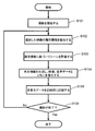
- FIG. 9 is a flowchart showing the flow of processing from shooting, scene evaluation, generation of reproduction information, and recording.
- the control unit 300 of the video camera 100a starts shooting in step S101. Shooting is started based on an input from the external input unit 207 such as an input button.
- the attribute information extraction unit 305 determines the video attribute based on the detection result of the posture detection unit 206, the control information of the lens control unit 301, the analysis results of the video analysis unit 303 and the audio analysis unit 304, and the like. Extract information.
- the scene evaluation unit 306 assigns an evaluation value to each part of the video based on the attribute information extracted by the attribute information extraction unit 305. Thereafter, the scene evaluation unit 306 extracts some characteristic scenes, and further extracts a scene to be digest reproduced from them.
- step S104 the reproduction information generation unit 307 generates reproduction information based on the scene to be digest reproduced extracted by the scene evaluation unit 306. Then, the multiplexing unit 314 multiplexes the generated reproduction information together with the encoded video data and the encoded audio data.
- the control unit 300 records the multiplexed data in the recording unit 330 in step S105.
- step S106 the control unit 300 determines whether or not there is an end of photographing from the external input unit 207. If there is no input for the end of shooting, the process returns to step S102 to continue shooting. On the other hand, if there is an input for the end of shooting, shooting is ended.
- the digest playback unit 309 reads the playback information recorded in the recording unit 330, and generates a video for digest playback based on the read information. Specifically, the digest playback unit 309 corresponds to the video and audio information recorded in the recording unit 330 based on information such as the start time and end time of each scene to be digest played as shown in FIG. Extract partial scenes. Then, the automatic depth setting unit 310 adjusts the pop-out amount (parallax amount) of the extracted scene video as necessary, and then reproduces the scene.
- FIG. 10A is a flowchart showing the flow of processing during digest playback.
- step S201 the digest reproduction unit 309 reads the multiplexed data recorded in the recording unit 330.
- step S202 the digest reproduction unit 309 decomposes the read multiplexed data and extracts reproduction information.
- step S203 the digest playback unit 309 selects a plurality of scenes for digest playback based on the playback information.
- step S204 the automatic depth setting unit 310 obtains the change amount of the subject distance between the selected scenes.
- This amount of change can be obtained, for example, by taking the difference of subject distance information in a plurality of image frames before and after the boundary between two consecutive scenes.
- step S205 it is determined whether there is a scene in which the amount of change in the subject distance with respect to the immediately preceding scene exceeds a predetermined threshold. If the corresponding scene exists, the process proceeds to step S206, and if not, the process proceeds to step S207.
- step S ⁇ b> 206 the automatic depth setting unit 310 determines the video of the scene so that the subject distance is smaller than the threshold in a scene determined that the change amount of the subject distance with respect to the immediately preceding scene is equal to or greater than a predetermined threshold.
- the amount of parallax is corrected. A specific example of the parallax amount correction method will be described later.
- the process proceeds to step S207.
- step S207 the automatic depth setting unit 310 outputs the encoded video data and the encoded audio data to be reproduced to the video signal expansion unit 211 and the audio signal expansion unit 213, and the video display unit 212 and the audio output unit 214 are output. To play video and audio.
- digest playback is performed by extracting only a specific scene from the video.
- the automatic depth setting unit 310 adjusts the parallax amount between the left and right images in order to adjust the subject distance.
- the amount of parallax between the left and right images is represented by a depth map.
- the depth map is, for example, information for each pixel having a value in accordance with the amount of parallax and a portion having no parallax in the video.
- the “parallax amount” is an amount indicating how many pixels the corresponding points in the other image are shifted when the left and right images are used as a reference. As the amount of parallax increases, the pop-out amount increases.
- the depth map indicates the amount of parallax between the left and right images, that is, the distance information.
- a depth map is typically created for each frame of a video.
- Examples of the parallax correction method include the following methods. First, based on the distribution of distance information indicated by the depth map, the frequency of occurrence of each part of the nearest distance (Dnear), the farthest distance (Dfar), and the average distance (Davr) in the video is obtained. Next, a difference between (Dnear) and (Dfar) is calculated to obtain a distance distribution width (Dwidth). As a first method of correcting the amount of parallax, the depth can be corrected back and forth by shifting the average distance (Davr) in a DC manner. That is, the distance of the entire image can be uniformly increased or decreased by that amount so that (Davr) is increased or decreased by a predetermined amount.
- the depth may be adjusted by enlarging or reducing the distance distribution width (Dwidth). That is, a method may be employed in which at least one of a portion corresponding to Dnear and a portion corresponding to Dfar is shifted back and forth, and other portions are shifted in conjunction therewith. In these calculations, if weighting is performed according to the frequency of occurrence of the distance, a 3D image that can achieve both safety and force may be expressed. Alternatively, (Dnear), (Dfar), (Davr), and (Dwidth) may be adjusted so as to satisfy the safety standards defined by the 3D consortium (standardization organization in Japan). Thereby, the safety
- 3D consortium standardization organization in Japan
- parallax amount correction method a method of uniformly reducing the parallax amount of the entire image frame at a constant rate can be adopted.
- this correction method will be described with reference to FIGS. 10B and 10C.
- FIG. 10B is a diagram illustrating an example of a right image and a left image acquired through the image sensors 201R and 201L, and an example of a depth map that defines the amount of parallax between them.
- the depth map is information in which a portion with parallax has a value according to the amount of parallax, and a portion without parallax has a value of 0.
- the parallax amount is expressed with a coarser accuracy than actual, but the depth map may actually be a collection of information on the parallax amount for each pixel.
- FIG. 10B for ease of understanding, the parallax amount is expressed with a coarser accuracy than actual, but the depth map may actually be a collection of information on the parallax amount for each pixel. In the example shown in FIG.
- the house that is the subject is closer to the right in the left image than in the right image, and therefore the corresponding portion in the depth map has a value corresponding to the number of pixels of the shift.
- the pop-out amount increases as the parallax amount increases.
- the automatic depth setting unit 310 may correct the value of the entire depth map to 1 ⁇ 4 and correct the left-side video so that the parallax amount indicated by the corrected depth map is obtained.
- FIG. 10C is a diagram showing a depth map after correction and both left and right images in this example. Since the value of the entire depth map has increased by a factor of 1/4, the house in the left image has moved to the left. As a result, a sudden change in the amount of protrusion of the subject is alleviated.
- correction is performed by shifting only the left image in the horizontal direction, but the right image may be shifted in the horizontal direction. Alternatively, the left and right images may be shifted by half in the horizontal direction.
- the automatic depth setting unit 310 performs the correction so that the parallax amount of the entire image is uniformly 1 ⁇ 4 times.
- the automatic depth setting unit 310 is configured to correct only the region where the change in the parallax amount is large. Also good. For example, only the area where the main subject is shown may be corrected.
- one or both of the images may be moved in the horizontal direction so that a depth map obtained by subtracting a certain value from the parallax amount of the entire depth map becomes a state shown.
- the parallax amount of the portion may be maintained at zero. Any method of correcting the amount of parallax may be used as long as the amount of parallax is corrected so as to change.
- the image frame after the boundary where the scene changes may be corrected.
- the change in the amount of parallax from the immediately preceding image frame is reduced, and the subsequent image frame gradually approaches the original amount of parallax.
- the amount of parallax may be corrected.
- FIG. 10D illustrates a numerical value (distance information) indicating the pop-out amount of the main subject under each image frame.
- a positive numerical value is set for an image frame in which the main subject is far from the reference position
- a negative numerical value is set for an image frame in which the main subject is close to the reference position. Yes. That is, the larger the numerical value, the deeper the main subject appears, and the smaller the numerical value, the larger the main subject appears.
- the expression format of the distance information is not limited to this example, and may be determined as appropriate.
- the mode of selecting an image frame that is a target for correcting the amount of parallax is roughly divided into the following three cases.
- the image frame immediately after the boundary that is, a plurality of continuous image frames starting from the top image frame of the scene 2 is the target of correction.
- the amount of parallax is corrected in a decreasing direction so that the amount of projection of some image frames after the boundary becomes small.
- how many image frames are to be corrected is a design matter and may be appropriately determined. If the head part of the scene 2 is deleted for some reason, a plurality of image frames including the head image frame after deletion may be corrected. In this case, the first image frame after deletion is interpreted as the image frame immediately after the boundary.
- a plurality of consecutive image frames before the boundary including the last image frame of the scene 1 are subject to parallax correction.
- the amount of parallax is corrected so as to increase so that the amount of projection of some image frames before the boundary increases.
- a plurality of image frames including the last image frame after deletion may be corrected.
- the last image frame after deletion is interpreted as the image frame immediately before the boundary.
- a plurality of continuous image frames including the last image frame in the scene 1 and a plurality of continuous image frames including the top image frame in the scene 2 are targets for parallax correction.
- the amount of parallax is corrected so as to increase, and for some image frames after the boundary, the amount of protrusion is reduced.
- the amount of parallax is corrected in the direction of reduction.
- a plurality of image frames before and after the boundary after deletion may be corrected.
- a plurality of continuous image frames including an image frame immediately before or immediately after the boundary between two continuous scenes are to be corrected.
- the parallax amount of the image frame to be corrected is corrected so that the change in the pop-out amount before and after the boundary is reduced.
- the correction is made so that the change in the pop-out amount before and after the boundary is increased. Sometimes it is done. Even in such a case, the above three cases can be used to determine which image frame is to be corrected.
- the automatic depth setting unit 310 based on the information indicating the pop-out amount, among the plurality of scenes extracted for digest reproduction, the subject before and after the boundary between two consecutive scenes.
- a digest video is generated by correcting the amount of parallax in at least some of the image frames included in the two scenes so as to alleviate or emphasize the change in the pop-out amount.
- the distance information of the subject or the amount of change in the pop-out amount (depth amount) is compared with a predetermined threshold value, and is not necessarily compared with the threshold value.
- the automatic depth setting unit 310 has adjusted the amount of parallax of some image frames before and after the boundary between two consecutive scenes, but a transition video may be inserted at the boundary between the two scenes.
- the “transition video” is a partial video for connecting two continuous scenes, and includes transition effects such as wipe, zoom, and dissolve, for example. By inserting such a transition image at the boundary, it is possible to reduce the possibility that the viewer will be surprised or a headache may be caused by a sudden change in the amount of popping out.
- the automatic depth setting unit 310 has a function as a transition video insertion unit.
- FIG. 10E is a diagram showing an example of insertion of transition video such as so-called fade-in and fade-out.
- a transition video is inserted between an image frame F1 immediately before the boundary (the last frame of the scene 1) and an image frame F2 immediately after the boundary (the first frame of the scene 2).
- the length of the transition video is set to about 0.3 seconds to several seconds, for example.
- Various effects for connecting the frame F1 and the frame F2 can be added to the transition video.
- a partial video composed of a plurality of frames in which at least a part of the images of the frames F1 and F2 are mixed is inserted as a transition video.
- This transition video is a video in which the composition ratios of the frames F1 and F2 gradually change so that the content is initially close to the content of the frame F1 and gradually approaches the content of the frame F2. If such a transition image is inserted, the effect of alleviating the sudden jump amount change in the present embodiment becomes more effective.
- the automatic depth setting unit 310 may also have a function of adjusting a stereoscopic image in any of the following first mode and second mode.
- first mode in order to ensure the safety of the stereoscopic video, in each image frame, a portion having the maximum pop-out amount is set at a distance similar to the display surface, and other portions are located behind the display surface. This mode adjusts the stereoscopic video so that it can be seen.
- second mode in order to increase the sense of presence of the stereoscopic image, the portion having the maximum pop-out amount is set at a distance in front of the display surface, and the stereoscopic image is displayed so that other portions can be seen behind the display surface. This is the mode to adjust.
- the automatic depth setting unit 310 can automatically switch between the first mode and the second mode in accordance with, for example, shooting conditions and video characteristics. For example, when shooting while watching sports, exercising, or riding on a moving object, when the image shake is relatively large, the first mode is automatically set and a tripod is used. In a stable photographing state, control such as setting to the second mode is possible. Note that such control may be performed not only on the scene boundary of the digest video but also on the entire scene.
- the user can specifically input the attribute information and evaluation value of the table one by one.
- the face detection of the person A and the face detection of the person B in the above description are additionally set by the user. That is, the user registers the face detection of the person A as new attribute information in the table provided in advance in the video camera 100a, registers its evaluation value, and further detects the face detection of another person B as a new attribute. It is registered as information and its evaluation value is also registered.
- a face recognition table is recorded in the recording unit 330 in advance.
- the face recognition table is configured such that ID, face image, person name, and evaluation value are set as one set, and only a plurality of sets (for example, 6 sets) can be registered.
- the ID and evaluation value are set in advance, and the user registers the face and name of a specific person as appropriate.
- the control unit 300 captures the face of the person to be registered for a predetermined time (for example, 3 seconds) or more.
- a message prompting the user to display is displayed on the video display unit 212.
- the control unit 300 causes the video display unit 212 to display a message asking which ID in the face recognition table the face of the person is associated with. Note that an evaluation value is already set for each ID.
- the evaluation value of ID1 is the highest at “100”, and the evaluation value is set to be smaller as the ID number is larger. Has been. That is, associating the face of the person to be registered with the ID is equivalent to setting the evaluation value of the face of the person.
- the control unit 300 next causes the video display unit 212 to display a message that prompts the user to input the name of the person.
- the ID, the face image of a specific person, the name, and the evaluation value are set in the face recognition table.
- the evaluation value is set in advance, but the evaluation value may be arbitrarily input by the user. In that case, a message prompting the user to input an evaluation value may be displayed on the video display unit 212 so that the user can input the evaluation value. In this way, the user can arbitrarily set the attribute information and the contents of each evaluation.
- Attribute information and evaluation correspondence data set in this way are used in various ways based on user selection. For example, in the above example, it is set as attribute information that the face of the person A, the face of the person B, and the face of the other person are detected, but the person who is the detected face is identified. Instead, the fact that a person's face has been detected can be extracted as attribute information. That is, the video camera 100a does not specify a person, and simply extracts as a piece of attribute information that a face has been detected, and a specific mode extracts as a piece of attribute information that a face of a specific person has been detected. Have In the specific mode, it is also possible to select a face to be extracted as attribute information from registered human faces.
- control unit 300 causes the video display unit 212 to display a registered person's face image, name, or ID.
- the user operates the video display unit 212 to select a human face to be extracted as attribute information.
- the control unit 300 extracts the face of the selected person as attribute information.
- the conditions for extracting face detection as attribute information may be changed between the normal mode and the specific mode. That is, in the normal mode, it is extracted as attribute information when the face of an unspecified person is captured for a predetermined time or longer in the video.
- the specific mode the face of a specific person (for example, the person A) is captured for a predetermined time shorter than the above time (for example, is captured only for one frame) during shooting. Is extracted as attribute information. That is, in the normal mode, detection of a face is set as attribute information from the idea that a person is generally more important as a shooting target than a landscape or the like.
- the specific mode is clear and strong for the user who wants to extract a video showing a specific person's face rather than whether the specific person's face is more important than other shooting targets such as landscapes. This mode reflects the intention. Therefore, the importance of face detection in the specific mode is higher than that in the normal mode. Therefore, in the specific face detection mode, the condition for certifying that a face has been detected is relaxed compared to the usual face detection mode.
- the importance of the face of a specific person may be increased by making the evaluation value of the face of the specific person higher than the evaluation value of the unspecified face without changing the face detection conditions.
- FIG. 11 is a table of correspondence data of various attribute information and evaluation for each attribute information used when evaluating a video.
- FIG. 12 is a diagram showing a result of the scene evaluation unit 306 extracting attribute information from a certain video and assigning an evaluation value based on the table of FIG.
- the horizontal axis represents time (scene)
- the vertical axis represents the evaluation value of each scene.
- FIG. 13 shows reproduction information generated from the evaluation based on the table of FIG.
- the evaluation value of the attribute information for the face detection of the person A is “60”, whereas the evaluation value of the attribute information for the face detection of the person B is “90”.
- the result shown in FIG. 12 is obtained. Specifically, compared with the evaluation using the table of FIG. 5, the evaluation of the scene # 2 is lowered and the evaluation of the scene # 4 is increased.
- scene # 4 is added to the digest instead of scene # 2 in FIG. 8, as shown in FIG.
- the change of the evaluation value as described above may be performed by the user rewriting the evaluation value of the table, or tables having different evaluation values (the table in FIG. 5 and the table in FIG. 11) are prepared in advance and switched. It may be.
- a selection screen for allowing the user to select a mode corresponding to various tables is displayed on the video display unit 212, and the user can select the external input unit 207.
- the mode may be selected via the button.
- various tables may be displayed on the video display unit 212 so that the user can select a table.
- the table prepared in advance may be created in advance by direct input of attribute information or evaluation values by the user. Further, the image composition information analyzed by the video analysis unit 303, the subject and background included in the video, and the information such as the position, size, color, texture, etc. of the subject and the background are used. You can also create a value.
- the video camera 100a may be configured in any manner as long as it has a mechanism for adjusting the amount of parallax of the main subject at the scene switching portion during digest playback of stereoscopic video.
- the video camera 100a includes information for identifying a plurality of scenes extracted for digest reproduction from a stereoscopic video acquired by shooting, and information on subjects included in the plurality of scenes.
- the digest playback unit 309 functioning as an interface for acquiring information indicating the pop-out amount, information for specifying the plural scenes, and information indicating the pop-out amount, a boundary between two consecutive scenes among the plural scenes
- An automatic depth setting unit 310 having a function as a digest video generation unit that corrects the amount of parallax in a plurality of consecutive image frames including the image frame immediately before or after the image frame and generates a digest video.
- the automatic depth setting unit 310 makes a transition video for transitioning from an image frame immediately before the boundary between two consecutive scenes to an image frame immediately after the boundary based on information indicating the pop-out amount. Also has a function as a transition video insertion unit for inserting the video at the boundary between the two scenes. As a result, the effect of alleviating the sudden change in the pop-out amount at the boundary between the two scenes becomes more effective.
- the video camera 100a includes the external input unit 207 that inputs attribute information related to a video and the attribute information to extract a digest playback portion from the video in accordance with a user input operation. And a reproduction information generation unit 307 for extracting the video from the video. Thereby, the user can appropriately input the attribute information used for extracting the portion to be digest-reproduced from the video. As a result, a video that matches the user's preference can be reproduced as a digest.
- the video camera 100a also includes an external input unit 207 that inputs at least one of the attribute information and the evaluation according to a user's input operation with respect to the attribute information about the video and the data corresponding to the evaluation of the attribute information.
- an attribute information extraction unit 305 that extracts the attribute information from the video and evaluates the portion having the attribute information based on the corresponding data is provided.
- the user can appropriately input the attribute information and / or the evaluation value used for extracting the portion to be digest reproduced from the video.
- a video that matches the user's preference can be reproduced as a digest.
- attribute information of a lower concept called face detection of a specific person with respect to attribute information called face detection (face detection without specifying a person) in advance, the user's deeper preference can be set.
- face detection face detection without specifying a person
- the user's preference such as clip-in, clip-out, zoom-up, etc. is difficult for the user's preference to appear, and the user's preference is likely to appear like the face detection of a specific person.
- the processing can be simplified. In other words, if all the attribute information is variable, control contents (input of attribute information, extraction of attribute information, etc.) and memory capacity corresponding to various attribute information must be prepared, and the processing becomes complicated. End up. On the other hand, by narrowing down variable attribute information to some extent, it is possible to reduce control contents and memory capacity prepared in advance, and the process is simplified.
- the video camera 100a extracts attribute information, evaluates scenes, and generates playback information at the time of shooting, digest playback can be performed simply and quickly by reducing the processing during digest playback.
- attribute information such as the attitude of the video camera 100a is difficult to determine from the video afterwards, or it can be bothersome but can be easily detected by a detection signal of the sensor at the time of shooting. . That is, some attribute information is easier to detect at the time of shooting. Therefore, such attribute information can be easily extracted by extracting the attribute information at the time of shooting.
- the video recorded on the imaging device such as the video camera 100a is a video just taken without being edited. Therefore, there are many videos with low importance, and the digest playback as described above is very effective.
- FIG. 15 is a block diagram showing a schematic configuration of the video camera 100b.
- the video camera 100b does not select a scene to be played back before recording a stereoscopic image, but selects a scene to be played back when performing digest playback after recording.
- the basic configuration of the video camera 100b is almost the same as that of the video camera 100a, but the data flow, that is, the processing order is different from that of the video camera 100a of the first embodiment. Therefore, the same constituent elements as those of the first embodiment are denoted by the same reference numerals, description thereof is omitted, and different parts are mainly described.
- the attribute information extracted by the attribute information extraction unit 305 is input to the multiplexing unit 308.
- the multiplexing unit 308 multiplexes the encoded video data output from the video signal compression unit 204, the encoded audio data output from the audio signal compression unit 210, and the attribute information output from the attribute information extraction unit 305. Output.
- the multiplexed data is recorded in the recording unit 330.
- the attribute information is recorded in association with each part of the video. For example, attribute information is recorded in association with each frame constituting video data or for a group of a plurality of consecutive frames.
- the scene evaluation unit 306 reads the multiplexed data from the recording unit 330, assigns an evaluation to each part of the video based on the attribute information, and a characteristic scene from the video And a scene to be digest-reproduced is further extracted therefrom.
- the playback information generation unit 307 generates playback information based on the scene extracted by the scene evaluation unit 306 and outputs the playback information to the digest playback unit 309.
- the digest playback unit 309 reads the corresponding data from the recording unit 330 based on the playback information generated by the playback information generation unit 307, generates a 3D video for digest playback, and outputs it to the automatic depth setting unit 310.
- the automatic depth setting unit 310 performs a process of adjusting the pop-out amount of the stereoscopic video as necessary. Then, the data is output to the video signal expansion unit 211 and the audio signal expansion unit 213.
- the digest video is reproduced by the video display unit 212 and the audio output unit 214.
- FIG. 16 is a flowchart showing the flow of processing from shooting to attribute information extraction to recording.
- FIG. 17 is a flowchart showing the flow of processing during digest playback.
- the control unit 300 of the video camera 100b starts shooting in step S301.
- Shooting is started based on an input from the external input unit 207 such as an input button.
- the attribute information extraction unit 305 determines the video attribute based on the detection result of the posture detection unit 206, the control information of the lens control unit 301, the analysis results of the video analysis unit 303 and the audio analysis unit 304, and the like. Extract information.
- the multiplexing unit 314 multiplexes the attribute information together with the encoded video data and the encoded audio data.
- the control unit 300 records these multiplexed data in the recording unit 330.
- step S106 the control unit 300 determines whether or not there is an end of photographing from the external input unit 207. If there is no input for the end of shooting, the process returns to step S302 to continue shooting. On the other hand, if there is an input for the end of shooting, shooting is ended.
- multiplexed data is recorded in the recording unit 330 without generating reproduction information corresponding to the captured video.
- the scene evaluation unit 306 reads the multiplexed data recorded in the recording unit 330 in step S401.
- step S402 the scene evaluation unit 306 decomposes the read multiplexed data and reads the attribute information. Subsequently, in step S403, the scene evaluation unit 306 assigns an evaluation value to each part of the video based on the attribute information. In step S404, the scene evaluation unit 306 determines whether evaluation of all parts of the video has been completed. If not completed, the scene evaluation unit 306 returns to step S401 and continues to evaluate the video. On the other hand, if the evaluation has been completed, the scene evaluation unit 306 proceeds to step S405.
- step S405 the scene evaluation unit 306 extracts some characteristic scenes from the video based on the evaluation value, and further extracts a scene to be digest-reproduced from the scenes. Then, the reproduction information generation unit 307 generates reproduction information based on the scene to be digest reproduced extracted by the scene evaluation unit 306.
- step S406 the digest playback unit 309 selects a plurality of scenes for digest playback based on the playback information.
- step S407 the automatic depth setting unit 310 obtains the change amount of the subject distance between the selected scenes.
- step S408 it is determined whether there is a scene in which the amount of change in the subject distance with respect to the immediately preceding scene exceeds a predetermined threshold. If the corresponding scene exists, the process proceeds to step S409, and if not, the process proceeds to step S410.
- step S409 the automatic depth setting unit 310 sets the parallax amount in the video of the scene so that the change amount of the subject distance with respect to the immediately preceding scene exceeds the predetermined threshold value so as not to exceed the threshold value. to correct.
- the same method as in the first embodiment is used.
- the process proceeds to step S410.
- step S410 the automatic depth setting unit 310 outputs the encoded video data and the encoded audio data to be reproduced to the video signal expansion unit 211 and the audio signal expansion unit 213, and via the video display unit 212 and the audio output unit 214. To play back video and audio.
- the evaluation value for the attribute information can be changed when digest playback is executed after shooting. Furthermore, as in the first embodiment, it is possible to perform digest playback of a safe and realistic stereoscopic video.
- Embodiments 1 and 2 have been described as examples of the technology disclosed in the present application. However, the technology in the present disclosure is not limited to this, and can also be applied to an embodiment in which changes, replacements, additions, omissions, and the like are appropriately performed. Moreover, it is also possible to combine each component demonstrated in the said Embodiment 1, 2 and set it as a new embodiment.
- FIG. 18 is a block diagram showing a schematic configuration of a video camera 100c and a playback apparatus 500 according to another embodiment.
- This embodiment is different from the first and second embodiments in that a playback device 500 different from the video camera 100c executes scene evaluation, playback information generation, and digest playback functions.
- the playback device may be a video editing device such as a personal computer (PC) or a server computer that provides a cloud service.
- PC personal computer
- server computer that provides a cloud service.
- the video camera 100c executes the process up to extracting attribute information from the captured video. Then, the playback device 500 performs scene evaluation and digest playback based on the video data to which the attribute information is added.
- digest playback can be performed according to the user's preference.
- the video camera may perform up to the scene evaluation and the playback device may perform digest playback based on the evaluation value.
- the stereoscopic video is composed of left and right two-channel video, and the adjustment of the pop-out amount is realized by adjusting the parallax amount of the left and right two-channel video. It is not limited to any form.
- the stereoscopic video may be composed of three or more multi-view videos.
- the pop-up amount is controlled by a method such as DIBR (Depth Image Based Rendering) in the multi-view video computation generation unit, as in the above embodiments, It is possible to generate a preferable stereoscopic image in which the pop-out amount is appropriately adjusted.
- DIBR Depth Image Based Rendering
- human face detection is set as upper attribute information and fixed attribute information
- face detection of a specific person is set as lower attribute information and variable attribute information.
- the present invention is not limited to this.
- the detection of the face of an animal such as a dog may be set as upper attribute information and fixed attribute information
- the face detection of a specific dog may be input by the user as lower attribute information and variable attribute information.
- detection of transportation means such as trains, cars or airplanes can be input as upper attribute information and fixed attribute information
- detection of a specific train, car or airplane can be input as lower attribute information and variable attribute information. Also good.
- detection of a person's voice may be input as high-order attribute information and fixed attribute information, and detection of a specific person's voice may be input by the user as low-order attribute information and variable attribute information.
- a voice of a specific person can be input to the video camera via the microphone 208.
- FIG. 19 is a block diagram showing a schematic configuration of a video camera 100d and a playback device 501 in still another embodiment.
- the video camera 100d includes one set of imaging systems (the lens group 200, the imaging element 201, and the video AD conversion unit 202) instead of two sets. Is different.
- the playback device 501 has the same configuration as the playback device 500 shown in FIG. 18 except that the playback device 501 does not have the automatic depth setting unit 310.
- the video camera 100d includes a distance measuring unit 220 for measuring the distance to the subject.
- the distance measuring unit 220 includes a light source 223 that irradiates a subject with light with a specific light emission pattern, and a sensor 221 that detects reflected light from the subject.
- the distance measuring unit 220 measures the distance of the subject in synchronization with the generation of the individual frames constituting the video based on the control signal from the imaging control unit 302, and performs imaging control on information (distance information) indicating the measured distance.
- the distance information is transmitted in association with each frame.
- the imaging control unit 302 sends the sent distance information to the attribute information extraction unit 305. Thereby, the attribute information extraction unit 305 can generate attribute information based on the distance information of the subject.
- FIG. 20A and FIG. 20B are diagrams schematically showing a situation during shooting by the video camera 100d in the present embodiment.
- This video camera 100d can be used as a surveillance camera.
- a prohibition line 420 is provided at a predetermined distance L from the video camera 100d. This corresponds to a case where a surveillance camera is installed near the exhibit in a place where it is prohibited to approach the exhibit more than a certain distance, such as an art museum. Alternatively, this corresponds to a case where a monitoring camera for monitoring a suspicious person or vehicle approaching the building to be monitored is installed in the building.
- the video camera 100d is recording an image and detects that the person 400 approaches the prohibition line 420 as shown in FIG.
- the attribute information extraction unit 305 of the video camera 100d Is generated and associated with the corresponding frame and sent to the multiplexing unit 308.
- a digest video composed only of the scene where the person 400 approaches can be generated afterwards.
- the speaker 208 may sound a warning sound when the subject approaches the prohibition line 420.
- FIG. 21 is a flowchart showing an example of processing in the present embodiment.
- the video camera 100d generates frame data and measures the distance to the subject.
- step S212 it is determined whether or not the distance to the subject is shorter than a predetermined threshold (the distance L to the forbidden line in the above example). When the determination result is Yes, the process proceeds to step S213, and attribute information indicating that the subject is too close to the data of the frame is added. If the determination result in step S212 is No, step S213 is omitted.
- step S214 it is determined whether an instruction to end shooting has been issued. When this determination result is No, the operations from step S211 to step S214 are repeated for the next frame. Thereafter, the same processing is repeated until the determination result in step S214 becomes Yes.
- the playback apparatus 500 can generate a digest video by extracting only the scene in which the subject is nearby based on the attribute information recorded by the video camera 100d.
- FIG. 22 is a diagram showing that a digest video is generated by extracting only scenes where the subject exceeds the forbidden line 420 from the original video recorded by the video camera 100d.
- frames F3 to F6 in which it is determined that the distance to the subject is shorter than the threshold, are extracted from the frames F1 to F7 that constitute the video arranged in time series.
- a person is drawn as an example of the subject, but the same processing can be performed when a moving subject other than a person approaches the camera, such as a vehicle or an animal.
- Detection of a moving subject can be performed using known motion detection techniques.
- a known face recognition technique may be used.
- a plurality of threshold values may be provided so that the degree of the subject distance can be evaluated in multiple stages.
- the playback device 501 in the present embodiment may enlarge and display the subject in a scene where the subject is small.
- FIG. 23 shows an example in which another frame 440 is provided in the screen and the subject is enlarged and displayed on the screen.
- the subject may be enlarged and displayed without providing another frame 440.
- the attribute information extraction unit 305 sets attribute information indicating that the subject is far away when the distance to the subject is larger than a predetermined threshold. What is necessary is just to be comprised so that it may provide.
- the playback apparatus 501 may perform a process of surrounding the subject with a frame 450 such as red so that the subject is conspicuous together with the enlarged display or instead of the enlarged display.
- the playback apparatus 501 includes the scene evaluation unit 306, the playback information generation unit 307, and the digest playback unit 309.
- the control unit 300 of the video camera 100d is used. May have these. In that case, it is possible to generate a digest movie by the video camera 100d alone.
- the video camera 100d of the present embodiment is not limited to the surveillance camera, and may be a general video camera.
- a known face recognition technique may be used to generate a digest video including only a scene where a specific person is relatively close.
- the processing in each of the above embodiments is not limited to a photographing device such as a video camera.
- a video editing device such as a PC or a server computer, a hard disk (HDD) recorder, a digital versatile disc (DVD) / Blu-ray disc (BD) It can also be applied to a video recording / reproducing apparatus such as a recorder.
- Such a video editing device or video recording / playback device extracts attribute information from the input video, evaluates each part of the video based on the attribute information, and performs digest playback based on the evaluation result It may be.
- the processing in each of the above embodiments can be applied to a switcher used for production of broadcast video in a broadcasting station or the like.
- the processing of the above-described embodiment is applied to a switcher that edits a video, it is possible to automatically produce a preferable digest video without human intervention, so that the editing time can be greatly reduced.
- a digest video may be generated using a video processing device that does not have a recording function, a scene extraction function, and a playback function.
- An example of such a video processing apparatus obtains information for specifying a plurality of scenes used for digest reproduction and information indicating the amount of parallax of a subject included in those scenes via a recording medium or an electric communication line.
- a digest video in which the parallax amount is appropriately corrected can be generated.
- Another example of the video processing apparatus specifies a plurality of scenes used for digest playback from video based on attribute information indicating that the distance from the imaging system to the subject satisfies a predetermined condition.
- a digest video generated by these video processing devices can be recorded on a portable recording medium or sent to another playback device via an electric communication line, so that it can be played back by another playback device.
- the configuration of the video camera is not limited to the above embodiment.
- all or some of the video AD conversion units 202R and 202L, the signal processing unit 203, the video signal compression unit 204, the audio AD conversion unit 209, the audio signal compression unit 210, the video signal expansion unit 211, and the audio image signal expansion unit 213 can be realized as a single integrated circuit.
- a part of the processing executed by the control unit 300 can be separately realized as hardware by using an FPGA (Field Programmable Gate Array).
- the above embodiment is merely an example, and is not intended to limit the scope of the present invention, its application, or its use.
- the video processing device, the photographing device, and the program used for these devices are configured in any way as long as they have a function to change the amount of parallax before and after switching of a plurality of scenes extracted for digest playback. May be.
- the technique disclosed herein is useful for a video extraction device that extracts a portion to be digest-reproduced from an image, a photographing device equipped with the same, and a reproduction device.
- Video camera 200 200R, 200L Lens group 201, 201R, 201L Image sensor 202, 202R, 202L Video AD conversion unit 203 Signal processing unit 204 Video signal compression unit 205 Lens control module 206 Posture detection unit 207 External input unit 208 Speaker 209 Audio AD conversion unit 210 Audio signal compression unit 211 Video signal expansion unit 212 Video display unit (display) 213 Audio signal decompression unit 214 Audio output unit 215 Output interface 300 Control unit 301 Lens control unit 302 Imaging control unit 303 Video analysis unit 304 Audio analysis unit 305 Attribute information extraction unit 306 Scene evaluation unit 307 Playback information generation unit 308 Multiplexing unit 309 Digest playback unit 310 Automatic depth setting unit 310 320 Clock Oscillator 330 Recording Unit 500 Playback Device
Landscapes
- Engineering & Computer Science (AREA)
- Multimedia (AREA)
- Signal Processing (AREA)
- Studio Devices (AREA)
- Television Signal Processing For Recording (AREA)
Abstract
Conformément à un mode de réalisation, la présente invention concerne un dispositif de traitement vidéo qui comporte une interface qui acquiert des informations spécifiant une pluralité de scènes, à utiliser pour une lecture de condensé, extraites à partir d'une vidéo stéréoscopique acquise au moyen d'une imagerie, et des informations indiquant une quantité de disparité pour un objet inclus dans la pluralité de scènes. Le dispositif de traitement vidéo comporte également une unité de génération de vidéo de condensé qui corrige, sur la base des informations spécifiant la pluralité de scènes et des informations indiquant la quantité de disparité, la quantité de disparité dans une pluralité de trames d'image successives qui comprennent des trames d'image immédiatement avant ou immédiatement après la limite entre deux scènes successives parmi la pluralité de scènes, puis génère une vidéo de condensé.
Applications Claiming Priority (2)
| Application Number | Priority Date | Filing Date | Title |
|---|---|---|---|
| JP2012-132252 | 2012-06-11 | ||
| JP2012132252 | 2012-06-11 |
Publications (1)
| Publication Number | Publication Date |
|---|---|
| WO2013186962A1 true WO2013186962A1 (fr) | 2013-12-19 |
Family
ID=49757817
Family Applications (1)
| Application Number | Title | Priority Date | Filing Date |
|---|---|---|---|
| PCT/JP2013/001069 Ceased WO2013186962A1 (fr) | 2012-06-11 | 2013-02-25 | Dispositif de traitement vidéo, dispositif d'imagerie et programme |
Country Status (1)
| Country | Link |
|---|---|
| WO (1) | WO2013186962A1 (fr) |
Cited By (1)
| Publication number | Priority date | Publication date | Assignee | Title |
|---|---|---|---|---|
| JP2022166195A (ja) * | 2020-10-27 | 2022-11-01 | 株式会社I’mbesideyou | 情報抽出装置 |
Citations (3)
| Publication number | Priority date | Publication date | Assignee | Title |
|---|---|---|---|---|
| JP2009239388A (ja) * | 2008-03-26 | 2009-10-15 | Fujifilm Corp | 立体動画像処理装置および方法並びにプログラム |
| JP2011015256A (ja) * | 2009-07-03 | 2011-01-20 | Sony Corp | 撮像装置、および画像処理方法、並びにプログラム |
| JP2012054862A (ja) * | 2010-09-03 | 2012-03-15 | Sony Corp | 画像処理装置および画像処理方法 |
-
2013
- 2013-02-25 WO PCT/JP2013/001069 patent/WO2013186962A1/fr not_active Ceased
Patent Citations (3)
| Publication number | Priority date | Publication date | Assignee | Title |
|---|---|---|---|---|
| JP2009239388A (ja) * | 2008-03-26 | 2009-10-15 | Fujifilm Corp | 立体動画像処理装置および方法並びにプログラム |
| JP2011015256A (ja) * | 2009-07-03 | 2011-01-20 | Sony Corp | 撮像装置、および画像処理方法、並びにプログラム |
| JP2012054862A (ja) * | 2010-09-03 | 2012-03-15 | Sony Corp | 画像処理装置および画像処理方法 |
Cited By (2)
| Publication number | Priority date | Publication date | Assignee | Title |
|---|---|---|---|---|
| JP2022166195A (ja) * | 2020-10-27 | 2022-11-01 | 株式会社I’mbesideyou | 情報抽出装置 |
| JP7659322B2 (ja) | 2020-10-27 | 2025-04-09 | 株式会社I’mbesideyou | 情報抽出装置 |
Similar Documents
| Publication | Publication Date | Title |
|---|---|---|
| EP3059948B1 (fr) | Procédé d'enregistrement vidéo et audio stéréoscopique, procédé de reproduction vidéo et audio stéréoscopique | |
| JP5685732B2 (ja) | 映像抽出装置、プログラム及び記録媒体 | |
| JP5369952B2 (ja) | 情報処理装置および情報処理方法 | |
| JP6309749B2 (ja) | 画像データ再生装置および画像データ生成装置 | |
| CN103959802B (zh) | 影像提供方法、发送装置以及接收装置 | |
| CN108337497B (zh) | 一种虚拟现实视频/图像格式以及拍摄、处理、播放方法和装置 | |
| JP5519647B2 (ja) | カメラ・パラメータを利用したステレオスコピック映像データ・ストリーム生成方法及びその装置、 | |
| CN110100435B9 (zh) | 生成装置、识别信息生成方法、再现装置和图像再现方法 | |
| US8553105B2 (en) | Audiovisual data recording device and method | |
| JP2012083412A (ja) | 画像処理装置、画像処理方法、およびプログラム | |
| JP2005094168A (ja) | ファイル構造及びそれを用いる画像記録装置並びに画像再生装置 | |
| JP6320366B2 (ja) | 2d映像メディア標準に基づいて3d立体映像ファイルを生成及び再生するシステム及び方法 | |
| JP2012054862A (ja) | 画像処理装置および画像処理方法 | |
| JP4730120B2 (ja) | 映像データ処理装置、映像再生装置、映像データ処理方法、映像再生方法、これらの方法をコンピュータによって実行するためのプログラム並びに記録媒体 | |
| JP2006128816A (ja) | 立体映像・立体音響対応記録プログラム、再生プログラム、記録装置、再生装置及び記録メディア | |
| JP5115799B2 (ja) | 画像処理装置および方法、並びにプログラム | |
| WO2014155961A1 (fr) | Dispositif de génération d'image, dispositif d'imagerie, procédé de génération d'image et programme | |
| WO2013186962A1 (fr) | Dispositif de traitement vidéo, dispositif d'imagerie et programme | |
| JP2021002803A (ja) | 画像処理装置、その制御方法、プログラム | |
| JP6295443B2 (ja) | 画像生成装置、撮影装置、画像生成方法及びプログラム | |
| KR20140023349A (ko) | 재생 장치, 재생 방법 및 프로그램 | |
| JPWO2014155963A1 (ja) | 画像生成装置、撮影装置、画像生成方法及びプログラム | |
| JP2012151536A (ja) | 画像ファイル生成装置、画像ファイル再生装置、画像ファイル生成方法、画像ファイル再生方法 | |
| JP2013214853A (ja) | 再生装置、記録再生装置、及び再生方法 | |
| JP2015220504A (ja) | 画像処理装置および画像処理方法 |
Legal Events
| Date | Code | Title | Description |
|---|---|---|---|
| 121 | Ep: the epo has been informed by wipo that ep was designated in this application |
Ref document number: 13803778 Country of ref document: EP Kind code of ref document: A1 |
|
| NENP | Non-entry into the national phase |
Ref country code: DE |
|
| 122 | Ep: pct application non-entry in european phase |
Ref document number: 13803778 Country of ref document: EP Kind code of ref document: A1 |
|
| NENP | Non-entry into the national phase |
Ref country code: JP |