WO2013187083A1 - Obturateur de plan focal, dispositif d'imagerie et caméra numérique - Google Patents
Obturateur de plan focal, dispositif d'imagerie et caméra numérique Download PDFInfo
- Publication number
- WO2013187083A1 WO2013187083A1 PCT/JP2013/053058 JP2013053058W WO2013187083A1 WO 2013187083 A1 WO2013187083 A1 WO 2013187083A1 JP 2013053058 W JP2013053058 W JP 2013053058W WO 2013187083 A1 WO2013187083 A1 WO 2013187083A1
- Authority
- WO
- WIPO (PCT)
- Prior art keywords
- opening
- actuator
- curtain
- focal plane
- plane shutter
- Prior art date
- Legal status (The legal status is an assumption and is not a legal conclusion. Google has not performed a legal analysis and makes no representation as to the accuracy of the status listed.)
- Ceased
Links
Images


Classifications
-
- G—PHYSICS
- G03—PHOTOGRAPHY; CINEMATOGRAPHY; ANALOGOUS TECHNIQUES USING WAVES OTHER THAN OPTICAL WAVES; ELECTROGRAPHY; HOLOGRAPHY
- G03B—APPARATUS OR ARRANGEMENTS FOR TAKING PHOTOGRAPHS OR FOR PROJECTING OR VIEWING THEM; APPARATUS OR ARRANGEMENTS EMPLOYING ANALOGOUS TECHNIQUES USING WAVES OTHER THAN OPTICAL WAVES; ACCESSORIES THEREFOR
- G03B9/00—Exposure-making shutters; Diaphragms
- G03B9/08—Shutters
- G03B9/36—Sliding rigid plate
-
- G—PHYSICS
- G03—PHOTOGRAPHY; CINEMATOGRAPHY; ANALOGOUS TECHNIQUES USING WAVES OTHER THAN OPTICAL WAVES; ELECTROGRAPHY; HOLOGRAPHY
- G03B—APPARATUS OR ARRANGEMENTS FOR TAKING PHOTOGRAPHS OR FOR PROJECTING OR VIEWING THEM; APPARATUS OR ARRANGEMENTS EMPLOYING ANALOGOUS TECHNIQUES USING WAVES OTHER THAN OPTICAL WAVES; ACCESSORIES THEREFOR
- G03B9/00—Exposure-making shutters; Diaphragms
- G03B9/08—Shutters
- G03B9/10—Blade or disc rotating or pivoting about axis normal to its plane
- G03B9/14—Two separate members moving in opposite directions
-
- H—ELECTRICITY
- H04—ELECTRIC COMMUNICATION TECHNIQUE
- H04N—PICTORIAL COMMUNICATION, e.g. TELEVISION
- H04N23/00—Cameras or camera modules comprising electronic image sensors; Control thereof
- H04N23/70—Circuitry for compensating brightness variation in the scene
- H04N23/75—Circuitry for compensating brightness variation in the scene by influencing optical camera components
Definitions
- the present invention relates to a focal plane shutter, an imaging device, and a digital camera.
- Patent Document 1 discloses a focal plane shutter including first and second actuators that drive a front curtain and a rear curtain, respectively.
- the exposure operation is performed by the front curtain retracting from the opening and the rear curtain closing the opening from the state where the front curtain closes the opening and the rear curtain retracts from the opening.
- the front curtain and the rear curtain are urged so as to be retracted from the opening by the first and second urging members, respectively.
- the direction in which the first actuator retracts the front curtain from the opening and the direction in which the first biasing member biases the front curtain are the same.
- the direction in which the second actuator advances the rear curtain to the opening and the direction in which the second urging member urges the rear curtain are opposite. For this reason, a difference arises between the load on the first actuator and the load on the second actuator.
- the operating characteristics of the first and second actuators may change and the shutter speed may change.
- an object of the present invention is to provide a focal plane shutter, an imaging device, and a digital camera in which a change in shutter speed is suppressed.
- the object is to provide a substrate having an opening, a front curtain and a rear curtain that open and close the opening, and first and second biasing members that bias the front curtain and the rear curtain so as to retract from the opening, respectively.
- a first actuator that moves the front curtain while being assisted by a biasing force of the first biasing member from a position where the front curtain closes the opening to a position retracted from the opening in the exposure operation;
- a second actuator for moving the rear curtain against a biasing force of the second biasing member from a position where the rear curtain is retracted from the opening to a position where the opening is closed.
- the driving torque of the actuator can be achieved by a focal plane shutter that is smaller than the driving torque of the second actuator.
- the above object can also be achieved by an imaging apparatus equipped with the above focal plane shutter.
- the above object can also be achieved by a digital camera equipped with the above focal plane shutter.
- the present invention it is possible to provide a focal plane shutter, an imaging device, and a digital camera in which a change in shutter speed is suppressed.
- FIG. 1 is a block diagram of a camera equipped with a focal plane shutter.
- FIG. 2 is a front view of the focal plane shutter.
- FIG. 3 is an explanatory diagram of the operation of the focal plane shutter.
- FIG. 4 is an explanatory diagram of the operation of the focal plane shutter.
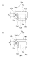
- 5A and 5B are explanatory diagrams of the actuator.
- FIG. 1 is a block diagram of a camera (imaging device) A provided with a focal plane shutter 1.
- the camera A includes a focal plane shutter 1, a control unit 110, an image sensor 130, and a drive control unit 170.
- the focal plane shutter 1 includes a first actuator (hereinafter referred to as an actuator) 70a, a second actuator (hereinafter referred to as an actuator) 70b, a first sensor (hereinafter referred to as a sensor) 60a, and a second sensor. 60b (hereinafter referred to as a sensor).
- the drive control unit 170 controls the driving of the actuators 70a and 70b in accordance with a command from the control unit 110.
- the drive control unit 170 includes a CPU and the like.
- the control unit 110 issues a predetermined command to the drive control unit 170 in accordance with signals from the sensors 60a and 60b. In response to this command, the drive control unit 170 controls the drive of the actuators 70a and 70b.
- the control unit 110 controls the operation of the entire camera and includes a CPU, a ROM, a RAM, and the like.
- the image sensor 130 is a CMOS.
- the image sensor 130 is a light receiving element that converts a subject image into an electrical signal by a photoelectric conversion action.
- the camera A includes a lens and the like for adjusting the focal length.
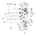
- FIG. 2 is a front view of the focal plane shutter 1.
- the actuators 70a and 70b are omitted.
- the focal plane shutter 1 includes a substrate 10, a front curtain 20A, a rear curtain 20B, arms 31a, 32a, 31b, 32b, actuators 70a, 70b, and the like.
- the substrate 10 has a rectangular opening 11.
- the front curtain 20A and the rear curtain 20B are examples of the first and second curtains, respectively.
- the actuators 70a and 70b are examples of first and second actuators, respectively.
- the front curtain 20A is composed of three blades 21a to 23a
- the rear curtain 20B is composed of three blades 21b to 23b.
- FIG. 2 shows a case where the front curtain 20A and the rear curtain 20B are in a superimposed state.
- the front curtain 20 ⁇ / b> A and the rear curtain 20 ⁇ / b> B are retracted from the opening 11.
- the front curtain 20A is connected to the arms 31a and 32a.
- the rear curtain 20B is connected to the arms 31b and 32b. These arms 31a, 32a, 31b, and 32b are rotatably supported by the substrate 10, respectively.
- the substrate 10 is provided with a first drive lever (hereinafter referred to as drive lever) 55a and a second drive lever (hereinafter referred to as drive lever) 55b for driving the arms 31a and 31b, respectively.
- the drive levers 55a and 55b are connected to gears 50a and 50b, respectively.
- the gears 50a and 50b mesh with the gears 40a and 40b, respectively.
- the gears 40a, 40b, 50a, and 50b have cylindrical portions 41a, 41b, 51a, and 51b, respectively, and are rotatably supported by the substrate 10 around shafts 42a, 42b, 52a, and 52b that are fitted to the cylindrical portions. ing.
- the shafts 42 a, 42 b, 52 a, 52 b do not necessarily have to be formed on the substrate 10 in which the opening 11 is formed, and may be provided at a fixed position with respect to the opening 11.
- Gears 40a and 40b are connected to rotors 72a and 72b of actuators 70a and 70b, which will be described later.
- the gears 40a and 50a are driven, thereby driving the drive lever 55a.
- the arm 31a is driven by driving the drive lever 55a.
- the leading curtain 20A travels.
- the front curtain 20 ⁇ / b> A can travel between a retracted position retracted from the opening 11 and a closed position closing the opening 11.
- the front curtain 20A travels between the retracted position and the closed position by the actuator 70a.
- the gears 40a and 40b are provided with thin plates 45a and 45b, respectively.
- the thin plates 45a and 45b rotate with the gears 40a and 40b, respectively.
- Each of the thin plates 45a and 45b has a fan shape.
- the sensors 60a and 60b detect the positions of the front curtain 20A and the rear curtain 20B by detecting whether or not the thin plates 45a and 45b have passed the sensors 60a and 60b, respectively.
- springs Sa and Sb are connected to the arms 31a and 31b, respectively. Specifically, one end of the spring Sa is connected to the arm 31 a and the other end is connected to the substrate 10. One end of the spring Sb is connected to the arm 31 b and the other end is connected to the substrate 10.
- the springs Sa and Sb bias the arms 31a and 31b so that the front curtain 20A and the rear curtain 20B are retracted from the opening 11, respectively.
- the springs Sa and Sb are examples of first and second urging members, respectively.
- FIG. 2 to 4 are explanatory diagrams of the operation of the focal plane shutter 1.
- FIG. 2 In the standby state, as shown in FIG. 2, the front curtain 20A and the rear curtain 20B are positioned at the retracted position, and the opening 11 is maintained in the fully opened state. In the standby state shown in FIG. 2, the front curtain 20A and the rear curtain 20B are maintained at positions retracted from the opening 11 by the springs Sa and Sb, respectively.
- Camera A can support a live view mode in which the output from the image sensor is displayed on a liquid crystal monitor or the like in real time. That is, the camera A is a digital camera. Accordingly, the state of FIG. 2 is maintained in the live view mode. Even when the actuators 70a and 70b are not energized, the state where the front curtain 20A and the rear curtain 20B are retracted from the opening 11 can be maintained by the springs Sa and Sb. Accordingly, for example, even when an impact is applied to the camera A in the live view mode, the leading curtain 20A and the trailing curtain 20B are prevented from proceeding to the opening 11.
- the charging operation is started.
- the coil of the actuator 70a is energized and the front curtain 20A travels so as to close the opening 11.
- the gear 40a rotates counterclockwise
- the gear 50a rotates clockwise
- the arm 31a is driven.
- the arm 31a moves so as to resist the biasing force of the spring Sa.
- FIG. 3 shows the state of the focal plane shutter 1 when the charging operation is completed.
- the front curtain 20A is in the closed position and the rear curtain 20B is in the retracted position.
- the control unit 110 issues a command to the drive control unit 170 to energize the coil of the actuator 70a so that the front curtain 20A opens the opening 11. Specifically, the gear 40a is driven clockwise and the gear 50a is driven counterclockwise. At this time, the arm 31a moves in the same direction as the biasing direction of the spring Sa, and the front curtain 20A travels. Control unit 110 can detect that front curtain 20 ⁇ / b> A has been retracted from opening 11 by detecting the switching of the output signal from sensor 60 a. When the front curtain 20A is retracted from the opening 11, the state shown in FIG.
- the control unit 110 detects that the front curtain 20A has retreated from the opening 11 by the sensor 60a and energizes the coil of the actuator 70b after a predetermined period of time to start running the rear curtain 20B.
- the arm 31b moves in a direction opposite to the biasing direction of the spring Sb, and the trailing curtain 20B travels. Accordingly, the rear curtain 20B travels so as to close the opening 11.
- FIG. 4 shows a state in which the front curtain 20A is in the retracted position and the rear curtain 20B is in the closed position. In this way, the exposure operation ends.
- control unit 110 starts energization of the coil of the actuator 70b and starts running of the rear curtain 20B after a predetermined period of time has elapsed after detecting that the traveling front curtain 20A has passed the predetermined position.
- the position where the front curtain 20A is retracted from the opening 11 by the sensor 60a is described as the predetermined position, but the present invention is not limited to this.
- the front curtain 20A is retracted from the opening 11 while being assisted by the biasing force of the spring Sa, and the rear curtain 20B is closed against the biasing force of the spring Sb. That is, in the exposure operation, the actuator 70a travels the front curtain 20A while being assisted by the spring Sa, while the actuator 70b travels the rear curtain 20B against the urging force of the spring Sb. For this reason, the load of the actuator 70a becomes smaller than the load of the actuator 70b. Therefore, even when the actuators 70a and 70b are driven under the same driving conditions, for example, by applying the same current value, if the photographing is repeated, the difference in the amount of heat generated between the actuators 70a and 70b increases.
- the operating speed of the front curtain 20A and the rear curtain 20B may change.
- a change in shutter speed accompanying a change in operating characteristics of the actuators 70a and 70b may cause a problem such as a reduction in image quality.
- the power value supplied to the actuator 70a and the power value supplied to the actuator 70b are set differently.
- the power value supplied to the actuator 70a may be set smaller than the power value supplied to the actuator 70b.
- the control by the drive control unit 170 may be complicated and costly.
- the drive torque of the actuator 70a is smaller than the drive torque of the actuator 70b, and the power supplied to the actuators 70a and 70b by the drive control unit 170 is set to be substantially the same.
- the actuator 70a includes a rotor 72a, a stator 74a in which a magnetic force acts between the rotor 72a when excited, and a coil 76a for exciting the stator 74a.
- the rotor 72a is a permanent magnet magnetized with different polarities in the circumferential direction.
- the rotor 72a is rotatably supported by the shaft 42a.
- a gear 40a is fixed to the rotor 72a, and the leading blade 20A is driven by the rotation of the rotor 72a.
- the actuator 70b includes a rotor 72b, a stator 74b, and a coil 76b.
- the rotor 72b is rotatably supported by the shaft 42b, and the gear 40b is fixed.
- the rear curtain 20B is driven by the rotation of the rotor 72b.
- the stator 74a includes a base portion 74a1 extending in a predetermined direction, leg portions 74a2 and 74a4 extending in a direction intersecting the base portion 74a1 from both ends of the base portion 74a1, and magnetic pole portions 74a3 and leg portions 74a4 formed at the tips of the leg portions 74a2.
- a coil bobbin 78a around which a coil 76a is wound is assembled to the leg 74a4.
- the magnetic pole portions 74a3 and 74a5 are opposed to the rotor 72a. Specifically, each of the magnetic pole portions 74a3 and 74a5 has a curved surface partially facing the outer peripheral surface of the rotor 72a.
- the magnetic pole portions 74a3 and 74a5 are excited to have different polarities by energization of the coil 76a. As a result, a magnetic force is generated between the magnetic pole portions 74a3 and 74a5 and the rotor 72a, and the rotor 72a rotates.
- the stator 74b includes a base portion 74b1, leg portions 74b2, 74b4, and magnetic pole portions 74b3, 74b5, and the rotor 72b rotates by energization of the coil 76b.
- the shapes of the stators 74a and 74b are different, but the rotors 72a and 72b and the coils 76a and 76b are the same.
- the number of turns of the coils 76a and 76b is also the same.
- the distance Wa between the tip of the magnetic pole part 74a3 and the tip of the magnetic pole part 74a5 is greater than the distance Wb between the tip of the magnetic pole part 74b3 and the tip of the magnetic pole part 74b5. Is also big.
- the area of the curved surface where the magnetic pole portions 74a3 and 74a5 are opposed to the rotor 72a is smaller than the area of the curved surface where the magnetic pole portions 74b3 and 74b5 are opposed to the rotor 72b.
- the driving torque of the actuator 70a is set smaller than the driving torque of the actuator 70b. Therefore, even if the springs Sa and Sb urge the front curtain 20A and the rear curtain 20B to retreat from the openings, respectively, and the power values supplied to the actuators 70a and 70b are the same, changes in the shutter speed can be suppressed.
- the driving torque of the actuator 70a may be made smaller than the driving torque of the actuator 70b.
- the area of the portion of the actuator 70b where the cross section of the magnetic path of the stator is minimized may be smaller than the area of the portion of the actuator 70b where the cross section of the magnetic path of the stator 74b is minimized.
- the number of turns of the actuator 70a may be smaller than the number of turns of the coil 76b.
- the linear shape and material of the coil of the actuator 70a may be different from that of the coil 76b.
- the size and material of the rotor of the actuator 70a may be different from that of the rotor 72b.
- control unit 110 and the drive control unit 170 may be realized by a single IC chip.
- the front curtain and the rear curtain are each composed of three blades, but are not limited thereto, and may be composed of, for example, two blades, or four or more blades. It may be composed of blades.
Landscapes
- Physics & Mathematics (AREA)
- General Physics & Mathematics (AREA)
- Engineering & Computer Science (AREA)
- Multimedia (AREA)
- Signal Processing (AREA)
- Shutters For Cameras (AREA)
- Studio Devices (AREA)
Priority Applications (3)
| Application Number | Priority Date | Filing Date | Title |
|---|---|---|---|
| KR1020147019595A KR101688708B1 (ko) | 2012-06-15 | 2013-02-08 | 초점면 셔터, 촬상 장치 및 디지털 카메라 |
| CN201380007547.8A CN104081273B (zh) | 2012-06-15 | 2013-02-08 | 焦平面快门、成像装置和数字照相机 |
| US14/325,716 US9395598B2 (en) | 2012-06-15 | 2014-07-08 | Focal plane shutter, imaging device and digital camera |
Applications Claiming Priority (2)
| Application Number | Priority Date | Filing Date | Title |
|---|---|---|---|
| JP2012-136062 | 2012-06-15 | ||
| JP2012136062A JP5991780B2 (ja) | 2012-06-15 | 2012-06-15 | フォーカルプレーンシャッタ、撮像装置、及びデジタルカメラ |
Related Child Applications (1)
| Application Number | Title | Priority Date | Filing Date |
|---|---|---|---|
| US14/325,716 Continuation US9395598B2 (en) | 2012-06-15 | 2014-07-08 | Focal plane shutter, imaging device and digital camera |
Publications (1)
| Publication Number | Publication Date |
|---|---|
| WO2013187083A1 true WO2013187083A1 (fr) | 2013-12-19 |
Family
ID=49757925
Family Applications (1)
| Application Number | Title | Priority Date | Filing Date |
|---|---|---|---|
| PCT/JP2013/053058 Ceased WO2013187083A1 (fr) | 2012-06-15 | 2013-02-08 | Obturateur de plan focal, dispositif d'imagerie et caméra numérique |
Country Status (5)
| Country | Link |
|---|---|
| US (1) | US9395598B2 (fr) |
| JP (1) | JP5991780B2 (fr) |
| KR (1) | KR101688708B1 (fr) |
| CN (1) | CN104081273B (fr) |
| WO (1) | WO2013187083A1 (fr) |
Families Citing this family (3)
| Publication number | Priority date | Publication date | Assignee | Title |
|---|---|---|---|---|
| JP6153362B2 (ja) * | 2013-03-27 | 2017-06-28 | セイコープレシジョン株式会社 | 撮像装置及びフォーカルプレーンシャッタ |
| JP6543932B2 (ja) * | 2015-01-07 | 2019-07-17 | セイコープレシジョン株式会社 | 羽根駆動装置および光学機器 |
| JP6341872B2 (ja) * | 2015-02-27 | 2018-06-13 | 日本電産コパル株式会社 | カメラ用フォーカルプレーンシャッタシステムおよびカメラ用フォーカルプレーンシャッタ |
Citations (6)
| Publication number | Priority date | Publication date | Assignee | Title |
|---|---|---|---|---|
| JPS5387128A (en) * | 1977-01-11 | 1978-08-01 | Canon Inc | Number display system of electronic apparatus |
| JPH0329837U (fr) * | 1989-07-28 | 1991-03-25 | ||
| JPH0720523A (ja) * | 1993-07-06 | 1995-01-24 | Canon Inc | カメラ |
| JP2005151637A (ja) * | 2003-11-12 | 2005-06-09 | Canon Inc | ステッピングモータ及び光量調節装置 |
| JP2006126515A (ja) * | 2004-10-28 | 2006-05-18 | Seiko Precision Inc | カメラ用シャッタ |
| JP2007286443A (ja) * | 2006-04-18 | 2007-11-01 | Canon Inc | 光学機器及び当該光学機器における異物除去方法 |
Family Cites Families (17)
| Publication number | Priority date | Publication date | Assignee | Title |
|---|---|---|---|---|
| JPS5950045B2 (ja) | 1977-01-11 | 1984-12-06 | 日本電産コパル株式会社 | フオ−カルプレンシヤツタ |
| JPS58118628A (ja) * | 1982-01-07 | 1983-07-14 | Canon Inc | 電磁制御シヤツタ− |
| JP2735626B2 (ja) | 1989-06-28 | 1998-04-02 | キリンビバレッジ株式会社 | 微生物の迅速測定装置 |
| JP2592209Y2 (ja) * | 1993-03-12 | 1999-03-17 | セイコープレシジョン株式会社 | フォーカルプレーンシャッタの駆動機構 |
| JP3682511B2 (ja) * | 1996-08-28 | 2005-08-10 | キヤノン電子株式会社 | シャッター装置およびこれを備えたカメラ |
| JPH11258656A (ja) * | 1998-03-10 | 1999-09-24 | Copal Co Ltd | カメラ用フォーカルプレンシャッタ |
| JP2000284339A (ja) | 1999-03-31 | 2000-10-13 | Nidec Copal Corp | カメラ用シャッタ装置 |
| JP2001264846A (ja) * | 2000-03-21 | 2001-09-26 | Canon Electronics Inc | フォーカルプレーンシャッタおよびこれを備えたカメラ |
| JP4357715B2 (ja) | 2000-07-24 | 2009-11-04 | 東京エレクトロン株式会社 | 熱処理装置の温度校正方法 |
| JP2003005252A (ja) * | 2001-06-25 | 2003-01-08 | Nidec Copal Corp | カメラ用シャッタ装置 |
| JP4077709B2 (ja) * | 2002-10-16 | 2008-04-23 | 日本電産コパル株式会社 | デジタルスチルカメラ用フォーカルプレンシャッタ |
| JP2005304221A (ja) * | 2004-04-14 | 2005-10-27 | Canon Electronics Inc | 駆動装置及びシャッター装置 |
| US20070172231A1 (en) | 2006-01-26 | 2007-07-26 | Melles Griot, Inc. | Rotor magnet driven optical shutter assembly |
| JP4869855B2 (ja) * | 2006-10-04 | 2012-02-08 | セイコープレシジョン株式会社 | 電磁アクチュエータ及びカメラ用羽根駆動装置 |
| JP2008225140A (ja) * | 2007-03-14 | 2008-09-25 | Fujifilm Corp | レンズ移動装置及びデジタルカメラ |
| KR101798181B1 (ko) * | 2010-08-05 | 2017-11-17 | 삼성전자주식회사 | 셔터 장치 및 그를 구비한 이미지 캡쳐 장치 |
| JP3176166U (ja) * | 2012-03-29 | 2012-06-14 | セイコープレシジョン株式会社 | フォーカルプレーンシャッタ及び撮像装置 |
-
2012
- 2012-06-15 JP JP2012136062A patent/JP5991780B2/ja active Active
-
2013
- 2013-02-08 KR KR1020147019595A patent/KR101688708B1/ko not_active Expired - Fee Related
- 2013-02-08 WO PCT/JP2013/053058 patent/WO2013187083A1/fr not_active Ceased
- 2013-02-08 CN CN201380007547.8A patent/CN104081273B/zh active Active
-
2014
- 2014-07-08 US US14/325,716 patent/US9395598B2/en active Active
Patent Citations (6)
| Publication number | Priority date | Publication date | Assignee | Title |
|---|---|---|---|---|
| JPS5387128A (en) * | 1977-01-11 | 1978-08-01 | Canon Inc | Number display system of electronic apparatus |
| JPH0329837U (fr) * | 1989-07-28 | 1991-03-25 | ||
| JPH0720523A (ja) * | 1993-07-06 | 1995-01-24 | Canon Inc | カメラ |
| JP2005151637A (ja) * | 2003-11-12 | 2005-06-09 | Canon Inc | ステッピングモータ及び光量調節装置 |
| JP2006126515A (ja) * | 2004-10-28 | 2006-05-18 | Seiko Precision Inc | カメラ用シャッタ |
| JP2007286443A (ja) * | 2006-04-18 | 2007-11-01 | Canon Inc | 光学機器及び当該光学機器における異物除去方法 |
Also Published As
| Publication number | Publication date |
|---|---|
| CN104081273A (zh) | 2014-10-01 |
| KR20140102306A (ko) | 2014-08-21 |
| US20140320737A1 (en) | 2014-10-30 |
| JP2014002208A (ja) | 2014-01-09 |
| KR101688708B1 (ko) | 2016-12-21 |
| CN104081273B (zh) | 2016-09-28 |
| US9395598B2 (en) | 2016-07-19 |
| JP5991780B2 (ja) | 2016-09-14 |
Similar Documents
| Publication | Publication Date | Title |
|---|---|---|
| CN105723278B (zh) | 快门装置及包括快门装置的摄像设备 | |
| WO2013094278A1 (fr) | Obturateur focal et appareil optique muni de cet obturateur | |
| JP2012208280A (ja) | 撮像装置 | |
| US9395599B2 (en) | Focal plane shutter and optical apparatus | |
| JP5991780B2 (ja) | フォーカルプレーンシャッタ、撮像装置、及びデジタルカメラ | |
| US9513533B2 (en) | Focal plane shutter and optical apparatus provided with same | |
| US9304374B2 (en) | Focal-plane shutter, optical device, and method for adjusting current for focal-plane shutter | |
| JP6063324B2 (ja) | 撮像装置及びフォーカルプレーンシャッタ | |
| JP5328187B2 (ja) | 羽根駆動装置および撮像装置 | |
| US9436063B2 (en) | Blade driving device and optical apparatus | |
| JP7038108B2 (ja) | フォーカルプレンシャッタ及びこれを備える撮像装置 | |
| CN105765455B (zh) | 图像拾取装置和焦平面快门 | |
| JP3176166U (ja) | フォーカルプレーンシャッタ及び撮像装置 | |
| JP2020067581A (ja) | フォーカルプレンシャッタ、及び撮像装置 | |
| JP2019015784A (ja) | フォーカルプレンシャッタ及び撮像装置 | |
| JP2016136202A (ja) | 羽根駆動装置及び撮像装置 | |
| JP2008116641A (ja) | カメラ用シャッタ装置 |
Legal Events
| Date | Code | Title | Description |
|---|---|---|---|
| 121 | Ep: the epo has been informed by wipo that ep was designated in this application |
Ref document number: 13803429 Country of ref document: EP Kind code of ref document: A1 |
|
| ENP | Entry into the national phase |
Ref document number: 20147019595 Country of ref document: KR Kind code of ref document: A |
|
| NENP | Non-entry into the national phase |
Ref country code: DE |
|
| 122 | Ep: pct application non-entry in european phase |
Ref document number: 13803429 Country of ref document: EP Kind code of ref document: A1 |