WO2013187111A1 - Embrayage à griffes - Google Patents
Embrayage à griffes Download PDFInfo
- Publication number
- WO2013187111A1 WO2013187111A1 PCT/JP2013/060743 JP2013060743W WO2013187111A1 WO 2013187111 A1 WO2013187111 A1 WO 2013187111A1 JP 2013060743 W JP2013060743 W JP 2013060743W WO 2013187111 A1 WO2013187111 A1 WO 2013187111A1
- Authority
- WO
- WIPO (PCT)
- Prior art keywords
- rotating body
- torque receiving
- groove
- side rotating
- gear
- Prior art date
- Legal status (The legal status is an assumption and is not a legal conclusion. Google has not performed a legal analysis and makes no representation as to the accuracy of the status listed.)
- Ceased
Links
Images








Classifications
-
- F—MECHANICAL ENGINEERING; LIGHTING; HEATING; WEAPONS; BLASTING
- F16—ENGINEERING ELEMENTS AND UNITS; GENERAL MEASURES FOR PRODUCING AND MAINTAINING EFFECTIVE FUNCTIONING OF MACHINES OR INSTALLATIONS; THERMAL INSULATION IN GENERAL
- F16D—COUPLINGS FOR TRANSMITTING ROTATION; CLUTCHES; BRAKES
- F16D11/00—Clutches in which the members have interengaging parts
- F16D11/14—Clutches in which the members have interengaging parts with clutching members movable only axially
-
- F—MECHANICAL ENGINEERING; LIGHTING; HEATING; WEAPONS; BLASTING
- F16—ENGINEERING ELEMENTS AND UNITS; GENERAL MEASURES FOR PRODUCING AND MAINTAINING EFFECTIVE FUNCTIONING OF MACHINES OR INSTALLATIONS; THERMAL INSULATION IN GENERAL
- F16D—COUPLINGS FOR TRANSMITTING ROTATION; CLUTCHES; BRAKES
- F16D11/00—Clutches in which the members have interengaging parts
- F16D11/08—Clutches in which the members have interengaging parts actuated by moving a non-rotating part axially
- F16D11/10—Clutches in which the members have interengaging parts actuated by moving a non-rotating part axially with clutching members movable only axially
-
- F—MECHANICAL ENGINEERING; LIGHTING; HEATING; WEAPONS; BLASTING
- F16—ENGINEERING ELEMENTS AND UNITS; GENERAL MEASURES FOR PRODUCING AND MAINTAINING EFFECTIVE FUNCTIONING OF MACHINES OR INSTALLATIONS; THERMAL INSULATION IN GENERAL
- F16D—COUPLINGS FOR TRANSMITTING ROTATION; CLUTCHES; BRAKES
- F16D21/00—Systems comprising a plurality of actuated clutches
- F16D21/02—Systems comprising a plurality of actuated clutches for interconnecting three or more shafts or other transmission members in different ways
- F16D21/04—Systems comprising a plurality of actuated clutches for interconnecting three or more shafts or other transmission members in different ways with a shaft carrying a number of rotatable transmission members, e.g. gears, each of which can be connected to the shaft by a clutching member or members between the shaft and the hub of the transmission member
-
- F—MECHANICAL ENGINEERING; LIGHTING; HEATING; WEAPONS; BLASTING
- F16—ENGINEERING ELEMENTS AND UNITS; GENERAL MEASURES FOR PRODUCING AND MAINTAINING EFFECTIVE FUNCTIONING OF MACHINES OR INSTALLATIONS; THERMAL INSULATION IN GENERAL
- F16D—COUPLINGS FOR TRANSMITTING ROTATION; CLUTCHES; BRAKES
- F16D11/00—Clutches in which the members have interengaging parts
- F16D2011/008—Clutches in which the members have interengaging parts characterised by the form of the teeth forming the inter-engaging parts; Details of shape or structure of these teeth
-
- F—MECHANICAL ENGINEERING; LIGHTING; HEATING; WEAPONS; BLASTING
- F16—ENGINEERING ELEMENTS AND UNITS; GENERAL MEASURES FOR PRODUCING AND MAINTAINING EFFECTIVE FUNCTIONING OF MACHINES OR INSTALLATIONS; THERMAL INSULATION IN GENERAL
- F16D—COUPLINGS FOR TRANSMITTING ROTATION; CLUTCHES; BRAKES
- F16D2300/00—Special features for couplings or clutches
- F16D2300/10—Surface characteristics; Details related to material surfaces
Definitions
- the present invention relates to a meshing clutch suitable for a gear reducer.
- a meshing clutch called a dog clutch or a jaw clutch is used for the gear reducer. That is, the meshing clutch is provided with a convex portion on one of the driving side rotating body and the driven side rotating body, a concave portion on the other side, the driving side rotating body is rotated, and the driving side rotating body is meshed with the convex portion.
- This is a power transmission mechanism of a type that transmits a driving force from the rotating body to the driven side rotating body.
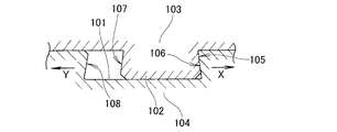
- FIG. 16 shows a dog clutch disclosed in Patent Document 1.
- the convex portion 102 is fitted into the concave portion 101.
- the convex portion 102 is formed on the driving side rotating body 103 and the concave portion 101 is formed on the driven side rotating body 104
- the driving side rotating body 103 moves in the direction of the arrow X
- the side surface 105 of the convex portion 102 is changed.
- the driven side rotating body 104 also moves in the direction of arrow X.
- the driving side rotating body 103 moves in the direction of arrow Y
- the side surface 107 of the convex portion 102 hits the receiving surface 108 of the concave portion 101, and then the driven side rotating body 104 also moves in the direction of arrow Y.
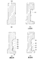
- the dog clutch disclosed in Patent Document 1 does not describe a manufacturing method of the recess 101, but is generally formed by a cutting method. Therefore, an outline of the cutting method will be described with reference to FIG.
- a material 109 is prepared.
- a concave portion 101 shown in FIG. 17B is cut and formed on the material 109 by an end mill or a milling cutter.
- “ ⁇ ” means a finish symbol.
- a large amount of chips are generated by cutting. Since the cutting time increases as the amount of chips increases, the number of processing steps increases. In addition, waste of material occurs due to a large amount of chips. While it is required to reduce the product cost, it is required to shorten the cutting time and reduce the amount of chips.
- An object of the present invention is to provide a meshing clutch that can shorten the cutting time and generate less chips.
- the convex portion is provided on one of the driving side rotating body and the driven side rotating body, the concave portion is provided on the other, the convex portion is engaged with the concave portion, and the torque receiving surface of the concave portion is engaged.
- the concave portion has a strip-shaped island portion protruding from the bottom surface in the circumferential direction.
- the groove portion and the bottom surface are formed by a forging die, the surface is a forged black skin, and the island portion is the forged metal
- a cutting surface formed by cutting an upper portion after being molded by the mold and receiving a tip end surface of the convex portion; the groove portion is formed to be deeper than the bottom surface; and the cutting surface is the bottom surface Shallow mesh that is formed shallower Chi is provided.
- the strip-shaped island portion extending in the circumferential direction has one end and the other end formed in a semicircular shape.
- the drive-side rotator has a gear portion formed on an outer peripheral side of the concave portion, and the concave portion is an outer edge continuous with the torque receiving surface formed in a circumferential direction.
- the outer edge portion and the inner edge portion have an arcuate substantially trapezoidal shape, and the outer edge portion is formed on the bottom surface of the bottom surface.
- An arc surface formed with a radius corresponding to or greater than the depth is continuous with the bottom surface.
- the radius of the arc surface formed between the outer edge portion and the torque receiving surface is larger than the radius of the arc surface formed between the inner edge portion and the torque receiving surface. Is also big.
- the bottom surface constituting the recess and the groove portion directly below the torque receiving surface remain forged black skin.
- the strip-shaped island portion protruding from the bottom surface is cut at the top after forging. If most of the concave portions remain forged, chip generation is small and the cutting time is short.
- the meshing clutch which can shorten cutting processing time and can generate
- the bottom surface constituting the recess was made shallower than the groove. If the bottom surface has the same depth as the groove portion, the recess becomes deeper as a whole, and the protruding length of the forging die increases. The longer the protrusion length, the greater the stress generated in the forging die during forging, so the life of the forging die is shortened. Further, the product thickness of the driving side rotating body or the driven side rotating body becomes smaller as the concave portion becomes deeper. Since the concave portion is deep, the product thickness is reduced, and the strength of the driving side rotating body or the driven side rotating body is lowered. In this regard, according to the present invention, the bottom surface is shallower than the groove.
- the recesses become shallow. Then, the protrusion length of a forging die becomes short, the stress which generate
- both ends in the circumferential direction of the strip-shaped island part are semicircular.
- An island forming groove for forming an island is provided in the forging die. Since this groove has a semicircular shape at both ends, it is easy to process with an end mill. That is, the island-forming grooves can be engraved in one pass by an end mill having an outer diameter corresponding to the width of the groove, and the number of steps for forming the island-forming grooves of the forging die can be reduced. Further, since both ends of the island forming groove are semicircular, stress concentration is avoided and the life of the forging die can be further extended.
- the concave portion has a substantially trapezoidal shape, and the outer edge portion is continuous with the bottom surface by an arc surface having a radius corresponding to or larger than the depth of the bottom surface in a cross-sectional view.
- Protrusion for bottom surface formation is provided on the forging die. By providing an arcuate surface having a large radius on this bottom surface formation protrusion, the durability of the bottom surface formation protrusion can be enhanced and the life of the forging die is further extended. be able to.
- a gear portion is formed on the outer periphery of the recess, and even if a large torque is transmitted to the gear portion, the stress concentration is greatly relieved by the arc surface having a large radius, so there is a concern that the meshing clutch may be broken. Absent.
- the radius of the arc surface formed between the outer edge portion and the torque receiving surface is larger than the radius of the arc surface formed between the inner edge portion and the torque receiving surface. That is, the circular arc surface is composed of a large radius and a small radius. Even if torque is transmitted to the gear on the outer periphery of the driving side rotating body, since the radius of the arc surface between the outer edge portion and the torque receiving surface is large, the stress concentration is greatly relieved and there is no fear that the meshing clutch is broken. On the other hand, since the radius of the circular arc surface formed between the inner edge portion and the torque receiving surface is a portion far from the gear, a small radius may be used. If the radius of the circular arc surface formed between the inner edge portion and the torque receiving surface is small, the degree of freedom in designing the shape of the meshing clutch increases.
- FIG. 6 is a cross-sectional view taken along line 6-6 in FIG. It is the figure which showed the meshing clutch. It is the figure which showed the manufacturing method of the meshing clutch.
- FIG. 9 is a cross-sectional view taken along line 9-9 in FIG. It is the figure which showed the manufacturing method by the cross section of a meshing clutch.
- FIG. 5 is a cross-sectional view taken along line 11-11 in FIG.
- FIG. 14 is a cross-sectional view taken along line 14-14 of FIG. It is the figure which showed the example of a change of the manufacturing method of the meshing clutch shown in FIG. It is sectional drawing of the conventional dog clutch. It is the figure which showed the manufacturing method of the conventional dog clutch.
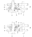
- the gear transmission 10 includes a drive shaft 11 and a driven shaft 12.
- the first gear 13 and the second gear 14 having a larger diameter than the first gear 13 are integrally attached to the drive shaft 11 by press fitting.
- the third gear 16 as a drive side rotating body is rotatably attached to the driven shaft 12 via the needle bearing 15.
- the third gear 16 has a recess 17 on one side in the axial direction, and always meshes with the first gear 13.
- the fourth gear 18 is rotatably attached to the driven shaft 12 via the needle bearing 15.
- the fourth gear 18 has a recess 19 on one side in the axial direction, and always meshes with the second gear 14.
- the cylindrical guide 21 is fitted to the driven shaft 12 so as to be sandwiched between the third gear 16 and the fourth gear 18.
- a driven-side rotating body 23 is attached to the cylindrical guide 21 via a spline 22 so that the shaft can move freely.
- the driven-side rotator 23 has convex portions 24 and 24 on one side and the other side in the axial direction, and an annular groove 25 on the outer periphery.
- a shift fork 26 is fitted in the annular groove 25.
- the meshing clutch 20 is configured by the third gear 16 that is the driving side rotating body and the driven side rotating body 23. Since it is a clutch, it is connected to the power system to disconnect / connect the power. The power disconnection / connection will be described below.
- the driven rotor 23 is normally in a so-called neutral position.
- the third gear 16 is rotated by the first gear 13 and the fourth gear 18 is rotated by the second gear 14. 12 is not rotated.
- the convex portion 24 provided on the other side in the axial direction of the driven-side rotating body 23 is the fourth.
- the protrusion 24 provided on one side in the axial direction of the driven-side rotating body 23 engages with the recess 17 of the third gear 16.
- the fourth gear 18 and the driven side rotating body 23 are mechanically coupled. Then, the driven shaft 12 is rotated by the drive shaft 11 via the second gear 14 and the fourth gear 18. If it is FIG.2 (b), the 3rd gear 16 and the driven side rotary body 23 will be mechanically connected. Then, the driven shaft 12 is rotated by the drive shaft 11 via the first gear 13 and the third gear 16. Since the first gear 13 and the second gear 14 have different diameters, the rotational speed of the driven shaft 12 is different in FIGS. 2 (a) and 2 (b). That is, shifting can be performed by the shift fork 26.
- the drive shaft 11 and the driven shaft 12 can be interchanged. That is, the reference number 12 can be a drive shaft, the reference number 11 can be a driven shaft, the reference number 23 can be a drive side rotating body, and the reference number 16 can be a driven side rotating body.
- the convex portion 24 may be provided on one of the driving side rotating body (third gear 16) and the driven side rotating body 23, and the concave portion 17 may be provided on the other side.
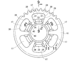
- the driven-side rotating body 23 has splines 22 on the inner peripheral surface, and a plurality of (in this example, six) convex portions on the side surface, which is the front surface of the drawing, at an equal pitch. 24 with a ring.
- the third gear 16 has a plurality of (six in this example) recesses 17.
- the outer edge portion 28 is longer than the inner edge portion 29, and the outer edge portion 28 and the inner edge portion 29 have an arcuate substantially trapezoidal shape centering on the rotation center.
- Torque receiving surfaces 31 and 31 are legs that connect both ends of the outer edge portion 28 and the inner edge portion 29 via a large-diameter arc 39 and a small-diameter arc 40 having a smaller radius of curvature than the large-diameter arc 39.
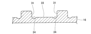
- the concave portion 17 has, on the bottom surface 32, a strip-shaped island portion 33 that protrudes from the bottom surface 32 to the drawing table and extends in the circumferential direction. In between, there are grooves 34 and 34 that are recessed from the bottom surface 32 toward the back of the drawing.
- the strip-shaped island portion 33 includes semicircular portions 35 and 35 at both ends in the circumferential direction.
- the groove portions 34, 34 are provided between the island portion 33 and the torque receiving surfaces 31, 31.
- the convex portion 24 of the driven-side rotator 23 is fitted in the concave portion 17 of the third gear 16, and the tip of the convex portion 24 slides along the island portion 33.
- the side surface 27 of 24 hits the torque receiving surface 31 of the recess 17.
- the base corner 101a of the recess 101 is a (radius) arc surface having a general tolerance of about 0.2 to 0.5 mm in the case of cutting.
- the arc surface of the tip corner 102 a of the projection 102 is set larger than the radius of curvature of the root corner 101 a of the recess 101.
- the length of the torque receiving surface 106 in the axial direction is ensured by making the curvature radius of the root corner 101a of the recess 101 smaller than 1 mm or less.
- the tip end corner of the convex portion of the forging die for forging the arc surface of the root corner 101a must have a radius of curvature smaller than 1 mm.
- the convex tip end corner of the forging die smaller than 1 mm is not preferred because stress concentrates during forging, and the convex tip corner of the forging die tends to break.
- the tip corner 24a of the convex portion 24 does not interfere with the root corner of the concave portion 17, and is necessary in the axial direction.
- the torque receiving surface 31 is ensured, and the side surface 27 of the convex portion 24 reliably hits the torque receiving surface 31, and torque is transmitted from the driving side rotating body (third gear 16) to the driven side rotating body 23.
- the curvature radius in the groove part 34 is enlarged as 1 mm or more (preferably 1.5 mm or more), the convex part front-end corner of a forging die will become difficult to break.
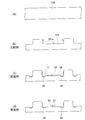
- a material 109 is prepared, and a recess 101 as shown in FIG. 8B is formed by cutting. “ ⁇ ” indicates a finished surface.
- the material 109 is prepared in FIG. 8A, and the concave portion 17 is formed by a plastic working method using a forging die (detailed later) as shown in FIG. 8C. To do. At this stage, the surfaces of the groove portions 34 and 34 and the island portion 33 are forged black skin. " ⁇ " Indicates forged black skin.
- the cutting allowance 36 is estimated in advance on the upper part of the island part 33, and the upper part of the island part 33 is cut with a milling cutter. Therefore, as shown in FIG. 8D, a cutting surface 37 is formed on the upper portion of the island portion 33. The other portions of the bottom surface 32 and the groove 34 remain forged black skin. Compared with FIG. 8B, FIG. 8D shows that the amount of cutting waste generated is significantly smaller.
- the island portion 33 protrudes from the bottom surface 32 in the concave portion 17.
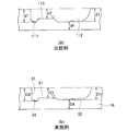
- the outer edge portion 28 continues to the bottom surface 32 by a circular arc surface 38 drawn with a radius R corresponding to the depth D1 of the bottom surface 32 or a radius R larger than that in the cross-sectional view.
- FIG. 10B shows a conventional comparative example
- FIGS. 10C and 10D show examples.
- FIG. 10A is prepared, and a recess 101 as shown in FIG. 10B is formed by cutting. “ ⁇ ” indicates a finished surface.
- the material 109 is prepared in FIG. 10A, and the concave portion 17 is formed by using a forging die (detailed later) as shown in FIG. 10C.
- the surfaces of the bottom surfaces 32 and 32, the island portion 33, and the groove portion 34 are forged black skin.
- the symbol “ ⁇ ” indicates forged black skin.
- a cutting allowance 36 is estimated in advance on the upper portion of the island portion 33, and the upper portion of the island portion 33 is cut with a milling cutter.
- FIG. 10 (d) a cutting surface 37 is formed on the upper portion of the island portion 33.
- the other portions of the bottom surface 32 and the groove 34 remain forged black skin.
- FIG. 10 (d) significantly reduces the amount of cutting waste generated and the cutting time.
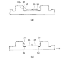
- FIG. 11A shows a comparative example
- FIG. 11B shows an example.
- the groove 111 and the bottom surface 112 have the same depth d1, and the depth d2 of the cutting surface 113 is smaller than d1. Since the bottom surface 112 has the largest area ratio, the bottom surface 112 is shown wide.
- the groove 34 is deepened (D1 ⁇ D2) and the cutting surface 37 is shallow (D3 ⁇ D1) with respect to the depth D1 of the bottom surface 32. Since the bottom surface 32 has the largest area ratio, the bottom surface 32 is shown wide.
- the product thickness D4 in (b) increases (d4 ⁇ D4).
- the greater the product thickness D4 the greater the strength of the third gear 16 as the drive side rotating body.
- a forging die (groove portion forming projection 52 to be described later) for forging the groove portion 34 has a length for extruding the material 109 to the forging die for forming the bottom portion 32.
- the stress is concentrated because it is longer than (the bottom surface forming projection 51 described later), but if the curvature radius of the bottom of the groove 34 is 1 mm or more (preferably 1.5 mm or more), the stress concentration is reduced.
- the groove 34 is deeper than the bottom surface 32, so that the convex portion 24 (sliding on the cutting surface 37)
- the tip of FIG. 7A is prevented from interfering with the groove portion 34, and the side surface 27 of the convex portion 24 reliably contacts the torque receiving surface 31 of the concave portion 37.
- the forging die 50 is provided with a bottom surface forming protrusion 51, and the bottom surface forming protrusion 51 is provided with groove portion forming protrusions 52, 52, and between these groove portion forming protrusions 52, 52.
- the bottom surface forming projection 51 is provided with an island forming groove 53.
- the island-forming grooves 53 are semicircular at both ends in the circumferential direction.
- a semi-circle can be formed at both ends simply by performing one-pass processing with an end mill 54 having an outer diameter corresponding to the groove width W of the island-forming groove 53. Therefore, the time required for forming the island portion forming groove 53 of the forging die 50 can be shortened. Moreover, since both ends of the island-forming groove 53 are semicircular, concentration of stress can be avoided and the life of the forging die 50 can be further extended.
- the durability of the bottom surface forming projection 51 can be improved.
- the life of the forging die 50 can be further extended.
- the torque receiving surface 31 is forged with the recess 17 having the allowance for the cutting allowance 36b.
- the machining allowance 36 and the machining allowance 36b are deleted by cutting. Accordingly, as shown in FIG. 15B, the drive-side rotating body 16 is obtained in which the upper surface of the island portion 33 is the cutting surface 37 and the torque receiving surface 31 is a finished surface.
- the drive side rotary body 16 of this invention was applied to the gear incorporated in a gear transmission in the Example.
- the drive side rotator 16 may be a rotator constituting a meshing clutch called a dog clutch or a jaw clutch, and is not limited to a gear.
- the present invention is suitable for a meshing clutch called a dog clutch or a jaw clutch.
Landscapes
- Engineering & Computer Science (AREA)
- General Engineering & Computer Science (AREA)
- Mechanical Engineering (AREA)
- Mechanical Operated Clutches (AREA)
Priority Applications (2)
| Application Number | Priority Date | Filing Date | Title |
|---|---|---|---|
| US14/406,818 US9518613B2 (en) | 2012-06-15 | 2013-04-09 | Dog clutch |
| EP13804036.5A EP2863085B1 (fr) | 2012-06-15 | 2013-04-09 | Embrayage à griffes |
Applications Claiming Priority (2)
| Application Number | Priority Date | Filing Date | Title |
|---|---|---|---|
| JP2012-136057 | 2012-06-15 | ||
| JP2012136057A JP5250137B1 (ja) | 2012-06-15 | 2012-06-15 | 噛み合いクラッチ |
Publications (1)
| Publication Number | Publication Date |
|---|---|
| WO2013187111A1 true WO2013187111A1 (fr) | 2013-12-19 |
Family
ID=49041912
Family Applications (1)
| Application Number | Title | Priority Date | Filing Date |
|---|---|---|---|
| PCT/JP2013/060743 Ceased WO2013187111A1 (fr) | 2012-06-15 | 2013-04-09 | Embrayage à griffes |
Country Status (4)
| Country | Link |
|---|---|
| US (1) | US9518613B2 (fr) |
| EP (1) | EP2863085B1 (fr) |
| JP (1) | JP5250137B1 (fr) |
| WO (1) | WO2013187111A1 (fr) |
Families Citing this family (3)
| Publication number | Priority date | Publication date | Assignee | Title |
|---|---|---|---|---|
| JP6177270B2 (ja) * | 2015-03-25 | 2017-08-09 | 株式会社豊田中央研究所 | 係合装置及び自動変速機 |
| JP6379284B2 (ja) * | 2015-04-01 | 2018-08-22 | 本田技研工業株式会社 | ドグ式クラッチ機構 |
| IT201700031648A1 (it) * | 2017-03-22 | 2018-09-22 | Piaggio & C Spa | Cambio di trasmissione per un motoveicolo e relativo motoveicolo che comprende detto cambio di trasmissione |
Citations (14)
| Publication number | Priority date | Publication date | Assignee | Title |
|---|---|---|---|---|
| US2049127A (en) * | 1932-07-30 | 1936-07-28 | Maybach Motorenbau Gmbh | Claw coupling |
| DE700712C (de) * | 1938-07-19 | 1940-12-27 | Maybach Motorenbau G M B H | Ausbildung von Klauenkupplungszaehnen, insbesondere bei Getrieben von Kraftfahrzeugen |
| US2558203A (en) * | 1945-08-04 | 1951-06-26 | Gleason Works | Clutch tooth |
| JPS3728816Y1 (fr) * | 1960-02-17 | 1962-10-25 | ||
| JPS5217706U (fr) * | 1975-06-27 | 1977-02-08 | ||
| US4909364A (en) * | 1988-05-12 | 1990-03-20 | Sundstrand Corporation | Latching failure detection mechanism for rotary drive systems |
| JPH0552362U (ja) * | 1991-12-24 | 1993-07-13 | セイレイ工業株式会社 | クイックヒッチ正逆転両用構造 |
| US5273499A (en) * | 1989-07-14 | 1993-12-28 | Zahnradfabrik Friedrichshafen Ag | Claw coupling with large angle of deflection and small retaining and releasing force |
| JPH0679395A (ja) * | 1992-08-18 | 1994-03-22 | Kawasaki Heavy Ind Ltd | 爪付きクラッチ部材の製造方法 |
| JPH1137173A (ja) * | 1997-07-18 | 1999-02-09 | Mitsubishi Agricult Mach Co Ltd | 双方向伝動ドッグクラッチ |
| JP2005048820A (ja) * | 2003-07-31 | 2005-02-24 | Yamaha Marine Co Ltd | 船外機用クラッチ装置 |
| JP2007205527A (ja) * | 2006-02-06 | 2007-08-16 | Aisin Seiki Co Ltd | クラッチディスク |
| JP2009190653A (ja) * | 2008-02-18 | 2009-08-27 | Yamaha Motor Co Ltd | 船舶推進機のシフト機構 |
| US20100140042A1 (en) * | 2005-07-20 | 2010-06-10 | Mack Trucks, Inc | Dog-tooth-face interface |
Family Cites Families (12)
| Publication number | Priority date | Publication date | Assignee | Title |
|---|---|---|---|---|
| DE599714C (de) * | 1932-07-31 | 1934-07-07 | Maybach Motorenbau G M B H | Ausbildung von Klauenkupplungszaehnen, insbesondere bei Getrieben von Kraftfahrzeugen |
| DE1159867B (de) * | 1959-06-20 | 1963-12-19 | Fein C & E | Schlagschrauber mit drehmomentabhaengiger Abschaltung des insbesondere elektromotorischen Antriebs |
| JPS5217706A (en) | 1975-08-01 | 1977-02-09 | Hitachi Ltd | Campon system of automaic exchange machine |
| JPS5997322A (ja) * | 1982-11-25 | 1984-06-05 | Kawasaki Heavy Ind Ltd | クラツチ爪を有するクラツチ部材およびクラツチ爪の加工方法 |
| JPH0552362A (ja) | 1991-08-22 | 1993-03-02 | Sanyo Electric Co Ltd | 空気調和装置 |
| JP4170534B2 (ja) * | 1999-09-03 | 2008-10-22 | 本田技研工業株式会社 | 変速機 |
| FR2820792B1 (fr) * | 2001-02-12 | 2003-04-04 | Peugeot Citroen Automobiles Sa | Dispositif de transmission de couple |
| JP2003301859A (ja) * | 2002-04-12 | 2003-10-24 | Yamaha Motor Co Ltd | 自動二輪車用変速機のドッグクラッチ |
| JP4805092B2 (ja) * | 2006-10-25 | 2011-11-02 | 本田技研工業株式会社 | 多板式クラッチ装置 |
| JP4979405B2 (ja) * | 2007-02-09 | 2012-07-18 | ヤマハ発動機株式会社 | 船外機 |
| JP5061388B2 (ja) * | 2008-02-29 | 2012-10-31 | 本田技研工業株式会社 | ドグクラッチ及び変速機 |
| JP5600441B2 (ja) * | 2010-02-12 | 2014-10-01 | 本田技研工業株式会社 | ドグクラッチ用ギヤ |
-
2012
- 2012-06-15 JP JP2012136057A patent/JP5250137B1/ja active Active
-
2013
- 2013-04-09 EP EP13804036.5A patent/EP2863085B1/fr active Active
- 2013-04-09 WO PCT/JP2013/060743 patent/WO2013187111A1/fr not_active Ceased
- 2013-04-09 US US14/406,818 patent/US9518613B2/en active Active
Patent Citations (14)
| Publication number | Priority date | Publication date | Assignee | Title |
|---|---|---|---|---|
| US2049127A (en) * | 1932-07-30 | 1936-07-28 | Maybach Motorenbau Gmbh | Claw coupling |
| DE700712C (de) * | 1938-07-19 | 1940-12-27 | Maybach Motorenbau G M B H | Ausbildung von Klauenkupplungszaehnen, insbesondere bei Getrieben von Kraftfahrzeugen |
| US2558203A (en) * | 1945-08-04 | 1951-06-26 | Gleason Works | Clutch tooth |
| JPS3728816Y1 (fr) * | 1960-02-17 | 1962-10-25 | ||
| JPS5217706U (fr) * | 1975-06-27 | 1977-02-08 | ||
| US4909364A (en) * | 1988-05-12 | 1990-03-20 | Sundstrand Corporation | Latching failure detection mechanism for rotary drive systems |
| US5273499A (en) * | 1989-07-14 | 1993-12-28 | Zahnradfabrik Friedrichshafen Ag | Claw coupling with large angle of deflection and small retaining and releasing force |
| JPH0552362U (ja) * | 1991-12-24 | 1993-07-13 | セイレイ工業株式会社 | クイックヒッチ正逆転両用構造 |
| JPH0679395A (ja) * | 1992-08-18 | 1994-03-22 | Kawasaki Heavy Ind Ltd | 爪付きクラッチ部材の製造方法 |
| JPH1137173A (ja) * | 1997-07-18 | 1999-02-09 | Mitsubishi Agricult Mach Co Ltd | 双方向伝動ドッグクラッチ |
| JP2005048820A (ja) * | 2003-07-31 | 2005-02-24 | Yamaha Marine Co Ltd | 船外機用クラッチ装置 |
| US20100140042A1 (en) * | 2005-07-20 | 2010-06-10 | Mack Trucks, Inc | Dog-tooth-face interface |
| JP2007205527A (ja) * | 2006-02-06 | 2007-08-16 | Aisin Seiki Co Ltd | クラッチディスク |
| JP2009190653A (ja) * | 2008-02-18 | 2009-08-27 | Yamaha Motor Co Ltd | 船舶推進機のシフト機構 |
Non-Patent Citations (1)
| Title |
|---|
| See also references of EP2863085A4 * |
Also Published As
| Publication number | Publication date |
|---|---|
| JP5250137B1 (ja) | 2013-07-31 |
| EP2863085B1 (fr) | 2018-09-19 |
| US9518613B2 (en) | 2016-12-13 |
| EP2863085A1 (fr) | 2015-04-22 |
| EP2863085A4 (fr) | 2016-05-11 |
| JP2014001760A (ja) | 2014-01-09 |
| US20150219166A1 (en) | 2015-08-06 |
Similar Documents
| Publication | Publication Date | Title |
|---|---|---|
| CN105041838A (zh) | 一种带内花键的电机轴及其制造方法 | |
| JP5250137B1 (ja) | 噛み合いクラッチ | |
| JP2009041674A (ja) | 歯車部材、歯車機構、および歯車部材の製造方法 | |
| JP2011255834A (ja) | ラック軸とその製造方法及びラックピニオン式ステアリングギヤユニット | |
| JP5134360B2 (ja) | 一体化成形インターナル歯車 | |
| JP2013035034A (ja) | スプライン軸の製造方法 | |
| JP5701180B2 (ja) | ダブルコーンシンクロ用の同期クラッチ歯車 | |
| JP6690415B2 (ja) | 等速ジョイント及びその製造方法 | |
| JP7115343B2 (ja) | 駆動ドラムの製造方法 | |
| US20250003475A1 (en) | Face toothing with shaping radii | |
| JP2007040320A (ja) | 冷間鍛造傘歯車軸 | |
| JP2014109319A (ja) | ボールねじ機構 | |
| JP4645608B2 (ja) | 一体形ヘリカルブローチおよびブローチ加工方法 | |
| RU2700221C2 (ru) | Зубчатые передачи с арочным зацеплением и способ изготовления зубчатого колеса с внутренними зубьями арочной формы | |
| JP4278040B2 (ja) | スプラインの噛合部構造 | |
| JP5573684B2 (ja) | ヘリカルブローチ | |
| CN209164533U (zh) | 一种汽车高速挡换挡结合齿圈结构 | |
| JP2011214696A (ja) | 動力伝達機構 | |
| JP2010043668A (ja) | 等速自在継手およびその製造方法 | |
| JP2016125531A (ja) | 減速機 | |
| EP2564950A2 (fr) | Élément de joint externe pour joint homocinétique et procédé de fabrication de celui-ci | |
| CN203509231U (zh) | 一种矩形花键滚刀组件 | |
| JP2012041959A (ja) | 変速機のフォークシャフトの支持構造 | |
| JP2004034050A (ja) | 歯車軸および転造用平ダイス | |
| JP2003301859A (ja) | 自動二輪車用変速機のドッグクラッチ |
Legal Events
| Date | Code | Title | Description |
|---|---|---|---|
| 121 | Ep: the epo has been informed by wipo that ep was designated in this application |
Ref document number: 13804036 Country of ref document: EP Kind code of ref document: A1 |
|
| WWE | Wipo information: entry into national phase |
Ref document number: 2013804036 Country of ref document: EP |
|
| NENP | Non-entry into the national phase |
Ref country code: DE |
|
| WWE | Wipo information: entry into national phase |
Ref document number: 14406818 Country of ref document: US |