WO2013187330A1 - Procédé d'essai de fatigue pour matière conductrice - Google Patents
Procédé d'essai de fatigue pour matière conductrice Download PDFInfo
- Publication number
- WO2013187330A1 WO2013187330A1 PCT/JP2013/065859 JP2013065859W WO2013187330A1 WO 2013187330 A1 WO2013187330 A1 WO 2013187330A1 JP 2013065859 W JP2013065859 W JP 2013065859W WO 2013187330 A1 WO2013187330 A1 WO 2013187330A1
- Authority
- WO
- WIPO (PCT)
- Prior art keywords
- specimen
- processing
- conductive material
- original
- degree
- Prior art date
- Legal status (The legal status is an assumption and is not a legal conclusion. Google has not performed a legal analysis and makes no representation as to the accuracy of the status listed.)
- Ceased
Links
Images

Classifications
-
- G—PHYSICS
- G01—MEASURING; TESTING
- G01N—INVESTIGATING OR ANALYSING MATERIALS BY DETERMINING THEIR CHEMICAL OR PHYSICAL PROPERTIES
- G01N3/00—Investigating strength properties of solid materials by application of mechanical stress
- G01N3/32—Investigating strength properties of solid materials by application of mechanical stress by applying repeated or pulsating forces
-
- G—PHYSICS
- G01—MEASURING; TESTING
- G01N—INVESTIGATING OR ANALYSING MATERIALS BY DETERMINING THEIR CHEMICAL OR PHYSICAL PROPERTIES
- G01N2203/00—Investigating strength properties of solid materials by application of mechanical stress
- G01N2203/0014—Type of force applied
- G01N2203/0023—Bending
-
- G—PHYSICS
- G01—MEASURING; TESTING
- G01N—INVESTIGATING OR ANALYSING MATERIALS BY DETERMINING THEIR CHEMICAL OR PHYSICAL PROPERTIES
- G01N2203/00—Investigating strength properties of solid materials by application of mechanical stress
- G01N2203/02—Details not specific for a particular testing method
- G01N2203/026—Specifications of the specimen
- G01N2203/0298—Manufacturing or preparing specimens
Definitions
- the present invention relates to a fatigue test method for conductive materials for various small-diameter cables used in, for example, wiring disposed between a drive part and a stationary part in various apparatuses such as robots and automobiles.
- the product when the product is a small-diameter cable, it is necessary to reduce the wire diameter of the wire constituting the small-diameter cable. This is larger than the degree of processing applied to the conductive material during fabrication. For this reason, the crystal structure that constitutes the fatigue test piece is greatly different from the crystal structure that constitutes the element wire, and is predicted based on the result of the fatigue test using the fatigue test piece. There is a flaw between the number of breaks of the thin cable (elementary wire) and the number of breaks of the thin cable obtained when the thin cable is actually used. The problem arises that it cannot be predicted accurately.
- a fatigue test piece having a crystal structure equivalent to the crystal structure of the element wire it is necessary to prepare a fatigue test piece having a crystal structure equivalent to the crystal structure of the element wire. It is necessary to produce a fatigue test piece using a dedicated processing apparatus capable of adding the same degree of processing as the equipment.
- a dedicated processing device the use of a rolling roll type rolling reduction device is advantageous from the viewpoint of operability and economy, but when roll rolling is performed for the purpose of adjusting the crystal grain size, it is homogeneous. It is difficult to obtain a fatigue test piece having a proper crystal structure, and there is a problem of variations in the results of the fatigue test.
- the present invention has been made in view of such circumstances, and provides a fatigue test method for a conductive material capable of using a fatigue test piece in which the average crystal grain size is adjusted and the crystal structure is homogenized. Objective.
- the fatigue test method for a conductive material according to the first invention in accordance with the first object is to apply a plastic deformation with a work degree of 1.5 or more to a work piece made of a conductive material so that the average crystal grain size is 50 ⁇ m or less.
- a first step of producing an original specimen composed of a crystal structure Second step of producing a thin plate specimen from the original specimen while maintaining the state of the crystal structure formed in the original specimen by setting the degree of plastic deformation applied to the original specimen to 0.3 or less.
- the prepared thin plate test piece is cantilevered and resonated, and the thin plate test piece is repeatedly bent and deformed to determine the number of repetitions until the thin plate test piece breaks.
- the fatigue test method for a conductive material according to the second aspect of the present invention is a method in which an average crystal grain size is obtained by applying plastic deformation with a work degree or equivalent strain of 1.5 to 20 to a work piece made of a conductive material.
- a thin plate test piece is produced from the original specimen while maintaining the state of the crystal structure formed in the original specimen by setting the degree of plastic deformation applied to the original specimen to 0 to 0.3.
- Two steps The prepared thin plate test piece is cantilevered and resonated, and the thin plate test piece is repeatedly bent and deformed to determine the number of repetitions until the thin plate test piece breaks.
- the workability (or equivalent strain, the same applies hereinafter) is set to 20 or less because the crystal grains become finer when the workability is increased, for example, the workability exceeds 20 Can be refined and can be adjusted to an arbitrary structure size when used in combination with heat treatment, but it is difficult to uniformly grow crystals with the sample size required for fatigue specimens. Because it becomes. Therefore, in order to obtain an average crystal grain size of an arbitrary size of 50 ⁇ m or less, it is preferable to set the degree of processing to 20 or less (not an essential condition).
- the reason for setting the degree of plastic deformation to 0 or more and 0.3 or less is that after adjusting the degree of processing and adjusting the main crystal structure, a thin plate test piece is prepared. However, if necessary, the thickness and smoothness can be adjusted through plastic deformation (when the degree of processing is 0, no adjustment is performed). At that time, if the degree of plastic deformation exceeds 0.3, the crystal structure changes, which is not preferable.
- the plastic deformation applied to the workpiece is preferably given by repeated shear deformation processing.
- the repeated shear deformation processing is performed by repeating processing by the ECAP method, and the reduction rate of the cross-sectional area of the workpiece before and after the processing by the ECAP method is 0%. It is preferably more than 20%.
- the workpiece is rotated around a central axis along the processing direction for each one or a plurality of processing, and a shear deformation site in the workpiece is obtained. It is preferable to carry out while shifting the circumferential angle position of the.
- the reason why the reduction rate of the cross-sectional area is more than 0% and 20% or less is that it is possible to easily perform repeated shear deformation processing by the ECAP method, and by making the diameter after processing smaller than before processing, This is because the insertability and the releasability from the mold can be improved. However, if it exceeds 20%, the space in the mold becomes too large, and there is a high possibility that a crack will occur during processing or a molding defect will occur.
- the degree of processing applied to the workpiece is 1.5 or more, and the degree of processing applied to the original specimen is 0.3 or less.
- the fatigue structure obtained from the fatigue test using the thin plate specimen is a fatigue characteristic reflecting the crystal structure formed in the original specimen. . Therefore, by changing the degree of processing applied to the work piece, original specimens were prepared, and thin specimens were prepared from each original specimen and subjected to a fatigue test. Can be requested. For this reason, by applying the degree of processing to be added to the conductive material when manufacturing the strands for small-diameter cables to the relationship between the degree of processing and the fatigue characteristics obtained in advance, the small diameter under the assumed usage conditions is applied. The fatigue characteristics of the cable (elementary wire) can be predicted.
- the degree of processing applied to the workpiece can be accurately adjusted. If the reduction rate of the cross-sectional area of the workpiece before and after the ECAP method is 20% or less, it becomes easy to repeat the processing by the ECAP method.
- the workpiece is rotated around the central axis along the machining direction for each one or more times of machining.
- the shear deformation can be uniformly generated over the entire workpiece, and the crystal structure of the original specimen can be homogenized. As a result, it is possible to suppress variation in fatigue characteristics obtained when a fatigue test is performed.
- a fatigue test method for a conductive material is, for example, that a thin plate test piece 10 is manufactured from a conductive material used for manufacturing a cable strand, and the thin plate test piece 10 is prepared.
- a rod 12 made of a conductive material is obtained by repeatedly bending and deforming the thin plate test piece 10 by cantilevering and resonating, and obtaining the number of repetitions until the thin plate test piece 10 breaks.
- the first step of producing the original test body 11 from the rod 12 is a rod production process for producing the rod 12 that is the base of the original test body 11 from the raw material (metal) of the conductive material.
- the rod 12 has a strong working process for producing the original specimen 11 by applying plastic deformation with a working degree of 1.5 or more (for example, 20 or less).
- a predetermined amount of a conductive material raw material is put into a graphite crucible and stirred and melted by high-frequency induction heating, and then the molten metal is transferred to a container provided with a graphite die and cooled with water. To obtain the rod 12.
- the rod 12 may be taken out from an ingot used for manufacturing a cable strand.
- the conductive material is not particularly limited as long as it is a material used for the wire, and for example, pure copper (for example, purity of 99.9% or more), copper alloy (for example, copper-tin system, copper- Silver, etc.), pure aluminum (eg, purity of 99.5% or higher), and aluminum alloys (eg, aluminum-magnesium, aluminum-magnesium-silicon, aluminum-scandium, etc.) are targeted.
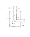
- the dimensions of the rod 12 are determined according to the mold 14 to be used. When the rod 12 is cylindrical, the diameter is, for example, 8 to 12 mm, and the length is, for example, 100 to 200 mm (FIG. 2). reference).
- the rod 12 is plastically deformed by repeatedly subjecting the rod 12 to shear deformation.
- the repeated shear deformation process is performed on the upper part of the mold 14 using, for example, a rectangular parallelepiped mold 14 in which the through hole 13 having a bending angle ⁇ of 90 degrees is formed.
- ECAP Equal-Channel Angular Pressing
- the rod 12 is pushed from the one side opening 15 of the through hole 13 provided and discharged from the other side opening 16 of the through hole 13 provided on the side of the mold 14. This is done by repeating the processing.
- an inorganic lubricant for example, molybdenum disulfide
- the rod 12 When the rod 12 is inserted from the one side opening 15 of the through-hole 13 shown in FIG. 2 and forcedly pushed out from the other side opening 16, the rod 12 passes through the bent portion (the corner where the arc angle becomes ⁇ ). In doing so, shear strain is introduced.
- the reduction rate of the cross-sectional area of the rod 12 before and after the ECAP method is set to more than 0% and 20% or less, that is, the inner diameter of the other side opening 16 is smaller than the inner diameter of the one side opening 15. (For example, the opening cross-sectional area reduction rate is more than 0% and less than 20%.) Therefore, the rod 12 after shear deformation is reduced in diameter, and the rod 12 after shear deformation is opened again on one side.
- the degree of processing applied to the rod 12 by processing can be made constant, and the degree of processing applied to the rod 12 can be easily adjusted by the number of times of shear deformation processing.
- ⁇ M (M / 3 1/2 ) ⁇ (P + Q)
- P 2cot ⁇ ( ⁇ / 2) + ( ⁇ / 2) ⁇
- Q ⁇ cosec ⁇ ( ⁇ / 2) + ( ⁇ / 2) ⁇ .
- the cumulative equivalent strain ⁇ M of the rod 12 that has passed through the through hole 13 M times can be calculated as (M / 3 1/2 ). Therefore, by determining the number of times M that the rod 12 passes through the through-hole 13, with the cumulative equivalent strain epsilon M of the rod 12 can be quantitatively assessed readily, accurately the cumulative equivalent strain epsilon M of the rod 12 Can be adjusted.
- the degree of processing W is expressed by the following equation using the cross-sectional area ratio before and after processing.
- W ln (A 0 / A 1 )
- a 0 indicates a cross-sectional area before processing
- a 1 indicates a cross-sectional area after processing. Since the degree of work is a scale that quantitatively shows the amount of plastic strain accompanying plastic deformation, between the degree of work W and the cumulative equivalent strain ⁇ M , W ⁇ ⁇ M The relationship is established. For this reason, in order to set the processing degree to 1.5 or more, the number M of times the rod 12 passes through the through hole 13 is 2 or more.
- the strain is accumulated in the rod 12.
- the crystal structure constituting the rod 12 becomes energetically unstable as strain energy increases, so recrystallization using strain energy as a drive source.
- the crystal structure becomes finer and attempts to return to an energy stable crystal structure.
- strain energy at a level that enables recrystallization at room temperature is injected into the rod 12.
- the original specimen 11 has a crystal structure with an average crystal grain size of 50 ⁇ m or less by recrystallization.
- the processing degree of the rod 12 is 0.5, the average crystal grain size of the original specimen 11 is 50 ⁇ m or less, and if the processing degree of the rod 12 is 2, the average crystal grain diameter of the original specimen 11 is Is 10 ⁇ m or less, and the processing degree of the rod 12 is 4, the average crystal grain size of the original specimen 11 is 2 ⁇ m or less, and the processing degree of the rod 12 is 6, the average crystal grain diameter of the original specimen 11 is 1 ⁇ m or less.
- the average crystal grain size of the original specimen 11 is 50 ⁇ m or less, and the processing degree of the rod 12 is 1. Then, if the average crystal grain size of the original specimen 11 is 10 ⁇ m or less, the degree of processing of the rod 12 is 3, the average crystal grain diameter of the original specimen 11 is 2 ⁇ m or less, and the degree of processing of the rod 12 is 5, the original test It has been confirmed that the average crystal grain size of the body 11 is 1 ⁇ m or less.
- the average crystal grain size of the original specimen 11 is 50 ⁇ m or less, and if the degree of processing of the rod 12 is 3, the average crystal of the original specimen 11 is If the particle size is 10 ⁇ m or less and the degree of processing of the rod 12 is 6, the average crystal particle size of the original specimen 11 is 2 ⁇ m or less, and if the degree of processing of the rod 12 is 10, the average crystal particle diameter of the original specimen 11 is 1 ⁇ m.
- the processing degree of the rod 12 is 1, the average crystal grain size of the original specimen 11 is 50 ⁇ m or less, and the processing degree of the rod 12 Is 2, the average crystal grain size of the original test specimen 11 is 10 ⁇ m or less, and the processing degree of the rod 12 is 5. If the average crystal grain diameter of the original test specimen 11 is 2 ⁇ m or less and the processing degree of the rod 12 is 8, The average crystal grain size of the original test body 11 has been confirmed to be 1 ⁇ m or less.
- the second step is a primary processing step of cutting out the test piece base material from which the thin plate test piece 10 is based from the original test body 11, and a predetermined thickness (for example, 0. 2 to 0.5 mm), and a thin plate test piece 10 having a predetermined size (for example, 20 to 30 mm in length and 2 to 2 mm in width). 3 mm and a thickness of 0.2 to 0.3 mm).
- the recrystallization temperature of the thin plate test piece 10 is determined by the conductive material forming the thin plate test piece 10.
- a plurality of plate bodies are made of conductive materials that can be applied to cable strands, the plate bodies are roll-rolled at room temperature, and the crystal grains constituting the crystal structure of the plate bodies before and after rolling. It was investigated whether a change of 20% or more was observed in the particle size. As a result, it has been found that no change of 20% or more occurs in the grain size of the crystal structure of the plate-like body before and after rolling when the degree of work is 0.3 or less regardless of the type of conductive material.
- the threshold for determining whether or not there is a change in the grain size of the crystal grains was set to a change rate of 20% because the outer edge and the center of the plate-like body were in the horizontal direction of the roll (along the rolling direction of the plate-like body).
- Coefficient of variation indicating the variation in grain size after processing of the part Is within 10%. For this reason, while producing the thin plate test piece 10 from the original test body 11, the processing degree added to the thin plate test piece 11 shall be 0 or more and 0.3 or less.
- the machining degree in the primary machining process and the tertiary machining process is a negligible value with respect to the machining degree in the secondary machining process.
- the degree of processing applied to the thin plate test piece 11 it is possible to prevent the introduction of strain energy at a level capable of causing recrystallization in the thin plate test piece 11 at room temperature. Does not occur. For this reason, it is possible to produce the thin plate test piece 10 from the original test body 11 while maintaining the state of the crystal structure formed in the original test body 11, and the crystal structure of the thin plate test piece 10 is the same as that of the original test body 11. It becomes the same as the crystal structure.
- the third step one side of the thin plate test piece 10 in the longitudinal direction is attached to the holder, and the holder to which the thin plate test piece 10 is attached is fixed to the voice coil portion of the acoustic speaker.
- the test piece 10 is in a cantilevered support state with the other end in the longitudinal direction being a free end.
- the voice coil is vibrated to adjust the frequency so that the thin plate test piece 10 is in a primary resonance state, and the maximum amplitude of the other end (free end) in the longitudinal direction of the thin plate test piece 10 becomes a predetermined value. Adjust the vibration force of the voice coil as follows. In this resonance state, bending stress generated in the thin plate test piece 10 causes a repeated stress of tension and compression to be applied to the position of the holder base of the thin plate test piece 10, and the fatigue test of the thin plate test piece 10 is performed.
- the repetitive stress is proportional to the maximum amplitude of the free end of the thin plate test piece 10, and the proportionality coefficient is the Young's modulus of the thin plate test piece 10, the secondary moment of the cross section of the thin plate test piece 10, the cross section coefficient of the thin plate test piece 10, And the length from the holder root of the thin plate test piece 10 to the free end can be theoretically calculated.
- the occurrence of cracks is monitored by imaging both surfaces on one side of the thin plate test piece 10 with a CCD camera, and the number of repetitions when the occurrence of cracks is detected is determined. End the test.
- the crystal structure formed in the original test specimen 11 can be maintained during the production of the thin plate test piece 10, and the crystal structure of the thin plate test piece 10 is the same as the crystal structure of the original test specimen 11. Can do.
- the fatigue characteristics obtained from the fatigue test using the thin plate test piece 10 become fatigue characteristics reflecting the crystal structure formed in the original specimen 11. Therefore, original test bodies 11 with different degrees of processing applied to the rods 12 are prepared, thin plate test pieces 10 are prepared from the respective original test bodies 11, and a fatigue test is performed. The fatigue characteristics (relationship between the stress amplitude and the number of fractures) for each crystal structure formed in the body 11 can be obtained.
- the small-diameter cable (element Fatigue characteristics of the wire), for example, the number of breaks of the wire when the stress amplitude is assumed, and the stress amplitude when the number of breaks of the wire is assumed can be predicted.
- the degree of processing applied to the rod 12 can be adjusted accurately and easily by adjusting the number of repetitions of the ECAP method.
- the average crystal grain size of the crystal structure constituting the original specimen 11 can be reliably adjusted, and the average crystal grain size of the crystal structure constituting the thin plate test piece 10 can be controlled.
- the rod 12 when repeating the ECAP method, the rod 12 is rotated around the central axis along the processing direction, and the shear deformation processing is repeated while shifting the circumferential angular position of the shear processing portion in the rod 12. Shear deformation can be uniformly generated over the entire test body 11, and the crystal structure of the original test body 11 can be homogenized. Thereby, the crystal structure of the thin plate test piece 10 can be homogenized, and variations in fatigue characteristics obtained when a fatigue test using the thin plate test piece 10 is performed can be suppressed.
- the rotation of the rod 12 may be performed every time of processing, or may be performed every time a plurality of times of processing.
- Example 1 Four rods with a diameter of 10 mm and a length of 100 mm are taken out from an ingot of aluminum-0.3 mass% scandium-0.3 mass% zirconium-based alloy, the inner diameter of one side opening is 10 mm, the inner diameter of the other side opening Is 9.8 mm, a die having a through hole bent at 90 ° in the middle is attached to a press, and each rod is pushed in from the one side opening formed in the die at a pushing speed of about 200 mm / min.
- the shear deformation process by the ECAP method of pushing in and discharging from the other side opening of the mold was repeated four times at room temperature, and four original specimens with a working degree of 3.8 were produced.
- a test piece base material having a length of 100 mm, a width of 5 mm, and a thickness of 0.36 mm is cut out from each original specimen, and a thin piece having a thickness of 0.32 mm is produced by rolling, and the thin piece is cut and polished.
- the holder to which the thin plate test piece is attached is fixed to the voice coil portion of the acoustic speaker, and the other end of the thin plate test piece in the longitudinal direction is fixed.
- Cantilever support with a free end.
- the frequency is set so that the thin plate test piece is in the primary resonance state, and the vibration force of the voice coil is set so that the repeated stress of tension and compression generated at the position of the holder base of the thin plate test piece becomes a predetermined value.
- the thin plate specimen was resonated and a fatigue test was performed.
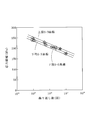
- FIG. 3 shows the relationship (SN curve) between the stress amplitude obtained from the fatigue test and the number of fractures (number of repetitions).
- the four original specimens are distinguished by the marks ⁇ , ⁇ , ⁇ , and ⁇ , and the same mark as the original specimen is used for the thin plate test piece made from the same original specimen. .
- Comparative Example 1 Four rods having a diameter of 10 mm and a length of 100 mm were taken out from the aluminum-0.3 mass% scandium-0.3 mass% zirconium alloy ingot used in Experimental Example 1, and rolled with a rolling roll at a reduction rate of 94%. And four original specimens with a processing degree of 2.8 were produced. Next, a test piece base material having a length of 100 mm, a width of 5 mm, and a thickness of 0.36 mm is cut out from each original specimen, and a thin piece having a thickness of 0.32 mm is produced by rolling, and the thin piece is cut and polished.
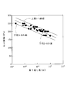
- FIG. 4 shows the relationship (SN curve) between the stress amplitude and the number of breaks obtained from the fatigue test.
- the four original specimens are distinguished by the marks ⁇ , ⁇ , ⁇ , and ⁇ , and the same marks as the original specimen are used for the thin plate specimens made from the same original specimen. .
- FIG. 3 and 4 show the average SN curve obtained based on the fatigue test results of all thin plate specimens, the range of variation of the fatigue test results with respect to the average SN curve, and the lower limit SN. Each curve is shown.
- the upper and lower limit SN curve intervals in FIG. 3 (the difference between the upper limit value and lower limit value of the stress amplitude when the number of repetitions is specified, or the upper limit value and lower limit value of the number of repetition times when the stress amplitude value is specified). The difference is smaller than the interval between the upper and lower limit SN curves in FIG. Therefore, according to the fatigue test method of the conductive material of the present invention, it is possible to produce a fatigue test piece in which the average crystal grain size is adjusted and the crystal structure is homogenized. Was confirmed.
- Example 2 A specimen base material having a length of 100 mm, a width of 5 mm, and a thickness of 0.36 mm was cut out from an aluminum-0.3 mass% scandium-0.3 mass% zirconium-based alloy ingot, and the thickness was reduced to 0. A 32 mm thin piece was produced, and the thin piece was cut and polished to produce a plurality of thin plate test pieces having a length of 30 mm, a width of 3 mm, and a thickness of 0.3 mm. The degree of processing added when obtaining the flakes from the original specimen was 0.12, and the average crystal grain size of the crystal structure was 550 ⁇ m.
- the fatigue test similar to Experimental example 1 was done using the obtained thin-plate test piece.
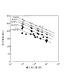
- FIG. 5 shows the relationship (SN curve) between the stress amplitude and the number of fractures obtained from the fatigue test using ⁇ .
- the rod When the ECAP method is repeated twice, the rod is rotated 180 degrees around the central axis when the rod is pushed again into the one side opening of the mold, and when the ECAP method is repeated four times, the rod is When the rod is rotated 90 degrees around the central axis when it is repeatedly pushed into the one side opening, and the ECAP method is repeated six times, the rod is moved around the central axis when the rod is repeatedly pushed into the one side opening of the mold. In the case where the ECAP method is repeated eight times, the rod is rotated 45 degrees around the central axis when the rod is repeatedly pushed into one side opening of the mold.
- a test piece base material having a length of 100 mm, a width of 5 mm, and a thickness of 0.36 mm is cut out from each original specimen, and a thin piece having a thickness of 0.32 mm is produced by rolling, and the thin piece is cut and polished.
- a plurality of thin plate test pieces having a length of 30 mm, a width of 3 mm, and a thickness of 0.3 mm were produced by processing.
- the degree of processing added when obtaining the flakes from the original specimen is 0.12.
- the fatigue test results for the thin plate specimen (ECAP2) obtained from the original specimen prepared by repeating the ECAP method twice are obtained from the original specimen prepared by repeating the ECAP method four times using ⁇ .
- Fatigue test results for thin plate specimens are used for ⁇
- fatigue test results for thin specimens ECAP6 obtained from an original specimen prepared by repeating the ECAP method 6 times are used for ECAP.
- the average crystal grain size of the crystal structure of the original specimen obtained from the original specimen produced by repeating the ECAP method 2, 4, 6, and 8 times is 8 ⁇ m, 1.2 ⁇ m, 0.6 ⁇ m, and 0
- the average crystal grain size of the crystal structure of the thin plate test piece prepared from the original specimen was the same as the average crystal grain diameter of the crystal structure of the original specimen.
- the fatigue test similar to Experimental example 1 was done using the thin-plate test piece obtained from each original test body.
- FIG. 5 shows the relationship between the stress amplitude obtained from the fatigue test and the number of fractures (SN curve).
- a database is created in advance by calculating the relationship between the degree of work and fatigue characteristics, the degree of work applied when manufacturing the strand is calculated, and the degree of work that is the same as or close to that degree is produced.
- the life of the strand under the assumed use condition can be predicted.
- the present invention has been described above with reference to the embodiments. However, the present invention is not limited to the configurations described in the above-described embodiments, and is within the scope of the matters described in the claims. Other possible embodiments and modifications are also included. Further, the present invention includes a combination of components included in the present embodiment and other embodiments and modifications. For example, although the ECAP method (also referred to as ECAE (Equal Channel Angular Extraction) method) is adopted as the shear deformation processing method, an HPT (High Pressure Torsion) method can also be used.
- ECAP method also referred to as ECAE (Equal Channel Angular Extraction) method
- HPT High Pressure Torsion
- the thin cable (wire) under the assumed use condition is applied. Fatigue properties can be predicted. Moreover, when the plastic deformation applied to the workpiece is repeatedly applied by shear deformation, the degree of processing applied to the workpiece can be easily adjusted.
Landscapes
- Physics & Mathematics (AREA)
- Health & Medical Sciences (AREA)
- Life Sciences & Earth Sciences (AREA)
- Chemical & Material Sciences (AREA)
- Analytical Chemistry (AREA)
- Biochemistry (AREA)
- General Health & Medical Sciences (AREA)
- General Physics & Mathematics (AREA)
- Immunology (AREA)
- Pathology (AREA)
- Investigating Strength Of Materials By Application Of Mechanical Stress (AREA)
Applications Claiming Priority (2)
| Application Number | Priority Date | Filing Date | Title |
|---|---|---|---|
| JP2012-132151 | 2012-06-11 | ||
| JP2012132151A JP2015158365A (ja) | 2012-06-11 | 2012-06-11 | 導電材料の疲労試験方法 |
Publications (1)
| Publication Number | Publication Date |
|---|---|
| WO2013187330A1 true WO2013187330A1 (fr) | 2013-12-19 |
Family
ID=49758153
Family Applications (1)
| Application Number | Title | Priority Date | Filing Date |
|---|---|---|---|
| PCT/JP2013/065859 Ceased WO2013187330A1 (fr) | 2012-06-11 | 2013-06-07 | Procédé d'essai de fatigue pour matière conductrice |
Country Status (2)
| Country | Link |
|---|---|
| JP (1) | JP2015158365A (fr) |
| WO (1) | WO2013187330A1 (fr) |
Families Citing this family (1)
| Publication number | Priority date | Publication date | Assignee | Title |
|---|---|---|---|---|
| CN112158359B (zh) * | 2020-10-12 | 2022-01-04 | 中国地质大学(北京) | 一种检测机翼疲劳断裂的方法 |
Citations (5)
| Publication number | Priority date | Publication date | Assignee | Title |
|---|---|---|---|---|
| JPH10183264A (ja) * | 1996-12-19 | 1998-07-14 | Matsushita Electric Ind Co Ltd | ガラスエポキシ基板からの銅の回収方法 |
| JP2002363641A (ja) * | 2001-06-08 | 2002-12-18 | Hyuku Shin Don | Ecap法を用いた炭素鋼の球状化方法 |
| JP2004143560A (ja) * | 2002-10-28 | 2004-05-20 | Matsushita Electric Works Ltd | 熱電変換素子の製造方法 |
| JP2005329459A (ja) * | 2004-05-20 | 2005-12-02 | Ueda Seni Kagaku Shinkokai | 鋳造用結晶粒微細化剤及びその製造方法 |
| JP2009208099A (ja) * | 2008-03-03 | 2009-09-17 | Doshisha | 高靭性軽合金材料及びその製造方法 |
-
2012
- 2012-06-11 JP JP2012132151A patent/JP2015158365A/ja active Pending
-
2013
- 2013-06-07 WO PCT/JP2013/065859 patent/WO2013187330A1/fr not_active Ceased
Patent Citations (5)
| Publication number | Priority date | Publication date | Assignee | Title |
|---|---|---|---|---|
| JPH10183264A (ja) * | 1996-12-19 | 1998-07-14 | Matsushita Electric Ind Co Ltd | ガラスエポキシ基板からの銅の回収方法 |
| JP2002363641A (ja) * | 2001-06-08 | 2002-12-18 | Hyuku Shin Don | Ecap法を用いた炭素鋼の球状化方法 |
| JP2004143560A (ja) * | 2002-10-28 | 2004-05-20 | Matsushita Electric Works Ltd | 熱電変換素子の製造方法 |
| JP2005329459A (ja) * | 2004-05-20 | 2005-12-02 | Ueda Seni Kagaku Shinkokai | 鋳造用結晶粒微細化剤及びその製造方法 |
| JP2009208099A (ja) * | 2008-03-03 | 2009-09-17 | Doshisha | 高靭性軽合金材料及びその製造方法 |
Non-Patent Citations (1)
| Title |
|---|
| MASAYUKI TSUSHIDA ET AL.: "Development of Fatigue Testing Machine for Thin Sheet Specimen and Fatigue Test for Magnesium Single Crystal", JOURNAL OF THE SOCIETY OF MATERIALS SCIENCE, vol. 58, no. 8, 15 August 2009 (2009-08-15), JAPAN, pages 703 - 708 * |
Also Published As
| Publication number | Publication date |
|---|---|
| JP2015158365A (ja) | 2015-09-03 |
Similar Documents
| Publication | Publication Date | Title |
|---|---|---|
| Yao et al. | Influence of heat-treatment on the dynamic behavior of 3D laser-deposited Ti–6Al–4V alloy | |
| Foley et al. | Grain refinement vs. crystallographic texture: Mechanical anisotropy in a magnesium alloy | |
| CN104769140B (zh) | 铜合金及其制造方法 | |
| JP2016180186A (ja) | 微結晶金属導体の製造方法及び微結晶金属導体 | |
| Neishi et al. | Low-temperature superplasticity in a Cu–Zn–Sn alloy processed by severe plastic deformation | |
| Guo et al. | Enhanced microstructure homogeneity and mechanical properties of AZ31 magnesium alloy by repetitive upsetting | |
| Sergey et al. | New combined process “pressing-drawing” and impact on properties of deformable aluminum wire | |
| Zhang et al. | Elastic–plastic finite element analysis and experimental study of short and long fatigue crack growth | |
| CN112872722B (zh) | 梯度纳米结构金属材料及其制备方法 | |
| WO2014196563A1 (fr) | Procédé de production d'un alliage de cuivre et alliage de cuivre | |
| JPWO2018079047A1 (ja) | アルミニウム合金線、アルミニウム合金撚線、被覆電線、及び端子付き電線 | |
| KR20090118404A (ko) | 동적 변형 특성이 개선된 알루미늄 합금의 제조방법 | |
| JPWO2018079048A1 (ja) | アルミニウム合金線、アルミニウム合金撚線、被覆電線、及び端子付き電線 | |
| Faraji et al. | Accumulative torsion back (ATB) processing as a new plastic deformation technique | |
| Wang et al. | Fatigue properties of ultra-fine grain Cu–Cr alloy processed by equal-channel angular pressing | |
| US20060213592A1 (en) | Nanocrystalline titanium alloy, and method and apparatus for manufacturing the same | |
| CN101981211B (zh) | 铍-铜锻造块体 | |
| Figueiredo et al. | Processing magnesium alloys by severe plastic deformation | |
| CN103619506B (zh) | 镁合金材料制造方法及镁合金制棒材 | |
| Yanagimoto et al. | Continuous bending-drawing process to manufacture the ultrafine copper wire with excellent electrical and mechanical properties | |
| Edalati et al. | Processing sheets and wires by continuous high-pressure torsion | |
| Kulczyk et al. | Severe plastic deformation induced in Al, Al-Si, Ag and Cu by hydrostatic extrusion | |
| Kurzydlowski et al. | Effect of severe plastic deformation on the microstructure and mechanical properties of Al and Cu | |
| JP2015158365A (ja) | 導電材料の疲労試験方法 | |
| Lefstad et al. | Up-scaled equal channel angular pressing of AA6060 and subsequent mechanical properties |
Legal Events
| Date | Code | Title | Description |
|---|---|---|---|
| 121 | Ep: the epo has been informed by wipo that ep was designated in this application |
Ref document number: 13804178 Country of ref document: EP Kind code of ref document: A1 |
|
| NENP | Non-entry into the national phase |
Ref country code: DE |
|
| 122 | Ep: pct application non-entry in european phase |
Ref document number: 13804178 Country of ref document: EP Kind code of ref document: A1 |
|
| NENP | Non-entry into the national phase |
Ref country code: JP |