WO2013187418A1 - 繊維強化プラスチック構造体の成形方法と車両用ホイール - Google Patents
繊維強化プラスチック構造体の成形方法と車両用ホイール Download PDFInfo
- Publication number
- WO2013187418A1 WO2013187418A1 PCT/JP2013/066119 JP2013066119W WO2013187418A1 WO 2013187418 A1 WO2013187418 A1 WO 2013187418A1 JP 2013066119 W JP2013066119 W JP 2013066119W WO 2013187418 A1 WO2013187418 A1 WO 2013187418A1
- Authority
- WO
- WIPO (PCT)
- Prior art keywords
- core
- molding
- fiber
- reinforced plastic
- mold
- Prior art date
- Legal status (The legal status is an assumption and is not a legal conclusion. Google has not performed a legal analysis and makes no representation as to the accuracy of the status listed.)
- Ceased
Links
Images




Classifications
-
- B—PERFORMING OPERATIONS; TRANSPORTING
- B29—WORKING OF PLASTICS; WORKING OF SUBSTANCES IN A PLASTIC STATE IN GENERAL
- B29C—SHAPING OR JOINING OF PLASTICS; SHAPING OF MATERIAL IN A PLASTIC STATE, NOT OTHERWISE PROVIDED FOR; AFTER-TREATMENT OF THE SHAPED PRODUCTS, e.g. REPAIRING
- B29C43/00—Compression moulding, i.e. applying external pressure to flow the moulding material; Apparatus therefor
- B29C43/02—Compression moulding, i.e. applying external pressure to flow the moulding material; Apparatus therefor of articles of definite length, i.e. discrete articles
- B29C43/18—Compression moulding, i.e. applying external pressure to flow the moulding material; Apparatus therefor of articles of definite length, i.e. discrete articles incorporating preformed parts or layers, e.g. compression moulding around inserts or for coating articles
-
- B—PERFORMING OPERATIONS; TRANSPORTING
- B29—WORKING OF PLASTICS; WORKING OF SUBSTANCES IN A PLASTIC STATE IN GENERAL
- B29C—SHAPING OR JOINING OF PLASTICS; SHAPING OF MATERIAL IN A PLASTIC STATE, NOT OTHERWISE PROVIDED FOR; AFTER-TREATMENT OF THE SHAPED PRODUCTS, e.g. REPAIRING
- B29C70/00—Shaping composites, i.e. plastics material comprising reinforcements, fillers or preformed parts, e.g. inserts
- B29C70/04—Shaping composites, i.e. plastics material comprising reinforcements, fillers or preformed parts, e.g. inserts comprising reinforcements only, e.g. self-reinforcing plastics
- B29C70/28—Shaping operations therefor
- B29C70/30—Shaping by lay-up, i.e. applying fibres, tape or broadsheet on a mould, former or core; Shaping by spray-up, i.e. spraying of fibres on a mould, former or core
- B29C70/34—Shaping by lay-up, i.e. applying fibres, tape or broadsheet on a mould, former or core; Shaping by spray-up, i.e. spraying of fibres on a mould, former or core and shaping or impregnating by compression, i.e. combined with compressing after the lay-up operation
- B29C70/345—Shaping by lay-up, i.e. applying fibres, tape or broadsheet on a mould, former or core; Shaping by spray-up, i.e. spraying of fibres on a mould, former or core and shaping or impregnating by compression, i.e. combined with compressing after the lay-up operation using matched moulds
-
- B—PERFORMING OPERATIONS; TRANSPORTING
- B29—WORKING OF PLASTICS; WORKING OF SUBSTANCES IN A PLASTIC STATE IN GENERAL
- B29C—SHAPING OR JOINING OF PLASTICS; SHAPING OF MATERIAL IN A PLASTIC STATE, NOT OTHERWISE PROVIDED FOR; AFTER-TREATMENT OF THE SHAPED PRODUCTS, e.g. REPAIRING
- B29C33/00—Moulds or cores; Details thereof or accessories therefor
- B29C33/44—Moulds or cores; Details thereof or accessories therefor with means for, or specially constructed to facilitate, the removal of articles, e.g. of undercut articles
- B29C33/54—Moulds or cores; Details thereof or accessories therefor with means for, or specially constructed to facilitate, the removal of articles, e.g. of undercut articles made of powdered or granular material
-
- B—PERFORMING OPERATIONS; TRANSPORTING
- B29—WORKING OF PLASTICS; WORKING OF SUBSTANCES IN A PLASTIC STATE IN GENERAL
- B29C—SHAPING OR JOINING OF PLASTICS; SHAPING OF MATERIAL IN A PLASTIC STATE, NOT OTHERWISE PROVIDED FOR; AFTER-TREATMENT OF THE SHAPED PRODUCTS, e.g. REPAIRING
- B29C43/00—Compression moulding, i.e. applying external pressure to flow the moulding material; Apparatus therefor
- B29C43/32—Component parts, details or accessories; Auxiliary operations
- B29C43/36—Moulds for making articles of definite length, i.e. discrete articles
-
- B—PERFORMING OPERATIONS; TRANSPORTING
- B29—WORKING OF PLASTICS; WORKING OF SUBSTANCES IN A PLASTIC STATE IN GENERAL
- B29C—SHAPING OR JOINING OF PLASTICS; SHAPING OF MATERIAL IN A PLASTIC STATE, NOT OTHERWISE PROVIDED FOR; AFTER-TREATMENT OF THE SHAPED PRODUCTS, e.g. REPAIRING
- B29C70/00—Shaping composites, i.e. plastics material comprising reinforcements, fillers or preformed parts, e.g. inserts
- B29C70/04—Shaping composites, i.e. plastics material comprising reinforcements, fillers or preformed parts, e.g. inserts comprising reinforcements only, e.g. self-reinforcing plastics
- B29C70/06—Fibrous reinforcements only
-
- B—PERFORMING OPERATIONS; TRANSPORTING
- B60—VEHICLES IN GENERAL
- B60B—VEHICLE WHEELS; CASTORS; AXLES FOR WHEELS OR CASTORS; INCREASING WHEEL ADHESION
- B60B5/00—Wheels, spokes, disc bodies, rims, hubs, wholly or predominantly made of non-metallic material
- B60B5/02—Wheels, spokes, disc bodies, rims, hubs, wholly or predominantly made of non-metallic material made of synthetic material
-
- B—PERFORMING OPERATIONS; TRANSPORTING
- B29—WORKING OF PLASTICS; WORKING OF SUBSTANCES IN A PLASTIC STATE IN GENERAL
- B29C—SHAPING OR JOINING OF PLASTICS; SHAPING OF MATERIAL IN A PLASTIC STATE, NOT OTHERWISE PROVIDED FOR; AFTER-TREATMENT OF THE SHAPED PRODUCTS, e.g. REPAIRING
- B29C43/00—Compression moulding, i.e. applying external pressure to flow the moulding material; Apparatus therefor
- B29C43/32—Component parts, details or accessories; Auxiliary operations
- B29C43/36—Moulds for making articles of definite length, i.e. discrete articles
- B29C2043/3602—Moulds for making articles of definite length, i.e. discrete articles with means for positioning, fastening or clamping the material to be formed or preforms inside the mould
- B29C2043/3605—Moulds for making articles of definite length, i.e. discrete articles with means for positioning, fastening or clamping the material to be formed or preforms inside the mould vacuum
-
- B—PERFORMING OPERATIONS; TRANSPORTING
- B29—WORKING OF PLASTICS; WORKING OF SUBSTANCES IN A PLASTIC STATE IN GENERAL
- B29C—SHAPING OR JOINING OF PLASTICS; SHAPING OF MATERIAL IN A PLASTIC STATE, NOT OTHERWISE PROVIDED FOR; AFTER-TREATMENT OF THE SHAPED PRODUCTS, e.g. REPAIRING
- B29C43/00—Compression moulding, i.e. applying external pressure to flow the moulding material; Apparatus therefor
- B29C43/32—Component parts, details or accessories; Auxiliary operations
- B29C43/36—Moulds for making articles of definite length, i.e. discrete articles
- B29C2043/3665—Moulds for making articles of definite length, i.e. discrete articles cores or inserts, e.g. pins, mandrels, sliders
-
- B—PERFORMING OPERATIONS; TRANSPORTING
- B29—WORKING OF PLASTICS; WORKING OF SUBSTANCES IN A PLASTIC STATE IN GENERAL
- B29C—SHAPING OR JOINING OF PLASTICS; SHAPING OF MATERIAL IN A PLASTIC STATE, NOT OTHERWISE PROVIDED FOR; AFTER-TREATMENT OF THE SHAPED PRODUCTS, e.g. REPAIRING
- B29C43/00—Compression moulding, i.e. applying external pressure to flow the moulding material; Apparatus therefor
- B29C43/32—Component parts, details or accessories; Auxiliary operations
- B29C43/36—Moulds for making articles of definite length, i.e. discrete articles
- B29C2043/3665—Moulds for making articles of definite length, i.e. discrete articles cores or inserts, e.g. pins, mandrels, sliders
- B29C2043/3668—Moulds for making articles of definite length, i.e. discrete articles cores or inserts, e.g. pins, mandrels, sliders destructible or fusible
-
- B—PERFORMING OPERATIONS; TRANSPORTING
- B29—WORKING OF PLASTICS; WORKING OF SUBSTANCES IN A PLASTIC STATE IN GENERAL
- B29K—INDEXING SCHEME ASSOCIATED WITH SUBCLASSES B29B, B29C OR B29D, RELATING TO MOULDING MATERIALS OR TO MATERIALS FOR MOULDS, REINFORCEMENTS, FILLERS OR PREFORMED PARTS, e.g. INSERTS
- B29K2105/00—Condition, form or state of moulded material or of the material to be shaped
- B29K2105/06—Condition, form or state of moulded material or of the material to be shaped containing reinforcements, fillers or inserts
- B29K2105/08—Condition, form or state of moulded material or of the material to be shaped containing reinforcements, fillers or inserts of continuous length, e.g. cords, rovings, mats, fabrics, strands or yarns
- B29K2105/0872—Prepregs
- B29K2105/089—Prepregs fabric
-
- B—PERFORMING OPERATIONS; TRANSPORTING
- B29—WORKING OF PLASTICS; WORKING OF SUBSTANCES IN A PLASTIC STATE IN GENERAL
- B29K—INDEXING SCHEME ASSOCIATED WITH SUBCLASSES B29B, B29C OR B29D, RELATING TO MOULDING MATERIALS OR TO MATERIALS FOR MOULDS, REINFORCEMENTS, FILLERS OR PREFORMED PARTS, e.g. INSERTS
- B29K2105/00—Condition, form or state of moulded material or of the material to be shaped
- B29K2105/06—Condition, form or state of moulded material or of the material to be shaped containing reinforcements, fillers or inserts
- B29K2105/12—Condition, form or state of moulded material or of the material to be shaped containing reinforcements, fillers or inserts of short lengths, e.g. chopped filaments, staple fibres or bristles
-
- B—PERFORMING OPERATIONS; TRANSPORTING
- B29—WORKING OF PLASTICS; WORKING OF SUBSTANCES IN A PLASTIC STATE IN GENERAL
- B29L—INDEXING SCHEME ASSOCIATED WITH SUBCLASS B29C, RELATING TO PARTICULAR ARTICLES
- B29L2022/00—Hollow articles
-
- B—PERFORMING OPERATIONS; TRANSPORTING
- B29—WORKING OF PLASTICS; WORKING OF SUBSTANCES IN A PLASTIC STATE IN GENERAL
- B29L—INDEXING SCHEME ASSOCIATED WITH SUBCLASS B29C, RELATING TO PARTICULAR ARTICLES
- B29L2031/00—Other particular articles
- B29L2031/32—Wheels, pinions, pulleys, castors or rollers, Rims
-
- B—PERFORMING OPERATIONS; TRANSPORTING
- B60—VEHICLES IN GENERAL
- B60B—VEHICLE WHEELS; CASTORS; AXLES FOR WHEELS OR CASTORS; INCREASING WHEEL ADHESION
- B60B2310/00—Manufacturing methods
- B60B2310/20—Shaping
- B60B2310/204—Shaping by moulding, e.g. injection moulding, i.e. casting of plastics material
-
- B—PERFORMING OPERATIONS; TRANSPORTING
- B60—VEHICLES IN GENERAL
- B60B—VEHICLE WHEELS; CASTORS; AXLES FOR WHEELS OR CASTORS; INCREASING WHEEL ADHESION
- B60B2360/00—Materials; Physical forms thereof
- B60B2360/30—Synthetic materials
- B60B2360/34—Reinforced plastics
- B60B2360/341—Reinforced plastics with fibres
- B60B2360/3412—Glass fibres
-
- B—PERFORMING OPERATIONS; TRANSPORTING
- B60—VEHICLES IN GENERAL
- B60B—VEHICLE WHEELS; CASTORS; AXLES FOR WHEELS OR CASTORS; INCREASING WHEEL ADHESION
- B60B2360/00—Materials; Physical forms thereof
- B60B2360/30—Synthetic materials
- B60B2360/34—Reinforced plastics
- B60B2360/341—Reinforced plastics with fibres
- B60B2360/3414—Aramide fibres
-
- B—PERFORMING OPERATIONS; TRANSPORTING
- B60—VEHICLES IN GENERAL
- B60B—VEHICLE WHEELS; CASTORS; AXLES FOR WHEELS OR CASTORS; INCREASING WHEEL ADHESION
- B60B2360/00—Materials; Physical forms thereof
- B60B2360/30—Synthetic materials
- B60B2360/34—Reinforced plastics
- B60B2360/341—Reinforced plastics with fibres
- B60B2360/3416—Carbone fibres
-
- B—PERFORMING OPERATIONS; TRANSPORTING
- B60—VEHICLES IN GENERAL
- B60B—VEHICLE WHEELS; CASTORS; AXLES FOR WHEELS OR CASTORS; INCREASING WHEEL ADHESION
- B60B2360/00—Materials; Physical forms thereof
- B60B2360/30—Synthetic materials
- B60B2360/34—Reinforced plastics
- B60B2360/344—With woven material
-
- B—PERFORMING OPERATIONS; TRANSPORTING
- B60—VEHICLES IN GENERAL
- B60B—VEHICLE WHEELS; CASTORS; AXLES FOR WHEELS OR CASTORS; INCREASING WHEEL ADHESION
- B60B2360/00—Materials; Physical forms thereof
- B60B2360/30—Synthetic materials
- B60B2360/34—Reinforced plastics
- B60B2360/346—Material impregnated with resin before being put into form, i.e. prepregs
-
- Y—GENERAL TAGGING OF NEW TECHNOLOGICAL DEVELOPMENTS; GENERAL TAGGING OF CROSS-SECTIONAL TECHNOLOGIES SPANNING OVER SEVERAL SECTIONS OF THE IPC; TECHNICAL SUBJECTS COVERED BY FORMER USPC CROSS-REFERENCE ART COLLECTIONS [XRACs] AND DIGESTS
- Y10—TECHNICAL SUBJECTS COVERED BY FORMER USPC
- Y10S—TECHNICAL SUBJECTS COVERED BY FORMER USPC CROSS-REFERENCE ART COLLECTIONS [XRACs] AND DIGESTS
- Y10S425/00—Plastic article or earthenware shaping or treating: apparatus
- Y10S425/809—Seal, bottle caps only
Definitions
- the present invention relates to a method for forming a fiber reinforced plastic (FRP: Fiber Reinforced Plastics) structure having a closed cross section using a core, typically by a method for molding a vehicle wheel made of fiber reinforced plastic and the same molding method.
- FRP Fiber Reinforced Plastics
- the present invention relates to an obtained vehicle wheel.
- Fiber-reinforced plastic structures with closed cross-sections are widely used from large structures such as aircraft fuselages and wings to small structures such as bicycle frames, tennis rackets, fishing rods, and golf shafts.
- fiber reinforced plastic structures having an open cross section are widely used in helmets and the like.
- a core for forming a closed cross section a core formed by wrapping powder particles with a packaging film and vacuum-packaging and forming a predetermined shape, a core formed by blow molding, or the like is used. Yes.
- a core in which powder particles packed in a vacuum package are formed into a desired shape for example, a molded body having a hollow portion disclosed in JP-A-2-238912 (Patent Document 1) and its molding
- a core formed by blow molding for example, a multilayer plastic molded body disclosed in Japanese Patent Laid-Open No. 7-1000085 (Patent Document 2) and a method for manufacturing the same are proposed.
- FIG. 8 shows a state in the middle of forming a structure having a hollow portion which is a kind of closed section by the molding die 30. That is, this figure shows a state in which a sheet-like fiber-reinforced thermoplastic resin material (lower FRTP) 34 that has been preheated and is in a molten state is placed on the lower mold 31 of the molding die 30. Since the lower FRTP 34 is in a molten state, the lower FRTP 34 hangs down due to its own weight and sinks into the recess of the lower mold 31.
- FIG. 9 schematically shows the state shown in FIG.
- the core 33 obtained by wrapping the powder particle group 33a with the packaging material 33b and solidified into a predetermined shape by vacuum packing has a structure shown in FIG. 9 and is in a molten state and is hung down by its own weight. Is placed in the recess. On the upper part of the lower FRTP 34 on which the core 33 is placed, a new sheet-like upper FRTP 35 that is heated and melted is placed. In this state, the core 33 is surrounded by the lower FRTP 34 and the upper FRTP 35.
- the upper mold 32 of the molding die 30 is lowered, and the upper FRTP 35 and the lower FRTP 34 are pressurized and solidified integrally with the lower mold 31 to wrap the core 33 inside.
- the upper FRTP 35 and the lower FRTP 34 are formed integrally.
- a small hole is made in the semi-molded product.
- the powder particle group 33a constituting the core 33 is discharged out of the semi-molded product to complete the molded product.
- the packaging material 33b in which the powder particle group 33a is vacuum-packed is made of a material having good peelability with respect to the molded product, the packaging material 33b can also be easily removed from the molded product.
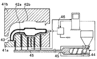
- FIG. 10 shows a state where a core molded by blow molding is set between molding dies 41a and 41b for molding the outer layer.
- the molding dies 41a and 41b are configured to accommodate the core 43.
- the molding dies 41a and 41b are clamped, the molding dies 41a and 41b are aligned with each other.
- a cavity is formed between the surfaces 42a and 42b and the core 43 as a hollow portion for filling the molten resin.
- the molten resin 45 plasticized by the extruder 44 is supplied into the cavity.
- a product having a hollow portion can be molded into a desired shape.
- the core 43 may be deformed. Further, if there is a wide flat portion in the shape of the core 43, the rigidity of the flat portion tends to be insufficient, so that the core 43 is similarly deformed.
- the invention described in Patent Document 2 adopts a configuration that can increase the internal pressure of the core 43.
- a pressurizing unit 46 communicating with the core 43 is provided. By introducing pressurized gas or liquid into the core 43 from the pressurizing unit 46, the internal pressure of the core 43 is increased. Can be increased.
- the upper die 32 is lowered while the core 33 is sandwiched between the lower FRTP 34 and the upper FRTP 35, and the lower FRTP 34 and the upper FRTP 35 are interposed between the upper die 32 and the lower die 31. Is being pressurized.
- the core 33 is placed in the concave portion of the lower FRTP 34 formed by sinking into the concave portion of the lower mold 31, or when the upper FRTP 35 is placed on the core 33, the corner portion in the concave portion of the lower mold 31 A gap is generated between the inner core 33 and the lower FRTP 34 or between the core 33, the lower FRTP 34, and the upper FRTP 35.
- the lower FRTP 34 and the upper FRTP 35 cannot be sufficiently supported from the inside by the core 33, and in particular, the upper mold In the part of the lower FRTP 34 molded along the same direction as the vertical direction in which the 32 moves, that is, in the vertical part, the thickness changes, and further, the outer surface shape of the lower FRTP 34 is changed in the concave part of the lower mold 31. It may not be formed into a shape that conforms to the corner shape, may be wrinkled on the outer surface, or may be formed into a shape that is buckled in the vertical direction. Or the length dimension in a vertical part is shape
- the lower FRTP 34 and the upper FRTP 35 are made of a long fiber reinforced resin material using long fibers, between the core 33 and the lower FRTP 34 and the upper FRTP 35, or between the upper mold 32 and the lower mold 31 and the lower FRTP 34.
- the pressure molding is performed with a gap between the upper FRTP 35 and the upper FRTP 35, the fiber orientation of the long fibers is disturbed to cause bending, resulting in a decrease in strength as a fiber reinforced plastic, a deterioration in the appearance of the molded product, etc. Will be invited.
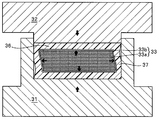
- FIG. 9 shows a state in which an annular prepreg 36 having a core 33 disposed therein is housed in a recess formed in the lower mold 31 and the upper mold 32 is lowered toward the lower mold 31.
- the amount of the powder particle group constituting the core 33 is small, a gap is formed between the prepreg 36 and the core 33, and bending occurs in the vertical portion 37 of the prepreg 36. That is, as shown in FIG. 9, a part of the vertical portion 37 is deformed into a shape curved toward the core 33 side. In addition, when the powder particles constituting the core 33 have low fluidity, the influence of deformation becomes significant. Further, even if a part of the vertical portion 37 is not curved toward the core 33 side, as shown in FIG. 9, the length dimension of the vertical portion 37 is set to a prescribed value unless the lowering amount of the upper mold is regulated. It will be compressed to a length dimension shorter than the length dimension.
- the preform accuracy of the prepreg 36 is improved so that a gap is not formed between the prepreg 36 and the core 33, It is necessary to form the child 33 in a desired shape.
- the amount of powder particles constituting the core 33 is accurately measured and configured, the shape is fixed to a desired shape, and the prepreg 36 is brought into close contact with the core 33, the outer shape of the prepreg 36 is simultaneously changed.
- the powder particle group having fluidity and the uncured prepreg are unstable in shape. It takes a long time for molding.
- the internal pressure of the core 43 can be increased by introducing pressurized gas or liquid into the core 43.
- a pressurized gas or liquid the pressure at an arbitrary point has the physical property of being the same pressure in all directions.
- the leaked gas or liquid becomes a high-speed, high-pressure jet flow, As it is, it will be ejected from the gap between the molding dies 41a and 41b.
- there is a risk of serious damage to the mold and the operator's safety so equipment with sufficient safety measures is required. Become.
- the present invention solves the above-mentioned conventional problems, and at the time of molding a molded product having a closed cross section by a molding die, particularly a molded product having a complicated structure, the prepreg and the core without using gas or liquid. Even when pressure is applied to the core or when a normal molding die is used, a part of the core constituent material is used for molding. It is an object of the present invention to provide a molding method of a fiber reinforced plastic structure that can prevent leakage from a mold, particularly a molding method that can be suitably applied to a vehicle wheel, and the vehicle wheel.
- the present invention uses a core in which a group of particles including a large number of highly rigid particles is accommodated in a bag made of a flexible material.
- a plastic film or a hollow plastic structure formed by blow molding can be used as the bag body.
- a predetermined amount of particles are measured on the bag-shaped plastic film, molded into a predetermined shape, and the bag is evacuated to maintain the predetermined shape as a vacuum pack.
- particles are introduced into the hollow plastic molded body through a hole in a part of the wall surface of the hollow plastic molded body. And it can be set as the core which maintains a predetermined shape by filling the space inside a hollow plastic molding.
- a plurality of particles are filled into a flexible plastic bag to form a plurality of cores. Placing the core in close contact with one side of a prepreg layer composed of one or more prepregs, placing another core in close contact with the other side of the prepreg layer, in the prepreg layer.
- the main constitution is to cure the impregnated resin and to remove the highly rigid particles filled in the core from the bag.
- the method includes curing the resin in a pressurized state of the prepreg in which the core is accommodated in a cavity of a molding die.
- a pressing means that protrudes and protrudes toward the cavity in the mold, pressing a part of the outer peripheral surface of at least one core to increase the internal pressure of the core and deform the core,
- a mold block is molded to press a part of the outer peripheral surface corresponding to each of the symmetrically selected cores. It is preferable to insert and press it toward the cavity along the metal mold.
- the particle group preferably includes particles having different diameters, and the particle group preferably includes highly rigid particles and elastic particles.
- an independent metal member (not shown) may be further disposed in the molding die, and may be formed integrally with the prepreg. After the prepreg is integrally molded, the particle group can be discharged to the outside of the molded product through the metal member.
- a plurality of cores are filled with a large number of particles, mainly high-rigidity particles, in a flexible material.
- Forming the core in close contact with one side of the reinforcing fiber base, placing another core in close contact with the other side of the reinforcing fiber base, and the reinforcing fiber base The main configuration includes impregnating the material with a resin to cure the resin, and removing the highly rigid particles filled in the core from the bag.
- the pressing means that protrudes and protrudes toward the cavity in the mold presses a part of the outer peripheral surface of at least one core to increase the internal pressure of the core and deform the core, and It is preferable to include improving adhesion between the prepreg, the mold, and all the cores arranged in the cavities in the mold by pressing deformation of the core.
- a metal member as described above may be further disposed in the molding die cavity, and the reinforcing fiber base and the metal member may be integrally formed.
- a third aspect of the present invention resides in a vehicle wheel manufactured by the above-described molding method of a fiber-reinforced plastic structure having a plurality of cavities.
- a group of particles having high fluidity including a large number of particles having high rigidity, are respectively accommodated in a plurality of bags formed into a desired three-dimensional shape by blow molding, vacuum molding, injection molding, or the like. These are used as molding cores.
- the plurality of molding cores are not simply arranged next to each other in accordance with the shape of the cavity of the fiber-reinforced plastic structure, but are prepregs or reinforcing fiber substrates (hereinafter simply referred to as “fiber cores”).
- the fiber reinforced plastic molded product can be placed between multiple cavities even if it is a complicated cavity arrangement of the finished product with the molding core removed.
- a fiber reinforced plastic structure having a complicated structure can be obtained by interposing a fiber reinforced plastic molded article integrally between a plurality of cavities having a complicated arrangement and shape.
- the fiber reinforced plastic structure can be provided with the required strength and form stability.
- the core is pressed by pressing a part of the outer surface of at least one core through the reinforcing fiber material or without these reinforcing fiber materials. Sliding is forcibly generated between the particles of the constituting particle group, and the outer surface of the core is deformed so as to spread.
- the reinforcing fiber material can be moved in a direction to fill the gap by deformation of the core, Generation
- gap can be eliminated.
- the void formed between the reinforcing fiber material and the core due to the deformation of the core is crushed by the high internal pressure by the core, or the air forming the void is released from the molding die through the reinforcing fiber material into the atmosphere. Will be.
- the passage formed when air passes through the reinforcing fiber material is naturally occluded by the molten resin after the air is exhausted.
- the core has a structure in which a large number of particle groups including highly rigid particles are accommodated inside. For this reason, even if a part of the outer surface of the core is pressed to be deformed so that the surface area of the outer periphery of the core is increased, the internal pressure in the core is usually liquid or liquid unless special measures are taken. A uniform pressure state is not obtained in all parts as in the case of using gas. That is, even if a pressure is applied to a part of the particle group, a pressure smaller than the pressure at the part where the pressure is applied at another part is generated. When the pressure applied at this time exceeds a certain value, slip occurs between the particles constituting the particle group.
- the transmission of pressure in the core and the fluidity of the particle group are affected by the shape of the particles constituting the particle group, the roughness of the particle surface, and the particle diameter.
- the core is filled with particles at a high density, the fluidity of the particle group is hindered, and the pressure transferability is impaired. Therefore, by taking into account the particle size distribution and particle surface roughness distribution in the core, or using a combination of particles with different particle sizes to break down the high-density packing state, This improves the fluidity and pressure transmission of the particle group.
- the fluidity and pressure transferability of the particle group in the core can also be improved by using a particle group composed of highly rigid particles and elastic particles as the particle group.
- the core is deformed so that the outer peripheral surface area of the core is widened by the sliding of the particles constituting the particle group even at a site away from the pressed site.
- the reinforcing fiber material can be pressed against the molding surface of the molding die, for example, the core supporting the vertical portion in the vertical direction parallel to the pressing direction of the die.
- the pressure can be increased between the site and the reinforcing fiber material. Further, it is possible to prevent the vertical portion as described above from being bent and deformed during pressurization by the upper die and the lower die.
- the core is pressed.
- the pressure between the outer surface of the fiber and the inner surface of the reinforcing fiber material can be increased.
- the fiber-reinforced plastic structure having the outer surface filled with the reinforcing fiber material at the corners can be molded.
- each particle constituting the particle group moves by sliding in the front, rear, left, and right directions, but the bag body containing the particle group is made of a stretchable material. Yes. Therefore, deformation of the outer shape of the core accompanying movement of each particle group can be allowed by the stretchable bag.
- the gap of the molding die constitutes the particle group. If it is smaller than the diameter of the particles to be produced, it will not leak from the molding die unless the particles are crushed. However, in the unlikely event that the particles are crushed and leaked out of the molding die, the resulting cavity of the fiber-reinforced plastic structure will be deformed, and the shape of the fiber-reinforced plastic structure will be May also be affected. Therefore, in the present invention, a highly rigid material is used for the particles.
- the mold block is a metal block that forms part of the molding mold and can be moved into and out of the molding surface of the molding die.
- the mold block can be configured by a plunger or external operation.
- a metal block with a mechanism that can slide part of the inner surface is used.
- the core is used to define the arrangement of the reinforcing fiber material and the plurality of cores as described above. By combining these cores, a closed cross-section with high accuracy and a required strength is secured. A molding method capable of efficiently molding a fiber-reinforced plastic structure having a complicated structure is realized. As described above, since a plurality of cores are used in the present invention, the pressing means is applied to one part or a plurality of parts of the molding die corresponding to the pressing part of each core that requires pressing. Install.
- a recess is formed in the reinforcing fiber material. It is preferable that a hole is formed in the concave portion formed in the pressed portion, and the particle group constituting the core is discharged from the semi-molded product.
- the pressing place has a substantially planar shape, when the entire plane is pressed through the reinforcing fiber material, the surface sinks as a whole, so that substantially no recess is formed.
- the discharge hole for discharging the particle group constituting the core can be arbitrarily provided in addition to the depressed portion, the flat portion, or the pressed portion.
- a hole having a size corresponding to a pressing portion such as a mold block is previously opened in the reinforcing fiber material, and the hole is passed through the hole. Pressurize the core directly.
- the bag body can be broken from the hole position formed in the molded product, and the particles can be discharged.
- FIG. 1 It is an initial state figure at the time of shaping
- FIG. It is sectional drawing which shows typically the state at the time of the pressure molding of FIG. It is a system diagram which shows the state which set the core between the metal mold
- FIG. 1 It is an initial state figure at the time of shaping
- FIG. It is sectional drawing which shows typically the state at the time of the pressure molding of FIG. It is a system diagram which shows the state which set the core between the metal mold
- the method for molding the fiber-reinforced plastic structure according to the present invention includes a part of the core during pressure molding by the molding die, including the configuration of the molding die and core described below. If it is the structure which can expand a surface area, various deformation
- a method for molding a vehicle wheel made of fiber reinforced plastic which is a typical molded product of a fiber reinforced plastic structure
- the method for molding the fiber-reinforced plastic structure of the present invention is not limited to the method for molding a vehicle wheel, and other large-scale moldings such as a vehicle body such as an automobile or a train, or a fuselage or wing of an airplane. It can also be applied to products.
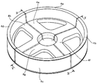
- FIG. 1 and 2 show a vehicle wheel 10 made of a fiber-reinforced plastic molded product.
- the vehicle wheel 10 has a plurality of cavities formed therein for weight reduction.
- a plurality of cores 4 are used.
- the entire core 4 of the wheel is divided into four along the dividing lines IV-IV and VV shown in FIG. 3, and the four cores 4a used for the rim portion 11 are also divided.
- To 4d and the four cores 4e to 4h used for the disk unit 12 are separated to form eight divided cores 4a to 4h.
- the split cores 4a to 4h are made by filling a bag-shaped molded product (bag body) manufactured by blow molding with high-rigidity particles alone or mixed particles of high-rigidity particles and elastic particles.
- the split cores 4a to 4h thus produced are not only arranged along the shape of the cavity formed in the vehicle wheel 10, but are arranged via the prepreg. Specifically, as shown in FIG.
- the split core 4 a of the rim portion 11 is disposed in close contact with one surface of the prepreg 3 arranged in a predetermined region of the lower mold 1, and the other prepreg 3
- the split cores 4e of the disk portion 12 adjacent to the surface are disposed in close contact with each other, and the entire surfaces of the split cores 4a and 4e are covered with the prepreg 3.
- the split cores 4b to 4d remaining in the rim portion 11 and the split cores 4f to 4h remaining in the disk portion 12 are covered with the prepreg 3 in the same manner as the split cores 4a and 4e.
- the prepregs 3 covering the respective split cores 4a to 4h are arranged in close contact with each other in the corresponding cavities of the lower mold 1 and the side mold 2b shown in FIG.
- the upper mold 2a and the mold block 5a are lowered together.
- the lower surface of the upper mold 2a and the lower surface projecting end surface of the mold block 5a are in contact with the prepreg 3 arranged in advance, respectively, to the partial surface of the prepreg 3 Pressurization is started and the upper mold 2a reaches a predetermined lower limit position, while the mold block 5a continues to be pressurized.
- the lower limit position of the lowering of the upper mold 2a at this time is determined by the height of the upper surface position of the side mold 2b, but the mold block 5a presses the surface of the prepreg 3 without colliding with the mold.
- the resin impregnated in the prepreg layer is cured to form a fiber reinforced plastic structure having a desired shape.
- the upper die 2a in the present embodiment is for the purpose of regulating the position of the upper end flat surface portion, which is a part of the outer surface of the rim portion 11 of the vehicle wheel 10.
- 5a is used exclusively for pressurizing a part of the upper surface of the disk portion 12 of the vehicle wheel 10 by the protruding portion 5a '.
- the pressure by pressurization of the mold block 5a is transmitted by the flow of the particle group filled in the core, and the upper end flat part which is a part of the outer surface of the rim part 11 of the vehicle wheel 10 pushes the upper mold 2a.
- the upper mold 2a is fixed so as not to move by this force.
- the upper mold 2a, the mold block 5a, the side mold 2b, and the lower mold 1 are the entire prepreg 3 that independently encloses the eight divided cores 4a to 4h arranged in the cavity formed by them. Pressurize.
- the prepreg 3 can be configured as a sheet-like material in which reinforcing fibers such as carbon fiber, glass fiber, aramid fiber, and silicon carbide fiber are impregnated with an uncured thermosetting resin.
- the type of reinforcing fiber is selected according to the performance of the target fiber-reinforced plastic structure.
- the plurality of split cores 4a to 4h form adjacent cavities via the prepreg 3 covering each of them.
- the plurality of split cores 4a to 4h are individually covered. It is also possible to add a plurality of layers of prepregs 3 between the prepregs 3.
- the eight divided cores 4a to 4h individually covered with the prepreg 3 are set in the lower mold 1.
- the eight divided cores 4a to 4h are individually covered with the prepreg 3. It is also possible to set the lower mold 1 after stacking prepregs so as to cover the whole after combining them. In the embodiment shown in FIGS.
- the dividing direction of the core of the disk portion 12 and the dividing direction of the rim portion 11 are made to coincide with each other, but it is not always necessary to make the both dividing directions coincide.
- the relative arrangement in the dividing direction can be selected so as to optimize the type of fiber reinforced plastic structure to be obtained, the distribution of stress during use, and the distribution of mass.
- the prepreg sandwiched between each of the split cores 4a to 4h of the rim portion 11 and the disk portion 12, and each of the split cores 4a to 4d of the rim portion 11 and each of the disk portion 12 is provided.
- thermosetting resin is used.
- a prepreg impregnated with a thermoplastic resin instead of a thermosetting resin
- a preform formed by preheating the prepreg 3 is molded.
- An FRP molded product having a desired shape can be produced by pressure-cooling with a mold for use.
- a plurality of cores are individually covered with a reinforcing fiber substrate such as a reinforced fiber woven fabric, placed in the molding die, the molding die is closed, and then the molding die is molded. It can also be applied to resin transfer molding in which a thermosetting resin is pressure-injected and filled into a cavity between the surface and the reinforcing fiber base covering each core, and is cured by a heating mold. .
- Epoxy resin, urea resin, vinyl ester resin, unsaturated polyester, polyurethane, phenol resin, etc. can be used as the thermosetting resin impregnated into the fiber, and polypropylene, polyethylene, polystyrene, vinyl chloride can be used as the thermoplastic resin. Polyamide resin or the like can be used.
- the core 4 is configured by filling a bag group 6 such as a blow molded product, a vacuum molded product, or an injection molded product shaped into a desired outer shape with a particle group having high rigidity.
- a bag group 6 such as a blow molded product, a vacuum molded product, or an injection molded product shaped into a desired outer shape with a particle group having high rigidity.
- ceramics such as alumina and zirconia, glass, hard heat resistant resin, metal, foundry sand, and the like can be used.
- zirconia or quartz is used as the particles, these materials are suitable materials because of their low thermal conductivity.
- Nylon, polypropylene, polyethylene, acrylic resin, fluororesin film, silicon rubber, etc. can be used as the material of the bag body 6 used to maintain the shape of the core 4, and when the bag body is not removed, Nylon with excellent resin adhesion is suitable.
- the mold block 5a constitutes a part of the upper mold of the molding mold 15, and has a plurality of projecting portions 5a ′ that can be projected and retracted in the cavity of the molding mold 15 on the lower surface of the main body. is doing.
- the protrusion 5 a ′ is formed integrally with the main body, and can protrude and retract into the cavity of the molding die 15 together with the main body. Therefore, a cylinder and a plunger (not shown) are connected to the main body of the mold block 5a.
- the mold block 5a has a configuration that is slidably fitted to the inner peripheral surface of the upper mold 2a.
- the main body of the mold block 5a and the protruding portion 5a ′ may be separated. In that case, it is possible to provide independent operating means such as a cylinder and a plunger on the main body of the mold block 5a and the protrusion 5a ′.
- FIG. 3 a molding material in which eight split cores 4a to 4h divided along a rim part 11 and a disk part 12, and a parting line IV-IV and parting line VV are individually wrapped with a prepreg (
- the forming raw materials 3a to 3h are respectively placed at predetermined positions in the cavity formed by the lower die 1 and the horizontally movable side surface die 2b placed on the lower die 1.
- the upper mold 2a is lowered toward the lower mold 1 and fixed with the side mold 2b interposed therebetween, and the mold is clamped.
- the molding raw materials 3a to 3h are heated from the time when they are placed on the lower mold 1, but can be efficiently heated from the entire circumference by clamping.
- the pressure is not high, and since the pressure is increased by the mold block 5a in the next stage, a mold opening / closing mechanism is sufficient as the mold clamping machine, and a high-pressure press is not required.
- the die block 5 a is pushed into the cavity of the molding die 15, and a part of the outer surface of each of the split cores 4 a to 4 h covered with the prepreg 3 is pressed through the prepreg 3.
- slip occurs between the particles constituting the particle group 6 a in the core 4, the particle group 6 a flows, the core 4 is deformed, and the outer peripheral surface area of the core 4 increases.
- the core 4 can reach the four corners of the inner surface of the prepreg 3 where gaps are particularly likely to occur without gaps, so that the core 4 can be brought into close contact with the inner surface of the prepreg 3, and bending and wrinkling can occur.
- a molded product with high dimensional accuracy without any defects can be obtained.
- the air constituting the gap is It will be crushed by the high internal pressure due to, or it will be discharged from the molding die 15 through the prepreg 3 into the atmosphere.
- the passage formed when air passes through the prepreg 3 is naturally blocked by the molten prepreg 3 after the passage of air.
- the pressure from the core 4 is increased by the expansion of the outer peripheral surface area of the core. Occurs and the prepreg 3 moves to the air gap side. And the air which formed this space
- FIG. The prepreg 3 moves to the space where the air is pushed out, and is formed into a shape along the corner shape of the molding die 15.
- the molded product formed by heating and pressurizing the prepreg 3 can be, for example, a molded product with corners formed at right angles or acute angles, or an undercut shape.
- the thickness of the bag body 6 is shown thick in an exaggerated state in order to explain the bag body 6 in an easy-to-understand manner.
- the bag body 6 can be configured to be around 1 mm.
- the configuration for molding a molded article for a vehicle wheel is described, but the design of the disk shape, the rim width, etc. can be applied as appropriate, and the molded article has other shapes having a closed cross section.
- it is possible to form a more complicated structure such as a combination of a closed cross section and an open cross section.
- the shape close to the closed cross section includes a C-shaped cross section.
- a C-shaped cross section For example, when forming a molded product having a C-shaped cross-sectional shape, an arrangement configuration in which a part of the core is brought into direct contact with the molding surface of the upper mold 2a, the mold block 5a or the lower mold 1 is adopted. can do.
- the molded product which has C-shaped cross-sectional shape can be shape
- the closed cross-section in the present invention includes, for example, a C-shaped cross-sectional shape in addition to a shape such as a square pipe shape.
- the particles constituting the particle group 6a slide in each other and move in the front, rear, left, and right directions, and the particle group 6a is moved to a lower pressure side. Expanding. Since the bag body 6 including the particle group 6a is made of a relatively soft material such as a thermoplastic resin, the bag body 6 does not substantially limit the movement of the particle group 6a, and the outer periphery of the core. It can be stretched to increase the surface area.
- the expansion of the outer surface area of the core 4 occurs at a portion where the pressure between the core 4 and the prepreg 3 is low, so that the thickness of the prepreg 3 is reduced to a predetermined thickness while eliminating the gap. Can be maintained.
- the molded product can be pressure-molded into a shape having a predetermined thickness and a desired outer surface shape.
- FIG. 6 shows a state in which a semi-molded product that has been subjected to pressure molding by the molding die 15 is taken out from the molding die 15. Since the part of the prepreg 3 pressed by the mold block 5a presses the entire upper surface rather than a part of the upper surface of the part where the divided cores 4a to 4h exist, no trace of pressing is recognized in appearance.
- This figure is one of the metal members in the present invention when placed between the four cores 4e to 4h of the disk portion 12 covered with the prepreg and pressurizing and heating with a molding die. An example in which the axle metal hub 7 can also be integrally formed is shown.
- the vehicle wheel which is a molded product having a hollow portion can be completed.
- the bag 6 shaped into a three-dimensional shape such as a blow molded product, a vacuum molded product, or an injection molded product that contains the particle group 6a has a large discharge hole for the particle group 6a. If the structure of the material with good releasability and the bag body 6 are doubled, the bag body 6 in contact with the particle group 6a can be removed from the molded product, but the bag body is thick. When the shape is complicated and it is difficult to take out the bag, it is possible to leave the bag in the molded product and bond the molded product and the bag.
- the molded product has a desired thickness with no desired bending or wrinkle. It can be manufactured as a product having a surface shape. Even when the internal pressure in the core 4 is low when the molding die is closed, the internal pressure in the core 4 can be increased by the pressing force applied from the mold block 5a, for example. As a product, it can be manufactured into a product having a desired thickness and a desired outer surface shape.
- the present invention will be described more specifically based on examples.
- Example 1 The core 4 for forming the internal cavity of the vehicle wheel shown in FIG. 3 is divided into the core of the rim portion 11 and the core of the disk portion 12, and is further divided into dividing lines IV-IV and VV in the same figure.
- a total of eight split cores 4a to 4h having the shapes shown in FIGS. 4 and 5 were created.
- Each of the split cores 4a to 4h accommodates zirconia particles (mixed with a diameter of 1 mm and 3 mm) in a bag 6 made of a nylon blow molded product, and has eight split cores 4a to 4h having the shape shown in FIG. Was made.
- Eight molding raw materials were prepared by covering each of the split cores 4a to 4h with carbon fiber reinforced epoxy resin prepreg 3 (TR3110 391 IMU manufactured by Mitsubishi Rayon Co., Ltd.) laminated in five layers. This was combined with the shape of the inner peripheral surface of the lower mold 1 and assembled at room temperature to form a preform. At this time, since the surface of each forming raw material is wrapped with the prepreg 3, the prepreg 3 is interposed between the adjacent split cores 4a to 4h of the preform.
- carbon fiber reinforced epoxy resin prepreg 3 TR3110 391 IMU manufactured by Mitsubishi Rayon Co., Ltd.
- the upper mold 2a is lowered toward the lower mold 1 and then the mold is clamped.
- the mold block 5a was lowered, and a part of the outer surface of each of the split cores 4a to 4h was pressed at 4 MPa through the prepreg 3 with the protruding portion 5a ′.
- the mold was opened and the semi-molded product was taken out.
- a discharge hole is formed in a portion of the prepreg 3 arranged on the surface of each core on the surface of the semi-molded product, and the particle group 6a is discharged to the outside through the discharge hole.
- a vehicle wheel 10 made of fiber reinforced plastic having a plurality of continuous cavities was obtained. Since a molded product formed from the prepreg 3 is interposed between the plurality of cavities, the vehicle wheel 10 has strength and rigidity required.
- the vehicle wheel 10 has a complicated shape having a corner, an undercut shape, and a vertical surface, but has high dimensional accuracy and an excellent appearance free from defects such as wrinkles on the outer surface.
- Example 2 A second embodiment of the present invention will be specifically described with reference to FIG.
- the core is covered with the prepreg material and compression molding is performed using the molding die 15.
- the molding die similar to that in the first embodiment is used.
- the plurality of split cores are covered with a reinforcing fiber base made of a reinforcing fiber woven fabric (not shown).
- Other configurations are the same as those in the first embodiment, and for the same components, by using the same member codes as those used in the first embodiment, the members can be sufficiently understood. Description of is omitted.
- a reinforced fiber woven fabric is used instead of the prepreg, the molding die 15 is closed, a thermosetting resin is injected into the cavity through a resin injection hole (not shown), and after filling with the resin, the mold block 5a is pressurized at 1 MPa. And heat cure. Next, the mold is opened, the vehicle wheel 10 which is a semi-molded product is taken out, a hole for discharging the core is opened at a required location of the semi-molded product, and the particle group 6a is discharged to the outside through the discharge hole, and hollow molding is performed. Get the goods. The bag remaining in the cavity is integrated with the reinforced fiber woven fabric by the thermosetting resin when the resin is cured.
- Disk part 15 ⁇ ⁇ ⁇ ⁇ ⁇ ⁇ ⁇ ⁇ ⁇ ⁇ ⁇ Molding mold 30 ⁇ ⁇ ⁇ ⁇ ⁇ Molding mold 31 ⁇ ⁇ ⁇ ⁇ ⁇ ⁇ ⁇ ⁇ ⁇ ⁇ Lower mold 32 ⁇ ⁇ ⁇ ⁇ ⁇ ⁇ Upper Mold 33... Core 33 a... Powder particle group 33 b... Bag 34, 35... Fiber reinforced thermoplastic resin material (FRTP) 36 ⁇ Prepreg 41a and 41b ⁇ Molds 42a and 42b ⁇ Matching surface 43 ⁇ Core 46 ⁇ Pressure unit
- FRTP Fiber reinforced thermoplastic resin material
Landscapes
- Engineering & Computer Science (AREA)
- Mechanical Engineering (AREA)
- Chemical & Material Sciences (AREA)
- Materials Engineering (AREA)
- Composite Materials (AREA)
- Casting Or Compression Moulding Of Plastics Or The Like (AREA)
- Moulds For Moulding Plastics Or The Like (AREA)
- Moulding By Coating Moulds (AREA)
Description
本形態にあっては、前記成形用金型内に独立した図示せぬ金属部材を更に配置し、前記プリプレグと一体的に成形することを含んでもよいし、成形用金型により前記金属部材と前記プリプレグとを一体成形した後、前記金属部材を通して前記粒子群を成形品の外部に排出するようにすることができる。
本発明の第三の形態は、複数の空洞を有する繊維強化プラチック構造体の上述の成形方法によって製造される車両用ホイールにある。
上記金型ブロック5aは、成形用金型15の上型の一部を構成しており、その本体の下面には成形用金型15のキャビティ内に出没可能な複数の突出部5a’を有している。図示例では、突出部5a’は本体と一体に形成されており、本体と一体となって成形用金型15のキャビティ内に出没可能とである。そのため、この金型ブロック5aの本体に、図示を省略したシリンダやプランジャーが連結されている。金型ブロック5aは、上型2aの内周面に摺動可能に密嵌される構成を備えている。ここで金型ブロック5aの本体と突出部5a’とを分離した構成とすることもできる。その場合、金型ブロック5aの本体と突出部5a’とに、それぞれ独立したシリンダやプランジャーなどの作動手段を設けることができる。
まず、図3において、リム部11とディスク部12、分割線IV-IVと分割線V-Vに沿って分割された8個の分割中子4a~4hをプリプレグで個々に包んだ成形材料(以下、成形原材3a~3hという。)を下型1と下型1上に載置された水平方向に可動な側面型2bによって形成されるキャビティ内の所定位置にそれぞれ載置する。ここで、上型2aを下型1に向けて下降させて、側面型2bを挟んで固定し、型締めがなされる。上記成形原材3a~3hは、下型1に載置した時点から加熱されるが、型締めにより全周から効率的に加熱することができる。この段階では圧力は高くなく、次の段階の金型ブロック5aにより圧力を高めるため、型締め機としては型の開閉機構があればよく、高圧プレス機は不要である。
このように、所定の肉厚を有するとともに、所望の外表面形状を備えた形状に成形品を加圧成形することができる。
以下、本発明を実施例に基づきより具体的に説明する。
図3に示す車両用ホイールの内部空洞形成用の中子4を、リム部11の中子とディスク部12の中子とを分割し、更に同図の分割線IV-IV及びV-Vに沿って分割して、図4及び図5に示す形状の計8個の分割中子4a~4hを作成した。それぞれの分割中子4a~4hは、ジルコニア粒子(直径1mm、3mmの混合)をナイロンブロー成形品からなる袋体6に収容して、図3に示す形状の8個の分割中子4a~4hを作製した。5層に積層した炭素繊維強化エポキシ樹脂プリプレグ3(三菱レイヨン社製TR3110 391IMU)で各分割中子4a~4hを覆って8個の成形原材を作成した。これを下型1の内周面形状と略同形状に組み合わせて、室温にて集合しプリフォームとした。このとき各成形原材の表面はそれぞれプリプレグ3で包み込まれた状態にあるため、プリフォームの隣接する分割中子4a~4hの間には全てプリプレグ3が介在することになる。
本発明の実施例2を、図7を参照して具体的に説明する。実施例1では、プリプレグ材料で中子を覆い、成形用金型15を用いて圧縮成形を行う例を挙げて説明したが、実施例2では、実施例1と同様の成形用金型を用いてレジントランスファー成形を行うため、複数の分割中子を図示せぬ強化繊維織布からなる強化繊維基材で覆う構成になっている。他の構成は、実施例1と同様の構成となっており、同様の構成部材については、実施例1で用いた部材符号と同じ部材符号を用いることにより、その部材について十分理解できることから、それらの説明は省略する。
2a・・・・・・・上型
2b・・・・・・・側面型
3・・・・・・・・プリプレグ(強化繊維織布)
4・・・・・・・・中子
4a~4h・・・・分割中子
5a・・・・・・・金型ブロック
5a’・・・・・・突出部
6・・・・・・・・袋体
6a・・・・・・・粒子群
7・・・・・・・・車軸用金属ハブ
10・・・・・・・車両用ホイール
11・・・・・・・リム部
12・・・・・・・ディスク部
15・・・・・・・成形用金型
30・・・・・・・成形用金型
31・・・・・・・下型
32・・・・・・・上型
33・・・・・・・中子
33a・・・・・・粉粒子群
33b・・・・・・袋体
34,35・・・・繊維強化熱可塑性樹脂材(FRTP)
36・・・・・・・プリプレグ
41a,41b・・成形用金型
42a,42b・・合せ面
43・・・・・・・中子
46・・・・・・・加圧ユニット
Claims (15)
- 多数の高剛性粒子を含む粒子群を可撓性材質の袋体に充填し複数の中子を形成すること、
前記中子を1枚以上のプリプレグからなるプリプレグ層の片面に密着させ配置すること、
前記プリプレグ層の他方の面に別の前記中子を密着して配置すること、
前記プリプレグ層に含浸された樹脂を硬化させること、及び
前記中子に充填された高剛性粒子を袋体から除去することを含んでなる、
ことを特徴とする複数の空洞を有する繊維強化プラスチック構造体の成形方法。 - 成形用金型のキャビティ内で前記中子を収納した前記プリプレグを加圧状態において樹脂を硬化させることを含んでなる、ことを特徴とする請求項1記載の繊維強化プラスチック構造体の成形方法。
- 金型内キャビティに向けて出没する押圧手段をもって、少なくとも一つの中子の外周面の一部を押圧して、前記中子の内圧を高めて中子を変形させること、及び
前記中子の押圧変形により、プリプレグと前記金型及び前記金型内キャビティに配置された全ての中子との密着性を高めることを含んでなる、ことを特徴とする請求項2記載の繊維強化プラスチック構造体の成形方法。 - 対称性を有する複数の空洞を有する繊維強化プラスチック構造体の成形方法であって、対称に選択された複数の中子のそれぞれに対応する外周面の一部を、金型内キャビティに向けて金型ブロックを成形用金型内に挿入して押圧することを特徴とする、請求項3記載の繊維強化プラスチック構造体の成形方法。
- 前記成形用金型で成形した後、前記金型ブロックの挿入位置を通して、前記粒子群を成形品の外部に排出することを特徴とする、請求項4記載の繊維強化プラスチック構造体の成形方法。
- 前記粒子群は直径が異なる粒子を含む、請求項1~5のいずれかに記載の繊維強化プラスチック構造体の成形方法。
- 前記粒子群が高剛性粒子と弾性体粒子とを含む、請求項1~6のいずれかに記載の繊維強化プラスチック構造体の成形方法。
- 前記成形用金型キャビティ内に独立する金属部材を更に配置し、前記プリプレグと一体に成形することを含む、請求項1~7のいずれかに記載の繊維強化プラスチック構造体の成形方法。
- 多数の高剛性粒子を含む粒子群を可撓性材質の袋体に充填し複数の中子を形成すること、
前記中子を強化繊維基材の片面に密着させて配置すること、
前記強化繊維基材の他方の面に別の前記中子を密着して配置すること、
前記強化繊維基材に樹脂を含浸させて該樹脂を硬化させること、及び
前記中子に充填された粒子群を袋体から除去すること、
を含む、複数の空洞を有する繊維強化プラスチック構造体の成形方法。 - 成形用金型キャビティ内で中子が収納された強化繊維基材を加圧状態において樹脂を硬化させることを含む、請求項9記載の繊維強化プラチック構造体の成形方法。
- 金型内キャビティに向けて出没する押圧手段をもって、少なくとも一つの中子の外周面の一部を押圧して、前記中子の内圧を高めて中子を変形させること、及び前記中子の押圧変形により、強化繊維基材と前記金型及び前記金型内キャビティに配置された全ての中子との密着性を高めることを含んでなる、ことを特徴とする請求項10記載の繊維強化プラスチック構造体の成形方法。
- 対称性を有する複数の空洞を有する繊維強化プラスチック構造体の成形方法であって、対称に選択された複数の中子のそれぞれに対応する外周面の一部を、金型内キャビティに向けて金型ブロックを成形用金型内に挿入して押圧することを特徴とする、請求項11記載の繊維強化プラスチック構造体の成形方法。
- 前記成形用金型で成形した後、前記金型ブロックの挿入位置を通して、前記粒子群を成形品の外部に排出することを特徴とする、請求項12記載の繊維強化プラスチック構造体の成形方法。
- 前記成形用金型キャビティ内に独立する金属部材を更に配置し、強化繊維基材と金属部材とを一体成形することを特徴とする、請求項9~13のいずれかに記載の繊維強化プラチック構造体の成形方法。
- 請求項1~14のいずれかに記載の複数の空洞を有する繊維強化プラチック構造体の成形方法によって製造された車両用ホイール。
Priority Applications (6)
| Application Number | Priority Date | Filing Date | Title |
|---|---|---|---|
| KR1020147034825A KR101665841B1 (ko) | 2012-06-12 | 2013-06-11 | 섬유 강화 플라스틱 구조체의 성형 방법과 차량용 휠 |
| CN201380030541.2A CN104349880B (zh) | 2012-06-12 | 2013-06-11 | 纤维增强塑料构造体的成形方法和车辆用车轮 |
| EP13804303.9A EP2860005B1 (en) | 2012-06-12 | 2013-06-11 | Molding method for fiber-reinforced plastic structure |
| US14/406,768 US10532498B2 (en) | 2012-06-12 | 2013-06-11 | Molding method for fiber-reinforced plastic structure, and vehicle wheel |
| JP2013528858A JP5686194B2 (ja) | 2012-06-12 | 2013-06-11 | 繊維強化プラスチック構造体の成形方法と車両用ホイール |
| US16/543,272 US11000977B2 (en) | 2012-06-12 | 2019-08-16 | Molding method for fiber-reinforced plastic structure and vehicle wheel |
Applications Claiming Priority (2)
| Application Number | Priority Date | Filing Date | Title |
|---|---|---|---|
| JP2012133241 | 2012-06-12 | ||
| JP2012-133241 | 2012-06-12 |
Related Child Applications (2)
| Application Number | Title | Priority Date | Filing Date |
|---|---|---|---|
| US14/406,768 A-371-Of-International US10532498B2 (en) | 2012-06-12 | 2013-06-11 | Molding method for fiber-reinforced plastic structure, and vehicle wheel |
| US16/543,272 Division US11000977B2 (en) | 2012-06-12 | 2019-08-16 | Molding method for fiber-reinforced plastic structure and vehicle wheel |
Publications (1)
| Publication Number | Publication Date |
|---|---|
| WO2013187418A1 true WO2013187418A1 (ja) | 2013-12-19 |
Family
ID=49758240
Family Applications (1)
| Application Number | Title | Priority Date | Filing Date |
|---|---|---|---|
| PCT/JP2013/066119 Ceased WO2013187418A1 (ja) | 2012-06-12 | 2013-06-11 | 繊維強化プラスチック構造体の成形方法と車両用ホイール |
Country Status (7)
| Country | Link |
|---|---|
| US (2) | US10532498B2 (ja) |
| EP (1) | EP2860005B1 (ja) |
| JP (1) | JP5686194B2 (ja) |
| KR (1) | KR101665841B1 (ja) |
| CN (1) | CN104349880B (ja) |
| TW (1) | TWI494204B (ja) |
| WO (1) | WO2013187418A1 (ja) |
Cited By (8)
| Publication number | Priority date | Publication date | Assignee | Title |
|---|---|---|---|---|
| WO2015137066A1 (ja) * | 2014-03-14 | 2015-09-17 | 住友ゴム工業株式会社 | タイヤ成形用剛性中子およびタイヤ製造方法 |
| JP2017170840A (ja) * | 2016-03-25 | 2017-09-28 | 東レ株式会社 | Rtm製造装置および繊維強化プラスチックのrtm製造方法 |
| JP2020026108A (ja) * | 2018-08-15 | 2020-02-20 | マーシャル インダストリアル コープ. | 炭素繊維リム用作製プロセス |
| JP2020055933A (ja) * | 2018-10-01 | 2020-04-09 | 科展材料科技股▲フン▼有限公司 | 自転車ホイールおよび自転車ホイール製造方法 |
| JP2021000823A (ja) * | 2019-06-21 | 2021-01-07 | マーシャル インダストリアル コープ. | 複合リムの製造方法 |
| JP2021187153A (ja) * | 2020-05-29 | 2021-12-13 | ザ・ボーイング・カンパニーThe Boeing Company | 熱硬化性複合材を硬化するためのシステム及び方法 |
| US11427028B2 (en) | 2018-10-12 | 2022-08-30 | Corex Materials Corporation | Bicycle wheel and method of manufacturing the same |
| US11975566B2 (en) | 2017-08-08 | 2024-05-07 | Vision Composite Products, Llc | Two piece wheel |
Families Citing this family (10)
| Publication number | Priority date | Publication date | Assignee | Title |
|---|---|---|---|---|
| JP6333761B2 (ja) * | 2015-03-31 | 2018-05-30 | Towa株式会社 | 圧縮成形装置の樹脂材料供給方法及び供給装置並びに圧縮成形方法及び圧縮成形装置 |
| CN106182814A (zh) * | 2016-08-31 | 2016-12-07 | 哈尔滨玻璃钢研究院 | 一种复合材料轮毂的制造方法 |
| JP6504269B2 (ja) * | 2016-10-31 | 2019-04-24 | 三菱ケミカル株式会社 | 繊維強化プラスチック成形体の製造方法 |
| WO2018170084A1 (en) | 2017-03-16 | 2018-09-20 | Guerrilla Industries LLC | Composite structures and methods of forming composite structures |
| CN107379883B (zh) * | 2017-07-07 | 2023-08-01 | 福建星辉玩具有限公司 | 一种童车包注车轮及制作方法 |
| CN109968688B (zh) * | 2017-12-27 | 2020-11-24 | 中国科学院宁波材料技术与工程研究所 | 一种纤维热压可形变模具 |
| EP4304841B1 (en) | 2021-03-09 | 2026-04-22 | Astro Tech Co., Ltd. | Composite structures and methods of forming composite structures |
| CN113119493B (zh) * | 2021-04-25 | 2023-04-18 | 广东汇天航空航天科技有限公司 | 多腔结构的制作方法、多腔结构及其成型模具 |
| CN113910637B (zh) * | 2021-10-11 | 2023-04-11 | 航天特种材料及工艺技术研究所 | 一种复合材料复杂异形进气道成型方法 |
| JP7504852B2 (ja) * | 2021-10-27 | 2024-06-24 | 大同メタル工業株式会社 | ローラ |
Citations (7)
| Publication number | Priority date | Publication date | Assignee | Title |
|---|---|---|---|---|
| JPS55133949A (en) * | 1979-02-22 | 1980-10-18 | Motor Wheel Corp | Fiber reinforced compound wheel and its preparation and its device |
| JPH02238912A (ja) | 1989-03-14 | 1990-09-21 | Idemitsu Petrochem Co Ltd | 中空部を有する成形品の成形方法 |
| JPH04294132A (ja) * | 1991-03-22 | 1992-10-19 | Yamaha Corp | 繊維強化熱可塑性プラスチック中空成形品の製法 |
| JPH07100856A (ja) | 1993-10-04 | 1995-04-18 | Fuji Heavy Ind Ltd | 多層プラスチック成形体とその製造方法 |
| JP2011152753A (ja) * | 2010-01-28 | 2011-08-11 | Honda Motor Co Ltd | 航空機翼構造の成形方法 |
| JP2012111100A (ja) * | 2010-11-24 | 2012-06-14 | Mitsubishi Rayon Co Ltd | 繊維強化プラスチックの成形方法 |
| JP2012187730A (ja) * | 2011-03-09 | 2012-10-04 | Mitsubishi Rayon Co Ltd | 繊維強化プラスチックの成形方法 |
Family Cites Families (10)
| Publication number | Priority date | Publication date | Assignee | Title |
|---|---|---|---|---|
| FR588657A (fr) * | 1924-11-07 | 1925-05-13 | Goodyear Tire & Rubber | Noyau pour pièces creuses en caoutchouc et sa méthode d'établissement |
| GB587282A (en) | 1943-08-11 | 1947-04-21 | Ford Motor Co | Improvements in the moulding of hollow bodies from plastic |
| US4514013A (en) | 1979-02-22 | 1985-04-30 | Motor Wheel Corporation | Fiber-reinforced composite wheel construction |
| US4294639A (en) | 1979-02-22 | 1981-10-13 | Motor Wheel Corporation | Fiber-reinforced composite wheel construction |
| JPS59124813A (ja) * | 1982-12-30 | 1984-07-19 | Tokyo Seat Kk | ヘルメツトの製造方法 |
| US5262118A (en) * | 1991-03-22 | 1993-11-16 | Yamaha Corporation | Method for producing a hollow FRP article |
| JP2003334836A (ja) * | 2002-05-20 | 2003-11-25 | Toho Tenax Co Ltd | 中空成形品の製法 |
| DE102006031325B4 (de) * | 2006-07-06 | 2010-07-01 | Airbus Deutschland Gmbh | Verfahren zur Herstellung eines Faserverbundbauteils für die Luft- und Raumfahrt |
| CN101920563A (zh) * | 2009-06-15 | 2010-12-22 | 胜捷复材科技股份有限公司 | 自行车轮圈制法 |
| TWI361148B (en) * | 2010-03-16 | 2012-04-01 | Carbotec Ind Co Ltd | Method of producing composite wheel |
-
2013
- 2013-06-11 US US14/406,768 patent/US10532498B2/en active Active
- 2013-06-11 KR KR1020147034825A patent/KR101665841B1/ko not_active Expired - Fee Related
- 2013-06-11 CN CN201380030541.2A patent/CN104349880B/zh not_active Expired - Fee Related
- 2013-06-11 EP EP13804303.9A patent/EP2860005B1/en active Active
- 2013-06-11 WO PCT/JP2013/066119 patent/WO2013187418A1/ja not_active Ceased
- 2013-06-11 TW TW102120852A patent/TWI494204B/zh not_active IP Right Cessation
- 2013-06-11 JP JP2013528858A patent/JP5686194B2/ja active Active
-
2019
- 2019-08-16 US US16/543,272 patent/US11000977B2/en active Active
Patent Citations (7)
| Publication number | Priority date | Publication date | Assignee | Title |
|---|---|---|---|---|
| JPS55133949A (en) * | 1979-02-22 | 1980-10-18 | Motor Wheel Corp | Fiber reinforced compound wheel and its preparation and its device |
| JPH02238912A (ja) | 1989-03-14 | 1990-09-21 | Idemitsu Petrochem Co Ltd | 中空部を有する成形品の成形方法 |
| JPH04294132A (ja) * | 1991-03-22 | 1992-10-19 | Yamaha Corp | 繊維強化熱可塑性プラスチック中空成形品の製法 |
| JPH07100856A (ja) | 1993-10-04 | 1995-04-18 | Fuji Heavy Ind Ltd | 多層プラスチック成形体とその製造方法 |
| JP2011152753A (ja) * | 2010-01-28 | 2011-08-11 | Honda Motor Co Ltd | 航空機翼構造の成形方法 |
| JP2012111100A (ja) * | 2010-11-24 | 2012-06-14 | Mitsubishi Rayon Co Ltd | 繊維強化プラスチックの成形方法 |
| JP2012187730A (ja) * | 2011-03-09 | 2012-10-04 | Mitsubishi Rayon Co Ltd | 繊維強化プラスチックの成形方法 |
Cited By (10)
| Publication number | Priority date | Publication date | Assignee | Title |
|---|---|---|---|---|
| WO2015137066A1 (ja) * | 2014-03-14 | 2015-09-17 | 住友ゴム工業株式会社 | タイヤ成形用剛性中子およびタイヤ製造方法 |
| CN106029324A (zh) * | 2014-03-14 | 2016-10-12 | 住友橡胶工业株式会社 | 轮胎成型用刚性芯和轮胎制造方法 |
| JP2017170840A (ja) * | 2016-03-25 | 2017-09-28 | 東レ株式会社 | Rtm製造装置および繊維強化プラスチックのrtm製造方法 |
| US11975566B2 (en) | 2017-08-08 | 2024-05-07 | Vision Composite Products, Llc | Two piece wheel |
| JP2020026108A (ja) * | 2018-08-15 | 2020-02-20 | マーシャル インダストリアル コープ. | 炭素繊維リム用作製プロセス |
| JP2020055933A (ja) * | 2018-10-01 | 2020-04-09 | 科展材料科技股▲フン▼有限公司 | 自転車ホイールおよび自転車ホイール製造方法 |
| US11427028B2 (en) | 2018-10-12 | 2022-08-30 | Corex Materials Corporation | Bicycle wheel and method of manufacturing the same |
| JP2021000823A (ja) * | 2019-06-21 | 2021-01-07 | マーシャル インダストリアル コープ. | 複合リムの製造方法 |
| JP2021187153A (ja) * | 2020-05-29 | 2021-12-13 | ザ・ボーイング・カンパニーThe Boeing Company | 熱硬化性複合材を硬化するためのシステム及び方法 |
| JP7734509B2 (ja) | 2020-05-29 | 2025-09-05 | ザ・ボーイング・カンパニー | 熱硬化性複合材を硬化するためのシステム及び方法 |
Also Published As
| Publication number | Publication date |
|---|---|
| KR101665841B1 (ko) | 2016-10-12 |
| JPWO2013187418A1 (ja) | 2016-02-04 |
| TWI494204B (zh) | 2015-08-01 |
| CN104349880B (zh) | 2017-03-08 |
| TW201417993A (zh) | 2014-05-16 |
| EP2860005A1 (en) | 2015-04-15 |
| CN104349880A (zh) | 2015-02-11 |
| US10532498B2 (en) | 2020-01-14 |
| KR20150013288A (ko) | 2015-02-04 |
| US20150151464A1 (en) | 2015-06-04 |
| EP2860005A4 (en) | 2015-12-09 |
| EP2860005B1 (en) | 2018-04-25 |
| JP5686194B2 (ja) | 2015-03-18 |
| US11000977B2 (en) | 2021-05-11 |
| US20190381704A1 (en) | 2019-12-19 |
Similar Documents
| Publication | Publication Date | Title |
|---|---|---|
| JP5686194B2 (ja) | 繊維強化プラスチック構造体の成形方法と車両用ホイール | |
| US10434688B2 (en) | Method for molding fiber-reinforced plastic, and molding device for same | |
| JP6191776B2 (ja) | 繊維強化プラスチック成形体の製造方法 | |
| JP5708058B2 (ja) | 繊維強化プラスチックの成形方法 | |
| EP2913177B1 (en) | Method for molding fiber-reinforced plastic | |
| JP5652156B2 (ja) | 繊維強化プラスチックの成形方法 | |
| CN106182814A (zh) | 一种复合材料轮毂的制造方法 | |
| JP5818060B2 (ja) | 繊維強化プラスチックの成形方法 | |
| JP5729060B2 (ja) | 繊維強化プラスチックの成形方法とその成形装置 | |
| KR20250106076A (ko) | 섬유 강화 플라스틱 구조체의 성형 방법과 차량용 휠 |
Legal Events
| Date | Code | Title | Description |
|---|---|---|---|
| ENP | Entry into the national phase |
Ref document number: 2013528858 Country of ref document: JP Kind code of ref document: A |
|
| 121 | Ep: the epo has been informed by wipo that ep was designated in this application |
Ref document number: 13804303 Country of ref document: EP Kind code of ref document: A1 |
|
| WWE | Wipo information: entry into national phase |
Ref document number: 2013804303 Country of ref document: EP |
|
| WWE | Wipo information: entry into national phase |
Ref document number: 14406768 Country of ref document: US |
|
| ENP | Entry into the national phase |
Ref document number: 20147034825 Country of ref document: KR Kind code of ref document: A |
|
| NENP | Non-entry into the national phase |
Ref country code: DE |