WO2013187469A1 - 自重補償付き直動機構、操作入力装置、及び手術支援システム - Google Patents
自重補償付き直動機構、操作入力装置、及び手術支援システム Download PDFInfo
- Publication number
- WO2013187469A1 WO2013187469A1 PCT/JP2013/066327 JP2013066327W WO2013187469A1 WO 2013187469 A1 WO2013187469 A1 WO 2013187469A1 JP 2013066327 W JP2013066327 W JP 2013066327W WO 2013187469 A1 WO2013187469 A1 WO 2013187469A1
- Authority
- WO
- WIPO (PCT)
- Prior art keywords
- moving body
- linear motion
- motion mechanism
- joint
- self
- Prior art date
- Legal status (The legal status is an assumption and is not a legal conclusion. Google has not performed a legal analysis and makes no representation as to the accuracy of the status listed.)
- Ceased
Links
Images


Classifications
-
- B—PERFORMING OPERATIONS; TRANSPORTING
- B25—HAND TOOLS; PORTABLE POWER-DRIVEN TOOLS; MANIPULATORS
- B25J—MANIPULATORS; CHAMBERS PROVIDED WITH MANIPULATION DEVICES
- B25J19/00—Accessories fitted to manipulators, e.g. for monitoring, for viewing; Safety devices combined with or specially adapted for use in connection with manipulators
- B25J19/0008—Balancing devices
- B25J19/002—Balancing devices using counterweights
-
- A—HUMAN NECESSITIES
- A61—MEDICAL OR VETERINARY SCIENCE; HYGIENE
- A61B—DIAGNOSIS; SURGERY; IDENTIFICATION
- A61B34/00—Computer-aided surgery; Manipulators or robots specially adapted for use in surgery
- A61B34/30—Surgical robots
-
- A—HUMAN NECESSITIES
- A61—MEDICAL OR VETERINARY SCIENCE; HYGIENE
- A61B—DIAGNOSIS; SURGERY; IDENTIFICATION
- A61B34/00—Computer-aided surgery; Manipulators or robots specially adapted for use in surgery
- A61B34/30—Surgical robots
- A61B34/37—Leader-follower robots
-
- A—HUMAN NECESSITIES
- A61—MEDICAL OR VETERINARY SCIENCE; HYGIENE
- A61B—DIAGNOSIS; SURGERY; IDENTIFICATION
- A61B34/00—Computer-aided surgery; Manipulators or robots specially adapted for use in surgery
- A61B34/70—Manipulators specially adapted for use in surgery
- A61B34/74—Manipulators with manual electric input means
-
- B—PERFORMING OPERATIONS; TRANSPORTING
- B25—HAND TOOLS; PORTABLE POWER-DRIVEN TOOLS; MANIPULATORS
- B25J—MANIPULATORS; CHAMBERS PROVIDED WITH MANIPULATION DEVICES
- B25J13/00—Controls for manipulators
- B25J13/02—Hand grip control means
-
- B—PERFORMING OPERATIONS; TRANSPORTING
- B25—HAND TOOLS; PORTABLE POWER-DRIVEN TOOLS; MANIPULATORS
- B25J—MANIPULATORS; CHAMBERS PROVIDED WITH MANIPULATION DEVICES
- B25J3/00—Manipulators of leader-follower type, i.e. both controlling unit and controlled unit perform corresponding spatial movements
- B25J3/04—Manipulators of leader-follower type, i.e. both controlling unit and controlled unit perform corresponding spatial movements involving servo mechanisms
-
- G—PHYSICS
- G05—CONTROLLING; REGULATING
- G05G—CONTROL DEVICES OR SYSTEMS INSOFAR AS CHARACTERISED BY MECHANICAL FEATURES ONLY
- G05G23/00—Means for ensuring the correct positioning of parts of control mechanisms, e.g. for taking-up play
- G05G23/02—Means for ensuring the correct positioning of parts of control mechanisms, e.g. for taking-up play self-adjusting
-
- G—PHYSICS
- G05—CONTROLLING; REGULATING
- G05G—CONTROL DEVICES OR SYSTEMS INSOFAR AS CHARACTERISED BY MECHANICAL FEATURES ONLY
- G05G5/00—Means for preventing, limiting or returning the movements of parts of a control mechanism, e.g. locking controlling member
- G05G5/02—Means preventing undesired movements of a controlling member which can be moved in two or more separate steps or ways, e.g. restricting to a stepwise movement or to a particular sequence of movements
-
- G—PHYSICS
- G05—CONTROLLING; REGULATING
- G05G—CONTROL DEVICES OR SYSTEMS INSOFAR AS CHARACTERISED BY MECHANICAL FEATURES ONLY
- G05G9/00—Manually-actuated control mechanisms provided with one single controlling member co-operating with two or more controlled members, e.g. selectively, simultaneously
- G05G9/02—Manually-actuated control mechanisms provided with one single controlling member co-operating with two or more controlled members, e.g. selectively, simultaneously the controlling member being movable in different independent ways, movement in each individual way actuating one controlled member only
- G05G9/04—Manually-actuated control mechanisms provided with one single controlling member co-operating with two or more controlled members, e.g. selectively, simultaneously the controlling member being movable in different independent ways, movement in each individual way actuating one controlled member only in which movement in two or more ways can occur simultaneously
- G05G9/047—Manually-actuated control mechanisms provided with one single controlling member co-operating with two or more controlled members, e.g. selectively, simultaneously the controlling member being movable in different independent ways, movement in each individual way actuating one controlled member only in which movement in two or more ways can occur simultaneously the controlling member being movable by hand about orthogonal axes, e.g. joysticks
- G05G9/04737—Manually-actuated control mechanisms provided with one single controlling member co-operating with two or more controlled members, e.g. selectively, simultaneously the controlling member being movable in different independent ways, movement in each individual way actuating one controlled member only in which movement in two or more ways can occur simultaneously the controlling member being movable by hand about orthogonal axes, e.g. joysticks with six degrees of freedom
-
- A—HUMAN NECESSITIES
- A61—MEDICAL OR VETERINARY SCIENCE; HYGIENE
- A61B—DIAGNOSIS; SURGERY; IDENTIFICATION
- A61B90/00—Instruments, implements or accessories specially adapted for surgery or diagnosis and not covered by any of the groups A61B1/00 - A61B50/00, e.g. for luxation treatment or for protecting wound edges
- A61B90/50—Supports for surgical instruments, e.g. articulated arms
- A61B2090/5025—Supports for surgical instruments, e.g. articulated arms with a counter-balancing mechanism
- A61B2090/504—Supports for surgical instruments, e.g. articulated arms with a counter-balancing mechanism with a counterweight
-
- Y—GENERAL TAGGING OF NEW TECHNOLOGICAL DEVELOPMENTS; GENERAL TAGGING OF CROSS-SECTIONAL TECHNOLOGIES SPANNING OVER SEVERAL SECTIONS OF THE IPC; TECHNICAL SUBJECTS COVERED BY FORMER USPC CROSS-REFERENCE ART COLLECTIONS [XRACs] AND DIGESTS
- Y10—TECHNICAL SUBJECTS COVERED BY FORMER USPC
- Y10T—TECHNICAL SUBJECTS COVERED BY FORMER US CLASSIFICATION
- Y10T74/00—Machine element or mechanism
- Y10T74/20—Control lever and linkage systems
- Y10T74/20396—Hand operated
Definitions
- the present invention relates to a linear motion mechanism with self-weight compensation, an operation input device, and a surgery support system.
- This application claims priority based on Japanese Patent Application No. 2012-133547 for which it applied to Japan on June 13, 2012, and uses the content here.
- a master-slave remote control device is known as a device for performing remote control.
- a master-slave type remote operation device generally includes an operation input device for an operator to input an operation, and an operation unit that operates according to a command from the operation input device.
- a spring, an actuator, a counterweight, or the like for the purpose of reducing the load during operation by compensating the weight of the operation input device or the operation unit.
- Patent Document 1 discloses that self-weight is compensated by using a constant tension spring.
- Japanese Patent Application Laid-Open No. H10-228561 discloses that the self-weight is compensated using a motor.
- Patent Document 3 discloses that the weight is compensated by using a link and a spring.
- the weight in a configuration in which the weight is compensated using a spring, the spring constant may not be as designed due to an error, and the weight may not be compensated accurately.
- it is necessary to configure a linear motion mechanism with self-weight compensation for each axis individually. As a result, the apparatus tends to be large.
- the present invention has been made in view of the above-described circumstances, and is a self-weight compensation capable of accurately compensating the self-weight with a simple configuration in a mechanism having a rotary shaft having an elevation angle and a linear motion shaft connected to the rotary shaft. It is an object of the present invention to provide a direct acting mechanism, an operation input device, and a surgery support system.
- the linear motion mechanism with self-weight compensation includes a first moving body to which an attachment object is attached, a second moving body provided with a weight, and the moving direction of the first moving body is opposite.
- a holding member that holds the first moving body and the second moving body so that the weight moves so that the weight moves.
- the holding member holds the holding member.
- the first intersection of the perpendicular from the rotation center to the first moving body and the first center of gravity of the first moving body is the shortest, the first center of gravity and the first moving body in the first moving body
- the distance between one intersection point is L1
- the first moving body and the second moving body may be linearly moved in directions parallel to each other and opposite in direction.
- the first moving body is a linear direction connecting the first intersection point and the first gravity center in the first moving body.
- the second moving body has a second tooth extending in a linear direction connecting the second intersection point and the second center of gravity of the second moving body, and the connecting portion. May have a gear portion that meshes with the first toothed hook and the second toothed tooth.
- the gear portion includes a first gear that meshes with the first toothed tooth, and a second gear that meshes with the second toothed tooth,
- M2 (L1 / L2)
- the center of rotation may be near the center of gravity of the holding member.
- An operation input device includes a linear motion mechanism with self-weight compensation according to any one of the first aspect to the fifth aspect, and a base connected to the linear motion mechanism with self-weight compensation.
- a relative value type detection unit for detecting the first detection unit. The detection unit is initialized in a positional relationship in which the first moving body contacts the contact unit.
- a surgery support system includes the operation input device according to the sixth aspect and a surgical instrument for performing surgery on a patient, and is connected to the operation input device and detected at least by the detection unit.
- An operation unit that operates based on the amount or position of movement.
- the self-weight can be compensated with high accuracy with a simple configuration.
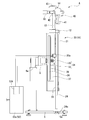
- FIG. 1 is an overall view showing a surgery support system according to a first embodiment of the present invention. It is a perspective view which shows the structure of the operation part in the master operation input device provided in the surgery assistance system of 1st Embodiment of this invention. It is an enlarged view which shows a part of linear motion mechanism of 1st Embodiment of this invention. It is a figure which shows the internal structure of the linear motion mechanism in the operation part of 1st Embodiment of this invention. It is a schematic diagram of the linear motion mechanism with self-weight compensation provided in the linear motion mechanism of 1st Embodiment of this invention. It is a schematic diagram which shows the structure of the modification of embodiment of 1st Embodiment of this invention. It is a schematic diagram which shows the operation input device of 2nd Embodiment of this invention.
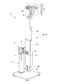
- FIG. 1 is an overall view showing the surgery support system of the present embodiment.
- FIG. 2 is a perspective view illustrating a configuration of an operation unit in a master operation input device provided in the surgery support system.
- FIG. 3 is an enlarged view showing a part of the linear motion mechanism.
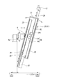
- FIG. 4 is a diagram showing the internal structure of the linear motion mechanism.
- the surgery support system 1 is a master-slave surgery support system, and includes a master operation input device 2 (operation input device), a slave manipulator 50 (operation unit), and a control unit 52. Prepare.
- the master operation input device 2 functions as a master that transmits the movement of the operator Op to the slave manipulator 50, and includes a display unit 3 and an operation unit 4.
- the display unit 3 displays an image of the surgical site of the patient P taken by a camera (not shown) and the vicinity thereof.
- a known display device such as a liquid crystal display or an organic EL display can be appropriately selected and employed.
- the operation unit 4 is communicably connected to the control unit 52, and is disposed on the front side of the display unit 3 so that the operator Op can operate while looking at the display unit 3.
- the operation unit 4 is provided on each of the right hand side and the left hand side of the operator Op.
- the operation unit 4 generally has 6 degrees of freedom. If only position information is input to the position and orientation detection unit 53, the operation unit 4 may have three degrees of freedom. As shown in FIG.
- the operation unit 4 is connected to the base 5, the first arm 8 connected to the base 5 via the first joint 6, and the first arm 8 via the second joint 9.
- a third arm 15 connected to the second arm 13 via the fifth joint 14 and a grip portion 40 connected to the third arm 15 via the sixth joint 16.
- the first joint 6 is a joint that allows the first arm 8 to rotate with respect to the base 5 around a rotation axis extending in the horizontal direction.
- the second joint 9 is a joint that allows the holding member 21 to rotate with respect to the first arm 8 around a rotation axis orthogonal to the rotation axis of the first joint 6.
- the third joint 11 is a linear motion joint in which the first moving body 24 advances and retreats with respect to the holding member 21 in a direction orthogonal to the rotation axes of the second joint 9 and the first joint 6.
- the fourth joint 12 is a joint that allows the second arm 13 to rotate with the linear motion axis direction of the third joint 11 as a rotation axis.
- the fifth joint 14 is a joint that allows the third arm 15 to rotate with respect to the second arm 13 around a rotation axis orthogonal to the rotation axis of the fourth joint 12.
- the sixth joint 16 is a joint that allows the grip portion 40 to rotate with respect to the third arm 15 around a rotation axis orthogonal to the rotation axis of the fifth joint 14.
- the grip portion 40 By placing the grip portion 40 near the position where the rotation axes of the fourth joint 12, the fifth joint 14, and the sixth joint 16 intersect, a gimbal structure is formed, and the posture can be input without changing the position with respect to the fourth joint 12. it can. That is, the rotation axes of the fourth joint 12, the fifth joint 14, and the sixth joint 16 pass through the intersection of the rotation axes of the first joint 6 and the second joint 9 and are parallel to the linear movement axis of the third joint.
- the grip part 40 is arranged so that Thereby, the position of the grip part 40 can be calculated from the movement amounts of the first joint 6, the second joint 9, and the third joint 11.
- the linear motion mechanism with self-weight compensation according to the present embodiment is configured to compensate for the self-weight and maintain the operability of the grip portion 40 regardless of the amount of movement of each joint even if the position of the grip portion 40 is moved. .
- the first joint 6 and the second joint 9 are provided with brakes 7 and 10 that give some resistance when each joint rotates.
- the brake 10 provided in the second joint 9 includes a first pressing plate 8 a fixed to the first arm 8 and a second pressing plate 11 a fixed to the holding member 21.
- a pad X such as felt or rubber
- sliding resistance is generated.
- the brake 7 provided at the first joint 6 is also configured to generate sliding resistance on the same principle as the brake 10 provided at the second joint 9.
- each brake 7 and 10 may be able to adjust the magnitude
- the holding member 21 includes a third joint 11 that changes the distance between the second joint 9 and the fourth joint 12.
- the third joint 11 includes a first moving body 24, a second moving body 26, and a connecting portion 29.
- the holding member 21 is a hollow member connected to the first arm 8 through the second joint 9. Inside the holding member 21, a part of the first moving body 24 and the second moving body 26, and a connecting portion 29 are arranged.
- the holding member 21 is provided with a first guide 22 for holding the first moving body 24 so as to be able to advance and retreat, and a second guide 23 for holding the second moving body 26 so as to be able to advance and retreat.
- the first guide 22 and the second guide 23 are both fixed to the inner surface of the holding member 21.
- the first guide 22 and the second guide 23 are arranged in parallel to each other.
- the holding member 21 can rotate about the second joint 9 as a rotation axis.
- the position of the pivot shaft in the holding member 21 is near the center of gravity of the holding member 21. If the position of the rotation shaft for rotating the holding member 21 is within a range balanced by the frictional force between the holding member 21 and the first arm 8, for example, about 1 centimeter from the center of gravity of the holding member 21. For example, it may
- the first moving body 24 is formed in a rod shape, and is provided with one end of the first moving body 24 protruding from the holding member 21.
- the fourth joint 12 described above is attached to the protruding end of the first moving body 24.
- Each component (refer FIG. 2) from the 2nd arm 13 to the grip part 40 is the attachment target A attached to the 1st mobile body 24 in this embodiment.
- the first moving body 24 extends in the length direction of the first moving body 24 (extends in a linear direction connecting a first intersection point described later and the first center of gravity in the first moving body 24). 25 (first toothpaste).
- the second moving body 26 is formed in a rod shape and is arranged in parallel with the first moving body 24.
- a weight 27 having a predetermined mass is fixed to the second moving body 26.
- the weight 27 is a counterweight for the attachment object A.
- the second moving body 26 extends in the length direction of the second moving body 26 (extends in a linear direction connecting a second intersection point to be described later and the second center of gravity in the second moving body 26). have.
- the connecting portion 29 connects the first moving body 24 and the second moving body 26 so that the weight 27 has a directional component that is opposite to the moving direction of the first moving body 24.
- the connecting portion 29 of this embodiment includes a pinion 30 (gear portion) that meshes with the rack of the first moving body 24 and meshes with the rack of the second moving body 26, and a shaft body 31 that rotatably supports the pinion 30.
- the pinion 30 is supported by the holding member 21 by the shaft body 31. That is, in this embodiment, the 1st moving body 24, the 2nd moving body 26, and the connection part 29 are comprised with the gear of a parallel axis
- the 1st moving body 24 and the 2nd moving body 26 are connected via the pinion 30, the 1st moving body 24 and the 2nd moving body 26 are mutually parallel, and direction is reverse. Move straight in the direction
- the absolute value of the linear movement amount of the first moving body 24 is equal to the absolute value of the linear movement amount of the second moving body 26.
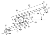
- FIG. 5 is a schematic diagram of the third joint 11 provided in the holding member 21.
- the position and mass of the weight 27 fixed to the second moving body 26 are set such that force moments N1 and N2 schematically shown in FIG. 5 are balanced. That is, The mass of the first moving body 24 with the mounting object A attached is M1, The mass of the second moving body 26 including the weight 27 is M2, The foot position of the perpendicular line from the rotation center of the second joint 9 to the linear motion axis of the first moving body 24 is defined as P1 (first intersection point), The center of gravity position of the object A and the first moving body 24 is P2 (first center of gravity), The foot position of the perpendicular line from the rotation center of the second joint 9 to the linear motion axis of the second moving body 26 is P3 (second intersection point), The center of gravity position P4 (second center of gravity) of the second moving body 26 including the weight 27 is set, The distance between the position P1 and the position P2 when the first moving body 24 is in the initial position (the first intersection of the
- the distance between the position P3 and the position P4 when the second moving body 26 is in the initial position state (the second intersection of the perpendicular from the rotation center of the rotation shaft to the second moving body 26 and the second of the second moving body 26) L2 is the distance between the second center of gravity and the second intersection of the second moving body 26 when the distance from the center of gravity is the shortest, which will be described later.
- M1 g sin ⁇ r1 M2 g sin ⁇ r1 (Formula 1)
- M1 g cos ⁇ (L1 + r1 ⁇ ) M2 g cos ⁇ (L2 + r1 ⁇ ) (Expression 2)
- ⁇ is the rotation angle of the first moving body 24 from the horizontal axis
- r1 is the radius of the pinion 30
- ⁇ is the rotation angle of the pinion 30.
- the initial state of the first moving body 24 and the second moving body 26 is a state in which the linear movement of the third joint 11 is most contracted.
- the distance L1 is a distance when the distance between the position P1 and the position P2 is the shortest
- the distance L2 is a distance when the distance between the position P3 and the position P4 is the shortest.
- the length L1 and the length L2 are the same unit system
- the masses M1 and M2 are the same unit system.
- the position is preferably at the position of the rotation axis of the second joint 9 (which coincides with the shaft body 31 in this embodiment), and the position of the center of gravity is adjusted by adjusting the shape of the holding member 21.
- the moment around the pinion 30 and the moment around the second joint axis 9 are balanced, so that the mounting object A is not affected by the amount of movement of the first moving body 24 and the amount of rotation of the second joint 9.
- the position can be operated without being affected by its own weight.
- the linear motion mechanism 20 may be provided with a brake that gives a slight resistance to the forward and backward movement of the first moving body 24 as necessary.
- the brake is, for example, a brake that generates a sliding resistance between the holding member 21 (see FIG. 4) or the first guide 22 and the first moving body 24, and a sliding resistance between the pinion 30 and the shaft body 31.
- a brake, a slip clutch, etc. to be generated can be appropriately selected and employed. Thereby, even if the balance of the moments of force N1 and N2 is slightly deviated, the error can be absorbed.
- the grip part 40 includes a grip part 41 that is held by the operator Op, and an opening / closing switch part 42 that is used for operating a surgical instrument 51 described later.
- the open / close switch unit 42 opens and closes the forceps piece when a forceps is attached as the surgical instrument 51, and controls energization of the high-frequency knife when the high-frequency knife is attached as the surgical instrument 51. In this way, an operation corresponding to the surgical instrument is input by the switch unit 42.
- the operation unit 4 is provided with sensors for detecting the movement amount and position of each joint and the third joint 11.
- the first joint 6 is provided with an encoder 6 a for detecting the amount of rotation of the first arm 8 relative to the base 5.
- the third joint 11 is provided with an encoder 20 a for detecting the amount of movement of the first moving body 24 with respect to the holding member 21.
- the slave manipulator 50 is connected to the master operation input device 2 via the control unit 52, and is detected by at least each encoder (for example, the encoders 6a and 20a shown in FIG. 4) provided in the operation unit 4. It operates based on the moved amount or position.
- the slave manipulator 50 includes a surgical instrument 51 that operates according to an operation in the master operation input device 2.
- the surgical instrument 51 for example, an endoscope, an endoscopic treatment instrument, and other medical devices or instruments for performing an operation on the patient P can be appropriately selected and employed as necessary.
- the control unit 52 includes a master side control unit 52 a provided in the master operation input device 2 and a slave side control unit 52 b provided in the slave manipulator 50.
- the master-side control unit 52 a includes a position / orientation detection unit 53 (detection unit) electrically connected to each encoder provided in the operation unit 4 of the master operation input device 2.
- the position / orientation detection unit 53 is an absolute value type detection unit, and the position and orientation of the operation unit 4 and the open / close switch unit 42 (FIG. 2) based on the amount of movement from a predetermined origin in each encoder. ) Is detected.
- the slave-side control unit 52b receives the result of detecting the position and posture of the operation unit 4 and the input state to the open / close switch unit 42 in the master-side control unit 52a, and generates a signal for operating the slave manipulator 50. Then, it outputs to the slave manipulator 50 and operates each surgical instrument 51. All of the control unit 52 may be disposed in the master operation input device 2, all of the control unit 52 may be disposed in the slave manipulator 50, or the control unit 52 may be disposed in the master operation input device 2 or the slave manipulator. 50 may be installed separately.
- the operation of the third joint 11, the master operation input device 2, and the surgery support system 1 of this embodiment will be described.
- the first moving body 24 protrudes from the holding member 21 and linearly moves, whereby the distance between the second joint 9 and the fourth joint 12 changes. Since each component from the second arm 13 to the grip part 40 is attached to the fourth joint 12, the force on the first moving body 24 side is increased according to the protruding amount of the first moving body 24. The moment changes.
- the weight 27 provided on the second moving body 26 moves in the opposite direction to the moving body of the first moving body 24. And move.
- the linear motion mechanism 20 is not affected by the mass of the attachment object A and the linear motion mechanism 20 itself, and does not rotate around the second joint 9 and does not expand or contract unless an external force is applied to the grip portion 40.
- the operation input device As described above, according to the linear motion mechanism with self-weight compensation, the operation input device, and the surgery support system 1 of the present embodiment, the first moving body 24 in the third joint 11 regardless of the position of the second joint 9. Regardless of the linear motion position, the state where the moment of force is balanced is maintained. Furthermore, since it is possible to balance both the rotation around the second joint 9 and the expansion and contraction of the linear motion mechanism 20 with a single weight 27, the configuration is simple and the weight is accurately compensated. Although possible, the operation input device can be made small and light.
- first moving body 24 and the second moving body 26 are linearly moved in directions that are parallel to each other and opposite to each other, the first movement is performed when the first moving body 24 and the second moving body 26 are moved.
- the body 24 and the second moving body 26 do not interfere with each other.
- first moving body 24, the second moving body 26 and the connecting portion 29 constitute a so-called rack and pinion mechanism, the movement of the first moving body 24 is reliably transmitted to the second moving body 26.
- the dead weight is compensated with high accuracy.
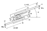
- FIG. 6 is a schematic diagram showing the configuration of this modification.
- the first gear 32 that meshes with the rack 25 of the first moving body 24 and the radius that is smaller than the first gear 32 that meshes with the rack 28 of the second moving body 26 as the gear portions that mesh with the racks 25 and 28.
- a gear portion 34 having a second gear 33 is provided.
- the first gear 32 and the second gear 33 are connected to each other so as to rotate about the same rotation axis.
- the moving amount of the second moving body 26 is smaller than the moving amount of the first moving body 24.
- the mass of the weight 27 attached to the second moving body 26 is set so that torque is balanced as shown in the following formulas 1 and 2.
- M1 g sin ⁇ d1 M2 g sin ⁇ d2 (Expression 1)
- M1 g cos ⁇ (L1 + d1 ⁇ ) M2 g cos ⁇ (L2 + d2 ⁇ ) (Expression 2)
- ⁇ is the rotation angle of the first moving body 24 from the horizontal axis
- d1 is the radius (first radius) of the first gear 32
- d2 is the radius (second radius) of the second gear 33
- ⁇ is the gear portion 34. Is the rotation angle.
- the moment around the gear 34 and the moment around the second joint axis 9 are balanced, so the position of the grip portion 40 is independent of the amount of movement of the first moving body 24 and the amount of rotation of the second joint 9.
- the amount of movement can be reduced to half. Thereby, the collision with the 2nd mobile body 26 and the base 5 can be avoided, and the operation range of the grip part 40 of an operation input device can be enlarged, reducing an
- FIG. 7 is a schematic diagram illustrating an operation unit in the operation input device of the present embodiment.
- a relative value type movement amount detection unit 53A is provided instead of the absolute value type position and orientation detection unit 53 described in the first embodiment. That is, the movement amount detection unit 53A refers to the encoders 6a and 20a provided in the third joint 11, so that the movement amount based on the initialization time of the movement amount detection unit 53A is detected.
- the base 5 is provided with a contact portion 5 a that can contact a part of the first moving body 24. Specifically, the projecting end 24 a of the first moving body 24 that projects from the linear motion mechanism 20 (the end opposite to the side on which the fourth joint 12 is provided) can contact the contact portion 5 a of the base 5. It has become.
- the contact portion 5a provided on the base 5 and the protruding end 24a of the first moving body 24 have an uneven shape that can be fitted to each other.
- the moving amount detecting unit 53A does not directly detect the moving amount of the first moving body 24 using the encoder 20a. Also good. For example, an encoder that detects the amount of movement of the second moving body 26 or the connecting portion 29 may be used.
- the movement amount detection unit 53A When the movement amount detection unit 53A is initialized in the positional relationship in which the first moving body 24 is in contact with the contact portion 5a, the movement amount is set with the positional relationship in which the first moving body 24 is in contact with the contact portion 5a as the origin.
- the posture and the amount of expansion / contraction of the third joint 11 can be calculated by the detection unit 53A.
- the origin can be easily determined with high reproducibility by abutting the protruding end 24a of the first moving body 24 on the abutting portion 5a of the base 5 and initializing the movement amount detecting portion. .
- the operation input device can be fixed by the projecting end 24a of the first moving body 24 coming into contact with the contact portion 5a, the first moving body 24 is moved when the operation input device 4 is transported. Unintentional movement can be prevented.
- the protruding end 24a is at the end of the first moving body 24, and the movable range of the operation input device 4 is not narrowed by disposing the base 5 at the end of the movable range of the first moving body.
- a switch for generating a signal for initializing the movement amount detection unit 53A is provided in the contact portion 5a (see FIG. 7) of the base 5. That is, when the projecting end 24a of the first moving body 24 comes into contact with the contact portion 5a of the base 5, a signal for initializing the movement amount detection unit 53A is detected from the switch. Is output to the unit 53A.
- the step of bringing the protruding end 24a of the first moving body 24 into contact with the contact portion 5a of the base 5 at the start of use of the operation input device is essential, so that the origin is set every time the operation input device is used. Can be determined.
- an operation for determining the origin is given to the operator Op.
- the origin can be determined each time the operation input device is used without being conscious.
- the concrete structure is not restricted to this embodiment,
- the design change etc. of the range which does not deviate from the summary of this invention are included.
- the tooth shape of the rack and pinion may be either a lotus or a mountain.
- it may replace with a rack and pinion and each moving body may be connected with a frictional force.
- the constituent elements shown in the above-described embodiments and modifications can be combined as appropriate.
- the design change etc. with respect to the said specific structure are not limited to the said matter.
- the self-weight can be compensated with high accuracy with a simple configuration.
Landscapes
- Engineering & Computer Science (AREA)
- Health & Medical Sciences (AREA)
- Robotics (AREA)
- Life Sciences & Earth Sciences (AREA)
- Surgery (AREA)
- Mechanical Engineering (AREA)
- Heart & Thoracic Surgery (AREA)
- Nuclear Medicine, Radiotherapy & Molecular Imaging (AREA)
- Biomedical Technology (AREA)
- Medical Informatics (AREA)
- Molecular Biology (AREA)
- Animal Behavior & Ethology (AREA)
- General Health & Medical Sciences (AREA)
- Public Health (AREA)
- Veterinary Medicine (AREA)
- Physics & Mathematics (AREA)
- Automation & Control Theory (AREA)
- General Physics & Mathematics (AREA)
- Manipulator (AREA)
Description
本発明は、自重補償付き直動機構、操作入力装置、及び手術支援システムに関する。
本願は、2012年06月13日に、日本に出願された特願2012-133547号に基づき優先権を主張し、その内容をここに援用する。
本願は、2012年06月13日に、日本に出願された特願2012-133547号に基づき優先権を主張し、その内容をここに援用する。
従来、遠隔操作を行うための装置として、マスタスレーブ方式の遠隔操作装置が知られている。マスタスレーブ方式の遠隔操作装置は、操作者が操作入力をするための操作入力装置と、操作入力装置からの指令によって動作する動作部とを備えるのが一般的である。このとき、操作入力装置や動作部の自重を補償して動作時の負荷を軽減する目的で、バネ、アクチュエータ、あるいはカウンターウエイト等を使用することが知られている。
例えば、特許文献1には、定張力バネを用いて自重を補償することが開示されている。また、特許文献2には、モーターを用いて自重を補償することが開示されている。さらに、特許文献3には、リンク及びバネを用いて自重を補償することが開示されている。
例えば、特許文献1には、定張力バネを用いて自重を補償することが開示されている。また、特許文献2には、モーターを用いて自重を補償することが開示されている。さらに、特許文献3には、リンク及びバネを用いて自重を補償することが開示されている。
しかしながら、バネを用いて自重を補償する構成では、誤差により設計どおりのバネ定数とならない場合があり精度よく自重を補償できない場合がある。また、多軸の遠隔操作装置においては、各軸に対して個別に自重補償付き直動機構を構成する必要がある。その結果、装置が大型化する傾向がある。
本発明は、上述した事情に鑑みてなされたものであって、仰俯角を有する回転軸とその回転軸に連接した直動軸を有する機構において、簡易な構成で精度よく自重を補償できる自重補償付き直動機構、操作入力装置、及び手術支援システムを提供することを目的とする。
上記課題を解決するために、この発明は以下の手段を提案している。 本発明の第一態様に係る自重補償付き直動機構は、取付対象物が取り付けられた第一移動体と、錘が設けられた第二移動体と、前記第一移動体の移動方向と反対に向く方向成分を有して前記錘が移動するように前記第一移動体と前記第二移動体とを連結する連結部と、を保持する保持部材、を備え、前記保持部材は、前記保持部材を回動可能にする回動軸を有し、前記取付対象物が取り付けられた状態の前記第一移動体の質量をM1とし、前記第二移動体の質量をM2とし、前記回動軸の回動中心から前記第一移動体への垂線の第一交点と前記第一移動体の第一重心との距離が一番短い時の、前記第一重心と前記第一移動体における前記第一交点との間の距離をL1とし、前記回動軸の回動中心から前記第二移動体への垂線の第二交点と前記第二移動体の第二重心との距離が一番短い時の、前記第二重心と前記第二移動体における前記第二交点との間の距離をL2としたときに、M2=(L1/L2)×M1を満たす。
本発明の第二態様によれば、上記第一態様において、前記第一移動体と前記第二移動体とは、互いに平行であって向きが逆となる方向へと直線移動してもよい。
本発明の第三態様によれば、上記第一態様、または、上記第二態様において、前記第一移動体は、前記第一移動体における前記第一交点と前記第一重心とを結ぶ直線方向に延びる第一歯竿を有し、前記第二移動体は、前記第二移動体における前記第二交点と前記第二重心とを結ぶ直線方向に延びる第二歯竿を有し、前記連結部は、前記第一歯竿及び前記第二歯竿と噛み合う歯車部を有していてもよい。
本発明の第四態様によれば、上記第三態様において、前記歯車部は、前記第一歯竿と噛み合う第一歯車と、前記第二歯竿と噛み合う第二歯車と、を有し、前記第一歯車の第一半径をd1とし、前記第二歯車の第二半径をd2としたときに、M2=(L1/L2)×M1=(d1/d2)×M1を満していてもよい。
本発明の第五態様によれば、上記第一態様から上記第四態様のいずれか一態様において、前記回動中心は、前記保持部材の重心近傍であってもよい。
本発明の第五態様によれば、上記第一態様から上記第四態様のいずれか一態様において、前記回動中心は、前記保持部材の重心近傍であってもよい。
本発明の第六態様に係る操作入力装置は、上記第一態様から上記第五態様のいずれか一態様の自重補償付き直動機構と、前記自重補償付き直動機構に連結された基台と、前記基台に設けられ前記第一移動体の一部が当接可能な当接部と、前記第一移動体、前記第二移動体、および前記連結部の少なくともいずれかの移動量若しくは位置を検知する相対値方式の検知部と、を備え、前記第一移動体が前記当接部に当接した位置関係において前記検知部が初期化される。
本発明の第七態様に係る手術支援システムは、上記第六態様の操作入力装置と、患者に対して手術を行うための術具を有し前記操作入力装置と接続され少なくとも前記検知部において検知された移動量若しくは位置に基づいて動作する動作部と、を備える。
上記の自重補償付き直動機構、操作入力装置及び手術支援システムによれば、簡易な構成で精度良く自重を補償することができる。
(第1実施形態)
本発明の第1実施形態の自重補償付き直動機構(以下単に「直動機構」と称する。)、操作入力装置、および手術支援システムについて説明する。図1は、本実施形態の手術支援システムを示す全体図である。図2は、手術支援システムに設けられたマスタ操作入力装置における操作部の構成を示す斜視図である。図3は、直動機構の一部を示す拡大図である。図4は、直動機構の内部構造を示す図である。
本発明の第1実施形態の自重補償付き直動機構(以下単に「直動機構」と称する。)、操作入力装置、および手術支援システムについて説明する。図1は、本実施形態の手術支援システムを示す全体図である。図2は、手術支援システムに設けられたマスタ操作入力装置における操作部の構成を示す斜視図である。図3は、直動機構の一部を示す拡大図である。図4は、直動機構の内部構造を示す図である。
図1に示すように、手術支援システム1は、マスタスレーブ方式の手術支援システムであって、マスタ操作入力装置2(操作入力装置)と、スレーブマニピュレータ50(動作部)と、制御部52とを備える。
マスタ操作入力装置2は、操作者Opの動きをスレーブマニピュレータ50に伝達するマスタとして機能し、表示部3と操作部4とを備える。
表示部3は、図示しないカメラによって撮影される患者Pの術部及びその近傍の映像を表示する。表示部3としては、液晶ディスプレイや有機ELディスプレイなどの公知のディスプレイ装置を適宜選択して採用することができる。
図1に示すように、操作部4は、制御部52と通信可能に接続されており、操作者Opが表示部3を見ながら操作できるように表示部3の前側に配置されている。図示してしないが、本実施形態では、操作部4は、操作者Opの右手側と左手側とにそれぞれ設けられている。操作部4のグリップ部40を操作者Opが把持することにより、操作部4の位置姿勢情報が後述する位置姿勢検知部53に入力される。操作部4は、一般的に6自由度を有していることが望ましい。位置情報だけを位置姿勢検知部53に入力するのであれば、操作部4は、3自由度でも構わない。
図2に示すように、操作部4は、基台5と、第一関節6を介して基台5に連結された第一アーム8と、第二関節9を介して第一アーム8に連結された保持部材21と、第三関節11を介して保持部材21に対して直動する第一移動体24と、第四関節12を介して第一移動体24に連結された第二アーム13と、第五関節14を介して第二アーム13に連結された第三アーム15と、第六関節16を介して第三アーム15に連結されたグリップ部40とを備える。
図2に示すように、操作部4は、基台5と、第一関節6を介して基台5に連結された第一アーム8と、第二関節9を介して第一アーム8に連結された保持部材21と、第三関節11を介して保持部材21に対して直動する第一移動体24と、第四関節12を介して第一移動体24に連結された第二アーム13と、第五関節14を介して第二アーム13に連結された第三アーム15と、第六関節16を介して第三アーム15に連結されたグリップ部40とを備える。
第一関節6は、水平方向に延びる回転軸回りに基台5に対して第一アーム8を回転可能とする関節である。
第二関節9は、第一関節6の回転軸と直交する回転軸回りに第一アーム8に対して保持部材21を回転可能とする関節である。
第三関節11は、第二関節9および第一関節6の回転軸と直交する方向に、保持部材21に対して第一移動体24が進退する直動関節である。
第四関節12は、第三関節11の直動軸方向を回転軸として第二アーム13を回転可能とする関節である。
第五関節14は、第四関節12の回転軸と直交する回転軸回りに第二アーム13に対して第三アーム15を回転可能とする関節である。
第六関節16は、第五関節14の回転軸と直交する回転軸回りに第三アーム15に対してグリップ部40を回転可能とする関節である。
第一関節6、第二関節9、及び第三関節11を用いることにより、第一関節6と第二関節9の回転軸が交わる点を中心として、3次元の極座標系を構築することができ、第一移動体24の先端部の位置を定めることができる。
第四関節12、第五関節14、第六関節16の回転軸が交わる位置付近にグリップ部40を配置することによりジンバル構造となり、第四関節12に対して位置が変化することなく姿勢を入力できる。
つまり、第一関節6と第二関節9の回転軸の交点を通り、第三関節の直動軸と平行な軸上に、第四関節12、第五関節14、第六関節16の回転軸が交わるようにグリップ部40を配置する。これにより、グリップ部40の位置を、第一関節6、第二関節9、第三関節11の移動量から計算することができる。
本実施形態の自重補償付き直動機構は、グリップ部40の位置を動かしても、各関節の移動量によらず自重を補償してグリップ部40の操作性を損なわないようにする構成である。
図2及び図3に示すように、第一関節6及び第二関節9には、各関節の回転時に若干の抵抗を付与するブレーキ7,10が設けられている。例えば、図3に示すように、第二関節9に設けられたブレーキ10は、第一アーム8に固定された第一の押圧板8aと、保持部材21に固定された第二の押圧板11aとを有し、第一の押圧板8aと第二の押圧板11aとがフェルトやゴム等のパッドXを介して接することにより、摺動抵抗が発生する。第一関節6に設けられたブレーキ7も、第二関節9に設けられたブレーキ10と同様の原理にて摺動抵抗が発生する構成である。なお、各ブレーキ7,10は、摺動抵抗の大きさを調整できるようになっていてもよい。
図4に示すように、保持部材21は、第二関節9と第四関節12との間の距離を変化させる第三関節11を備えている。第三関節11は、第一移動体24と、第二移動体26と、連結部29とを備えている。
保持部材21は、第二関節9を介して第一アーム8と連結された中空部材である。保持部材21の内部に、第一移動体24及び第二移動体26の一部、並びに連結部29が配されている。また、保持部材21内には、第一移動体24を進退自在に保持する第一ガイド22と、第二移動体26を進退自在に保持する第二ガイド23とが設けられている。本実施形態では、第一ガイド22と第二ガイド23とは、ともに保持部材21の内面に固定されている。また、第一ガイド22と第二ガイド23とは互いに平行に配されている。
保持部材21は、第二関節9を回動軸として回動可能である。保持部材21における前記回動軸の位置は、保持部材21の重心近傍である。保持部材21を回動させるための回動軸の位置は、保持部材21と第一アーム8の摩擦力で釣り合う範囲内であれば、例えば保持部材21の重心から1,2センチメートル程度であれば、ずれていてもよい。
保持部材21は、第二関節9を回動軸として回動可能である。保持部材21における前記回動軸の位置は、保持部材21の重心近傍である。保持部材21を回動させるための回動軸の位置は、保持部材21と第一アーム8の摩擦力で釣り合う範囲内であれば、例えば保持部材21の重心から1,2センチメートル程度であれば、ずれていてもよい。
第一移動体24は、棒状に形成されており、保持部材21から第一移動体24の一端が突出された状態で設けられている。第一移動体24の突出端には上述の第四関節12が取り付けられている。第二アーム13からグリップ部40に至るまでの各構成要素(図2参照)が、本実施形態において第一移動体24に取り付けられる取付対象物Aである。
図4に示すように、第一移動体24は、第一移動体24の長さ方向に延びる(第一移動体24における後述する第一交点と第一重心とを結ぶ直線方向に延びる)ラック25(第一歯竿)を有している。
図4に示すように、第一移動体24は、第一移動体24の長さ方向に延びる(第一移動体24における後述する第一交点と第一重心とを結ぶ直線方向に延びる)ラック25(第一歯竿)を有している。
第二移動体26は、棒状に形成されており、第一移動体24と平行に配されている。第二移動体26には、所定の質量を有する錘27が固定されている。錘27は、取付対象物Aに対するカウンターウエイトである。第二移動体26は、第二移動体26の長さ方向に延びる(第二移動体26における後述する第二交点と第二重心とを結ぶ直線方向に延びる)ラック28(第二歯竿)を有している。
連結部29は、第一移動体24の移動方向と反対に向く方向成分を有して錘27が移動するように第一移動体24と第二移動体26とを連結する。本実施形態の連結部29は、第一移動体24のラックに噛み合い、且つ第二移動体26のラックに噛み合うピニオン30(歯車部)と、ピニオン30を回転自在に支持する軸体31とを備える。ピニオン30は、軸体31によって保持部材21に支持されている。すなわち、本実施形態では、第一移動体24と第二移動体26と連結部29とは、平行軸の歯車を有して構成されている。このように第一移動体24と第二移動体26とがピニオン30を介して連結されているので、第一移動体24と第二移動体26とは、互いに平行であって向きが逆となる方向へと直線移動する。本実施形態では、第一移動体24の直線移動量の絶対値と第二移動体26の直線移動量の絶対値とが等しい。
図5は、保持部材21に設けられた第三関節11の模式図である。
第二移動体26に固定された錘27の位置及び質量は、図5に模式的に示す力のモーメントN1、N2がつりあうように設定される。すなわち、
取付対象物Aが取り付けられた状態の第一移動体24の質量をM1とし、
錘27を含む第二移動体26の質量をM2とし、
第二関節9の回転中心から第一移動体24の直動軸への垂線の足位置をP1(第一交点)とし、
取付対象物Aと第一移動体24の重心位置をP2(第一重心)とし、
第二関節9の回転中心から第二移動体26の直動軸への垂線の足位置をP3(第二交点)とし、
錘27を含む第二移動体26の重心位置P4(第二重心)とし、
第一移動体24が初期位置状態にあるときの位置P1と位置P2の距離(回動軸の回動中心から第一移動体24への垂線の第一交点と第一移動体24の第一重心との距離が後述する一番短い時の、第一重心と第一移動体24における第一交点との間の距離)をL1とし、
第二移動体26が初期位置状態にあるときの位置P3と位置P4の距離(回動軸の回動中心から第二移動体26への垂線の第二交点と第二移動体26の第二重心との距離が後述する一番短い時の、第二重心と第二移動体26における第二交点との間の距離)をL2
としたとき、
M1 g sinφ r1=M2 g sinφ r1・・・(式1)
M1 g cosφ(L1+r1 θ)=M2 g cosφ(L2+r1 θ)・・・(式2)
ただし、φは水平軸からの第一移動体24の回転角、r1はピニオン30の半径、θはピニオン30の回転角である。第一移動体24及び第二移動体26の初期状態とは、第三関節11の直動が一番縮んだ状態とする。このことから、距離L1は、位置P1と位置P2との距離が一番短い時の距離であり、距離L2は、位置P3と位置P4との距離が一番短い時の距離である。
また、長さL1と長さL2とは同一の単位系であり、質量M1とM2とは同一の単位系である。
(式1)、(式2)を解き、
M2=M1、L2=L1を満たすように、錘27の質量および距離L2を設定する。
質量M1及び質量M2に含まれず、保持部材21及び保持部材21に対して移動せずに固定されている第一ガイド22や第二ガイド23、連結部29、エンコーダ20aなどの総質量M3の重心位置は、第二関節9の回転軸(本実施形態では軸体31と一致している)の位置にあることが望ましく、保持部材21の形状を調整して、重心位置を調整している。
これにより、ピニオン30まわりでのモーメントおよび第二関節軸9軸まわりでのモーメントがつりあうため、第一移動体24の移動量および、第二関節9の回転量によらず、取付対象物Aの位置は自重の影響をうけずに動作可能となる。
本実施形態では、直動機構20には、必要に応じて、第一移動体24の進退移動に若干の抵抗を付与するブレーキが設けられていてもよい。ブレーキは、例えば、保持部材21(図4参照)若しくは第一ガイド22と第一移動体24との間に摺動抵抗を発生させるブレーキ、ピニオン30と軸体31との間に摺動抵抗を発生させるブレーキ、保持部材21若しくは第二ガイド23と第二移動体26との間に摺動抵抗を発生させるブレーキ、あるいは第一移動体24と第二移動体26との間に摺動抵抗を発生させるブレーキ、スリップクラッチなどを適宜選択して採用することができる。これにより、力のモーメントN1、N2のバランスが若干ずれていても、誤差を吸収できる。
図1及び図2に示すように、グリップ部40は、操作者Opが把持する把持部41と、後述する術具51の操作に用いる開閉スイッチ部42とを有する。開閉スイッチ部42は、例えば、術具51として鉗子が取り付けられた場合に鉗子片を開閉させ、術具51として高周波ナイフが取り付けられた場合に、高周波ナイフへの通電を制御する。このように、スイッチ部42により、術具に対応した操作が入力される。
また、操作部4には、各関節及び第三関節11の移動量及び位置を検出するためのセンサーが取り付けられている。例えば、図4に示すように、第一関節6には、基台5に対する第一アーム8の回転量を検出するためのエンコーダ6aが設けられている。また、第三関節11には、保持部材21に対する第一移動体24の移動量を検出するためのエンコーダ20aが設けられている。
図1に示すように、スレーブマニピュレータ50は、制御部52を介してマスタ操作入力装置2と接続され、少なくとも操作部4に設けられた各エンコーダ(例えば図4に示すエンコーダ6a、20a)において検知された移動量若しくは位置に基づいて動作する。
スレーブマニピュレータ50は、マスタ操作入力装置2における操作に従って動作する術具51を備えている。術具51は、例えば内視鏡、内視鏡用処置具、その他患者Pに対して手術を行なうための医療機器あるいは医療器具等を必要に応じて適宜選択して採用することができる。
スレーブマニピュレータ50は、マスタ操作入力装置2における操作に従って動作する術具51を備えている。術具51は、例えば内視鏡、内視鏡用処置具、その他患者Pに対して手術を行なうための医療機器あるいは医療器具等を必要に応じて適宜選択して採用することができる。
図1に示すように、制御部52は、マスタ操作入力装置2に設けられたマスタ側制御部52a及びスレーブマニピュレータ50に設けられたスレーブ側制御部52bを有している。
マスタ側制御部52aは、マスタ操作入力装置2の操作部4に設けられた各エンコーダと電気的に接続された位置姿勢検知部53(検知部)を有している。本実施形態では、位置姿勢検知部53は、絶対値型の検知部であり、各エンコーダにおける所定の原点からの移動量に基づいて操作部4の位置及び姿勢、並びに開閉スイッチ部42(図2参照)への入力状態を検知する。
スレーブ側制御部52bは、マスタ側制御部52aにおいて操作部4の位置及び姿勢、並びに開閉スイッチ部42への入力状態を検知した結果が入力され、スレーブマニピュレータ50を動作させるための信号を生成し、スレーブマニピュレータ50へと出力して各術具51を動作させる。
制御部52のすべてがマスタ操作入力装置2に配されていてもよいし、制御部52のすべてがスレーブマニピュレータ50に配されていてもよいし、制御部52がマスタ操作入力装置2やスレーブマニピュレータ50と別体として設置されてもよい。
次に、本実施形態の第三関節11、マスタ操作入力装置2及び手術支援システム1の作用について説明する。
本実施形態では、図4に示すように第一移動体24が保持部材21から突出して直線移動することにより、第二関節9と第四関節12との距離が変化する。第四関節12には、第二アーム13からグリップ部40に至るまでの各構成要素が取り付けられているので、第一移動体24の突出量に応じて、第一移動体24側の力のモーメントが変化する。ここで、第一移動体24の移動量に応じて第二移動体26が移動することにより、第二移動体26に設けられた錘27が、第一移動体24の移動体と反対方向へと移動する。その結果、直動機構20における力のモーメントがつりあった状態が維持されることにより、自重が補償される。すなわち、直動機構20は、取付対象物A及び直動機構20自身の質量の影響を受けず、グリップ部40に外力をかけない限り、第二関節9回りに回転せず、伸縮もしない。
本実施形態では、図4に示すように第一移動体24が保持部材21から突出して直線移動することにより、第二関節9と第四関節12との距離が変化する。第四関節12には、第二アーム13からグリップ部40に至るまでの各構成要素が取り付けられているので、第一移動体24の突出量に応じて、第一移動体24側の力のモーメントが変化する。ここで、第一移動体24の移動量に応じて第二移動体26が移動することにより、第二移動体26に設けられた錘27が、第一移動体24の移動体と反対方向へと移動する。その結果、直動機構20における力のモーメントがつりあった状態が維持されることにより、自重が補償される。すなわち、直動機構20は、取付対象物A及び直動機構20自身の質量の影響を受けず、グリップ部40に外力をかけない限り、第二関節9回りに回転せず、伸縮もしない。
以上説明したように、本実施形態の自重補償付き直動機構、操作入力装置、及び手術支援システム1によれば、第二関節9の位置によらず、第三関節11において第一移動体24が直動位置にもよらず、力のモーメントがつりあった状態が維持される。さらに、第二関節9回りの回転と直動機構20の伸縮との両方に対して1つの錘27でバランスを取ることができるので、構成が簡易なものとなっており、精度良く自重を補償可能でありながら操作入力装置を小型軽量とすることができる。
また、第一移動体24と第二移動体26とが互いに平行であって向きが逆となる方向へ直線移動するので、第一移動体24と第二移動体26との移動時に第一移動体24と第二移動体26とが干渉しない。
また、第一移動体24と第二移動体26と連結部29とによって所謂ラックアンドピニオン機構が構成されているので、第一移動体24の移動が確実に第二移動体26へと伝達され、精度良く自重が補償される。
(変形例)
次に、本実施形態の自重補償付き直動機構(第三関節11)の変形例について説明する。図6は、本変形例の構成を示す模式図である。
本変形例では、ラック25,28にかみ合う歯車部として、第一移動体24のラック25と噛み合う第一歯車32と、第二移動体26のラック28と噛み合い第一歯車32よりも半径が小さな第二歯車33とを有する歯車部34が設けられている。第一歯車32と第二歯車33とは同一の回転軸回りに回転するように互いに連結されている。
本変形例では、第一移動体24の移動量に対して第二移動体26の移動量の方が少ない。その結果、直動機構20において保持部材21からの第二移動体26の突出量が少なく、第三関節11を小型化することができる。
この場合、第二移動体26に取り付けられる錘27の質量は、下記式1,2に示すようにトルクがつりあうように設定される。
M1 g sinφ d1=M2 g sinφ d2・・・(式1)
M1 g cosφ(L1+d1θ)=M2 g cosφ(L2+d2θ)・・・(式2)
ただし、φは水平軸からの第一移動体24の回転角、d1は第一歯車32の半径(第一半径)、d2は第二歯車33の半径(第二半径)、θは歯車部34の回転角である。
M1 g cosφ(L1+d1θ)=M2 g cosφ(L2+d2θ)・・・(式2)
ただし、φは水平軸からの第一移動体24の回転角、d1は第一歯車32の半径(第一半径)、d2は第二歯車33の半径(第二半径)、θは歯車部34の回転角である。
上記式1、2より、第二移動体26に取り付けられる錘27の質量は、M2=(L1/L2)×M1=(d1/d2)×M1を満たしていればよい。
これにより、歯車34まわりでのモーメントおよび第二関節軸9軸まわりでのモーメントがつりあうため、第一移動体24の移動量および、第二関節9の回転量によらず、グリップ部40の位置は自重の影響をうけずに、グリップ部40の位置を適切に入力することができる。
例えば、d1:d2=L1:L2=2:1とすることにより、M2をM1の2倍の質量にすれば、保持部材21からの第二移動体26の突出量を、第一移動体24の移動量の半分に抑えることができる。これにより第二移動体26と基台5との衝突を回避することができ、装置を小型化しつつ、操作入力装置のグリップ部40の動作範囲を大きくすることができる。
これにより、歯車34まわりでのモーメントおよび第二関節軸9軸まわりでのモーメントがつりあうため、第一移動体24の移動量および、第二関節9の回転量によらず、グリップ部40の位置は自重の影響をうけずに、グリップ部40の位置を適切に入力することができる。
例えば、d1:d2=L1:L2=2:1とすることにより、M2をM1の2倍の質量にすれば、保持部材21からの第二移動体26の突出量を、第一移動体24の移動量の半分に抑えることができる。これにより第二移動体26と基台5との衝突を回避することができ、装置を小型化しつつ、操作入力装置のグリップ部40の動作範囲を大きくすることができる。
(第2実施形態)
次に、本発明の第2実施形態の操作入力装置について説明する。なお、以下に説明する実施形態及びその変形例においては、上述の第1実施形態で説明した構成要素と同様の構成要素には同一の符号を付し、重複する説明を省略する。図7は、本実施形態の操作入力装置における操作部を示す模式図である。
次に、本発明の第2実施形態の操作入力装置について説明する。なお、以下に説明する実施形態及びその変形例においては、上述の第1実施形態で説明した構成要素と同様の構成要素には同一の符号を付し、重複する説明を省略する。図7は、本実施形態の操作入力装置における操作部を示す模式図である。
本実施形態では、第1実施形態で説明した絶対値型の位置姿勢検知部53に代えて、相対値型の移動量検知部53Aを備えている。すなわち、第三関節11に設けられたエンコーダ6a、20aを移動量検知部53Aが参照することにより、移動量検知部53Aの初期化時を基準とした移動量が検知される。
また、基台5には、第一移動体24の一部と当接可能な当接部5aが設けられている。具体的には、直動機構20から突出する第一移動体24の突出端24a(第四関節12が設けられた側と反対側の端)が基台5の当接部5aに当接可能となっている。基台5に設けられた当接部5aと第一移動体24の突出端24aとは、互いに嵌合可能な凹凸形状を有している。
また、基台5には、第一移動体24の一部と当接可能な当接部5aが設けられている。具体的には、直動機構20から突出する第一移動体24の突出端24a(第四関節12が設けられた側と反対側の端)が基台5の当接部5aに当接可能となっている。基台5に設けられた当接部5aと第一移動体24の突出端24aとは、互いに嵌合可能な凹凸形状を有している。
第一移動体24、第二移動体26、及び連結部29は互いに連結されているので、移動量検知部53Aは、エンコーダ20aを用いて第一移動体24の移動量を直接検知しなくてもよい。例えば、第二移動体26や連結部29の移動量を検知するエンコーダを用いていてもよい。
このような構成であると、第一移動体24の突出端24aが当接部5aに接している状態では、基台5と直動機構20との相対位置、つまり第一関節6及び第二関節9の関節値、及び第三関節11における第一移動体24の位置が一意に定まる。
第一移動体24が当接部5aに当接した位置関係において移動量検知部53Aが初期化されると、第一移動体24が当接部5aに当接した位置関係を原点として移動量検知部53Aにより第三関節11の姿勢及び伸縮量を算出することができる。
本変形例では、第一移動体24の突出端24aを基台5の当接部5aに当接させて移動量検知部を初期化することにより、原点を容易且つ再現性高く定めることができる。
また、第一移動体24の突出端24aが当接部5aに当接することで、操作入力装置を固定することができるので、操作入力装置4の輸送の際などに、第一移動体24が意図せずに移動してしまうことを防止することができる。この突出端24aは第一移動体24の端部にあり、第一移動体の可動範囲の端部に基台5を配置することにより、操作入力装置4の可動範囲を狭めることがない。
本変形例では、第一移動体24の突出端24aを基台5の当接部5aに当接させて移動量検知部を初期化することにより、原点を容易且つ再現性高く定めることができる。
また、第一移動体24の突出端24aが当接部5aに当接することで、操作入力装置を固定することができるので、操作入力装置4の輸送の際などに、第一移動体24が意図せずに移動してしまうことを防止することができる。この突出端24aは第一移動体24の端部にあり、第一移動体の可動範囲の端部に基台5を配置することにより、操作入力装置4の可動範囲を狭めることがない。
(変形例)
次に、本実施形態の変形例について説明する。
本変形例では、基台5の当接部5a(図7参照)に、移動量検知部53Aを初期化するための信号を発するスイッチが設けられている。すなわち、第一移動体24の突出端24aが基台5の当接部5aに当接した位置関係となったときに、移動量検知部53Aを初期化するための信号がスイッチから移動量検知部53Aへと出力される。
本変形例では、操作入力装置の使用開始時に第一移動体24の突出端24aを基台5の当接部5aに当接させるステップを必須とすることにより、操作入力装置の使用時に毎回原点を定めることができる。また、第一移動体24の突出端24aが基台5の当接部5aに当接している状態を操作入力装置の収納状態として決めておけば、原点を定めるための操作を操作者Opに意識させることなく操作入力装置の使用毎に原点を定めることができる。
以上、本発明の実施形態について図面を参照して詳述したが、具体的な構成はこの実施形態に限られるものではなく、本発明の要旨を逸脱しない範囲の設計変更等も含まれる。
例えば、上述の各実施形態において、ラック及びピニオンの歯形状は、すぐば、はすば、やまばのいずれであってもよい。また、ラックアンドピニオンに代えて、摩擦力によって各移動体を連結するようになっていてもよい。
また、上述の各実施形態及び各変形例において示した構成要素は適宜に組み合わせて構成することが可能である。
なお、上記具体的な構成に対する設計変更等は上記事項には限定されない。
例えば、上述の各実施形態において、ラック及びピニオンの歯形状は、すぐば、はすば、やまばのいずれであってもよい。また、ラックアンドピニオンに代えて、摩擦力によって各移動体を連結するようになっていてもよい。
また、上述の各実施形態及び各変形例において示した構成要素は適宜に組み合わせて構成することが可能である。
なお、上記具体的な構成に対する設計変更等は上記事項には限定されない。
上記の自重補償付き直動機構、操作入力装置及び手術支援システムによれば、簡易な構成で精度良く自重を補償することができる。
1 手術支援システム
2,2A 操作入力装置
3 表示部
4 操作部
5 基台
5a 当接部
6 第一関節
7 ブレーキ
8 第一アーム
9 第二関節
10 ブレーキ
11 第三関節
12 第四関節
13 第二アーム
14 第五関節
15 第三アーム
16 第六関節
20 直動機構
21 保持部材
22 第一ガイド
23 第二ガイド
24 第一移動体
25 ラック(第一歯竿)
26 第二移動体
26a 突出端
27 錘
28 ラック(第二歯竿)
29 連結部
30 ピニオン
31 軸体
32 第一歯車
33 第二歯車
34 歯車部
40 グリップ部
41 把持部
42 開閉スイッチ部
50 スレーブマニピュレータ
51 術具
52 制御部
53 位置姿勢検知部(検知部)
53A 移動量検知部(検知部)
A 取付対象物
P1 連結点
P2 取付点
P3 連結点
P4 取付点
Claims (7)
- 取付対象物が取り付けられた第一移動体と、
錘が設けられた第二移動体と、
前記第一移動体の移動方向と反対に向く方向成分を有して前記錘が移動するように前記第一移動体と前記第二移動体とを連結する連結部と、
を保持する保持部材、
を備え、
前記保持部材は、前記保持部材を回動可能にする回動軸を有し、
前記取付対象物が取り付けられた状態の前記第一移動体の質量をM1とし、前記第二移動体の質量をM2とし、前記回動軸の回動中心から前記第一移動体への垂線の第一交点と前記第一移動体の第一重心との距離が一番短い時の、前記第一重心と前記第一移動体における前記第一交点との間の距離をL1とし、前記回動軸の回動中心から前記第二移動体への垂線の第二交点と前記第二移動体の第二重心との距離が一番短い時の、前記第二重心と前記第二移動体における前記第二交点との間の距離をL2としたときに、M2=(L1/L2)×M1を満たす
自重補償付き直動機構。 - 請求項1に記載の自重補償付き直動機構であって、
前記第一移動体と前記第二移動体とは、互いに平行であって向きが逆となる方向へと直線移動する自重補償付き直動機構。 - 請求項1または2に記載の自重補償付き直動機構であって、
前記第一移動体は、前記第一移動体における前記第一交点と前記第一重心とを結ぶ直線方向に延びる第一歯竿を有し、
前記第二移動体は、前記第二移動体における前記第二交点と前記第二重心とを結ぶ直線方向に延びる第二歯竿を有し、
前記連結部は、前記第一歯竿及び前記第二歯竿と噛み合う歯車部を有する
自重補償付き直動機構。 - 請求項3に記載の自重補償付き直動機構であって、
前記歯車部は、
前記第一歯竿と噛み合う第一歯車と、
前記第二歯竿と噛み合う第二歯車と、
を有し、
前記第一歯車の第一半径をd1とし、前記第二歯車の第二半径をd2としたときに、
M2=(L1/L2)×M1=(d1/d2)×M1を満たす
自重補償付き直動機構。 - 請求項1から4のいずれか一項に記載の自重補償付き直動機構であって、
前記回動中心は、前記保持部材の重心近傍である自重補償付き直動機構。 - 請求項1から5のいずれか一項に記載の自重補償付き直動機構と、
前記自重補償付き直動機構に連結された基台と、
前記基台に設けられ前記第一移動体の一部が当接可能な当接部と、
前記第一移動体、前記第二移動体、および前記連結部の少なくともいずれかの移動量若しくは位置を検知する相対値方式の検知部と、
を備え、
前記第二移動体が前記当接部に当接した位置関係において前記検知部が初期化される
操作入力装置。 - 請求項6に記載の操作入力装置と、
患者に対して手術を行うための術具を有し前記操作入力装置と接続され少なくとも前記検知部において検知された移動量若しくは位置に基づいて動作する動作部と、
を備える手術支援システム。
Priority Applications (3)
| Application Number | Priority Date | Filing Date | Title |
|---|---|---|---|
| CN201380030550.1A CN104364060B (zh) | 2012-06-13 | 2013-06-13 | 带有自重补偿的直线运动机构、操作输入装置及手术支援系统 |
| EP13804124.9A EP2862680A4 (en) | 2012-06-13 | 2013-06-13 | GRAVITY-COMPENSATED LINEAR MOTION MECHANISM, OPERATING INPUT DEVICE, AND SURGICAL ASSISTANCE SYSTEM |
| US14/565,863 US9737996B2 (en) | 2012-06-13 | 2014-12-10 | Linear driving mechanism with self-weight compensation, operation input device, and surgery assistance system |
Applications Claiming Priority (2)
| Application Number | Priority Date | Filing Date | Title |
|---|---|---|---|
| JP2012133547A JP2013255966A (ja) | 2012-06-13 | 2012-06-13 | 自重補償付き直動機構、操作入力装置、及び手術支援システム |
| JP2012-133547 | 2012-06-13 |
Related Child Applications (1)
| Application Number | Title | Priority Date | Filing Date |
|---|---|---|---|
| US14/565,863 Continuation US9737996B2 (en) | 2012-06-13 | 2014-12-10 | Linear driving mechanism with self-weight compensation, operation input device, and surgery assistance system |
Publications (1)
| Publication Number | Publication Date |
|---|---|
| WO2013187469A1 true WO2013187469A1 (ja) | 2013-12-19 |
Family
ID=49758287
Family Applications (1)
| Application Number | Title | Priority Date | Filing Date |
|---|---|---|---|
| PCT/JP2013/066327 Ceased WO2013187469A1 (ja) | 2012-06-13 | 2013-06-13 | 自重補償付き直動機構、操作入力装置、及び手術支援システム |
Country Status (5)
| Country | Link |
|---|---|
| US (1) | US9737996B2 (ja) |
| EP (1) | EP2862680A4 (ja) |
| JP (1) | JP2013255966A (ja) |
| CN (1) | CN104364060B (ja) |
| WO (1) | WO2013187469A1 (ja) |
Cited By (2)
| Publication number | Priority date | Publication date | Assignee | Title |
|---|---|---|---|---|
| WO2017208870A1 (ja) * | 2016-05-30 | 2017-12-07 | ライフロボティクス株式会社 | 直動伸縮機構 |
| EP3225368A4 (en) * | 2014-11-28 | 2018-07-25 | Life Robotics Inc. | Robot arm mechanism |
Families Citing this family (18)
| Publication number | Priority date | Publication date | Assignee | Title |
|---|---|---|---|---|
| FR3016512B1 (fr) * | 2014-01-23 | 2018-03-02 | Universite De Strasbourg | Dispositif d'interface maitre pour systeme endoscopique motorise et installation comprenant un tel dispositif |
| JP6169291B2 (ja) | 2015-02-26 | 2017-07-26 | オリンパス株式会社 | 操作入力装置および医療用マニピュレータシステム |
| WO2017056704A1 (ja) * | 2015-10-01 | 2017-04-06 | ソニー株式会社 | 医療用支持アーム装置及び医療用システム |
| JP2017104451A (ja) * | 2015-12-11 | 2017-06-15 | 川崎重工業株式会社 | 外科手術システム |
| CN108367442B (zh) * | 2016-02-25 | 2021-05-11 | 奥林巴斯株式会社 | 操纵器系统及其控制方法 |
| CN114504387A (zh) * | 2016-06-03 | 2022-05-17 | 柯惠Lp公司 | 用于机器人手术系统的被动轴系统 |
| WO2017210073A1 (en) | 2016-06-03 | 2017-12-07 | Covidien Lp | Passive axis system for robotic surgical systems |
| US9889874B1 (en) * | 2016-08-15 | 2018-02-13 | Clause Technology | Three-axis motion joystick |
| US10849582B2 (en) * | 2016-08-29 | 2020-12-01 | Shimadzu Corporation | Holding mechanism for X-ray imaging apparatus and X-ray imaging apparatus |
| CN106313115B (zh) * | 2016-09-22 | 2018-12-04 | 安徽工程大学 | 一种可拆卸式工业机器人力矩平衡装置及其安装方法 |
| WO2018154559A1 (en) | 2017-02-23 | 2018-08-30 | Human Xtensions Ltd. | Controller for surgical tools |
| KR101887919B1 (ko) | 2017-05-16 | 2018-08-13 | 국방과학연구소 | 전기 구동식 회전 시스템의 중력토크 계측 및 보상방법 |
| AT520763B1 (de) * | 2017-12-21 | 2022-09-15 | Hans Kuenz Gmbh | Kransteuerung |
| EP3788994B1 (en) * | 2018-05-02 | 2023-08-23 | Riverfield Inc. | Intraocular surgery instrument holder |
| CN109394343B (zh) * | 2018-12-29 | 2024-05-24 | 苏州康多机器人有限公司 | 一种全被动型主操作手 |
| CN110253532A (zh) * | 2019-05-30 | 2019-09-20 | 上海建沪鸿达科技有限公司 | 一种纳米纤维生产用的智能监控机器人 |
| CN111365410B (zh) * | 2020-04-16 | 2022-05-17 | 京东方科技集团股份有限公司 | 一种可移动配重装置及c型臂设备 |
| CN114275190B (zh) * | 2022-03-04 | 2022-05-17 | 中国人民解放军战略支援部队航天工程大学 | 一种用于多体卫星变构的三轴正交关节 |
Citations (7)
| Publication number | Priority date | Publication date | Assignee | Title |
|---|---|---|---|---|
| JPS6171987A (ja) * | 1984-09-10 | 1986-04-12 | 神鋼電機株式会社 | 産業用ロボツト |
| JPH024778U (ja) * | 1988-06-24 | 1990-01-12 | ||
| JPH04122583A (ja) * | 1990-09-13 | 1992-04-23 | Fujitsu Ltd | マスタアーム |
| JPH09272082A (ja) | 1996-04-08 | 1997-10-21 | Nippon Steel Corp | 遠隔操作用マスター・アーム装置 |
| JP2001002398A (ja) * | 1999-06-25 | 2001-01-09 | Samsung Electronics Co Ltd | 重量偏在を補うためのバランサを有する貨物積載用ロボット |
| JP2007098507A (ja) | 2005-10-04 | 2007-04-19 | Nagoya Institute Of Technology | 作業補助装置 |
| JP4144021B2 (ja) | 2001-12-14 | 2008-09-03 | 学校法人早稲田大学 | 機械的自重補償装置 |
Family Cites Families (19)
| Publication number | Priority date | Publication date | Assignee | Title |
|---|---|---|---|---|
| JPS6021185Y2 (ja) * | 1980-08-07 | 1985-06-24 | 株式会社明電舎 | パワ−マニプレ−タシステムにおけるマスタ−ア−ム |
| US4442387A (en) * | 1981-11-25 | 1984-04-10 | Unimation, Inc. | Safe programming system for industrial robots |
| NO151575C (no) * | 1982-09-17 | 1985-05-08 | Ole Molaug | Anordning for utbalansering av masse i mekanismer som for eksempel en robotarm |
| US4466387A (en) * | 1983-10-10 | 1984-08-21 | Perry John C | Lubrication means for a two-cycle internal combustion engine |
| JPH02298480A (ja) * | 1989-05-11 | 1990-12-10 | Toshiba Corp | バイラテラルマスタースレーブマニピュレータ |
| US5257998A (en) * | 1989-09-20 | 1993-11-02 | Mitaka Kohki Co., Ltd. | Medical three-dimensional locating apparatus |
| JPH07197960A (ja) * | 1993-12-29 | 1995-08-01 | Bridgestone Corp | ブレーキ機構 |
| US6436107B1 (en) * | 1996-02-20 | 2002-08-20 | Computer Motion, Inc. | Method and apparatus for performing minimally invasive surgical procedures |
| US6210097B1 (en) * | 1999-06-25 | 2001-04-03 | Samsung Electronics Co., Ltd. | Burden loading robot having balancer for compensating for off-center loading of weight |
| US6354167B1 (en) * | 2000-06-26 | 2002-03-12 | The United States Of America As Represented By The Secretary Of The Navy | Scara type robot with counterbalanced arms |
| US8108072B2 (en) * | 2007-09-30 | 2012-01-31 | Intuitive Surgical Operations, Inc. | Methods and systems for robotic instrument tool tracking with adaptive fusion of kinematics information and image information |
| EP1974873B1 (en) * | 2006-01-13 | 2010-03-17 | Nabtesco Corporation | Joint mechanism |
| JP5485656B2 (ja) | 2009-11-06 | 2014-05-07 | 学校法人慶應義塾 | 補償重量切換式荷重補償装置 |
| US8601897B2 (en) * | 2009-11-30 | 2013-12-10 | GM Global Technology Operations LLC | Force limiting device and method |
| JP5429938B2 (ja) | 2010-01-26 | 2014-02-26 | 学校法人慶應義塾 | 自重補償型歩行補助装置 |
| US8689698B2 (en) * | 2011-06-08 | 2014-04-08 | Dennis Shasha | Methods and systems for multi-dimensional motion |
| US9650215B2 (en) * | 2013-05-17 | 2017-05-16 | Intelligrated Headquarters Llc | Robotic carton unloader |
| US9314934B2 (en) * | 2014-02-27 | 2016-04-19 | Disney Enterprises, Inc. | Gravity-counterbalanced robot arm |
| US9623569B2 (en) * | 2014-03-31 | 2017-04-18 | Intelligrated Headquarters, Llc | Autonomous truck loader and unloader |
-
2012
- 2012-06-13 JP JP2012133547A patent/JP2013255966A/ja active Pending
-
2013
- 2013-06-13 EP EP13804124.9A patent/EP2862680A4/en not_active Withdrawn
- 2013-06-13 CN CN201380030550.1A patent/CN104364060B/zh active Active
- 2013-06-13 WO PCT/JP2013/066327 patent/WO2013187469A1/ja not_active Ceased
-
2014
- 2014-12-10 US US14/565,863 patent/US9737996B2/en active Active
Patent Citations (7)
| Publication number | Priority date | Publication date | Assignee | Title |
|---|---|---|---|---|
| JPS6171987A (ja) * | 1984-09-10 | 1986-04-12 | 神鋼電機株式会社 | 産業用ロボツト |
| JPH024778U (ja) * | 1988-06-24 | 1990-01-12 | ||
| JPH04122583A (ja) * | 1990-09-13 | 1992-04-23 | Fujitsu Ltd | マスタアーム |
| JPH09272082A (ja) | 1996-04-08 | 1997-10-21 | Nippon Steel Corp | 遠隔操作用マスター・アーム装置 |
| JP2001002398A (ja) * | 1999-06-25 | 2001-01-09 | Samsung Electronics Co Ltd | 重量偏在を補うためのバランサを有する貨物積載用ロボット |
| JP4144021B2 (ja) | 2001-12-14 | 2008-09-03 | 学校法人早稲田大学 | 機械的自重補償装置 |
| JP2007098507A (ja) | 2005-10-04 | 2007-04-19 | Nagoya Institute Of Technology | 作業補助装置 |
Non-Patent Citations (1)
| Title |
|---|
| See also references of EP2862680A4 * |
Cited By (2)
| Publication number | Priority date | Publication date | Assignee | Title |
|---|---|---|---|---|
| EP3225368A4 (en) * | 2014-11-28 | 2018-07-25 | Life Robotics Inc. | Robot arm mechanism |
| WO2017208870A1 (ja) * | 2016-05-30 | 2017-12-07 | ライフロボティクス株式会社 | 直動伸縮機構 |
Also Published As
| Publication number | Publication date |
|---|---|
| CN104364060B (zh) | 2017-03-22 |
| US9737996B2 (en) | 2017-08-22 |
| US20150090065A1 (en) | 2015-04-02 |
| JP2013255966A (ja) | 2013-12-26 |
| CN104364060A (zh) | 2015-02-18 |
| EP2862680A4 (en) | 2016-04-06 |
| EP2862680A1 (en) | 2015-04-22 |
Similar Documents
| Publication | Publication Date | Title |
|---|---|---|
| WO2013187469A1 (ja) | 自重補償付き直動機構、操作入力装置、及び手術支援システム | |
| CN112423694B (zh) | 机器人手臂结构和包括该机器人手臂结构的手术机器人的机械手 | |
| JP5916320B2 (ja) | 遠隔操縦装置 | |
| JP5855423B2 (ja) | 手術支援装置 | |
| CN107961078A (zh) | 手术机器人系统及其手术器械 | |
| US11058502B2 (en) | Support arm device | |
| US20210393350A1 (en) | Parallel link device, master-slave system, and medical master-slave system | |
| CN115300110B (zh) | 内窥镜手术控制系统 | |
| WO2019056871A1 (zh) | 手术机器人系统 | |
| CN113194869B (zh) | 手术机器人装置和手术机器人装置的驱动方法 | |
| CN104622585A (zh) | 一种腹腔镜微创手术机器人主从同构式遥操作主手 | |
| CY1111710T1 (el) | Ρομποτικο χειρουργικο συστημα για τη διενεργεια ιατρικων πραξεων ελαχιστης επεμβατικοτητας | |
| JPWO2014156250A1 (ja) | マスタスレーブシステム | |
| KR102221090B1 (ko) | 사용자 인터페이스 장치, 수술 로봇 장치의 마스터 콘솔 및 그 조작방법 | |
| JP6875495B2 (ja) | 手術マニピュレータの操作装置およびロボット支援手術システム | |
| WO2014021218A1 (ja) | 術具及び医療用マニピュレータ | |
| JP2023030101A (ja) | ロボットマニピュレータを制御するためのコンソール | |
| WO2004041485A1 (ja) | 多節スライダ・リンクによる屈曲機構 | |
| KR20200045352A (ko) | 마스터 로봇 및 그 제어 방법 | |
| JPWO2020044838A1 (ja) | パラレルワイヤ装置、パラレルワイヤシステム、医療用ロボットの操作装置、移動式投影装置、及び移動式撮影装置 | |
| KR20140132113A (ko) | 백래시 보상 방법 및 백래시 보상값 산출식 생성 방법 | |
| CN119097424A (zh) | 操作主手、医生控制台以及腹腔内窥镜手术机器人 | |
| JP6567771B2 (ja) | マニピュレータシステム | |
| CN222032590U (zh) | 操作主手、医生控制台以及腹腔内窥镜手术机器人 | |
| CN107997823A (zh) | 一种外科手术机器人操作端力传感装置 |
Legal Events
| Date | Code | Title | Description |
|---|---|---|---|
| 121 | Ep: the epo has been informed by wipo that ep was designated in this application |
Ref document number: 13804124 Country of ref document: EP Kind code of ref document: A1 |
|
| NENP | Non-entry into the national phase |
Ref country code: DE |