WO2013187697A1 - 인라인 에이징 장치 - Google Patents
인라인 에이징 장치 Download PDFInfo
- Publication number
- WO2013187697A1 WO2013187697A1 PCT/KR2013/005205 KR2013005205W WO2013187697A1 WO 2013187697 A1 WO2013187697 A1 WO 2013187697A1 KR 2013005205 W KR2013005205 W KR 2013005205W WO 2013187697 A1 WO2013187697 A1 WO 2013187697A1
- Authority
- WO
- WIPO (PCT)
- Prior art keywords
- magazine
- heating zone
- air
- zone
- heating
- Prior art date
- Legal status (The legal status is an assumption and is not a legal conclusion. Google has not performed a legal analysis and makes no representation as to the accuracy of the status listed.)
- Ceased
Links
Images



Classifications
-
- G—PHYSICS
- G01—MEASURING; TESTING
- G01R—MEASURING ELECTRIC VARIABLES; MEASURING MAGNETIC VARIABLES
- G01R31/00—Arrangements for testing electric properties; Arrangements for locating electric faults; Arrangements for electrical testing characterised by what is being tested not provided for elsewhere
- G01R31/28—Testing of electronic circuits, e.g. by signal tracer
-
- H—ELECTRICITY
- H10—SEMICONDUCTOR DEVICES; ELECTRIC SOLID-STATE DEVICES NOT OTHERWISE PROVIDED FOR
- H10P—GENERIC PROCESSES OR APPARATUS FOR THE MANUFACTURE OR TREATMENT OF DEVICES COVERED BY CLASS H10
- H10P72/00—Handling or holding of wafers, substrates or devices during manufacture or treatment thereof
- H10P72/04—Apparatus for manufacture or treatment
- H10P72/0431—Apparatus for thermal treatment
- H10P72/0434—Apparatus for thermal treatment mainly by convection
-
- H—ELECTRICITY
- H10—SEMICONDUCTOR DEVICES; ELECTRIC SOLID-STATE DEVICES NOT OTHERWISE PROVIDED FOR
- H10P—GENERIC PROCESSES OR APPARATUS FOR THE MANUFACTURE OR TREATMENT OF DEVICES COVERED BY CLASS H10
- H10P72/00—Handling or holding of wafers, substrates or devices during manufacture or treatment thereof
- H10P72/30—Handling or holding of wafers, substrates or devices during manufacture or treatment thereof for conveying, e.g. between different workstations
- H10P72/33—Handling or holding of wafers, substrates or devices during manufacture or treatment thereof for conveying, e.g. between different workstations into and out of processing chamber
- H10P72/3314—Continuous loading and unloading into and out of a processing chamber, e.g. transporting belts within processing chambers
Definitions
- the present invention relates to an in-line aging apparatus, and more particularly, it is possible to increase the production yield by allowing the injected magazine to be automatically transported and discharged through the heating process and the cooling process, as well as the process time and work force.
- An inline aging device which can be reduced more drastically.
- Substrates or other electronic products undergo an aging test for a period of time over a predetermined temperature range to test whether the operating characteristics change over time.
- a magazine accommodating a substrate is conventionally inserted into an oven equipped with a forklift by using a forklift rather than an automatic process into an oven, and then again using a forklift after a predetermined time. Since the aging test has been carried out by the method of pulling out, the production yield is reduced, and the process time and workforce have been increased, so research and development are required.
- An object of the present invention is to increase the production yield by automatically discharged through the heating process and cooling process while the magazine is transferred automatically, as well as to reduce the process time and work force significantly more than conventional To provide.
- the object includes: an apparatus body for forming a place where an aging process for an aging workpiece is performed; A magazine input part provided in an inlet area of the apparatus main body and into which a magazine containing the workpiece is inserted; A heating zone provided in the apparatus main body and for heating a magazine past the magazine input part to a predetermined temperature range; A cooling zone for cooling the magazine in which the heating is completed through the heating zone to a temperature of room temperature; And it is achieved by the in-line aging device characterized in that it comprises a magazine discharge portion through which the cooling is completed through the cooling zone magazine is discharged.
- the magazine inlet, the heating zone, the cooling zone and the magazine outlet in the apparatus body may form a work line inlined by a chain conveyor.
- a blower provided on an upper side of the heating zone to circulate air in the heating zone;
- a heater disposed around the blower and configured to heat air in the heating zone;
- an air circulation passage that forms a path through which air heated by the heater is circulated by the blower, and a plurality of air discharge holes through which air is discharged on one side wall is formed.
- the air circulation passage portion may be formed to be narrower than the upper portion, and the air discharged through the air discharge holes is returned to the opposite sides of the air discharge holes in the heating zone to be recycled toward the blower. Holes may be formed.
- the air discharge hole may have a circular shape, and the air return hole may have a long hole shape.
- a service automatic door provided to be opened and closed by power installed in the heating zone; And a sliding manual door provided to be opened and closed with no power installed in the cooling zone.
- the boundary between the magazine inlet, the heating zone, the cooling zone and the magazine outlet may be further provided with a sliding automatic door that is automatically opened and closed at a predetermined time at the corresponding position.
- the magazine input unit, the heating zone and the cooling zone may be provided with a plurality of position sensors for sensing the position of the magazine, respectively, the magazine may be provided with a temperature sensor, which is coupled to one side of the device body The position of the magazine or the temperature of the magazine may be output to the display unit.
- the injected magazine is automatically transferred and discharged through the heating process and the cooling process, thereby increasing the production yield, as well as reducing the time required for the process and the work force.
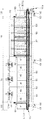
- FIG. 1 is a schematic perspective view of an inline aging apparatus according to an embodiment of the present invention.
- FIG. 2 and 3 are planar and side projection structural diagrams for FIG. 1, respectively.
- FIG. 4 is a longitudinal cross-sectional view of FIG. 1 for a heating zone region.
- blower 132 heater
- cooling zone 150 magazine outlet
- FIG. 1 is a schematic perspective view of an inline aging apparatus according to an embodiment of the present invention
- FIGS. 2 and 3 are planar and side projection structural views of FIG. 1, respectively
- FIG. 4 is a longitudinal section of FIG. 1 with respect to a heating zone region. It is a structural diagram.
- In-line aging device of the present embodiment is a technology for curing the PCB board (Board) applied to the vehicle navigation (Car Navigation), such as GM, HMC, BYOM and curing at high temperature, PCB curing of the PCB production line It can be applied to an oven.
- the object applied to the aging apparatus of the present embodiment is not limited to the above-described PCB board, it can be a substrate of various applications.
- the inline aging apparatus of the present embodiment includes a device main body 110, a magazine inlet 120, a heating zone 130, a cooling zone 140, and a magazine.
- the discharge unit 150 is included.
- FIG. 1 schematically shows an outline of an inline aging apparatus, which includes a magazine inlet 120, a heating zone 130, a cooling zone 140, and a magazine outlet 150 in the apparatus body 110. Is formed and the introduced magazine is automatically transferred by a chain conveyor (chain conveyor) 101 to form an inlined (inline) working line.
- a chain conveyor chain conveyor
- the magazine injected into the chain conveyor 101 passes through the heating zone 130, the cooling zone 140, and the magazine discharge unit 150 along the chain conveyor 101 to automatically complete the aging process.
- the chain conveyor 101 is rotated in one direction by the chain drive unit 101a shown in FIG. 3 to transport the magazine.
- the injected magazine is automatically transferred and discharged through the heating process and the cooling process, thereby increasing the production yield and significantly reducing the process time and work force than before.
- the apparatus main body 110 refers to the exterior cabinet of the inline aging apparatus of this embodiment, and forms a place where an aging process for an aging workpiece is performed.
- the aging workpiece may be a PCB board applied to car navigation, and the boards may be accommodated in 34 magazines and transferred through the magazines, for example.
- the magazine is a transfer medium that accommodates and transfers a plurality of boards.
- the magazine may be provided with a temperature sensor (not shown), and the temperature in the magazine may be displayed through the temperature sensor. Of course, the temperature in the magazine detected by the temperature sensor may be displayed through the display unit 160.
- the magazine may proceed with an aging process for the PCB board while a total of 13 are sequentially transferred.
- these figures are only one example, and therefore, the scope of the present invention is not limited to these figures.
- the device body 110 may be made of a rigid metal material, for example, stainless steel.
- a plurality of feet 102 and 103 are provided in the lower portion of the apparatus main body 110.
- the first foot 102 may be for rolling movement and the second foot 103 may be for a stopper.
- the magazine inlet 120 is provided at the inlet area of the apparatus main body 110 and forms a place where the magazine is inserted.
- the magazine may be loaded while being manually loaded in the magazine input unit 120 or may be loaded while being automatically loaded.
- the line may be laid or constructed using a robot so that the magazine is automatically transferred from the magazine outlet 150 to the magazine inlet 120.
- the heating zone 130 is a zone disposed at the rear of the magazine inlet 120 in the apparatus main body 110.
- the heating zone 130 is a place where the magazine past the magazine inlet 120 is heated to a predetermined temperature range. Achieve. That is, the bonded PCB board is cured in a high temperature state by staying in the heating zone 130 for a predetermined time while mounted in the magazine.
- a blower 131 In the heating zone 130, a blower 131, a heater 132, and an air circulation passage 133 may be disposed in the heating zone 130 so that the magazines entered into the heating zone 130 may be heated in the heating zone 130. It is provided.
- the blower 131 is provided at an upper side of the heating zone 130 to circulate air in the heating zone 130.
- the heater 132 is disposed around the blower 131 and serves to heat air in the heating zone 130.
- the blower 131 is rotated by the blower motor 131a to generate a flow of air.
- the heater 132 is replaceably disposed in the heater housing 132a formed on the upper surface of the apparatus main body 110. In the present embodiment, three pairs of the blower 131 and the heater 132 are disposed in the heating zone 130, which is one embodiment, and the scope of the present invention is not limited thereto.
- the air circulation passage part 133 forms a path through which the air generated by the blower 131 is circulated by the heater 132.
- a plurality of air discharge holes 133a through which air circulated along the air circulation flow path part 133 is discharged are formed at one side wall of the air circulation flow path part 133 facing the magazine side.
- the air circulation passage 133 since the air flows down from the upper through the air circulation passage 133, the air circulation passage 133 is formed to be narrower than the upper side. Only then is the flow rate faster toward the bottom, so that the amount of air discharged to the magazine can be uniformly distributed in the upper and lower portions.
- a plurality of air return holes 171a are formed at opposite sides of the air discharge holes 133a, that is, the air discharged through the air discharge holes 133a is returned and recycled toward the blower 131 on the inner wall of the service automatic door 171. do.
- the air discharged through the air discharge holes 133a for example, air having a temperature range of about 110 degrees ⁇ 5 degrees can heat the board in the magazine, and is returned back through the air return holes 171a.
- the air discharge hole 133a may have a circular shape, and the air return hole 171a may have a long hole shape.
- the cooling zone 140 serves to cool a magazine in which heating is completed through the heating zone 130 to a temperature of room temperature.
- the cooling zone 140 prevents injury to the operator by cooling the magazine heated in the heating zone 130.
- a general atmosphere to a blower (not shown)
- a plurality of cooling holes 141 are provided at one side of the apparatus main body 110 in which the cooling zone 140 is located. Can be formed).
- one side of the heating zone 130 is provided with a service automatic door 171
- one side of the cooling zone 140 is provided with a sliding manual door 172 parallel to the service automatic door 171.
- the service automatic door 171 is provided to be opened and closed upward in the 50 degree direction by power, for example, the power of the actuator. This service automatic door 171 is applied for internal repair, that is, maintenance.
- the opening manual door 172 does not move the magazine discharged as a door that is opened and closed by a manual opening method instead of power, the magazine may be filled in the cooling zone 140 and thus the magazine may be manually inserted. Can be prepared for ejection.
- the opening and closing manual door 172 may be utilized as a passage for maintenance.
- Magazine discharge unit 150 forms a place where the cooling is completed through the cooling zone 140 is discharged.
- the first to third sliding automatic door that is automatically opened and closed at a predetermined time interval at the corresponding position (181--183) is provided.
- the first to third sliding automatic doors (181 to 183) have a structure that opens automatically at a predetermined time, but if there is no magazine in front of the first to third sliding automatic doors (181 to 183) do.
- Such a structure is disposed in front of the first to third sliding automatic doors (181 to 183) and a photo sensor (not shown) for checking the presence or absence of a magazine to detect whether there is a magazine at a corresponding position, and an optical sensor for checking the presence of a magazine. It can be implemented simply by applying a controller (not shown) for controlling the operation of the first to third sliding automatic doors (181 to 183) based on the information.
- the temperature change of the heating zone 130 may be kept to a minimum.
- a plurality of position sensors 161 are provided in the magazine input unit 120, the heating zone 130, the cooling zone 140, and the magazine discharge unit 150 to sense the position of the magazine. do.
- the display unit 160 provided at one side of the apparatus main body 110 may display where the magazines are located in the aging device by signals from the plurality of position sensors 161.
- the display unit 160 may be implemented such that the temperature of the magazine is displayed on the screen due to the temperature sensor provided in the magazine.
- a magazine containing a plurality of substrates is introduced into the magazine inlet 120.
- the magazine loaded while being loaded into the magazine input unit 120 enters the inside of the heating zone 130 at a predetermined time, for example, once every 4 minutes and 50 seconds, and enters the heating zone 130.
- the first sliding automatic door 181 is closed.
- the charged magazine is placed within a predetermined temperature range in the heating zone 130 for a predetermined time.
- the magazine stays while moving in the heating zone 130, for example, for a total of 29 minutes from entering the heating zone 130 to the cooling zone 140.
- this heating time may vary depending on the time condition of the aging test, but in this case, the heating proceeds in this manner.
- the bonded PCB board in the magazine is cured in a high temperature state.
- the second sliding automatic door 182 at the boundary between the heating zone 130 and the cooling zone 140 is opened, whereby the magazine in which the heating is completed enters the cooling zone 140.
- the magazine reached the cooling zone 140 is cooled by the normal air is blown by the operation of a blower (not shown), the magazine is cooled by passing through the cooling zone 140, the magazine discharge unit 150 Discharged through.
- the input magazine is automatically transported and discharged through the heating process and the cooling process, thereby increasing the production yield, and significantly increasing the process time and work force than before. Can be reduced.
Landscapes
- Engineering & Computer Science (AREA)
- General Engineering & Computer Science (AREA)
- Physics & Mathematics (AREA)
- General Physics & Mathematics (AREA)
- Warehouses Or Storage Devices (AREA)
Abstract
본 발명은 인라인 에이징 장치에 관한 것으로서, 에이징(aging) 작업대상물에 대한 에이징 공정이 진행되는 장소를 형성하는 장치 본체; 상기 장치 본체의 입구 영역에 마련되며, 상기 작업대상물 다수 개가 수용되는 매거진(magazine)이 투입되는 매거진 투입부; 상기 장치 본체 내에 마련되며, 상기 매거진 투입부를 지난 매거진을 미리 결정된 온도 범위로 히팅(heating)하는 히팅 존(heating zone); 상기 히팅 존을 통해 히팅이 완료된 매거진을 상온의 온도로 쿨링(cooling)하는 쿨링 존(cooling zone); 및 상기 쿨링 존을 통해 쿨링이 완료된 매거진이 배출되는 매거진 배출부를 포함한다.
Description
본 발명은, 인라인 에이징 장치에 관한 것으로서, 보다 상세하게는, 투입된 매거진이 자동으로 이송되면서 히팅 공정 및 냉각 공정을 거쳐 배출되도록 함으로써 생산 수율을 증가시킬 수 있음은 물론 공정 소요시간 및 작업인력을 종래보다 현격하게 감소시킬 수 있는 인라인 에이징 장치에 관한 것이다.
기판이나 기타 전자 제품은 소정 온도범위에서 일정 시간 동안 에이징 테스트(aging test)를 거쳐 시간의 경과에 따라 작동 특성이 변화하는지를 테스트하는 과정을 거치게 된다.
이러한 에이징 테스트를 위하여, 종래에는 기판 등을 수용한 매거진이 오븐에 자동 공정으로 투입되어 진행되기 보다는 지게차 등을 이용하여 매거진을 별도로 구비된 오븐에 삽입시킨 후 일정시간 경과 후 다시 지게차 등을 이용하여 꺼내는 방식으로 에이징 테스트가 진행되어 왔기 때문에 생산 수율이 감소되고, 공정 소요시간 및 작업인력이 증가하는 문제점이 발생되어 왔으므로 이에 대한 연구 개발이 요구된다.
본 발명의 목적은, 투입된 매거진이 자동으로 이송되면서 히팅 공정 및 냉각 공정을 거쳐 배출되도록 함으로써 생산 수율을 증가시킬 수 있음은 물론 공정 소요시간 및 작업인력을 종래보다 현격하게 감소시킬 수 있는 인라인 에이징 장치를 제공하는 것이다.
상기 목적은, 에이징(aging) 작업대상물에 대한 에이징 공정이 진행되는 장소를 형성하는 장치 본체; 상기 장치 본체의 입구 영역에 마련되며, 상기 작업대상물이 수용된 매거진(magazine)이 투입되는 매거진 투입부; 상기 장치 본체 내에 마련되며, 상기 매거진 투입부를 지난 매거진을 미리 결정된 온도 범위로 히팅(heating)하는 히팅 존(heating zone); 상기 히팅 존을 통해 히팅이 완료된 매거진을 상온의 온도로 쿨링(cooling)하는 쿨링 존(cooling zone); 및 상기 쿨링 존을 통해 쿨링이 완료된 매거진이 배출되는 매거진 배출부를 포함하는 것을 특징으로 하는 인라인 에이징 장치에 의해 달성된다.
상기 장치 본체 내에서 상기 매거진 투입부, 상기 히팅 존, 상기 쿨링 존 및 상기 매거진 배출부는 체인 컨베이어(chain conveyor)에 의해 인라인(inline)화된 작업라인을 형성할 수 있다.
상기 히팅 존의 상부 일측에 마련되어 상기 히팅 존 내에서 공기를 순환시키는 블로어(blower); 상기 블로어의 주변에 배치되며, 상기 히팅 존 내의 공기를 히팅하는 히터(heater); 및 상기 히터에 의해 히팅된 공기가 상기 블로어에 의해 순환되는 경로를 형성하되 일측벽에 공기가 토출되는 다수의 공기토출홀이 형성되는 공기 순환 유로부를 더 포함할 수 있다.
상기 공기 순환 유로부는 상부보다 하부 쪽이 좁게 형성될 수 있으며, 상기 히팅 존 내에서 상기 공기토출홀들의 맞은편에는 상기 공기토출홀들을 통해 토출된 공기가 리턴되어 상기 블로어 쪽으로 재순환되는 다수의 공기리턴홀이 형성될 수 있다.
상기 공기토출홀은 원형 형상을 가지며, 상기 공기리턴홀은 장공의 형상을 가질 수 있다.
상기 히팅 존에 설치된 동력에 의해 개폐 가능하게 마련되는 서비스 자동도어; 및 상기 쿨링 존에 설치된 무동력으로 개폐 가능하게 마련되는 여닫이식 수동도어를 더 포함할 수 있다.
상기 매거진 투입부, 상기 히팅 존, 상기 쿨링 존 및 상기 매거진 배출부 사이의 경계에는 해당 위치에서 미리 결정된 시간에 자동으로 개폐되는 슬라이딩 자동도어가 더 마련될 수 있다.
상기 슬라이딩 자동도어의 앞쪽에 배치되어 해당 위치에 상기 매거진이 있는지의 여부를 감지하는 매거진 유무 확인용 광센서; 및 상기 매거진 유무 확인용 광센서의 정보에 기초하여 상기 슬라이딩 자동도어의 동작을 컨트롤하는 컨트롤러를 더 포함할 수 있다.
상기 매거진 투입부, 상기 히팅 존 및 상기 쿨링 존에는 각각 상기 매거진의 위치를 감지하는 다수의 위치센서가 마련될 수 있으며, 상기 매거진에는 온도센서가 마련될 수 있으며, 상기 장치 본체의 일측에 결합되는 디스플레이부에는 상기 매거진의 위치 또는 상기 매거진의 온도가 출력될 수 있다.
본 발명에 따르면, 투입된 매거진이 자동으로 이송되면서 히팅 공정 및 냉각 공정을 거쳐 배출되도록 함으로써 생산 수율을 증가시킬 수 있음은 물론 공정 소요시간 및 작업인력을 종래보다 현격하게 감소시킬 수 있는 효과가 있다.
도 1은 본 발명의 일 실시예에 따른 인라인 에이징 장치의 개략적인 사시도이다.
도 2 및 도 3은 각각 도 1에 대한 평면 및 측면 투영 구조도이다.
도 4는 히팅 존 영역에 대한 도 1의 종단면 구조도이다.
<부호의 설명>
110 : 장치 본체 101 : 체인 컨베이어
120 : 매거진 투입부 130 : 히팅 존
131 : 블로어 132 : 히터
133 : 공기 순환 유로부 133a : 공기토출홀
140 : 쿨링 존 150 : 매거진 배출부
160 : 디스플레이부 171 : 서비스 자동도어
171a : 공기리턴홀 172 : 여닫이식 수동도어
181~183 : 제1 내지 제3 슬라이딩 자동도어
이하, 첨부도면을 참조하여 본 발명의 바람직한 실시예를 설명한다.
도 1은 본 발명의 일 실시예에 따른 인라인 에이징 장치의 개략적인 사시도, 도 2 및 도 3은 각각 도 1에 대한 평면 및 측면 투영 구조도, 그리고 도 4는 히팅 존 영역에 대한 도 1의 종단면 구조도이다.
본 실시예의 인라인 에이징 장치는 GM, HMC, BYOM 등의 차량 네비게이션(Car Navigation)에 적용되는 PCB 보드(Board)를 본딩(Bonding)한 다음에 고온 상태에서 경화시키는 기술로서, PCB 생산라인의 PCB 경화용 오븐(Oven)에 적용될 수 있다. 물론, 본 실시예의 에이징 장치에 적용되는 대상은 전술한 PCB 보드에 국한되는 것은 아니므로, 다양한 용도의 기판이 될 수 있다.
참고로, 종전까지는 개별 인력에 의해 매거진(Magazine, 도 3 참조)을 수동으로 경화로(Oven)에 넣어 생산하였던 방식을 인라인(Inline)으로 구축함으로써 생산 수율의 증대는 물론이고, 공정 소요시간 및 작업인력의 절감 효과를 제공할 수 있다.
도 1 내지 도 4를 참조하면, 본 실시예의 인라인 에이징 장치는, 장치 본체(110), 매거진 투입부(120), 히팅 존(heating zone, 130), 쿨링 존(cooling zone, 140), 그리고 매거진 배출부(150)를 포함한다.
도 1은 인라인 에이징 장치의 외형을 개략적으로 도시한 것으로, 인라인 에이징 장치는 장치 본체(110) 내에 매거진 투입부(120), 히팅 존(130), 쿨링 존(140) 및 매거진 배출부(150)가 형성되어 투입된 매거진이 체인 컨베이어(chain conveyor, 101)에 의해 자동 이송되면서 인라인(inline)화된 작업라인을 형성한다.
다시 말해, 체인 컨베이어(101)에 투입된 매거진은 체인 컨베이어(101)를 따라 히팅 존(130), 쿨링 존(140) 및 매거진 배출부(150)를 지나면서 에이징 공정이 자동으로 완료된다. 체인 컨베이어(101)는 도 3에 도시된 체인 구동부(101a)에 의해 일 방향으로 회전되면서 매거진을 이송시킨다.
이처럼 투입된 매거진이 자동으로 이송되면서 히팅 공정 및 냉각 공정을 거쳐 배출되도록 함으로써 생산 수율을 증가시킬 수 있음은 물론 공정 소요시간 및 작업인력을 종래보다 현격하게 감소시킬 수 있게 된다.
장치 본체(110)는 본 실시예의 인라인 에이징 장치의 외관 캐비닛을 가리키며, 에이징(aging) 작업대상물에 대한 에이징 공정이 진행되는 장소를 형성한다.
여기서, 에이징 작업대상물이란 전술한 바와 같이, 차량 네비게이션(Car Navigation)에 적용되는 PCB 보드일 수 있으며, 이러한 보드는 예컨대, 34개씩 매거진에 수용되어 매거진을 통해 이송될 수 있다. 매거진은 보드를 다수 개 수용하여 이송시키는 이송매체로서, 매거진에는 온도센서(미도시)가 마련될 수 있으며, 온도센서를 통해 매거진 내의 온도가 표시될 수 있다. 물론, 온도센서를 통해 검출된 매거진 내의 온도는 디스플레이부(160)를 통해 표시될 수 있다.
또한 매거진은 도 3에 도시된 바와 같이, 총 13개가 순차적으로 이송되면서 PCB 보드에 대한 에이징 공정을 진행시킬 수 있다. 물론, 이들의 수치는 하나의 예에 불과하므로 이들의 수치에 본 발명의 권리범위가 제한되는 것은 아니다.
장치 본체(110)는 강성이 있는 금속 재질, 예컨대 스테인리스 스틸 재질로 장치 본체(110)가 제작될 수 있다.
장치 본체(110)의 하부에는 도 3 및 도 4에 도시된 바와 같이, 다수의 푸트(102,103)가 마련된다. 제1 푸트(102)는 구름 이동용이고 제2 푸트(103)는 스토퍼용일 수 있다.
매거진 투입부(120)는 장치 본체(110)의 입구 영역에 마련되며, 매거진이 투입되는 장소를 이룬다.
이때, 매거진은 매거진 투입부(120)에 수동으로 로딩되면서 투입될 수도 있고, 아니면 자동으로 로딩되면서 투입될 수도 있다. 후자의 경우, 매거진이 매거진 배출부(150)로부터 매거진 투입부(120)로 자동으로 전달되도록 라인을 깔거나 로봇을 사용하여 구축할 수 있을 것이다.
히팅 존(130)은 장치 본체(110)에서 매거진 투입부(120)의 후방에 배치되는 존(zone)으로서 매거진 투입부(120)를 지난 매거진을 미리 결정된 온도 범위로 히팅(heating)하는 장소를 이룬다. 즉 본딩된 PCB 보드는 매거진에 탑재된 상태에서 히팅 존(130)에 일정 시간 머무르게 됨으로써 고온 상태에서 경화된다.
히팅 존(130) 내에 진입된 매거진이 히팅 존(130) 내에서 히팅될 수 있도록 히팅 존(130) 내에는 블로어(blower, 131), 히터(heater, 132) 및 공기 순환 유로부(133)가 구비된다.
도 4에 도시된 바와 같이, 블로어(131)는 히팅 존(130)의 상부 일측에 마련되어 히팅 존(130) 내에서 공기를 순환시키는 역할을 한다. 히터(132)는 블로어(131)의 주변에 배치되며, 히팅 존(130) 내의 공기를 히팅하는 역할을 한다.
블로어(131)는 블로어 모터(131a)에 의해 회전되면서 공기의 흐름을 발생시킨다. 히터(132)는 장치 본체(110)의 상면에 형성되는 히터 하우징(132a) 내에 교체 가능하게 배치된다. 본 실시예의 경우, 히팅 존(130) 내에 블로어(131)와 히터(132)가 세 쌍 배치되고 있는데 이러한 사항은 하나의 실시예이며, 이의 사항에 본 발명의 권리범위가 제한되는 것은 아니다.
그리고 공기 순환 유로부(133)는 블로어(131)에 의해 발생되고 히터(132)에 의해 히팅된 공기가 순환되는 경로를 형성한다. 매거진 쪽을 향하는 공기 순환 유로부(133)의 일측벽에는 공기 순환 유로부(133)를 따라 순환되는 공기가 토출되는 다수의 공기토출홀(133a)이 형성된다.
본 실시예의 경우, 공기 순환 유로부(133)를 통해 위쪽에서 아래쪽으로 내려오는 공기의 흐름을 이루기 때문에, 공기 순환 유로부(133)는 상부보다 하부 쪽이 좁게 형성된다. 그래야만 유속이 하부로 갈수록 빨라짐으로써, 매거진으로 토출되는 공기의 양이 상부, 하부에 일정하게 분포될 수 있게 된다.
공기토출홀(133a)들의 반대편, 즉 서비스 자동도어(171)의 내벽에는 공기토출홀(133a)들을 통해 토출된 공기가 리턴되어 블로어(131) 쪽으로 재순환되는 다수의 공기리턴홀(171a)이 형성된다. 이러한 구조에 의해 공기토출홀(133a)들을 통해 토출된 공기, 예컨대 110도 ±5도 정도의 온도범위를 갖는 공기가 매거진 내의 보드를 히팅할 수 있으며, 공기리턴홀(171a)들을 통해 다시 리턴되어 블로어(131) 쪽으로 향한다.
이때, 반드시 그러한 것은 아니지만 공기토출홀(133a)은 원형 형상을 가지며, 공기리턴홀(171a)은 장공의 형상을 가질 수 있다.
쿨링 존(140)은 히팅 존(130)을 통해 히팅이 완료된 매거진을 상온의 온도로 쿨링(cooling)하는 역할을 한다.
즉 쿨링 존(140)은 히팅 존(130)에서 달궈진 매거진을 냉각시킴으로써 작업자의 상해를 방지한다. 일반 대기를 도시 않은 블로어(미도시)로 불어줌으로써 공랭에 의해 매거진을 쿨링할 수 있는데, 이를 위해 쿨링 존(140)이 위치되는 장치 본체(110)의 일측에는 다수의 쿨링홀(141, 도 3 참조)이 형성될 수 있다.
한편, 히팅 존(130)의 일측에는 서비스 자동도어(171)가 마련되고, 쿨링 존(140)의 일측에는 서비스 자동도어(171)와 나란하게 여닫이식 수동도어(172)가 마련된다.
서비스 자동도어(171)는 동력, 예컨대 액추에이터의 동력에 의해 50도 방향으로 상부로 개폐 가능하게 마련된다. 이러한 서비스 자동도어(171)는 내부 수리, 즉 유지보수를 위해 적용된다.
이에 반해, 여닫이식 수동도어(172)는 동력이 아닌 수동의 여닫이 방식으로 개폐되는 도어로서 배출되는 매거진을 이동시키지 못하면 쿨링 존(140)에 매거진이 다 들어차 있는 경우가 발생할 수 있어 매거진을 수동으로 꺼내기 위해 마련될 수 있다. 물론, 여닫이식 수동도어(172)가 유지보수의 통로로 활용될 수도 있을 것이다.
매거진 배출부(150)는 쿨링 존(140)을 통해 쿨링이 완료된 매거진이 배출되는 장소를 이룬다.
한편, 매거진 투입부(120), 히팅 존(130), 쿨링 존(140) 및 매거진 배출부(150) 사이사이에는 해당 위치에서 미리 결정된 시간 간격으로 자동으로 개폐되는 제1 내지 제3 슬라이딩 자동도어(181~183)가 마련된다.
제1 내지 제3 슬라이딩 자동도어(181~183)들은 정해진 시간에 자동으로 열리는 구조를 가지나, 만약 그 앞쪽에 매거진이 없는 경우에는 굳이 제1 내지 제3 슬라이딩 자동도어(181~183)가 열리지 않아도 된다. 이러한 구조는 제1 내지 제3 슬라이딩 자동도어(181~183)의 앞쪽에 배치되어 해당 위치에 매거진이 있는지의 여부를 감지하는 매거진 유무 확인용 광센서(미도시)와, 매거진 유무 확인용 광센서의 정보에 기초하여 제1 내지 제3 슬라이딩 자동도어(181~183)의 동작을 컨트롤하는 컨트롤러(미도시)를 적용함으로써 간단하게 구현할 수 있다.
제1 내지 제3 슬라이딩 자동도어(181~183)를 배치함으로써 히팅 존(130)의 온도 변화를 최소한으로 유지할 수 있게 된다.
한편, 매거진 투입부(120), 히팅 존(130), 쿨링 존(140) 및 매거진 배출부(150)에는 도 3에 도시된 바와 같이, 다수의 위치센서(161)가 마련되어 매거진의 위치를 감지한다.
그리고 장치 본체(110)의 일측에 마련되는 디스플레이부(160)에는 다수의 위치센서(161)로부터의 신호에 의하여 각 매거진이 에이징 장치의 어디에 위치되고 있는지를 표시할 수 있다.
뿐만 아니라 디스플레이부(160)에는 전술한 바와 같이, 매거진에 마련된 온도센서로 인해 매거진의 온도가 화면으로 표시되도록 구현될 수 있다.
이상 설명한 본 실시예의 인라인 에이징 장치의 작용에 대해 설명한다.
우선, 다수의 기판이 수용된 매거진이 매거진 투입부(120)에 투입된다. 매거진 투입부(120)에 로딩되면서 투입되는 매거진은 제1 슬라이딩 자동도어(181)가 미리 결정된 시간, 예컨대 4분 50초에 한번씩 열리는 주기에 맞게 내부로 진입되어 히팅 존(130)으로 들어가며, 매거진이 진입되고 나면 제1 슬라이딩 자동도어(181)가 닫힌다.
이러한 방식으로 4분 50초 후에 제1 슬라이딩 자동도어(181)가 다시 열리면 다음 매거진이 내부로 투입되고 제1 슬라이딩 자동도어(181)가 닫힌다. 이러한 방식으로 예컨대, 13개의 매거진이 순차적으로 투입된다.
투입된 매거진은 히팅 존(130)에서 미리 결정된 온도범위 내에 일정 시간 놓여진다.
매거진은 히팅 존(130)에 진입해서부터 쿨링 존(140)으로 나가기까지 예컨대, 총 29분간 히팅 존(130)에서 이동하면서 머무르게 된다.
물론, 이러한 히팅 시간은 에이징 테스트의 시간 조건에 따라 달라질 수 있는 것이지만 본 실시예의 경우에는 이러한 방식으로 진행된다.
이처럼 매거진이 히팅 존(130)에서 수십 분을 견디게 됨으로써 매거진 내의 본딩된 PCB 보드는 고온 상태에서 경화된다.
히팅 시간이 완료되면, 히팅 존(130)과 쿨링 존(140)의 경계에 있는 제2 슬라이딩 자동도어(182)가 열리게 되고, 이로써 히팅이 완료된 매거진이 쿨링 존(140)으로 진입한다.
쿨링 존(140)에 도달된 매거진은 블로어(미도시)의 동작에 의해 일반 대기가 불어 들어옴으로써 냉각이 진행되며, 쿨링 존(140)을 지나면서 냉각이 완료된 매거진은 매거진 배출부(150)를 거쳐 배출된다.
이와 같은 구조와 동작을 갖는 본 실시예에 따르면, 투입된 매거진이 자동으로 이송되면서 히팅 공정 및 냉각 공정을 거쳐 배출되도록 함으로써 생산 수율을 증가시킬 수 있음은 물론 공정 소요시간 및 작업인력을 종래보다 현격하게 감소시킬 수 있게 된다.
이와 같이 본 발명은 기재된 실시예에 한정되는 것이 아니고, 본 발명의 사상 및 범위를 벗어나지 않고 다양하게 수정 및 변형할 수 있음은 이 기술의 분야에서 통상의 지식을 가진 자에게 자명하다. 따라서 그러한 수정예 또는 변형예들은 본 발명의 특허청구범위에 속한다 하여야 할 것이다.
Claims (8)
- 에이징(aging) 작업대상물에 대한 에이징 공정이 진행되는 장소를 형성하는 장치 본체;상기 장치 본체의 입구 영역에 마련되며, 상기 작업대상물이 수용된 매거진(magazine)이 투입되는 매거진 투입부;상기 장치 본체 내에 마련되며, 상기 매거진 투입부를 거쳐 이송된 매거진을 미리 결정된 온도 범위로 히팅(heating)하는 히팅 존(heating zone);상기 히팅 존을 통해 히팅이 완료된 매거진을 상온의 온도로 쿨링(cooling)하는 쿨링 존(cooling zone);상기 쿨링 존을 통해 쿨링이 완료된 매거진이 배출되는 매거진 배출부;상기 히팅 존의 상부 일측에 마련되어 상기 히팅 존 내에서 공기를 순환시키는 블로어(blower);상기 블로어의 주변에 배치되며, 상기 히팅 존 내의 공기를 히팅하는 히터(heater); 및상기 히터에 의해 히팅된 공기가 상기 블로어에 의해 순환되는 경로를 형성하되 일측벽에 공기가 토출되는 다수의 공기토출홀이 형성되는 공기 순환 유로부를 포함하는 것을 특징으로 하는 인라인 에이징 장치.
- 제1항에 있어서,상기 장치 본체 내에서 상기 매거진 투입부, 상기 히팅 존, 상기 쿨링 존 및 상기 매거진 배출부는 체인 컨베이어(chain conveyor)에 의해 인라인(inline)화된 작업라인을 형성하는 것을 특징으로 하는 인라인 에이징 장치.
- 제1항에 있어서,상기 공기 순환 유로부는 상부보다 하부 쪽이 좁게 형성되며,상기 히팅 존 내에서 상기 공기토출홀들의 맞은편에는 상기 공기토출홀들을 통해 토출된 공기가 리턴되어 상기블로어 쪽으로 재순환되는 다수의 공기리턴홀이 형성되는 것을 특징으로 하는 인라인 에이징 장치.
- 제3항에 있어서,상기 공기토출홀은 원형 형상을 가지며, 상기 공기리턴홀은 장공의 형상을 갖는 것을 특징으로 하는 인라인 에이징 장치.
- 제1항에 있어서,상기 히팅 존에 설치된 동력에 의해 개폐 가능하게 마련되는 서비스 자동도어; 및상기 쿨링 존에 설치된 무동력으로 개폐 가능하게 마련되는 여닫이식 수동도어를 더 포함하는 것을 특징으로 하는 인라인 에이징 장치.
- 제1항에 있어서,상기 매거진 투입부, 상기 히팅 존, 상기 쿨링 존 및 상기 매거진 배출부 사이의 경계에는 해당 위치에서 미리 결정된 시간에 자동으로 개폐되는 슬라이딩 자동도어가 더 마련되는 것을 특징으로 하는 인라인 에이징 장치.
- 제6항에 있어서,상기 슬라이딩 자동도어의 앞쪽에 배치되어 해당 위치에 상기 매거진이 있는지의 여부를 감지하는 매거진 유무 확인용 광센서; 및상기 매거진 유무 확인용 광센서의 정보에 기초하여 상기 슬라이딩 자동도어의 동작을 컨트롤하는 컨트롤러를 더 포함하는 것을 특징으로 하는 인라인 에이징 장치.
- 제1항에 있어서,상기 매거진 투입부, 상기 히팅 존 및 상기 쿨링 존에는 각각 상기 매거진의 위치를 감지하는 다수의 위치센서가 마련되며,상기 매거진에는 온도센서가 마련되며,상기 장치 본체의 일측에 결합되는 디스플레이부에는 상기 매거진의 위치 또는 상기 매거진의 온도가 출력되는 것을 특징으로 하는 인라인 에이징 장치.
Priority Applications (1)
| Application Number | Priority Date | Filing Date | Title |
|---|---|---|---|
| IN2927KON2014 IN2014KN02927A (ko) | 2012-06-15 | 2014-12-15 |
Applications Claiming Priority (2)
| Application Number | Priority Date | Filing Date | Title |
|---|---|---|---|
| KR1020120064440A KR101210547B1 (ko) | 2012-06-15 | 2012-06-15 | 인라인 에이징 장치 |
| KR10-2012-0064440 | 2012-06-15 |
Publications (1)
| Publication Number | Publication Date |
|---|---|
| WO2013187697A1 true WO2013187697A1 (ko) | 2013-12-19 |
Family
ID=47907322
Family Applications (1)
| Application Number | Title | Priority Date | Filing Date |
|---|---|---|---|
| PCT/KR2013/005205 Ceased WO2013187697A1 (ko) | 2012-06-15 | 2013-06-12 | 인라인 에이징 장치 |
Country Status (3)
| Country | Link |
|---|---|
| KR (1) | KR101210547B1 (ko) |
| IN (1) | IN2014KN02927A (ko) |
| WO (1) | WO2013187697A1 (ko) |
Families Citing this family (2)
| Publication number | Priority date | Publication date | Assignee | Title |
|---|---|---|---|---|
| KR102738019B1 (ko) * | 2021-11-25 | 2024-12-05 | 주식회사 제이에스티 | 연속 공정형 챔버의 댐퍼 및 이를 포함하는 반도체 테스트 시스템 |
| KR102729441B1 (ko) * | 2021-11-25 | 2024-11-14 | 주식회사 제이에스티 | 연속 공정형 테스트 챔버의 슬라이딩 도어 및 이를 포함하는 반도체 테스트 시스템 |
Citations (4)
| Publication number | Priority date | Publication date | Assignee | Title |
|---|---|---|---|---|
| KR19980025896U (ko) * | 1996-11-06 | 1998-08-05 | 김광호 | Lcd모듈 에이징장치 |
| JPH1138063A (ja) * | 1997-07-16 | 1999-02-12 | Advantest Corp | エージング装置 |
| JP2002267714A (ja) * | 2001-03-08 | 2002-09-18 | Furukawa Electric Co Ltd:The | 半導体素子のエージング試験用治具 |
| KR200441525Y1 (ko) * | 2007-02-27 | 2008-08-25 | (주)에이원메카 | 디스플레이 표시모듈 패킷 에이징 장치 |
-
2012
- 2012-06-15 KR KR1020120064440A patent/KR101210547B1/ko not_active Expired - Fee Related
-
2013
- 2013-06-12 WO PCT/KR2013/005205 patent/WO2013187697A1/ko not_active Ceased
-
2014
- 2014-12-15 IN IN2927KON2014 patent/IN2014KN02927A/en unknown
Patent Citations (4)
| Publication number | Priority date | Publication date | Assignee | Title |
|---|---|---|---|---|
| KR19980025896U (ko) * | 1996-11-06 | 1998-08-05 | 김광호 | Lcd모듈 에이징장치 |
| JPH1138063A (ja) * | 1997-07-16 | 1999-02-12 | Advantest Corp | エージング装置 |
| JP2002267714A (ja) * | 2001-03-08 | 2002-09-18 | Furukawa Electric Co Ltd:The | 半導体素子のエージング試験用治具 |
| KR200441525Y1 (ko) * | 2007-02-27 | 2008-08-25 | (주)에이원메카 | 디스플레이 표시모듈 패킷 에이징 장치 |
Also Published As
| Publication number | Publication date |
|---|---|
| KR101210547B1 (ko) | 2012-12-11 |
| IN2014KN02927A (ko) | 2015-05-08 |
Similar Documents
| Publication | Publication Date | Title |
|---|---|---|
| KR100827465B1 (ko) | 기판 검사 장치 및 기판 검사 방법 | |
| WO2016068486A1 (ko) | 태빙장치의 솔더링장치 | |
| KR101811633B1 (ko) | 독립된 복수의 테스트 챔버를 갖는 번인 테스트 장치 | |
| ES2077649T3 (es) | Horno de conveccion con retorno de aire equilibrado. | |
| WO2013047917A1 (ko) | 근적외선을 이용한 캔 건조시스템 및 그 제어 방법 | |
| WO2012036341A1 (ko) | 비접촉 가열식 유전자 증폭시스템 | |
| WO2017023004A1 (ko) | 오븐 | |
| EP3956609A1 (en) | Heating cooker | |
| WO2016098937A1 (ko) | 베터리 온도조절 시스템 | |
| WO2020251292A1 (ko) | 이중 게이트 및 에어 커튼을 구비한 도크 쉘터 모듈 | |
| WO2013187697A1 (ko) | 인라인 에이징 장치 | |
| WO2019022428A1 (ko) | 지반 테스트가 가능한 진공 챔버를 구비한 테스트 장치 및 이를 이용한 테스트 방법 | |
| WO2017010666A1 (ko) | 차량용 온수 제공 장치 | |
| WO2017090796A1 (ko) | 와전류 탐상 방식의 전수 검사 기능을 겸비한 스터브 샤프트의 고주파 열처리 장치 | |
| EP3077829A1 (en) | Biomaterial test apparatus and method of controlling the same | |
| WO2020055195A1 (ko) | 열화상 영상을 이용한 구조물의 균열깊이 측정방법 및 장치 | |
| WO2017209582A1 (ko) | 오븐 | |
| WO2022215790A1 (ko) | 휴대폰 백커버 uv 코팅 시스템 | |
| WO2015064916A1 (ko) | 압연 코일용 권취 장치 | |
| CN110006255B (zh) | 预热炉 | |
| CN111854518A (zh) | 一种火炮温度冲击试验用温储装置 | |
| KR20230077690A (ko) | 연속 공정형 챔버의 댐퍼 및 이를 포함하는 반도체 테스트 시스템 | |
| CN219456150U (zh) | 一种用于标定可燃气体探测主板的预热老化标定箱 | |
| WO2016117958A1 (ko) | Dna 분석 장비용 온도 조절 장치 | |
| WO2019172537A1 (ko) | 열풍을 이용한 프로브 카드 예열이 가능한 웨이퍼 프로버 |
Legal Events
| Date | Code | Title | Description |
|---|---|---|---|
| 121 | Ep: the epo has been informed by wipo that ep was designated in this application |
Ref document number: 13804340 Country of ref document: EP Kind code of ref document: A1 |
|
| NENP | Non-entry into the national phase |
Ref country code: DE |
|
| 122 | Ep: pct application non-entry in european phase |
Ref document number: 13804340 Country of ref document: EP Kind code of ref document: A1 |