WO2013190715A1 - ホイールローダ及びホイールローダの制御方法 - Google Patents
ホイールローダ及びホイールローダの制御方法 Download PDFInfo
- Publication number
- WO2013190715A1 WO2013190715A1 PCT/JP2012/073868 JP2012073868W WO2013190715A1 WO 2013190715 A1 WO2013190715 A1 WO 2013190715A1 JP 2012073868 W JP2012073868 W JP 2012073868W WO 2013190715 A1 WO2013190715 A1 WO 2013190715A1
- Authority
- WO
- WIPO (PCT)
- Prior art keywords
- engine
- boom
- speed
- wheel loader
- operation member
- Prior art date
- Legal status (The legal status is an assumption and is not a legal conclusion. Google has not performed a legal analysis and makes no representation as to the accuracy of the status listed.)
- Ceased
Links
Images


Classifications
-
- F—MECHANICAL ENGINEERING; LIGHTING; HEATING; WEAPONS; BLASTING
- F02—COMBUSTION ENGINES; HOT-GAS OR COMBUSTION-PRODUCT ENGINE PLANTS
- F02D—CONTROLLING COMBUSTION ENGINES
- F02D29/00—Controlling engines, such controlling being peculiar to the devices driven thereby, the devices being other than parts or accessories essential to engine operation, e.g. controlling of engines by signals external thereto
- F02D29/04—Controlling engines, such controlling being peculiar to the devices driven thereby, the devices being other than parts or accessories essential to engine operation, e.g. controlling of engines by signals external thereto peculiar to engines driving pumps
-
- E—FIXED CONSTRUCTIONS
- E02—HYDRAULIC ENGINEERING; FOUNDATIONS; SOIL SHIFTING
- E02F—DREDGING; SOIL-SHIFTING
- E02F3/00—Dredgers; Soil-shifting machines
- E02F3/04—Dredgers; Soil-shifting machines mechanically-driven
- E02F3/28—Dredgers; Soil-shifting machines mechanically-driven with digging tools mounted on a dipper- or bucket-arm, i.e. there is either one arm or a pair of arms, e.g. dippers, buckets
- E02F3/34—Dredgers; Soil-shifting machines mechanically-driven with digging tools mounted on a dipper- or bucket-arm, i.e. there is either one arm or a pair of arms, e.g. dippers, buckets with bucket-arms, i.e. a pair of arms, e.g. manufacturing processes, form, geometry, material of bucket-arms directly pivoted on the frames of tractors or self-propelled machines
- E02F3/3405—Dredgers; Soil-shifting machines mechanically-driven with digging tools mounted on a dipper- or bucket-arm, i.e. there is either one arm or a pair of arms, e.g. dippers, buckets with bucket-arms, i.e. a pair of arms, e.g. manufacturing processes, form, geometry, material of bucket-arms directly pivoted on the frames of tractors or self-propelled machines and comprising an additional linkage mechanism
- E02F3/3411—Dredgers; Soil-shifting machines mechanically-driven with digging tools mounted on a dipper- or bucket-arm, i.e. there is either one arm or a pair of arms, e.g. dippers, buckets with bucket-arms, i.e. a pair of arms, e.g. manufacturing processes, form, geometry, material of bucket-arms directly pivoted on the frames of tractors or self-propelled machines and comprising an additional linkage mechanism of the Z-type
-
- E—FIXED CONSTRUCTIONS
- E02—HYDRAULIC ENGINEERING; FOUNDATIONS; SOIL SHIFTING
- E02F—DREDGING; SOIL-SHIFTING
- E02F9/00—Component parts of dredgers or soil-shifting machines, not restricted to one of the kinds covered by groups E02F3/00 - E02F7/00
- E02F9/20—Drives; Control devices
- E02F9/2058—Electric or electro-mechanical or mechanical control devices of vehicle sub-units
- E02F9/2062—Control of propulsion units
- E02F9/2066—Control of propulsion units of the type combustion engines
-
- E—FIXED CONSTRUCTIONS
- E02—HYDRAULIC ENGINEERING; FOUNDATIONS; SOIL SHIFTING
- E02F—DREDGING; SOIL-SHIFTING
- E02F9/00—Component parts of dredgers or soil-shifting machines, not restricted to one of the kinds covered by groups E02F3/00 - E02F7/00
- E02F9/20—Drives; Control devices
- E02F9/22—Hydraulic or pneumatic drives
- E02F9/2246—Control of prime movers, e.g. depending on the hydraulic load of work tools
-
- F—MECHANICAL ENGINEERING; LIGHTING; HEATING; WEAPONS; BLASTING
- F02—COMBUSTION ENGINES; HOT-GAS OR COMBUSTION-PRODUCT ENGINE PLANTS
- F02D—CONTROLLING COMBUSTION ENGINES
- F02D29/00—Controlling engines, such controlling being peculiar to the devices driven thereby, the devices being other than parts or accessories essential to engine operation, e.g. controlling of engines by signals external thereto
-
- F—MECHANICAL ENGINEERING; LIGHTING; HEATING; WEAPONS; BLASTING
- F02—COMBUSTION ENGINES; HOT-GAS OR COMBUSTION-PRODUCT ENGINE PLANTS
- F02D—CONTROLLING COMBUSTION ENGINES
- F02D31/00—Use of speed-sensing governors to control combustion engines, not otherwise provided for
- F02D31/001—Electric control of rotation speed
- F02D31/007—Electric control of rotation speed controlling fuel supply
- F02D31/009—Electric control of rotation speed controlling fuel supply for maximum speed control
-
- F—MECHANICAL ENGINEERING; LIGHTING; HEATING; WEAPONS; BLASTING
- F02—COMBUSTION ENGINES; HOT-GAS OR COMBUSTION-PRODUCT ENGINE PLANTS
- F02D—CONTROLLING COMBUSTION ENGINES
- F02D41/00—Electrical control of supply of combustible mixture or its constituents
- F02D41/02—Circuit arrangements for generating control signals
- F02D41/0205—Circuit arrangements for generating control signals using an auxiliary engine speed control
-
- F—MECHANICAL ENGINEERING; LIGHTING; HEATING; WEAPONS; BLASTING
- F02—COMBUSTION ENGINES; HOT-GAS OR COMBUSTION-PRODUCT ENGINE PLANTS
- F02D—CONTROLLING COMBUSTION ENGINES
- F02D41/00—Electrical control of supply of combustible mixture or its constituents
- F02D41/02—Circuit arrangements for generating control signals
- F02D41/021—Introducing corrections for particular conditions exterior to the engine
Definitions
- the present invention relates to a wheel loader and a method for controlling the wheel loader.
- an operation lever or the like is operated in a state where the fuel control lever is set at a maximum rotation position, and work such as excavation is performed.
- work such as excavation
- vibration during traveling and inevitable vibration associated with work such as excavation occur, so vibration due to engine rotation is relatively small. Therefore, vibration caused by engine rotation does not give the operator unpleasant feeling.
- Patent Document 1 In order to suppress the vibration in the construction machine, an engine control device as shown in Patent Document 1 has been proposed.
- the engine speed is first set to a first low speed higher than the maximum resonance point. Thereafter, after a predetermined time has elapsed, the engine speed is set to a second low-speed rotation speed located in the vicinity of the anti-resonance point speed lower than the first low-speed rotation speed.
- the low idle speed By controlling the low idle speed in this way, engine resonance is avoided, and low fuel consumption and low noise are realized.
- the engine speed is controlled to be lower than the maximum resonance point so as to suppress vibration.
- the wheel loader heavy objects such as a boom and a bucket are attached to the front part of the vehicle body, and the rotational speed at the maximum resonance point changes depending on these operating states. Further, the rotational speed of the maximum resonance point also changes depending on the load conditions acting on the front and rear wheels. Therefore, it is difficult to control the engine speed so that it is always lower than the maximum resonance point.
- the engine speed is automatically changed to a speed outside the specific speed range.
- the engine speed is specified according to the situation of the vehicle or the working machine.
- the speed range changes. Therefore, even in the apparatus of Patent Document 2, it is difficult to control the engine speed so as to always avoid the specific speed range.
- An object of the present invention is to suppress unpleasant vibration given to an operator by suppressing vibration caused by engine rotation without impairing workability by simple engine control.
- a wheel loader includes a vehicle body frame, an engine mounted on the vehicle body frame, a work implement, a cab, a first sensor, a second sensor, and an engine control unit.
- the work machine has a boom and a bucket provided at the front end of the boom, and is disposed in front of the body frame.
- the cab includes an operator seat, a boom operation member for operating the boom, and an operation member for switching between forward and backward movement.
- the first sensor detects that the forward / reverse switching operation member is in the neutral position.
- the second sensor detects that the boom has been operated.
- the engine control unit limits the maximum engine speed to a predetermined engine speed when the forward / reverse switching operation member is in the neutral position and the boom operation member is being operated.
- vibrations other than vibrations caused by engine rotation are larger, and vibrations caused by engine rotation do not give the operator an unpleasant feeling.
- vibrations due to engine rotation gives an unpleasant feeling to the operator.
- the engine speed is controlled.
- the first sensor detects that the forward / reverse switching operation member is in the neutral position
- the second sensor detects that the boom has been operated. That is, it is detected that the work implement is operated in a state where the vehicle is stopped or is running at low speed due to inertia, and in such a situation, the maximum engine speed is limited to a predetermined speed.
- the maximum engine speed is limited when the operator feels uncomfortable with the vibration caused by the engine rotation. For this reason, compared with the case where engine speed is simply suppressed, the fall of work efficiency can be suppressed and the discomfort given to an operator can be suppressed.
- the wheel loader further includes a third sensor for detecting an operation angle of the boom in the wheel loader of the first side. Then, the engine control unit restricts the maximum engine speed to a predetermined engine speed according to the operating angle of the boom when the operating member for forward / reverse switching is in the neutral position and the boom operating member is operated. To do.
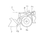
- the “boom operation angle” is an angle ⁇ formed between a line connecting the boom pin P ⁇ b> 1 and the bucket pin P ⁇ b> 2 and the horizontal direction when the horizontal direction is 0 degree in a side view. is there.
- the angle below the horizontal direction is a negative value, and the angle above the horizontal direction is a positive value. Accordingly, the boom operation angle is defined to increase upward.
- the wheel loader according to the third aspect of the present invention is the wheel loader according to the second aspect, wherein the engine control unit is configured such that the forward / reverse switching operation member is in the neutral position and the boom is operated, When the angle indicating that the bottom plate of the bucket has left the ground is reached, the maximum engine speed is limited to a predetermined engine speed.
- the vehicle body when the bottom plate of the bucket is in contact with the ground, the vehicle body is stable and vibration of the vehicle body is suppressed.
- the work implement protrudes forward, and thus vibration is likely to occur.
- the wheel loader since the wheel loader is a traveling wheel type vehicle, it easily swings back and forth around the front wheel.
- the operation angle of the boom is detected, and the engine speed is controlled by detecting that the bucket is separated from the ground. Thereby, the discomfort given to an operator more effectively can be controlled.
- the wheel loader further includes vehicle speed detecting means for detecting the vehicle speed in any one of the first to third wheel loaders.
- the engine control unit limits the maximum engine speed to a predetermined engine speed when the vehicle speed is equal to or lower than a predetermined value.
- the maximum engine speed is limited only when the forward / reverse switching operation member is in the neutral position and the vehicle speed is a predetermined value or less. For this reason, the fall of work efficiency can be suppressed more.
- the wheel loader according to the fifth aspect of the present invention is the wheel loader according to any one of the first to fourth aspects, further comprising a mode switching control unit.
- the mode switching control unit switches the engine output mode between a power mode in which the engine is used at the first horsepower and an economy mode in which the engine is used at the second horsepower lower than the first horsepower.
- the engine control unit limits the maximum engine speed to a predetermined engine speed when the engine output mode is switched to the power mode.
- Some wheel loaders have an engine output mode that includes a power mode that emphasizes workability and an economy mode that emphasizes fuel efficiency.
- the maximum engine speed is set to a relatively high engine speed, and vibration caused by engine rotation is large.
- the economy mode the maximum engine speed is limited, and vibration caused by engine rotation is relatively small. Therefore, in the economy mode, unpleasant vibration caused by engine rotation is small, and there is no need to further limit the maximum engine speed. Further, when the maximum engine speed is further limited in the economy mode, workability may be significantly reduced.
- the wheel loader on the fifth side limits the maximum engine speed only when the engine output mode is the power mode. For this reason, the discomfort given to the operator can be suppressed, and the workability can be prevented from being significantly reduced.
- a wheel loader is the wheel loader according to any one of the first to fifth aspects, wherein the bucket operating member that operates the bucket and the fourth sensor that detects that the bucket operating member is operated. Is further provided.
- the engine control unit limits the maximum engine speed to a predetermined engine speed when the bucket operating member is not operated.
- the wheel loader it is detected that the bucket is operated by the operator, and in this case, the maximum engine speed is not limited. That is, it is detected that the bucket operation is not performed and the maximum engine speed is limited. For this reason, the efficiency of the removal work of earth and sand adhering to a bucket does not fall.
- a wheel loader engine control method is a method for controlling a wheel loader engine including a vehicle body frame, an engine mounted on the vehicle body frame, a work implement, a cab, and an engine control unit.
- the work machine has a boom and a bucket provided at the front end of the boom, and is disposed in front of the body frame.
- the cab includes an operator seat, a boom operation member for operating the boom, and an operation member for switching between forward and backward movement.
- the engine control unit controls the engine speed by the following method.
- the signal indicating that the forward / reverse switching operation member is in the neutral position and the signal indicating that the boom operation member is being operated are received, and the maximum engine speed is limited to a predetermined engine speed.
- the signal indicating that the boom operation member is operated is a signal indicating the operation angle of the boom.
- the side view of the wheel loader concerning one embodiment of the present invention.
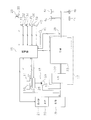
- the schematic block diagram which shows the structure of a wheel loader.
- the flowchart for engine control The figure for demonstrating the operation angle of a boom.
- FIG. 1 is an external view of a wheel loader 1 as a work vehicle
- FIG. 2 is a schematic block diagram of the wheel loader 1.
- the wheel loader 1 includes a body frame 2, a work machine 3, a front wheel 4 a, a rear wheel 4 b, and a cab 5.
- the wheel loader 1 can be self-propelled by rotationally driving the front wheels 4 a and the rear wheels 4 b, and can perform a desired work using the work machine 3.
- the body frame 2 has a front body part 2a and a rear body part 2b.
- the front vehicle body portion 2a and the rear vehicle body portion 2b are connected to each other so as to be swingable in the left-right direction.
- the front vehicle body 2a is provided with a work machine 3 and a front wheel 4a.
- the rear vehicle body 2b is provided with a cab 5 and a rear wheel 4b.
- the work machine 3 is disposed in front of the front vehicle body 2a and includes a boom 6, a bucket 7, a bell crank 8, and the like.
- the boom 6 is swung up and down by a pair of lift cylinders 10.
- the bucket 7 is attached to the tip of the boom 6 and is swung up and down by the bucket cylinder 11 via the bell crank 8.
- the wheel loader 1 includes an engine 15, a power take-out unit 16, a power transmission mechanism 17, a cylinder drive unit 18, and a control unit 19.
- the engine 15 is mounted on the rear vehicle body 4b, and its output is controlled by adjusting the amount of fuel injected into the cylinder.
- the adjustment of the fuel amount is performed by the control unit 19 controlling an electronic governor 21 attached to the fuel injection pump 20 of the engine 15.
- the power take-out unit 16 is a device that distributes the output of the engine 15 to the power transmission mechanism 17 and the cylinder drive unit 18.
- the power transmission mechanism 17 is a mechanism that transmits the driving force from the engine 15 to the front wheels 4a and the rear wheels 4b.
- the power transmission mechanism 17 includes a torque converter 22 and a transmission 23.
- the transmission 23 includes a forward / reverse clutch and a plurality of speed stage clutches corresponding to a plurality of speed stages.
- the transmission 23 is provided with four speed stage clutches, and the speed stage can be switched to four stages from the first speed to the fourth speed.
- the cylinder drive unit 18 has a hydraulic pump 25 and a control valve 26.
- the output of the engine 15 is transmitted to the hydraulic pump 25 via the power take-out unit 16. Further, the hydraulic oil discharged from the hydraulic pump 25 is supplied to the lift cylinder 10 and the bucket cylinder 11 via the control valve 26.
- the control part 19 is comprised with the microcomputer, and mainly receives the signal from the following sensors.
- An accelerator opening sensor 29 that detects the opening of the accelerator pedal 28.
- a boom operation detection sensor 32 that detects that a boom operation lever 31 for operating the boom 6 has been operated.
- a position sensor 34 that detects the position of the forward / reverse switching lever 33.
- An output mode detection sensor 36 that detects the switching position of the selector switch 35 for switching the output mode of the engine.
- a bucket operation detection sensor 40 that detects that a bucket operation member 39 for operating the bucket 7 has been operated.
- a boom operation angle detection sensor 41 for detecting the operation angle of the boom 6.
- the “boom operating angle” refers to a line between the horizontal direction and the line connecting the boom pin P1 and the bucket pin P2 with the horizontal direction set to 0 degree in the side view as shown in FIG. It is an angle ⁇ between them.
- control unit 19 executes control of the rotational speed of the engine 15 and control for limiting the maximum rotational speed based on the signals from the above-described sensors, drive control of the work machine drive unit 18, and control of the transmission 23. Shift control and the like are executed.
- the engine output mode changeover switch 35 is a switch for switching and controlling the output mode of the engine 15 between the power mode and the economy mode by the operation of the operator.
- the power mode is a mode selected when a large engine output is required during running or working.
- the economy mode is a mode that is selected when the engine output is kept low to reduce fuel consumption. Such control of the output mode of the engine 15 is performed by controlling the upper limit value of the fuel injection amount to the engine 15.
- the control process here suppresses vibration that increases as the engine speed increases in a situation where the operator can easily feel vibration due to engine rotation, by limiting the maximum engine speed. By this control process, the operator's discomfort can be suppressed and the comfort can be improved.
- the engine speed is set to the maximum number of rotations in a state in which soil or the like is loaded into the bucket 7 and stopped and waiting for the dump truck. It is possible to raise the situation.
- the wheel loader since the working machine protrudes forward and is a traveling wheel type vehicle, vibration is likely to occur when the bottom plate 7a of the bucket 7 moves away from the ground.
- FIG. 3 shows a flowchart of processing for detecting the above situation and limiting the maximum engine speed.
- step S1 it is determined whether or not the power mode is selected as the engine output mode.
- the power mode is not selected, that is, when the economy mode is selected, the maximum engine speed is limited to 2000 rpm or less, for example.
- the process proceeds from step S1 to step S2, and the engine control process is not executed. That is, as the maximum engine speed, the maximum engine speed set for the economy mode is used.
- the maximum engine speed is set to, for example, 2000 rpm or higher, and vibration due to engine rotation increases. Therefore, in such a case, the process proceeds from step S1 to step S3.
- step S3 it is determined whether the forward / reverse switching lever 33 has been operated to the neutral position.
- the forward / reverse switching lever 33 is in a position other than the neutral position, it is traveling and engine power is required, so it is not preferable to limit the maximum engine speed. Therefore, when the forward / reverse switching lever 33 is not in the neutral position, the process proceeds from step S3 to step S2, and the engine control process is terminated. Therefore, the maximum engine speed set for the power mode is used as the engine maximum engine speed.
- step S4 it is determined whether or not the bucket 7 is not operated. As described above, when removing earth and sand adhered to the bucket 7, an operation of stopping the vehicle and rotating the bucket 7 up and down in a short cycle is performed. In this case, the engine power is required, and it is not preferable to limit the maximum engine speed. Therefore, in such a case, the process proceeds from step S4 to step S2, and the engine control process is not executed. In this case, as described above, the maximum engine speed set for the power mode is used as the engine maximum engine speed.
- step S5 it is determined whether or not the boom 6 has been operated.
- the engine speed is not set to the maximum speed, and in this case, vibration caused by the engine speed is small. Therefore, the process proceeds from step S5 to step S2, and the engine control process is not executed.
- step S6 it is determined whether or not the operation angle ⁇ of the boom 6 is equal to or greater than a threshold value ⁇ a at which vibration is likely to occur.
- the threshold value ⁇ a of the boom operation angle is set to “ ⁇ 30 °”, for example. This threshold value ⁇ a is set as follows.
- the operation angle of the boom 6 is ⁇ 40 ° to ⁇ 45 °. Therefore, as the threshold value ⁇ a, an angle is set in a state where the bottom plate 7a of the bucket 7 is reliably separated from the ground and is raised 5 to 10 ° from the state where the bucket 7 is in contact with the ground. Therefore, the threshold value ⁇ a is set to “ ⁇ 30 °” as an example.
- step S6 When the operation angle of the boom 6 is ⁇ 30 ° or less, it is considered that the bottom plate 7a of the bucket 7 is not separated from the ground, and in this case, vibration caused by engine rotation is small. Therefore, the process proceeds from step S6 to step S2, and the engine control process is not executed.
- step S6 When loading earth and sand in the bucket 7 onto the dump truck, the boom 6 is operated. In this case, in order to perform work efficiently, the operator often sets the engine to the maximum rotation speed. Further, the bottom plate 7a of the bucket 7 is separated from the ground. In such a case, vibration due to engine rotation increases. Therefore, when the boom 6 is operated and the operation angle ⁇ becomes equal to or larger than ⁇ a, the process proceeds from step S6 to step S7.
- step S7 it is determined whether or not the vehicle speed is 4 km / h or less, for example.
- the forward / reverse switching lever may be set to the neutral position during travel and the work may be performed while traveling with inertia.
- the engine power is required to drive the work machine, and it is not preferable to limit the maximum engine speed. Therefore, when the vehicle speed exceeds 4 km / h, the process proceeds from step S7 to step S2, and the engine control process is not executed.
- the maximum engine speed set for the power mode is used as the engine maximum engine speed.
- step S8 control is performed so that the maximum engine speed is 2000 rpm.
- the maximum engine speed is limited when all of the following conditions are satisfied.
- -The power mode is selected as the engine output mode.
- -The forward / reverse switching lever 33 is in the neutral position.
- -Bucket 7 is not being operated.
- the boom 6 is operated and the bottom plate 7a of the bucket 7 is separated from the ground.
- ⁇ The vehicle speed is 4km / h or less.
- vibration due to engine rotation can be suppressed, and uncomfortable feeling given to the operator can be suppressed.
- one of the conditions for limiting the maximum engine speed is whether or not the boom operating angle is equal to or greater than the threshold value ⁇ a (step S6 in FIG. 3). Good. That is, when the boom is operated, the maximum engine speed may be limited regardless of the operation angle.
- the output shaft rotational speed sensor is provided as a sensor for detecting the vehicle speed, but means for detecting the vehicle speed is not limited to this.
- the vehicle speed may be obtained by detecting the input shaft speed and the gear position of the transmission.
- the wheel loader of the present invention can suppress unpleasant vibrations given to the operator by suppressing vibrations caused by engine rotation without impairing workability by simple engine control.
Landscapes
- Engineering & Computer Science (AREA)
- General Engineering & Computer Science (AREA)
- Mechanical Engineering (AREA)
- Chemical & Material Sciences (AREA)
- Combustion & Propulsion (AREA)
- Civil Engineering (AREA)
- Mining & Mineral Resources (AREA)
- Structural Engineering (AREA)
- Operation Control Of Excavators (AREA)
- Control Of Vehicle Engines Or Engines For Specific Uses (AREA)
- Combined Controls Of Internal Combustion Engines (AREA)
- Component Parts Of Construction Machinery (AREA)
- Electrical Control Of Air Or Fuel Supplied To Internal-Combustion Engine (AREA)
Description
本発明は、ホイールローダ及びホイールローダの制御方法に関する。
ホイールローダにおいては、一般的に、燃料コントロールレバーを最高回転位置にセットした状態で操作レバー等が操作され、掘削等の作業が行われる。このような作業状態では、走行時の振動や掘削等の作業に伴う不可避な振動が発生しているので、エンジン回転に起因する振動は相対的に小さくなる。したがって、エンジン回転に起因する振動が、オペレータに不快感を与えることはない。
一方で、例えば土砂等を掘削した後、ブームを操作してダンプトラック等に土砂等を積み込む場合は、走行を停止した状態で、かつエンジン回転数を最高回転数にセットして作業を行う場合が多い。このために、エンジン回転に起因する振動が大きくなり、またこのような状況におけるエンジン回転による振動は、外部からの要因がないこともあって、オペレータに不快感を与えることになる。
ここで、建設機械における振動を抑えるために、特許文献1に示されたようなエンジン制御装置が提案されている。この装置では、作業が操作されていないときに、エンジン回転数が、まず最大共振点の回転数より高い第1の低速回転数に設定される。その後、所定時間経過後に、第1の低速回転数よりさらに低い反共振点の回転数の近傍に位置する第2の低速回転数に、エンジン回転数が設定される。このようにローアイドル回転数を制御することによって、エンジンの共振を避け、低燃費及び低騒音を実現している。
また、特許文献2に示された制御装置では、エンジンの回転数が予め設定された特定回転数域内に入っていると判定された場合は、エンジンの回転数が、特定回転数域よりも高い回転数又は低い回転数に自動的に変更されるようになっている。これにより、騒音や振動の大きい特定回転数域でエンジンが運転されるのを防止し、車両の居住性や耐久性を向上させている。
特許文献1の装置では、エンジンの回転数を最大共振点の回転数より低い回転数に制御し、振動を抑制するようにしている。しかし、ホイールローダにおいては、車体前部にブーム及びバケット等の重量物が装着されており、これらの作動状態によって最大共振点の回転数が変化する。また、前後の車輪に作用する負荷の状況によっても最大共振点の回転数が変化する。したがって、エンジンの回転数が最大共振点の回転数より常に低くなるように制御することは困難である。
また、特許文献2の装置では、エンジンの回転数を特定回転数域外の回転数に自動的に変更するようにしているが、前述の理由と同様の理由により、車両や作業機の状況によって特定回転数域が変化する。したがって、特許文献2の装置においても、常に特定回転数域を避けるようにエンジン回転数を制御することは困難である。
なお、エンジンの最高回転数を制限することによってエンジン回転に起因する振動を抑えることは可能であるが、単純にエンジンの最高回転数を制限した場合、ポンプの吐出量が減り、作業機の動きが遅くなったり、潤滑油不足になったりするという問題がある。
本発明の課題は、簡単なエンジン制御によって、作業性を損なうことなく、エンジン回転に起因する振動を抑えてオペレータに与える不快な振動を抑えることにある。
本発明の第1側面に係るホイールローダは、車体フレームと、車体フレームに搭載されたエンジンと、作業機と、キャブと、第1センサと、第2センサと、エンジン制御部と、を備えている。作業機は、ブーム及びブームの前端に設けられたバケットを有し、車体フレームの前方に配置されている。キャブは、オペレータシート、ブームを操作するブーム操作部材、及び前後進切替用の操作部材が内部に配置されている。第1センサは前後進切替用操作部材がニュートラル位置であることを検知する。第2センサはブームが操作されたことを検知する。エンジン制御部は、前後進切替用操作部材がニュートラル位置であって、かつブーム操作部材が操作されている場合に、エンジンの最高回転数を所定の回転数に制限する。
ここで、前述のように、走行時や掘削等の作業時においては、エンジンの回転に起因する振動以外の振動の方が大きく、エンジンの回転による振動がオペレータに不快感を与えることはない。しかし、例えば、ブームを操作してダンプトラック等に土砂等を積み込む場合には、外部からの振動原因がないこともあって、エンジン回転による振動はオペレータに不快感を与えることになる。
そこでこの装置では、エンジン回転による振動をオペレータが不快に感じるであろう状況を検知し、このような状況においてはエンジン回転数を制御するようにしている。具体的には、第1センサによって前後進切替用操作部材がニュートラル位置であることが検知され、また、第2センサによってブームが操作されたことが検知される。すなわち、車両が停止した状態、あるいは惰性で低速走行しているような状態で作業機が操作されたことを検知し、このような状況では、エンジンの最高回転数が所定の回転数に制限される。
ここでは、オペレータがエンジン回転による振動を不快であると感じる状況になったときに、エンジンの最高回転数が制限される。このため、単純にエンジン回転数を抑える場合に比較して、作業効率の低下を抑えて、オペレータに与える不快感を抑制することができる。
本発明の第2側面に係るホイールローダは、第1側面のホイールローダにおいて、ブームの操作角度を検出する第3センサをさらに備えている。そして、エンジン制御部は、前後進切替用操作部材がニュートラル位置であって、かつブーム操作部材が操作されており、さらにブームの操作角度に応じてエンジンの最高回転数を所定の回転数に制限する。
なお、「ブーム操作角度」とは、図4に示すように、側面視において、水平方向を0度として、ブームピンP1とバケットピンP2とを結ぶ線と、水平方向との間のなす角θである。水平方向よりも下方の角度は、マイナスの値であり、水平方向よりも上方の角度は、プラスの値であるものとする。したがって、ブーム操作角度は、上方に向かって増大するように定義される。
ここでは、ブームの操作角度を検知してエンジン回転数を制御することによって、より効果的に不快な振動を抑えることができる。
本発明の第3側面に係るホイールローダは、第2側面のホイールローダにおいて、エンジン制御部は、前後進切替用操作部材がニュートラル位置であって、かつブームが操作されて、ブームの操作角度が、バケットの底板が地面から離れたことを示す角度になった場合に、エンジンの最高回転数を所定の回転数に制限する。
ここで、バケットの底板が地面に接している状態では、車体は安定しており、車体の振動は抑えられる。しかし、バケットが地面から離れると、作業機が前方に突出していることから、振動が生じやすい。特にホイールローダは走行輪タイプの車両であるために、前輪を中心として前後に振れやすい。
そこで、この第3側面のホイールローダでは、ブームの操作角度を検知し、バケットが地面から離れたことを検知してエンジン回転数を制御するようにしている。これにより、より効果的にオペレータに与える不快感を抑制することができる。
本発明の第4側面に係るホイールローダは、第1から第3側面のいずれかのホイールローダにおいて、車速を検出する車速検出手段をさらに備えている。そして、エンジン制御部は、車速が所定値以下である場合にエンジンの最高回転数を所定の回転数に制限する。
作業の形態によっては、走行途中で前後進切替用操作部材をニュートラル位置に切り替え、惰性走行をしながら作業を行う場合がある。このような場合にまでエンジンの最高回転数を制限すると、作業効率が低下する。
そこで、第4側面のホイールローダでは、前後進切替用操作部材がニュートラル位置であって、かつ車速が所定値以下の場合にのみエンジンの最高回転数を制限するようにしている。このため、作業効率の低下をより抑えることができる。
本発明の第5側面に係るホイールローダは、第1から第4側面のいずれかのホイールローダにおいて、モード切替制御部をさらに備えている。モード切替制御部は、エンジンを第1馬力で使用するパワーモードと、エンジンを第1馬力より低い第2馬力で使用するエコノミーモードと、の間でエンジンの出力モードを切り替える。そして、エンジン制御部は、エンジンの出力モードがパワーモードに切り替えられているときにエンジンの最高回転数を所定の回転数に制限する。
ホイールローダにおいては、エンジンの出力モードとして、作業性を重視したパワーモードと、燃費を重視したエコノミーモードと、を有するものがある。パワーモードにおいては、エンジンの最高回転数が比較的高い回転数に設定され、エンジン回転に起因する振動は大きい。しかし、エコノミーモードにおいては、エンジンの最高回転数は制限され、エンジン回転に起因する振動は比較的小さい。したがって、エコノミーモードでは、エンジン回転に起因する不快な振動は小さく、エンジンの最高回転数をさらに制限する必要はない。また、エコノミーモードにおいてエンジンの最高回転数をさらに制限すると、作業性が著しく低下する場合がある。
そこで、第5側面のホイールローダでは、エンジンの出力モードがパワーモードのときにのみエンジンの最高回転数を制限するようにしている。このため、オペレータに与える不快感を抑制し、しかも作業性が著しく低下するのを抑えることができる。
本発明の第6側面に係るホイールローダは、第1から第5側面のいずれかのホイールローダにおいて、バケットを操作するバケット操作部材と、バケット操作部材が操作されていることを検知する第4センサをさらに備えている。そして、エンジン制御部は、バケット操作部材が操作されていない場合にエンジンの最高回転数を所定の回転数に制限する。
ホイールローダでは、バケットに付着した土砂等を取り除くために、バケットを上下に短い周期で複数回回動させる作業を行う場合がある。このような作業を行う場合は、バケットを駆動するために比較的大きなエンジン出力が必要になる。
そこで、第5側面に係るホイールローダでは、オペレータによってバケットが操作されたことを検知し、この場合にはエンジンの最高回転数を制限しないようにしている。すなわち、バケット操作がされていないことを検知してエンジンの最高回転数を制限するようにしている。このため、バケットに付着した土砂等の除去作業の効率が低下することはない。
本発明に係るホイールローダのエンジン制御方法は、車体フレームと、車体フレームに搭載されたエンジンと、作業機と、キャブと、エンジン制御部と、を備えたホイールローダのエンジンを制御する方法である。作業機は、ブーム及びブームの前端に設けられたバケットを有し、車体フレームの前方に配置されている。キャブは、オペレータシート、ブームを操作するブーム操作部材、及び前後進切替用の操作部材が内部に配置されている。エンジン制御部は以下の方法によってエンジンの回転数を制御する。
前後進切替用操作部材がニュートラル位置であることを示す信号と、ブーム操作部材が操作されていることを示す信号とを受け、エンジンの最高回転数を所定の回転数に制限する。
本発明の別の側面に係るホイールローダのエンジン制御方法では、ブーム操作部材が操作されていることを示す信号は、ブームの操作角度を示す信号である。
以上のような本発明では、簡単なエンジン制御によって、作業性を損なうことなく、エンジン回転に起因する振動を抑えてオペレータに与える不快な振動を抑えることができる。
[構成]
図1は作業車両としてのホイールローダ1の外観図であり、図2はホイールローダ1の概略のブロック構成図である。ホイールローダ1は、車体フレーム2、作業機3、前輪4a、後輪4b、キャブ5を備えている。このホイールローダ1は、前輪4a、後輪4bが回転駆動されることにより自走可能であり、作業機3を用いて所望の作業を行うことができる。
図1は作業車両としてのホイールローダ1の外観図であり、図2はホイールローダ1の概略のブロック構成図である。ホイールローダ1は、車体フレーム2、作業機3、前輪4a、後輪4b、キャブ5を備えている。このホイールローダ1は、前輪4a、後輪4bが回転駆動されることにより自走可能であり、作業機3を用いて所望の作業を行うことができる。
車体フレーム2は前車体部2a及び後車体部2bを有している。前車体部2aと後車体部2bとは互いに左右方向に揺動可能に連結されている。前車体部2aには、作業機3及び前輪4aが設けられている。後車体部2bには、キャブ5及び後輪4bが設けられている。作業機3は、前車体部2aの前方に配置されており、ブーム6、バケット7、ベルクランク8等を有している。ブーム6は1対のリフトシリンダ10によって上下に揺動される。また、バケット7は、ブーム6の先端に装着されており、ベルクランク8を介してバケットシリンダ11によって上下に揺動される。
また、図2に示すように、このホイールローダ1は、エンジン15、動力取り出し部16、動力伝達機構17、シリンダ駆動部18、制御部19を備えている。
エンジン15は、後車体部4bに搭載されており、シリンダ内に噴射する燃料量を調整することにより出力が制御される。この燃料量の調整は、エンジン15の燃料噴射ポンプ20に付設された電子ガバナ21が制御部19によって制御されることで行われる。
動力取り出し部16は、エンジン15の出力を、動力伝達機構17とシリンダ駆動部18とに振り分ける装置である。
動力伝達機構17は、エンジン15からの駆動力を前輪4a及び後輪4bに伝達する機構である。この動力伝達機構17はトルクコンバータ22及びトランスミッション23を有している。トランスミッション23は、前後進用のクラッチと、複数の速度段に対応した複数の速度段クラッチを有している。例えば、トランスミッション23には4つの速度段クラッチが設けられており、速度段を第1速から第4速までの4段階に切り替えることができる。
シリンダ駆動部18は油圧ポンプ25及び制御弁26を有している。油圧ポンプ25へは動力取り出し部16を介してエンジン15の出力が伝達される。また、油圧ポンプ25から吐出された作動油は制御弁26を介してリフトシリンダ10及びバケットシリンダ11に供給される。
制御部19は、マイクロコンピュータで構成されており、主に、以下のセンサからの信号を受け付ける。
(1)アクセルペダル28の開度を検出するアクセル開度センサ29。
(2)ブーム6を操作するためのブーム操作レバー31が操作されたことを検知するブーム操作検知センサ32。
(3)前後進切替レバー33の位置を検出する位置センサ34。
(4)エンジンの出力モードを切り替えるための切替スイッチ35の切替位置を検出する出力モード検知センサ36。
(5)車速センサとしてのトランスミッション23の出力軸回転数センサ38。
(6)バケット7を操作するためのバケット操作部材39が操作されたことを検知するバケット操作検知センサ40。
(7)ブーム6の操作角度を検出するためのブーム操作角度検出センサ41。
(1)アクセルペダル28の開度を検出するアクセル開度センサ29。
(2)ブーム6を操作するためのブーム操作レバー31が操作されたことを検知するブーム操作検知センサ32。
(3)前後進切替レバー33の位置を検出する位置センサ34。
(4)エンジンの出力モードを切り替えるための切替スイッチ35の切替位置を検出する出力モード検知センサ36。
(5)車速センサとしてのトランスミッション23の出力軸回転数センサ38。
(6)バケット7を操作するためのバケット操作部材39が操作されたことを検知するバケット操作検知センサ40。
(7)ブーム6の操作角度を検出するためのブーム操作角度検出センサ41。
なお、「ブームの操作角度」とは、前述のように、図4に示すように、側面視において、水平方向を0度として、ブームピンP1とバケットピンP2とを結ぶ線と、水平方向との間のなす角θである。
そして、制御部19は、以上の各センサからの信号に基づいて、エンジン15の回転数の制御及び最高回転数を制限する制御を実行するとともに、作業機駆動部18の駆動制御、トランスミッション23の変速制御等を実行する。
なお、エンジンの出力モード切替スイッチ35は、オペレータの操作によって、エンジン15の出力モードをパワーモードとエコノミーモードとで切替制御するためのスイッチである。パワーモードは、走行あるいは作業時において大きなエンジン出力を必要とする際に選択されるモードである。また、エコノミーモードは低燃費化のためにエンジン出力を低く抑える際に選択されるモードである。このようなエンジン15の出力モードの制御は、エンジン15への燃料噴射量の上限値を制御することにより行われる。
[エンジンの最高回転数の制御]
ここでの制御処理は、オペレータがエンジン回転による振動を感じやすい状況で、エンジン回転数の上昇に伴って増大する振動を、エンジンの最高回転数を制限することで抑制するものである。この制御処理によって、オペレータの不快感を抑えて快適性を向上することができる。
ここでの制御処理は、オペレータがエンジン回転による振動を感じやすい状況で、エンジン回転数の上昇に伴って増大する振動を、エンジンの最高回転数を制限することで抑制するものである。この制御処理によって、オペレータの不快感を抑えて快適性を向上することができる。
オペレータがエンジン回転による振動を不快に感じる具体例としては、バケット7に土砂等を積み込み、停止してダンプトラックを待っているような状態で、エンジン回転数を最高回転数にセットし、ブーム6を上昇させるような状況が考えられる。特に、ホイールローダでは、作業機が前方に突出し、かつ走行輪タイプの車両であるために、バケット7の底板7aが地面から離れると振動が生じやすい。
以上のような状況を検知し、エンジンの最高回転数を制限する処理のフローチャートを図3に示している。
図3において、ステップS1では、エンジン出力モードとしてパワーモードが選択されているか否かを判断する。パワーモードが選択されていない場合、すなわちエコノミーモードが選択されている場合は、エンジンの最高回転数は例えば2000rpm以下に制限される。このようなエコノミーモードでは、エンジン回転数は2000rpm以上に上がらないために、エンジン回転に起因する振動は比較的小さい。したがって、このような場合は、ステップS1からステップS2に移行し、エンジン制御処理は実行されない。すなわち、エンジンの最高回転数としては、エコノミーモード用として設定された最高回転数が用いられる。
エンジン出力モードとしてパワーモードが選択されている場合は、エンジンの最高回転数は例えば2000rpm以上の回転数に設定されているので、エンジン回転に起因する振動は大きくなる。したがって、このような場合はステップS1からステップS3に移行する。
ステップS3では、前後進切替レバー33がニュートラル位置に操作されているか否かを判断する。前後進切替レバー33がニュートラル位置以外の場合は、走行中であってエンジンのパワーが要求されるので、エンジンの最高回転数を制限することは好ましくない。そこで、前後進切替レバー33がニュートラル位置以外の場合は、ステップS3からステップS2に移行し、このエンジン制御処理を終了する。したがって、エンジンの最高回転数としては、パワーモード用として設定された最高回転数が用いられる。
前後進切替レバー33がニュートラル位置の場合は、停止あるいは惰性による低速走行であるので、ステップS3からステップS4に移行する。ステップS4では、バケット7の操作がなされていないか否かを判断する。前述のように、バケット7に付着した土砂等を除去する場合、車両を停止させてバケット7を短い周期で上下に回動させる操作が行われる。この場合は、エンジンのパワーが必要であって、エンジンの最高回転数を制限することは好ましくない。したがって、このような場合は、ステップS4からステップS2に移行し、エンジン制御処理は実行されない。この場合は、前記同様に、エンジンの最高回転数としては、パワーモード用として設定された最高回転数が用いられる。
バケット7の操作がなされていない場合は、ステップS4からステップS5に移行する。ステップS5では、ブーム6の操作がなされた否かを判断する。ブーム6の操作がなされていない場合は、エンジン回転数は最高回転数に設定されないので、この場合はエンジン回転に起因する振動は小さい。したがって、ステップS5からステップS2に移行し、エンジン制御処理は実行されない。
また、ステップS6では、ブーム6の操作角度θが、振動が生じやすいしきい値θa以上であるか否かを判断する。ここで、ブーム操作角度のしきい値θaとしては、例えば「-30°」に設定されている。このしきい値θaは以下のようにして設定される。
すなわち、バケット7の底板7aが地面に接するようにブーム6を下げた場合、ブーム6の操作角度は-40°~-45°になる。そこで、しきい値θaとしては、バケット7の底板7aが地面から確実に離れた状態として、バケット7が地面に接している状態から5~10°上昇した状態の角度が設定される。したがって、しきい値θaは、一例として、「-30°」に設定される。
ブーム6の操作角度が-30°以下である場合は、バケット7の底板7aが地面から離れていないとみなし、この場合はエンジン回転に起因する振動は小さい。したがって、ステップS6からステップS2に移行し、エンジン制御処理は実行されない。
バケット7内の土砂等をダンプトラックに積み込む場合は、ブーム6が操作される。この場合は、効率的に作業を行うために、オペレータはエンジンを最高回転数にセットする場合が多い。また、バケット7の底板7aが地面から離れる。このような場合は、エンジン回転による振動は大きくなる。そこで、ブーム6が操作されて操作角度θがθa以上になった場合は、ステップS6からステップS7に移行する。
ステップS7では、車速が例えば4km/h以下であるか否かを判断する。作業の形態によっては、走行中に前後進切替レバーをニュートラル位置にして、惰性で走行しながら作業を行う場合がある。このような場合は、作業機を駆動するためにエンジンのパワーが必要であり、エンジンの最高回転数を制限することは好ましくない。そこで、車速が4km/hを越えているような場合は、ステップS7からステップS2に移行し、エンジン制御処理は実行されない。この場合は、前記同様に、エンジンの最高回転数としては、パワーモード用として設定された最高回転数が用いられる。
車速が例えば4km/h以下の場合は、車両は停止しているか、あるいは惰性によって車両が移動しているような状態である。このような場合にエンジンの回転数を予め設定されている最高回転数まで上昇させると、エンジン回転に起因する振動が大きくなる。また、この振動によってオペレータに不快感を与える。そこで、車速が4km/h以下の場合は、ステップS7からステップS8に移行する。このステップS8では、エンジンの最高回転数が2000rpmになるように制御する。
以上のように、この制御処理では、以下のすべての条件が満たされたときに、エンジンの最高回転数が制限される。
・エンジン出力モードとしてパワーモードが選択されている。
・前後進切替レバー33がニュートラル位置である。
・バケット7が操作されていない。
・ブーム6が操作されてバケット7の底板7aが地面から離れている。
・車速が4km/h以下である。
・エンジン出力モードとしてパワーモードが選択されている。
・前後進切替レバー33がニュートラル位置である。
・バケット7が操作されていない。
・ブーム6が操作されてバケット7の底板7aが地面から離れている。
・車速が4km/h以下である。
そして、以上の制御処理によって、エンジン回転による振動が抑えられ、オペレータに与える不快感を抑えることができる。
[特徴]
(1)オペレータに不快感を与えるような状況を検知し、そのような状況ではエンジンの最高回転数を制限するので、複雑な制御が不要になる。しかも、この制御処理によって、車両の仕様等によらずに常に効果的にエンジン回転に起因するオペレータへの不快感を抑えることができる。さらに、作業性を損なわないようにエンジン回転数を制御するので、作業効率の低下を防止できる。
(1)オペレータに不快感を与えるような状況を検知し、そのような状況ではエンジンの最高回転数を制限するので、複雑な制御が不要になる。しかも、この制御処理によって、車両の仕様等によらずに常に効果的にエンジン回転に起因するオペレータへの不快感を抑えることができる。さらに、作業性を損なわないようにエンジン回転数を制御するので、作業効率の低下を防止できる。
(2)惰性で走行しながら作業を行う場合は、エンジンの最高回転数を制限しない。したがって、作業効率の低下をより避けることができる。
(3)エンジンの出力モードがパワーモードのときにのみエンジンの最高回転数を制限するようにしている。このため、不要な制御を行うのを防止できる。また、エコノミーモードにおいて作業性が著しく低下するのを防止できる。
(4)バケット7に付着した土砂等を取り除くための作業を行う場合は、バケット操作が検知されて、エンジンの最高回転数を制限する処理は実行されない。このため、バケット7に付着した土砂等の除去作業の効率が低下することはない。
[他の実施形態]
本発明は以上のような実施形態に限定されるものではなく、本発明の範囲を逸脱することなく種々の変形又は修正が可能である。
本発明は以上のような実施形態に限定されるものではなく、本発明の範囲を逸脱することなく種々の変形又は修正が可能である。
前記実施形態では、エンジンの最高回転数を制限する条件の1つとして、ブームの操作角度がしきい値θa以上か否か(図3のステップS6)を挙げたが、この条件を除いてもよい。すなわち、ブームが操作された場合は、その操作角度にかかわらず、エンジンの最高回転数を制限するようにしてもよい。
前記実施形態では、車速を検出するためのセンサとして出力軸回転数センサを設けたが、車速を検出するための手段はこれに限定されない。例えば、トランスミッションの入力軸回転数と変速段を検知して車速を求めるようにしてもよい。
また、実施形態で挙げた数値は例示のための数値であって、これらの数値に限定されることはない。
本発明のホイールローダでは、簡単なエンジン制御によって、作業性を損なうことなく、エンジン回転に起因する振動を抑えてオペレータに与える不快な振動を抑えることができる。
1 ホイールローダ
3 作業機
6 ブーム
7 バケット
7a バケットの底板
15 エンジン
19 制御部
31 ブーム操作レバー
32 ブーム操作検知センサ(第2センサ)
33 前後進切替レバー
34 位置センサ(第1センサ)
35 出力モード切替スイッチ
36 出力モード検知センサ
38 出力軸回転数センサ
39 バケット操作部材
40 バケット操作検知センサ(第4センサ)
41 ブーム操作角度検出センサ(第3センサ)
3 作業機
6 ブーム
7 バケット
7a バケットの底板
15 エンジン
19 制御部
31 ブーム操作レバー
32 ブーム操作検知センサ(第2センサ)
33 前後進切替レバー
34 位置センサ(第1センサ)
35 出力モード切替スイッチ
36 出力モード検知センサ
38 出力軸回転数センサ
39 バケット操作部材
40 バケット操作検知センサ(第4センサ)
41 ブーム操作角度検出センサ(第3センサ)
Claims (8)
- 車体フレームと、
前記車体フレームに搭載されたエンジンと、
ブーム及び前記ブームの前端に設けられたバケットを有し、前記車体フレームの前方に配置された作業機と、
オペレータシート、前記ブームを操作するブーム操作部材、及び前後進切替用の操作部材が内部に配置されたキャブと、
前記前後進切替用操作部材がニュートラル位置であることを検知する第1センサと、
前記ブームが操作されたことを検知する第2センサと、
前記前後進切替用操作部材がニュートラル位置であって、かつ前記ブーム操作部材が操作されている場合に、前記エンジンの最高回転数を所定の回転数に制限するエンジン制御部と、
を備えたホイールローダ。 - 前記ブームの操作角度を検出する第3センサをさらに備え、
前記エンジン制御部は、前記前後進切替用操作部材がニュートラル位置であって、かつ前記ブーム操作部材が操作されており、さらに前記ブームの操作角度に応じて前記エンジンの最高回転数を所定の回転数に制限する、
請求項1に記載のホイールローダ。 - 前記エンジン制御部は、前記前後進切替用操作部材がニュートラル位置であって、かつ前記ブームが操作されて、前記ブームの操作角度が、前記バケットの底板が地面から離れたことを示す角度になった場合に、前記エンジンの最高回転数を所定の回転数に制限する、請求項2に記載のホイールローダ。
- 車速を検出する車速検出手段をさらに備え、
前記エンジン制御部は、車速が所定値以下である場合に前記エンジンの最高回転数を前記所定の回転数に制限する、
請求項1から3のいずれかに記載のホイールローダ。 - 前記エンジンを第1馬力で使用するパワーモードと、前記エンジンを前記第1馬力より低い第2馬力で使用するエコノミーモードと、の間で前記エンジンの出力モードを切り替えるモード切替制御部をさらに備え、
前記エンジン制御部は、前記エンジンの出力モードが前記パワーモードに切り替えられているときに前記エンジンの最高回転数を前記所定の回転数に制限する、請求項1から4のいずれかに記載のホイールローダ。 - 前記バケットを操作するバケット操作部材と、
前記バケット操作部材が操作されていることを検知する第4センサをさらに備え、
前記エンジン制御部は、前記バケット操作部材が操作されていない場合に前記エンジンの最高回転数を前記所定の回転数に制限する、請求項1から5のいずれかに記載のホイールローダ。 - 車体フレームと、
前記車体フレームに搭載されたエンジンと、
ブーム及び前記ブームの前端に設けられたバケットを有し、前記車体フレームの前方に配置された作業機と、
オペレータシート、前記ブームを操作するブーム操作部材、及び前後進切替用の操作部材が内部に配置されたキャブと、
前記エンジンの回転数を制御するエンジン制御部と、
を備えたホイールローダのエンジン制御方法であって、
前記前後進切替用操作部材がニュートラル位置であることを示す信号と、前記ブーム操作部材が操作されていることを示す信号とを受け、前記エンジンの最高回転数を所定の回転数に制限する、
ホイールローダのエンジン制御方法。 - 前記ブーム操作部材が操作されていることを示す信号は、前記ブームの操作角度を示す信号である、請求項7に記載のホイールローダのエンジン制御方法。
Priority Applications (3)
| Application Number | Priority Date | Filing Date | Title |
|---|---|---|---|
| US13/823,362 US8954242B2 (en) | 2012-06-22 | 2012-09-19 | Wheel loader and control method of wheel loader |
| EP12842692.1A EP2700799B1 (en) | 2012-06-22 | 2012-09-19 | Wheel loader |
| CN201280003634.1A CN103608570B (zh) | 2012-06-22 | 2012-09-19 | 轮式装载机及轮式装载机的控制方法 |
Applications Claiming Priority (2)
| Application Number | Priority Date | Filing Date | Title |
|---|---|---|---|
| JP2012140515A JP5161386B1 (ja) | 2012-06-22 | 2012-06-22 | ホイールローダ及びホイールローダの制御方法 |
| JP2012-140515 | 2012-06-22 |
Publications (1)
| Publication Number | Publication Date |
|---|---|
| WO2013190715A1 true WO2013190715A1 (ja) | 2013-12-27 |
Family
ID=48013597
Family Applications (1)
| Application Number | Title | Priority Date | Filing Date |
|---|---|---|---|
| PCT/JP2012/073868 Ceased WO2013190715A1 (ja) | 2012-06-22 | 2012-09-19 | ホイールローダ及びホイールローダの制御方法 |
Country Status (5)
| Country | Link |
|---|---|
| US (1) | US8954242B2 (ja) |
| EP (1) | EP2700799B1 (ja) |
| JP (1) | JP5161386B1 (ja) |
| CN (1) | CN103608570B (ja) |
| WO (1) | WO2013190715A1 (ja) |
Families Citing this family (8)
| Publication number | Priority date | Publication date | Assignee | Title |
|---|---|---|---|---|
| US10059341B2 (en) | 2016-06-17 | 2018-08-28 | Caterpillar Inc. | Control strategy for reduced fuel consumption in machine and powertrain system with same |
| DE102017203835A1 (de) * | 2017-03-08 | 2018-09-13 | Zf Friedrichshafen Ag | Verfahren zum Ermitteln einer Soll-Drehzahl einer Antriebsmaschine einer Arbeitsmaschine mit einem Stufenlosgetriebe und mit einer Arbeitshydraulik |
| US10370826B2 (en) | 2017-03-08 | 2019-08-06 | Cnh Industrial America Llc | System and method for reducing fuel consumption of a work vehicle |
| DE102017106629A1 (de) * | 2017-03-28 | 2018-10-04 | Ghh Fahrzeuge Gmbh | Verfahren zum Betrieb eines selbstfahrenden Untertagefahrzeugs |
| JP7038515B2 (ja) * | 2017-09-29 | 2022-03-18 | 日立建機株式会社 | ホイールローダ |
| CN109853660B (zh) * | 2018-12-29 | 2021-05-07 | 山东欧泰隆重工有限公司 | 一种装载机智能操控系统 |
| FR3096698B1 (fr) * | 2019-06-03 | 2021-04-30 | Manitou Bf | Engin de manutention de charge |
| US20230055510A1 (en) * | 2021-08-18 | 2023-02-23 | Schwarze Industries, Inc. | System and method for providing a transient power assist feature in a motor vehicle |
Citations (7)
| Publication number | Priority date | Publication date | Assignee | Title |
|---|---|---|---|---|
| JPS63241226A (ja) * | 1987-03-28 | 1988-10-06 | Hitachi Constr Mach Co Ltd | ホイ−ル式油圧シヨベルの油圧制御装置 |
| JP2000136739A (ja) * | 1998-08-25 | 2000-05-16 | Hitachi Constr Mach Co Ltd | 破砕機のエンジン制御装置 |
| JP2005256595A (ja) * | 2004-02-10 | 2005-09-22 | Komatsu Ltd | 建設機械の作業機の制御装置、建設機械の作業機の制御方法、及びこの方法をコンピュータに実行させるプログラム |
| WO2010147232A1 (ja) * | 2009-06-19 | 2010-12-23 | 日立建機株式会社 | 作業車両の原動機制御装置 |
| JP2011157931A (ja) * | 2010-02-03 | 2011-08-18 | Komatsu Ltd | エンジンの制御装置 |
| WO2011145684A1 (ja) * | 2010-05-20 | 2011-11-24 | 株式会社小松製作所 | 建設機械 |
| JP2012052457A (ja) * | 2010-08-31 | 2012-03-15 | Komatsu Ltd | フォークリフトのエンジン制御装置 |
Family Cites Families (24)
| Publication number | Priority date | Publication date | Assignee | Title |
|---|---|---|---|---|
| KR910009257B1 (ko) * | 1985-09-07 | 1991-11-07 | 히다찌 겡끼 가부시기가이샤 | 유압건설기계의 제어시스템 |
| JPS62142834A (ja) * | 1985-12-17 | 1987-06-26 | Komatsu Ltd | クレ−ンのエンジン制御装置 |
| JP2670815B2 (ja) * | 1988-07-29 | 1997-10-29 | 株式会社小松製作所 | 建設機械の制御装置 |
| US5277269A (en) * | 1991-02-05 | 1994-01-11 | Hitachi Construction Machinery Co., Ltd. | Engine revolution speed control device for a hydraulically driven vehicle |
| US5638677A (en) * | 1991-03-29 | 1997-06-17 | Hitachi Construction Machinery Co., Ltd. | Control device for hydraulically propelled work vehicle |
| JPH0932596A (ja) | 1995-07-18 | 1997-02-04 | Hitachi Constr Mach Co Ltd | 原動機制御装置 |
| US5586536A (en) * | 1995-11-29 | 1996-12-24 | Samsung Heavy Industries Co., Ltd. | Apparatus for and method of controlling engine RPM in hydraulic construction equipment |
| US5999872A (en) * | 1996-02-15 | 1999-12-07 | Kabushiki Kaisha Kobe Seiko Sho | Control apparatus for hydraulic excavator |
| JP3419661B2 (ja) * | 1997-10-02 | 2003-06-23 | 日立建機株式会社 | 油圧建設機械の原動機のオートアクセル装置及び原動機と油圧ポンプの制御装置 |
| JP3511453B2 (ja) * | 1997-10-08 | 2004-03-29 | 日立建機株式会社 | 油圧建設機械の原動機と油圧ポンプの制御装置 |
| JP2000248975A (ja) * | 1999-03-01 | 2000-09-12 | Komatsu Ltd | 作業車両のエンジン回転数制御装置 |
| US6234254B1 (en) * | 1999-03-29 | 2001-05-22 | Caterpillar Inc. | Apparatus and method for controlling the efficiency of the work cycle associated with an earthworking machine |
| JP2000303872A (ja) * | 1999-04-22 | 2000-10-31 | Hitachi Constr Mach Co Ltd | 油圧式建設機械のエンジン制御装置 |
| JP3819699B2 (ja) | 2000-10-20 | 2006-09-13 | 日立建機株式会社 | 油圧走行車両 |
| WO2004029435A1 (ja) * | 2002-09-26 | 2004-04-08 | Hitachi Construction Machinery Co., Ltd. | 建設機械の原動機制御装置 |
| KR100824662B1 (ko) * | 2004-04-08 | 2008-04-24 | 가부시키가이샤 고마쓰 세이사쿠쇼 | 작업기계의 유압구동장치 |
| KR20070007174A (ko) * | 2004-05-07 | 2007-01-12 | 가부시키가이샤 고마쓰 세이사쿠쇼 | 작업기계의 유압구동장치 |
| JP4413122B2 (ja) * | 2004-10-13 | 2010-02-10 | 日立建機株式会社 | 油圧建設機械の制御装置 |
| WO2007043290A1 (ja) * | 2005-10-14 | 2007-04-19 | Komatsu Ltd. | 作業車両のエンジンおよび油圧ポンプの制御装置および方法 |
| JP4625751B2 (ja) * | 2005-10-21 | 2011-02-02 | 株式会社小松製作所 | 油圧駆動装置 |
| JP5046690B2 (ja) * | 2007-03-12 | 2012-10-10 | 日立建機株式会社 | 作業車両の制御装置 |
| US8463509B2 (en) * | 2008-03-21 | 2013-06-11 | Komatsu Ltd. | Working vehicle, control device for working vehicle, and control method for working vehicle |
| JP5248387B2 (ja) * | 2009-03-25 | 2013-07-31 | 株式会社小松製作所 | ホイールローダ |
| US8510002B2 (en) * | 2009-10-14 | 2013-08-13 | Komatsu Ltd. | Engine speed control device and motor grader including the same |
-
2012
- 2012-06-22 JP JP2012140515A patent/JP5161386B1/ja active Active
- 2012-09-19 CN CN201280003634.1A patent/CN103608570B/zh active Active
- 2012-09-19 WO PCT/JP2012/073868 patent/WO2013190715A1/ja not_active Ceased
- 2012-09-19 EP EP12842692.1A patent/EP2700799B1/en active Active
- 2012-09-19 US US13/823,362 patent/US8954242B2/en active Active
Patent Citations (7)
| Publication number | Priority date | Publication date | Assignee | Title |
|---|---|---|---|---|
| JPS63241226A (ja) * | 1987-03-28 | 1988-10-06 | Hitachi Constr Mach Co Ltd | ホイ−ル式油圧シヨベルの油圧制御装置 |
| JP2000136739A (ja) * | 1998-08-25 | 2000-05-16 | Hitachi Constr Mach Co Ltd | 破砕機のエンジン制御装置 |
| JP2005256595A (ja) * | 2004-02-10 | 2005-09-22 | Komatsu Ltd | 建設機械の作業機の制御装置、建設機械の作業機の制御方法、及びこの方法をコンピュータに実行させるプログラム |
| WO2010147232A1 (ja) * | 2009-06-19 | 2010-12-23 | 日立建機株式会社 | 作業車両の原動機制御装置 |
| JP2011157931A (ja) * | 2010-02-03 | 2011-08-18 | Komatsu Ltd | エンジンの制御装置 |
| WO2011145684A1 (ja) * | 2010-05-20 | 2011-11-24 | 株式会社小松製作所 | 建設機械 |
| JP2012052457A (ja) * | 2010-08-31 | 2012-03-15 | Komatsu Ltd | フォークリフトのエンジン制御装置 |
Non-Patent Citations (1)
| Title |
|---|
| See also references of EP2700799A4 * |
Also Published As
| Publication number | Publication date |
|---|---|
| US8954242B2 (en) | 2015-02-10 |
| JP2014005618A (ja) | 2014-01-16 |
| EP2700799B1 (en) | 2015-03-04 |
| JP5161386B1 (ja) | 2013-03-13 |
| EP2700799A1 (en) | 2014-02-26 |
| US20140058649A1 (en) | 2014-02-27 |
| CN103608570A (zh) | 2014-02-26 |
| CN103608570B (zh) | 2015-03-11 |
| EP2700799A4 (en) | 2014-03-26 |
Similar Documents
| Publication | Publication Date | Title |
|---|---|---|
| JP5161386B1 (ja) | ホイールローダ及びホイールローダの制御方法 | |
| JP5248387B2 (ja) | ホイールローダ | |
| CN103429875B (zh) | 作业车辆的驱动控制装置 | |
| CN104011302B (zh) | 作业车辆 | |
| JP5503955B2 (ja) | 作業車両の変速制御装置 | |
| US8655557B2 (en) | Motor control device for working vehicle | |
| CN105378348B (zh) | 作业车辆及其控制方法 | |
| JP5996314B2 (ja) | ホイールローダおよびホイールローダのエンジン制御方法 | |
| JP4648407B2 (ja) | 建設車両 | |
| CN102770644B (zh) | 轮式装载机 | |
| JP2010223416A5 (ja) | ||
| WO2013136537A1 (ja) | 作業車両及び作業車両の制御方法 | |
| CN101341321B (zh) | 工程作业车辆的发动机控制装置 | |
| JP2011001845A (ja) | 産業車両のエンジン回転数制御装置 | |
| CN109072954B (zh) | 作业车辆 | |
| JP2010133469A (ja) | 作業車両 | |
| JP5270464B2 (ja) | 産業車両の変速制御装置 | |
| CN113272193A (zh) | 作业机械以及作业机械的控制方法 | |
| JP2011157972A (ja) | 作業車両のエンジン制御装置 | |
| WO2013021692A1 (ja) | バックホーローダ |
Legal Events
| Date | Code | Title | Description |
|---|---|---|---|
| WWE | Wipo information: entry into national phase |
Ref document number: 13823362 Country of ref document: US |
|
| WWE | Wipo information: entry into national phase |
Ref document number: 2012842692 Country of ref document: EP |
|
| 121 | Ep: the epo has been informed by wipo that ep was designated in this application |
Ref document number: 12842692 Country of ref document: EP Kind code of ref document: A1 |
|
| NENP | Non-entry into the national phase |
Ref country code: DE |