WO2013190783A1 - Unité d'actionneur à vibration, appareil à étages, appareil optique et appareil à étages - Google Patents
Unité d'actionneur à vibration, appareil à étages, appareil optique et appareil à étages Download PDFInfo
- Publication number
- WO2013190783A1 WO2013190783A1 PCT/JP2013/003470 JP2013003470W WO2013190783A1 WO 2013190783 A1 WO2013190783 A1 WO 2013190783A1 JP 2013003470 W JP2013003470 W JP 2013003470W WO 2013190783 A1 WO2013190783 A1 WO 2013190783A1
- Authority
- WO
- WIPO (PCT)
- Prior art keywords
- vibration
- actuator unit
- vibration actuator
- electromechanical transducer
- unit
- Prior art date
- Legal status (The legal status is an assumption and is not a legal conclusion. Google has not performed a legal analysis and makes no representation as to the accuracy of the status listed.)
- Ceased
Links
Images






Classifications
-
- H—ELECTRICITY
- H02—GENERATION; CONVERSION OR DISTRIBUTION OF ELECTRIC POWER
- H02N—ELECTRIC MACHINES NOT OTHERWISE PROVIDED FOR
- H02N2/00—Electric machines in general using piezoelectric effect, electrostriction or magnetostriction
- H02N2/10—Electric machines in general using piezoelectric effect, electrostriction or magnetostriction producing rotary motion, e.g. rotary motors
- H02N2/14—Drive circuits; Control arrangements or methods
-
- G—PHYSICS
- G02—OPTICS
- G02B—OPTICAL ELEMENTS, SYSTEMS OR APPARATUS
- G02B7/00—Mountings, adjusting means, or light-tight connections, for optical elements
- G02B7/02—Mountings, adjusting means, or light-tight connections, for optical elements for lenses
- G02B7/04—Mountings, adjusting means, or light-tight connections, for optical elements for lenses with mechanism for focusing or varying magnification
- G02B7/08—Mountings, adjusting means, or light-tight connections, for optical elements for lenses with mechanism for focusing or varying magnification adapted to co-operate with a remote control mechanism
-
- G—PHYSICS
- G02—OPTICS
- G02B—OPTICAL ELEMENTS, SYSTEMS OR APPARATUS
- G02B7/00—Mountings, adjusting means, or light-tight connections, for optical elements
- G02B7/02—Mountings, adjusting means, or light-tight connections, for optical elements for lenses
- G02B7/04—Mountings, adjusting means, or light-tight connections, for optical elements for lenses with mechanism for focusing or varying magnification
- G02B7/10—Mountings, adjusting means, or light-tight connections, for optical elements for lenses with mechanism for focusing or varying magnification by relative axial movement of several lenses, e.g. of varifocal objective lens
-
- H—ELECTRICITY
- H02—GENERATION; CONVERSION OR DISTRIBUTION OF ELECTRIC POWER
- H02N—ELECTRIC MACHINES NOT OTHERWISE PROVIDED FOR
- H02N2/00—Electric machines in general using piezoelectric effect, electrostriction or magnetostriction
- H02N2/0005—Electric machines in general using piezoelectric effect, electrostriction or magnetostriction producing non-specific motion; Details common to machines covered by H02N2/02 - H02N2/16
- H02N2/001—Driving devices, e.g. vibrators
- H02N2/003—Driving devices, e.g. vibrators using longitudinal or radial modes combined with bending modes
- H02N2/004—Rectangular vibrators
-
- H—ELECTRICITY
- H02—GENERATION; CONVERSION OR DISTRIBUTION OF ELECTRIC POWER
- H02N—ELECTRIC MACHINES NOT OTHERWISE PROVIDED FOR
- H02N2/00—Electric machines in general using piezoelectric effect, electrostriction or magnetostriction
- H02N2/0095—Electric machines in general using piezoelectric effect, electrostriction or magnetostriction producing combined linear and rotary motion, e.g. multi-direction positioners
-
- H—ELECTRICITY
- H02—GENERATION; CONVERSION OR DISTRIBUTION OF ELECTRIC POWER
- H02N—ELECTRIC MACHINES NOT OTHERWISE PROVIDED FOR
- H02N2/00—Electric machines in general using piezoelectric effect, electrostriction or magnetostriction
- H02N2/02—Electric machines in general using piezoelectric effect, electrostriction or magnetostriction producing linear motion, e.g. actuators; Linear positioners ; Linear motors
- H02N2/026—Electric machines in general using piezoelectric effect, electrostriction or magnetostriction producing linear motion, e.g. actuators; Linear positioners ; Linear motors by pressing one or more vibrators against the driven body
-
- H—ELECTRICITY
- H02—GENERATION; CONVERSION OR DISTRIBUTION OF ELECTRIC POWER
- H02N—ELECTRIC MACHINES NOT OTHERWISE PROVIDED FOR
- H02N2/00—Electric machines in general using piezoelectric effect, electrostriction or magnetostriction
- H02N2/02—Electric machines in general using piezoelectric effect, electrostriction or magnetostriction producing linear motion, e.g. actuators; Linear positioners ; Linear motors
- H02N2/028—Electric machines in general using piezoelectric effect, electrostriction or magnetostriction producing linear motion, e.g. actuators; Linear positioners ; Linear motors along multiple or arbitrary translation directions, e.g. XYZ stages
-
- H—ELECTRICITY
- H10—SEMICONDUCTOR DEVICES; ELECTRIC SOLID-STATE DEVICES NOT OTHERWISE PROVIDED FOR
- H10N—ELECTRIC SOLID-STATE DEVICES NOT OTHERWISE PROVIDED FOR
- H10N30/00—Piezoelectric or electrostrictive devices
- H10N30/20—Piezoelectric or electrostrictive devices with electrical input and mechanical output, e.g. functioning as actuators or vibrators
- H10N30/202—Piezoelectric or electrostrictive devices with electrical input and mechanical output, e.g. functioning as actuators or vibrators using longitudinal or thickness displacement combined with bending, shear or torsion displacement
- H10N30/2023—Piezoelectric or electrostrictive devices with electrical input and mechanical output, e.g. functioning as actuators or vibrators using longitudinal or thickness displacement combined with bending, shear or torsion displacement having polygonal or rectangular shape
Definitions
- the present invention relates to a vibration actuator unit, a stage device, an optical device, and a stage device.
- Patent Document 1 Japanese Patent Laid-Open No. 11-316607 Patent Document 2 Japanese Patent Laid-Open No. 2011-147266
- the equipment scale is large because actuators are provided for each of the X direction drive and Y direction drive. Adding scale and encoder increases cost and space factor.
- the electromechanical transducer that converts the electrical vibration of the applied drive voltage into mechanical vibration and the mechanical vibration of the electromechanical transducer in contact with the driven surface to be driven.
- the electromechanical conversion element is periodically bent in the first vibration surface intersecting the driven surface and the contact portion is in the first vibration surface.
- a vibration actuator unit that is periodically bent in a second vibration surface intersecting the first vibration surface and vibrates the contact portion in the second vibration surface.
- an optical device including the vibration actuator unit is provided.
- the stage apparatus provided with the said vibration actuator unit is provided.
- the electromechanical transducer that converts the supplied drive power into mechanical vibration
- the contact portion that transmits the mechanical vibration from the electromechanical transducer and drives the driven object
- the contact A biasing force generating unit that generates a biasing force that biases the unit toward the driving target, and a relative relationship between the driving target and the electromechanical conversion element based on a change in physical quantity that is the biasing force generated by the biasing force generating unit.
- a vibration actuator unit is provided that includes a position detection unit that detects a position.
- an optical device including the vibration actuator unit is provided. Moreover, according to the 6th aspect of this invention, the stage apparatus provided with the said vibration actuator unit is provided.
- FIG. 2 is a schematic cross-sectional view of the stage device 101.
- FIG. 3 is a schematic exploded perspective view of a vibration actuator unit 201.
- FIG. 3 is a schematic side view of a vibration actuator unit 201.
- FIG. 4 is a diagram showing a drive signal waveform of a vibration actuator unit 201.
- 3 is a schematic side view of a vibration actuator unit 201.
- FIG. 4 is a schematic diagram showing the structure of a vibration actuator unit 201.
- FIG. FIG. 4 is a diagram showing a drive signal waveform of a vibration actuator unit 201.
- 3 is a schematic side view of a vibration actuator unit 201.
- FIG. 2 is a schematic cross-sectional view of a stage device 102.
- FIG. 1 is a schematic cross-sectional view of a stage device 102.
- FIG. 3 is a schematic exploded perspective view of a vibration actuator unit 202.
- FIG. FIG. 5 is a diagram showing a drive signal waveform of a vibration actuator unit 202.
- FIG. 5 is a diagram showing a drive signal waveform of a vibration actuator unit 202.
- 2 is a schematic cross-sectional view of a stage device 103.
- FIG. 3 is a schematic exploded perspective view of a vibration actuator unit 203.
- FIG. It is a figure which shows the phase relationship of a drive signal.
- 2 is a schematic cross-sectional view of an optical device 104.
- FIG. 2 is a schematic diagram of an optical device 104.
- FIG. 1 is a schematic diagram of an optical device 105.
- FIG. 1 is a schematic diagram of an optical device 105.
- FIG. 1 is a schematic diagram of an optical device 105.
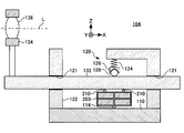
- FIG. 3 is a schematic diagram of an active rotary joint device 106.
- FIG. 2 is a schematic cross-sectional view of a camera system 500.
- FIG. 2 is a cross-sectional view of a lens unit 600.
- FIG. 4 is a schematic cross-sectional view of a vibration actuator unit 400.
- FIG. 4 is a schematic diagram of an electromechanical transducer 420.
- FIG. It is a wave form diagram of a drive signal.
- FIG. 5 is a schematic diagram showing the operation of the electromechanical transducer 420.
- 2 is a cross-sectional view of a lens unit 601.
- FIG. 2 is a schematic plan view of a stage device 450.
- FIG. 3 is a schematic cross-sectional view of a stage device 451.
- FIG. 3 is a schematic cross-sectional view of a stage device 451.
- FIG. 3 is a schematic cross-sectional view of a stage device 451.
- FIG. 1 is a schematic cross-sectional
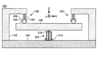
- FIG. 1 is a schematic cross-sectional view of the stage apparatus 101.
- the stage apparatus 101 includes a base 110, an urging unit 120, a moving stage 130, and a vibration actuator unit 201.
- the urging unit 120 and the vibration actuator unit 201 are arranged on the upper surface of the flat base 110.
- the vibration actuator unit 201 is fixed to the upper surface of the base 110 by the fixing portion 112.
- the moving stage 130 is supported from below by the vibration actuator unit 201.
- the urging unit 120 includes a support 122, an elastic member 124, a spherical seat 126, and a rolling ball 128.
- the support column 122 extends upward in the drawing from the upper surface of the base 110, and further extends laterally and is extended upward in the drawing of the moving stage 130.
- An elastic member 124, a spherical seat 126 and a rolling ball 128 are stacked between the tip of the support column 122 and the upper surface of the moving stage 130.
- the rolling ball 128 contacts the upper surface of the moving stage 130.
- the spherical seat 126 prevents the rolling ball 128 from being displaced on the surface of the moving stage 130 while allowing the rolling ball 128 to roll.
- the elastic member 124 is sandwiched between the support 122 and the spherical seat 126 in a compressed state. As a result, the spherical seat 126 and the rolling ball 128 are pressed downward from the upper end of the column 122.
- the urging units 120 as described above are provided at a plurality of locations on the moving stage 130 and cooperate to urge the moving stage 130 downward, in other words, in a direction approaching the base 110. Since the moving stage 130 is supported from below by the vibration actuator unit 201, the contact portion 210 disposed on the upper end of the vibration actuator unit 201 is pressed toward the lower surface of the moving stage 130.
- the structure of the urging unit 120 is not limited to the illustrated example.
- the urging unit 120 is provided for the purpose of maintaining a state in which the abutting portion 210 of the vibration actuator unit 201 and the driven surface of the movable stage 130 to be driven are in contact with each other.
- An urging unit 120 that generates an urging force using another method such as fluid pressure may be provided.
- FIG. 2 is a schematic exploded perspective view of the vibration actuator unit 201.
- the vibration actuator unit 201 includes a contact portion 210, a piezoelectric body 220, a common electrode 235, and a plurality of individual electrodes 231, 232, 233, and 234.
- the abutting portion 210 is fixed to the upper surface of the piezoelectric body 220 in the drawing, protrudes from the surface of the piezoelectric body 220, and contacts the lower surface of the moving stage 130 in the drawing.
- the contact portion 210 vibrates together with the piezoelectric body 220.
- the piezoelectric body 220 is formed of a piezoelectric material such as PZT.
- the piezoelectric material expands and contracts in a previously polarized direction when a voltage is applied.
- polarization is performed so that the direction indicated by the arrow Z in the figure is the polarization axis direction. Therefore, when a driving voltage whose voltage value changes periodically is applied, the piezoelectric body 220 generates mechanical vibration that expands and contracts in the direction indicated by the arrow Z in the drawing.
- the individual electrodes 231, 232, 233, 234 and the common electrode are formed of a conductive material such as metal and are insulated from each other.
- the common electrode 235 has substantially the same area as the adjacent piezoelectric body 220 and is coupled to a reference potential, for example, a ground potential. In other words, the entire piezoelectric body 220 is divided into two blocks by the common electrode 235.
- the individual electrodes 231, 232, 233, and 234 are disposed at positions facing the common electrode 235 with the piezoelectric body 220 interposed therebetween.
- a plurality of piezoelectric material blocks 221, 222, 223, and 224 sandwiched between any of the individual electrodes 231, 232, 233, and 234 and the common electrode 235 are formed on the piezoelectric body 220.
- the individual electrodes 231, 232, 233 and 234 are arranged along the arrangement direction of the piezoelectric material blocks 221, 222, 223 and 224.
- the piezoelectric body 220 and the individual electrodes 231, 232, 233, and 234 form an electromechanical transducer that converts electrical vibration of the applied drive voltage into mechanical vibration.
- the contact portion 210, the piezoelectric body 220, the individual electrodes 231, 232, 233, and 234 and the common electrode 235 are in close contact with each other.
- Such a vibration actuator unit 201 is not necessarily manufactured by combining components having the illustrated shape.
- the same structure as the illustrated vibration actuator unit 201 can be formed by sequentially laminating a piezoelectric material and a conductive material, each of which is layered.
- each electrode 231, 232, 233, 234 and the common electrode 235 are arranged on a plane parallel to the arrow Y in the drawing.
- each electrode can be disposed on the other surface or the corner of the piezoelectric body 220.
- the piezoelectric body 220 can be formed in a cylindrical shape, and electrodes can be disposed on the inner surface thereof.
- FIG. 3 is a schematic side view of the vibration actuator unit 201.
- FIG. 3 shows a state where the vibration actuator unit 201 is viewed from the direction indicated by the arrow X in FIGS. 1 and 2, that is, the direction orthogonal to some of the individual electrodes 231 and 232. Elements that are the same as those in FIG. 2 are given the same reference numerals, and redundant descriptions are omitted.
- the individual electrodes 231 and 232 are arranged by dividing the piezoelectric body 220 into left and right in the drawing. Temporarily, the B phase drive signal applied to the individual electrode 232 located on the left side in the figure and the C phase drive signal applied to the individual electrode 233 located behind the individual electrode 232 across the piezoelectric body 220 have the same phase. The voltage is changed periodically. In addition, the A phase drive signal applied to the individual electrode 231 located on the right side in the figure and the D phase drive signal applied to the individual electrode 234 located behind the individual electrode 231 with the piezoelectric body 220 interposed therebetween have the same phase. The voltage is assumed to change periodically.
- FIG. 4 is a diagram illustrating an example of a drive signal waveform supplied to the vibration actuator unit 201. As illustrated, the A-phase drive signal and the D-phase drive signal are synchronized with each other. The B phase drive signal and the C phase drive signal are also synchronized with each other. The A-phase drive signal and the D-phase drive signal have phases advanced by 90 ° with respect to the B-phase drive signal and the C-phase drive signal.
- FIG. 5 is a schematic diagram for explaining the operation of the vibration actuator unit 201 when a drive signal having the above combination is applied to the vibration actuator unit 201. Elements that are the same as those in FIG. 3 are given the same reference numerals, and redundant descriptions are omitted.
- the voltage of the A-phase drive signal and the D-phase drive signal is the same as that of the B-phase drive signal and the C-phase drive signal during the period where the phase of the A-phase drive signal is from 0 to 135 ° and the period of 315 ° or more. Higher than voltage.
- the piezoelectric material blocks 221 and 224 are relatively longer than the piezoelectric material blocks 222 and 223, and the piezoelectric body 220 has a contact portion 210 at the upper end on the right side in the drawing. Bend to displace toward.
- the piezoelectric material blocks 222 and 223 are relatively longer than the piezoelectric material blocks 221 and 224, and the piezoelectric body 220 is bent so that the contact portion 210 at the upper end is displaced to the left in the drawing. To do.
- the voltage values of all the drive signals are positive during the period in which the phase of the A-phase drive signal is 90 ° to 180 °.
- the voltage values of all the drive signals are negative. Therefore, the length of the entire piezoelectric body 220 is relatively larger in the former period than in the latter period.
- FIG. 6 is a schematic side view of the vibration actuator unit 201.
- FIG. 6 shows a state where the vibration actuator unit 201 is viewed from the direction indicated by the arrow Y in FIGS. 1 and 2, that is, the surface direction of the individual electrodes 231 and 234 and the common electrode 235. Elements that are the same as those in FIG. 2 are given the same reference numerals, and redundant descriptions are omitted.
- the individual electrodes 231 and 234 sandwich the piezoelectric body 220 between the common electrode 235 and the individual electrodes 231 and 234, respectively.
- the A-phase drive signal applied to the individual electrode 231 located on the left side in the drawing and the B-phase drive signal applied to the individual electrode 232 adjacent to the individual electrode 231 periodically change in voltage with the same phase.
- the D-phase drive signal applied to the individual electrode 234 located on the right side in the drawing and the C-phase drive signal applied to the individual electrode 233 adjacent to the individual electrode 234 periodically change the voltage with the same phase.
- FIG. 7 is a diagram illustrating an example of a drive signal waveform supplied to the vibration actuator unit 201.
- the A-phase drive signal and the B-phase drive signal are synchronized with each other.
- the D-phase drive signal and the C-phase drive signal are also synchronized with each other.
- the A-phase drive signal and the B-phase drive signal have phases advanced by 90 ° with respect to the D-phase drive signal and the C-phase drive signal.
- FIG. 8 is a schematic diagram for explaining the operation of the vibration actuator unit 201 when a drive signal having the above combination is applied to the vibration actuator unit 201. Elements that are the same as those in FIG. 6 are given the same reference numerals, and redundant descriptions are omitted.
- the voltage of the A-phase drive signal and the B-phase drive signal is the same as that of the D-phase drive signal and the C-phase drive signal during the period from 0 to 135 ° and the phase of 315 ° or more. Higher than voltage.
- the piezoelectric material blocks 221 and 222 are relatively longer than the piezoelectric material blocks 224 and 223, and the piezoelectric body 220 has a contact portion 210 at the upper end on the left side in the figure. Bend to displace.
- the piezoelectric material blocks 221 and 222 are relatively longer than the piezoelectric material blocks 224 and 223, and the piezoelectric body 220 is bent so as to displace the contact portion 210 at the upper end to the right in the drawing. To do.
- the voltage values of all the drive signals are positive.
- the voltage values of all the drive signals are negative. Therefore, the length of the entire piezoelectric body 220 is relatively larger in the former period than in the latter period.
- the vibration actuator unit 201 can move the moving stage 130 in the direction of the arrow X and the direction of the arrow Y. Further, a drive signal in which the drive signal shown in FIG. 4 and the drive signal shown in FIG. 7 are superimposed is added to the vibration actuator unit 201, so that the direction of the arrow X and the direction of the arrow Y are combined. Also, the moving stage 130 can be moved.
- the vibration actuator unit 201 is a single actuator, the moving stage 130 can be moved two-dimensionally by changing the combination of drive signals. 1 shows a single vibration actuator unit 201, it goes without saying that a plurality of vibration actuator units 201 may be provided.
- FIG. 9 is a schematic cross-sectional view of the stage apparatus 102.
- the stage apparatus 102 has the same structure as the stage apparatus 101 shown in FIG. 1 except for the parts described below. Therefore, common elements are denoted by the same reference numerals as those of the stage apparatus 101, and redundant description is omitted.
- the stage apparatus 102 differs from the stage apparatus 101 in that it includes a vibration actuator unit 202.
- the vibration actuator unit 202 has a single support portion 114 projecting downward on the lower surface in the drawing.
- the support part 114 abuts on the upper surface of the base 110 and supports and fixes the vibration actuator unit 202 at a single point.
- the vibration actuator unit 202 has a pair of contact portions 210 on the upper surface in the drawing.
- the point that the moving stage 130 is urged downward by the urging unit 120 is the same as that of the vibration actuator unit 201.
- each of the pair of contact portions 210 contacts the lower surface of the moving stage 130 and supports the moving stage 130 from below.
- FIG. 10 is a schematic exploded perspective view of the vibration actuator unit 202.
- the vibration actuator unit 202 includes a pair of contact portions 210, a piezoelectric body divided into a plurality of piezoelectric material blocks 221, 222, 223, and 224, a common electrode 235, and a plurality of individual electrodes 231, 232, 233, and 234, respectively.
- the piezoelectric material blocks 221, 222, 223, and 224 are all polarized in the longitudinal direction, that is, in the direction shown by the arrow X in the drawing in the state shown in FIG.
- a left wing block 228 corresponding to the left half in the figure is separated by individual electrodes 231 and 232 and a common electrode 235 arranged horizontally in the figure, and a pair of piezoelectric elements arranged vertically in the figure.
- Material blocks 221 and 222 are formed.
- the individual electrodes 231 and 232 are arranged in the arrangement direction of the piezoelectric material blocks 221 and 222.
- a right wing block 229 corresponding to the right half in the figure is divided by individual electrodes 233 and 234 and a common electrode 235 arranged vertically in the figure, and a pair arranged horizontally in the figure.
- the piezoelectric material blocks 223 and 224 are formed.
- the individual electrodes 233 and 234 are arranged in the arrangement direction of the piezoelectric material blocks 223 and 224.
- the left wing block 228 of the vibration actuator unit 202 bends in a plane perpendicular to the surface of the base 110 in the stage device 102.
- the right wing block 229 of the vibration actuator unit 202 causes mechanical vibration that bends in a plane parallel to the surface of the base 110 in the stage device 102. Arise.
- One of the pair of abutting portions 210 is arranged at the approximate center in the surface direction in the individual electrode 231 located on the upper surface of the left wing block 228.
- the other abutting portion 210 is disposed at the approximate center of the upper surface formed when the individual electrodes 233 and 234, the piezoelectric material blocks 223 and 224, and the common electrode 235 of the right wing block 229 are brought into close contact with each other.
- These contact portions 210 vibrate together when either the piezoelectric material blocks 221 and 222 or the piezoelectric material blocks 223 and 224 vibrate, respectively.
- the vibration actuator unit 202 in use is in a state in which the illustrated abutting portion 210, piezoelectric material blocks 221, 222, 223, 224, individual electrodes 231, 232, 233, 234 and common electrode 235 are in close contact with each other. is there.
- Such a vibration actuator unit 202 is not necessarily manufactured by combining components having the illustrated shape.
- the same structure as the illustrated vibration actuator unit 201 can be formed by sequentially laminating a piezoelectric material and a conductive material, each of which is layered.
- the support portion 114 and the contact portion may be adhered and attached.
- a poticon (trade name) having little deformation and wear resistance can be used.
- FIG. 11 is a diagram showing drive signal waveforms applied to the individual electrodes 231, 232, 233 and 234 of the vibration actuator unit 202.
- the individual electrode 231 has an A phase drive signal
- the individual electrode 232 has a B phase drive signal
- the individual electrode 233 has a C phase drive signal
- the individual electrode 234 has a D phase. It is assumed that the drive signals are individually applied.
- the A-phase drive signal and the B-phase drive signal are 180 ° out of phase and have inverted signal waveforms.
- the piezoelectric material blocks 221 and 222 in the vibration actuator unit 202 are within the plane orthogonal to the upper surface of the base 110 of the stage device 102 as described above. A bending mechanical vibration is generated.
- the C-phase driving signal and the D-phase driving signal are synchronized with each other and have the same signal waveform.
- the piezoelectric material blocks 223 and 224 in the vibration actuator unit 202 expand and contract integrally.
- the expansion / contraction direction of the piezoelectric material blocks 223 and 224 is the direction indicated by the arrow X in FIGS.
- the vibration actuator unit 202 causes the moving stage 130 to move in the stage apparatus 102. It is moved in the direction indicated by arrow X in the figure.
- the moving direction of the moving stage 130 is reversed.
- FIG. 12 is a diagram showing other drive signal waveforms applied to the individual electrodes 231, 232, 233, 234 of the vibration actuator unit 202.
- the A-phase drive signal and the B-phase drive signal are 180 ° out of phase and have inverted signal waveforms. Therefore, as described above, the piezoelectric material blocks 221 and 222 generate mechanical vibration that bends in a plane orthogonal to the upper surface of the base 110 of the stage apparatus 102.
- the C-phase drive signal and the D-phase drive signal also have signal waveforms that are inverted from each other with a phase shift of 180 °. Therefore, the piezoelectric material blocks 223 and 224 generate mechanical vibration that bends in a plane parallel to the surface of the base 110 of the stage apparatus 102.
- the vibration actuator unit 202 causes the stage 130 to move the moving stage 130. , In the direction opposite to the direction indicated by the arrow Y in the figure.
- the moving direction of the moving stage 130 is reversed.
- the vibration actuator unit 202 can move the moving stage 130 in the direction of the arrow X and the direction of the arrow Y. Furthermore, the moving direction of the moving stage 130 can be changed by variously changing the delay relationship between the driving signals from the A phase to the D phase.
- the vibration actuator unit 202 is a single actuator, the moving stage 130 can be moved two-dimensionally by changing the combination of drive signals.
- a single vibration actuator unit 201 is provided in the stage apparatus 102 in FIG. 9, it goes without saying that a plurality of vibration actuator units 202 may be provided according to an assumed load.
- FIG. 13 is a schematic cross-sectional view of the stage apparatus 103.
- the stage apparatus 103 has the same structure as the stage apparatus 102 shown in FIG. 9 except for the parts described below. Therefore, the same reference numerals as those of the stage apparatus 102 are assigned to the common elements, and redundant description is omitted.
- the stage apparatus 102 differs from the stage apparatus 102 in that it includes a vibration actuator unit 203.
- the vibration actuator unit 203 is different from the vibration actuator unit 202 in the arrangement of the piezoelectric material blocks 221, 222, 223 and 224 formed by the individual electrodes 231, 232, 233 and 234 and the common electrode 235.
- FIG. 14 is a schematic exploded perspective view of the vibration actuator unit 203.
- the vibration actuator unit 203 includes a pair of contact portions 210, a piezoelectric body 220 divided into a plurality of piezoelectric material blocks, a common electrode 235, and a plurality of individual electrodes 231, 232, 233, and 234, respectively.
- the piezoelectric material blocks 221, 222, 223, and 224 are all polarized in the longitudinal direction, that is, in the direction shown by the arrow X in the drawing in the state shown in FIG.
- the piezoelectric body 220 is divided into a pair of piezoelectric bodies 220 arranged in a direction perpendicular to the longitudinal direction by a common electrode 235 arranged in the longitudinal direction. Furthermore, four individual electrodes 231, 232, 233, and 234 that divide the surface into four parts vertically and horizontally are disposed on the surface facing the common electrode 235 in each of the pair of piezoelectric bodies 220.
- each of the eight piezoelectric material blocks 221, 222, 223, and 224 includes one apex of the piezoelectric body 220 that forms a hexahedron as a whole.
- a pair having the same reference number is arranged at diagonal positions of the piezoelectric body 220 that forms a hexahedron as a whole, and has the same phase drive signal in common. To receive.
- the left wing block 228 corresponding to the left half in the drawing and the right wing block 229 corresponding to the right half in the drawing each operate similar to the vibration actuator unit 201 shown in FIG. .
- these blocks are coupled in a state of being rotated around a common rotation axis in the longitudinal direction of the piezoelectric body 220, the behavior of the left half in the figure and the right half in the figure is different. Arise.
- the vibration actuator unit 203 the amplitude of vibration generated in the piezoelectric body 220 when a drive signal is supplied is increased. Therefore, in the stage apparatus 103, the moving stage 130 is driven efficiently.
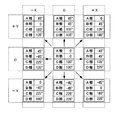
- FIG. 15 is a diagram showing a phase relationship of drive signals applied to the individual electrodes 231, 232, 233, and 234 of the vibration actuator unit 203.
- the symbols X and Y described in the upper and left columns indicate the moving direction of the moving stage 130 driven by the vibration actuator unit 203 corresponding to the arrows X and Y shown in FIG. 13. Show.
- the moving direction of the moving stage 130 can be changed by variously changing the delay relationship between the driving signals from the A phase to the D phase.
- the vibration actuator unit 203 drives the eight piezoelectric material blocks 221, 222, 223, and 224 with four-phase driving signals, thereby moving the moving stage 130. It can be moved both in the direction of arrow X and in the direction of arrow Y. Further, the moving direction of the moving stage 130 can be changed by changing the phase delay relationship between the drive signals.
- the vibration actuator unit 203 is a single actuator, the moving stage 130 can be moved two-dimensionally by changing the combination of drive signals.
- the stage apparatus 102 of FIG. 9 is provided with a single vibration actuator unit 203, a plurality of vibration actuator units 203 may be provided according to an assumed load.
- FIG. 16 is a schematic cross-sectional view of the optical device 104.
- the optical device 104 includes a vibration actuator unit 203.
- the same reference numerals are assigned to elements common to the stage apparatus 103 shown in FIG.
- the optical device 104 has a unique structure in that it includes a moving shaft 132 instead of the moving stage 130 in the stage device 102.
- the moving shaft 132 is inserted through a bearing portion 121 provided on the support column 122 and supported from the base 110 so as to be slidable in the direction indicated by an arrow X in the drawing. Further, the moving shaft 132 is supported by the bearing portion 121 so as to be rotatable around the central axis in the longitudinal direction.
- the moving shaft 132 holds a lens 136 constituting a part of the optical system in a holding frame 134 attached to one end on the outer side of the base 110. Therefore, the lens 136 moves along the optical axis L parallel to the central axis of the moving shaft 132 when the moving shaft 132 slides in the longitudinal direction.
- FIG. 17 is a schematic perspective view of the optical device 104. Elements that are the same as those in FIG. 16 are given the same reference numerals, and redundant descriptions are omitted. FIG. 17 is drawn with the base 110 and the support column 122 omitted.
- the abutting portion 210 of the vibration actuator unit 203 abuts on the cylindrical peripheral surface of the moving shaft 132 to transmit the driving force. Therefore, when the vibration actuator unit 203 generates a driving force in the direction of the arrow X shown in FIG. 16, the moving shaft 132 moves in the direction of its own central axis.
- the moving shaft 132 when the vibration actuator unit 203 generates a driving force in the direction of the arrow Y shown in FIG. 16, the moving shaft 132 has its own central axis as shown by the arrow Q in FIG. Rotate around. When the moving shaft 132 rotates, the lens 136 deviates from the optical axis L.
- the lens 136 which is an optical member, can be moved in a direction away from the optical axis L in addition to the optical axis L direction. Therefore, in addition to moving the lens 136 to change the characteristics of the optical system, the optical configuration itself can be changed by removing the lens 136 from the optical system.
- the optical device 104 is formed using the vibration actuator unit 203.
- the optical device 104 may be formed using the other vibration actuator units 201 and 202 already described.
- FIG. 18 is a schematic cross-sectional view of the optical device 105, and shows a cross section orthogonal to the optical axis L of the optical system including the lens 136. Elements that are the same as those in FIG. 17 are given the same reference numerals, and redundant descriptions are omitted.
- the optical device 105 includes a lens barrel 116, leaf springs 125 and 127, a holding frame 134, a lens 136, and a vibration actuator unit 203.
- a holding frame 134 that holds the lens 136 is coupled to a pair of leaf springs 125 and 127.
- Each vibration actuator unit 203 has the same structure as the vibration actuator unit 203 already described, and can move with respect to the inner surface of the lens barrel 116 in a direction perpendicular to the paper surface and a direction parallel to the paper surface. .
- the pair of leaf springs 125 and 127 are biased in the extending direction, and the respective end portions press the vibration actuator unit 203 toward the inner surface of the lens barrel 116.
- the holding frame 134 and the lens 136 are held at substantially the center of the lens barrel 116 in the drawing.
- the inclination of the lens 136 with respect to the optical axis L changes.
- the lens 136 translates in the direction of the optical axis L while maintaining an angle with respect to the optical axis L.
- the lens 136 moves in parallel with the paper surface as indicated by an arrow X in the figure while maintaining the inclination with respect to the optical axis L.
- FIG. 19 is a schematic cross-sectional view for explaining another operation of the optical device 105 shown in FIG. Elements that are the same as those in FIG. 18 are given the same reference numerals, and redundant descriptions are omitted.
- the pair of the vibration actuator unit 203 disposed on the lower side in the figure, as indicated by the arrow M 2 in the figure, moves in parallel to the paper surface in a direction away from each other.
- the vibration actuator unit 203 By the operation of the vibration actuator unit 203 as described above, the upper portions of the leaf springs 125 and 127 in the drawing approach to be parallel to the side surface of the lens barrel 116.
- the lower part of the leaf springs 125 and 127 in the figure has a large inclination with respect to the side surface of the lens barrel 116.
- the lens 136 as shown by arrow M 3 in the figure, translates towards the position of the lower in the lens barrel 116.
- the vibration actuator unit 203 on the upper side in the figure and the vibration actuator unit 203 on the lower side in the figure perform different operations, so that the lens 136 can be moved up and down in the figure. Furthermore, by combining the operations of the vibration actuator unit 203, the optical adjustment of the lens 136 can be executed by electrical control with respect to the vibration actuator unit 203.
- the optical device 105 is formed using the vibration actuator unit 203.
- the optical device 105 may be formed using the other vibration actuator units 201 and 202 already described.
- FIG. 20 is a schematic perspective view of the active rotary joint device 106.
- the active rotary joint device 106 includes a base 110, an urging unit 120, a driven sphere 138, and a vibration actuator unit 203.
- the vibration actuator unit 203 is fixed to the base 110 by bringing the support portion 114 into contact with the upper surface of the base 110.
- the driven sphere 138 comes into contact with the contact portion 210 of the vibration actuator unit 203 and is supported and fixed from below in the figure.
- the urging unit 120 includes a column 122 extending upward in the drawing from the base 110, an elastic member 124 suspended from the column 122, and a spherical seat 126 urged downward by the elastic member 124. .
- the spherical seat 126 urges the driven sphere 138 downward. Therefore, the driven sphere 138 is pressed against the contact portion 210 of the vibration actuator unit 203.
- the vibration actuator unit 203 When the vibration actuator unit 203 operates in the active rotary joint device 106 as described above, the driven sphere 138 rotates while maintaining the same position. Thereby, the movable limb 139 attached to the driven sphere 138 changes the inclination with respect to the base 110.
- the vibration actuator unit 203 generates a driving force in an arbitrary direction with respect to the surface direction of the base 110. Therefore, the active rotary joint device 106 can change the inclination of the movable limb 139 by electrical control of the driving power supplied to the vibration actuator unit 203.
- the active rotary joint device 106 is formed using the vibration actuator unit 203.
- the active rotary joint device 106 may be formed using the other vibration actuator units 201 and 202 already described.
- FIG. 21 is a schematic sectional view of the camera system 500.
- the camera system 500 includes a lens unit 600 and a camera body 300.
- the side on which the object to be imaged of the camera system 500 is located is described as the front side or the front end side.
- the side on which the camera body 300 is disposed with respect to the lens unit 600 is referred to as a rear side or a back side.
- the lens unit 600 includes a fixed cylinder 610, lens groups 620, 630, and 640, a lens side control unit 650, and a vibration actuator unit 400.
- a lens side mount portion 660 is provided at the rear end of the fixed cylinder 610.
- the lens side mount portion 660 is fitted with the body side mount portion 360 of the camera body 300 to couple the lens unit 600 to the camera body 300. Since the coupling between the lens side mount portion 660 and the body side mount portion 360 can be released, the lens unit 600 can be replaced with another lens unit 600 having the lens side mount portion 660 of the same standard.
- the lens groups 620, 630, and 640 are arranged along the optical axis X inside the fixed cylinder 610 to form an optical system. At least one lens group 630 is supported by a holding frame 632 having a fitting portion 634 and an engaging portion 636.
- the fitting portion 634 is fitted to the guide shaft 612. Further, the engaging portion 636 engages with the guide shaft 612.
- the guide shaft 612 is arranged in parallel with the optical axis X of the optical system and is fixed to the fixed cylinder 610. Therefore, the holding frame 632 is slidably supported along the guide shaft 612.
- the holding frame 632 is integrally coupled to the vibration actuator unit 400.
- the vibration actuator unit 400 includes an urging unit 410 and an electromechanical conversion element 420.
- the urging unit 410 presses the electromechanical conversion element 420 toward the guide shaft 612.
- the electromechanical transducer 420 generates vibration by the supplied driving power and generates a driving force that moves the holding frame 632 along the guide shaft 612.
- a magnetic sensor 430 disposed to face the vibration actuator unit 400 is fixed to the inner surface of the fixed cylinder 610.
- the magnetic sensor 430 is used when detecting the positions of the urging unit 410 and the electromechanical transducer 420.
- the lens side control unit 650 includes a drive circuit that outputs the drive power of the vibration actuator unit 400 and controls the entire lens unit 600.
- the lens side control unit 650 is also responsible for communication between the body side control unit 322 mounted on the camera body 300 and the lens unit 600 side. Thereby, the lens unit 600 attached to the camera body 300 operates in cooperation with the camera body 300.
- the camera body 300 includes a mirror unit 370 on the rear side of the body side mount portion 360.
- the mirror unit 370 has a main mirror holding frame 372 and a main mirror 371.
- the main mirror holding frame 372 is supported by a main mirror rotating shaft 373 while holding the main mirror 371.
- the mirror unit 370 has a sub mirror holding frame 375 and a sub mirror 374.
- the sub mirror holding frame 375 is pivotally supported from the main mirror holding frame 372 by a sub mirror rotating shaft 376 while holding the sub mirror 374.
- the sub mirror 374 and the sub mirror holding frame 375 rotate with respect to the main mirror holding frame 372 while moving together with the main mirror holding frame 372.
- a focusing screen 352 and a pentaprism 354 are sequentially arranged above the mirror unit 370 in the drawing.
- a finder optical system 356 and a photometric sensor 390 are disposed behind the pentaprism 354 in the drawing.
- the rear end of the viewfinder optical system 356 is exposed as a viewfinder 350 on the back surface of the camera body 300.
- the photometric sensor 390 detects the intensity of incident light.
- a focal plane shutter 310 In the camera body 300, a focal plane shutter 310, an optical filter 332, and an image sensor 330 are sequentially arranged behind the mirror unit 370 in the drawing.
- the focal plane shutter 310 opens and closes to open or shield the image sensor 330 against incident light.
- the optical filter 332 is installed immediately before the image sensor 330 and removes infrared rays and ultraviolet rays from the light incident on the image sensor 330.
- the optical filter 332 protects the surface of the image sensor 330.
- the optical filter 332 includes a low-pass filter that reduces the spatial frequency of the incident light. Thereby, the optical filter 332 removes the spatial frequency component exceeding the Nyquist frequency of the image sensor 330 from the incident light, and suppresses the generation of moire.
- the imaging element 330 is formed by a photoelectric conversion element such as a CCD sensor or a CMOS sensor, and receives incident light that has passed through the optical filter 332.
- a substrate 320 and a rear display unit 340 are sequentially arranged behind the image sensor 330.
- a body side control unit 322, an image processing unit 324, and the like are mounted on the substrate 320.
- the rear display unit 340 is formed of a liquid crystal display panel or the like, and is exposed on the rear surface of the camera body 300.
- the main mirror 371 in the state shown in the figure is at an observation position that obliquely crosses the light incident through the lens unit 600.
- the main mirror 371 has a reflection region that reflects incident light and a half mirror region that transmits part of the incident light.
- Part of the subject light incident on the main mirror 371 at the observation position passes through the half mirror region and enters the sub mirror 374.
- the sub mirror 374 reflects the incident light downward in the figure, and makes the incident light enter the focus sensor 382 through the focusing optical system 380 arranged in the lower part of the mirror unit 370 in the figure.
- the reflection region of the main mirror 371 at the observation position reflects the light incident through the lens unit 600 toward the focusing screen 352.
- the focusing screen 352 is disposed at a position optically conjugate with the element arrangement surface of the image sensor 330 and visualizes an image formed by the optical system of the lens unit 600.
- the subject image connected to the focusing screen 352 is observed as an erect image from the viewfinder 350 through the pentaprism 354 and the viewfinder optical system 356.
- the photometric sensor 390 disposed above the finder optical system 356.
- the photometric sensor 390 detects the light intensity of the received light.
- the body-side control unit 322 calculates subject brightness according to the detected light intensity, and calculates imaging conditions such as an aperture value, shutter speed, and ISO sensitivity according to the calculated subject brightness. As a result, the camera system 500 is in a state where it can shoot a subject under appropriate shooting conditions.
- the focus sensor 382 detects the defocus amount in the optical system of the lens unit 600 and notifies the body side control unit 322 of it.
- the body-side control unit 322 calculates a movement amount of the lens group 630 sufficient to cancel the detected defocus amount, and notifies the lens-side control unit 650 of the movement amount.
- the lens-side control unit 650 drives the lens group 630 by operating the vibration actuator unit 400 according to the notified movement amount. As a result, the subject image formed by the optical system of the lens unit 600 becomes clear on the focusing screen 352.
- the main mirror holding frame 372 rotates clockwise together with the main mirror 371 in the drawing and stops substantially horizontally at the shooting position. As a result, the main mirror 371 retracts from the optical path of the incident light through the optical system of the lens unit 600.
- the sub mirror holding frame 375 When the main mirror 371 rotates toward the shooting position, the sub mirror holding frame 375 also moves up with the main mirror holding frame 372 and rotates around the sub mirror rotation shaft 376 and stops substantially horizontally at the shooting position. To do. As a result, the sub mirror 374 is also retracted from the optical path of the incident light.
- the front curtain of the focal plane shutter 310 is subsequently opened. Thereby, the light incident through the optical system of the lens unit 600 passes through the optical filter 332 and is received by the image sensor 330 and imaged. Thereafter, the rear film of the focal plane shutter 310 is closed, the main mirror 371 and the sub mirror 374 are returned to the observation position again, and a series of operations related to photographing is completed.
- the vibration actuator unit 400 is applied to the lens unit 600 in the camera system 500 of the interchangeable lens single-lens reflex camera. It can be used for the purpose of moving the optical member in the lens unit of the apparatus.
- the present invention is not limited to the imaging device, and can be widely used when driving a member positioned with high positioning accuracy, including an optical device such as a microscope provided with an optical member.
- the present invention is not limited to optical devices, and can be widely used as actuators for stage devices and the like.
- FIG. 22 is a cross-sectional view schematically showing a cross section orthogonal to the optical axis X of the lens unit 600. Elements that are the same as those in FIG. 21 are given the same reference numerals, and redundant descriptions are omitted.
- the holding frame 632 that holds the lens group 630 is integrally provided with a fitting portion 634 at the upper end in the drawing.
- the fitting portion 634 surrounds the guide shaft 612 together with the electromechanical conversion element 420. Thereby, the holding frame 632 is fitted to the guide shaft 612 in a state where the holding frame 632 can rotate around the guide shaft 612.
- the holding frame 632 is integrally provided with an engaging portion 636 at the lower end in the drawing.
- the engaging portion 636 has parallel surfaces with substantially the same interval as the outer diameter of the guide shaft 612, and sandwiches the guide shaft 612 between the parallel surfaces. Thereby, the lower side of the holding frame 632 is prevented from being displaced parallel to the paper surface and horizontally in the drawing. Therefore, the holding frame 632 is positioned in the direction parallel to the paper surface by the fitting portion 634 and the engaging portion 636.
- the magnetic sensor 430 is fixed to the inner surface of the fixed cylinder 610 so as to face the upper surface of the urging portion 410.
- the urging unit 410 moves along with the holding frame 632 perpendicular to the paper surface. Therefore, the magnetic sensor 430 and the urging unit 410 do not necessarily face each other at the same position in the direction perpendicular to the paper surface.
- FIG. 23 is a schematic diagram showing the overall structure of the vibration actuator unit 400. Elements common to FIGS. 21 and 22 are denoted by the same reference numerals, and redundant description is omitted.
- the vibration actuator unit 400 includes an urging unit 410, an electromechanical conversion element 420, and a magnetic sensor 430.
- the vibration actuator unit 400 in the lens unit 600 is supplied with driving power from the lens-side control unit 650 and operates under the control of the lens-side control unit 650.
- the electromechanical transducer 420 has a support part 422, a contact part 424 and a piezoelectric body 425.
- the piezoelectric body 425 is formed of a rectangular parallelepiped piezoelectric material.
- the pair of contact portions 424 are arranged on the lower surface of the piezoelectric body 425 in the drawing and are in contact with the guide shafts 612, respectively.
- the support portion 422 is disposed on the upper surface of the piezoelectric body 425 in the drawing.
- the support portion 422 contacts the urging portion 410 from below in the drawing and receives the urging force from the urging portion 410.
- the electromechanical conversion element 420 is urged downward in the figure, and the contact portion 424 is pressed toward the guide shaft 612.
- the urging unit 410 includes a permanent magnet 412, a yoke 414, and a buffer member 416.
- the yoke 414 is made of a magnetic material and is disposed along the side surface from the upper surface of the electromechanical transducer 420 in the drawing. The lower end of the yoke 414 approaches the guide shaft 612 but does not contact it.
- the permanent magnet 412 is placed on the yoke 414 so that the magnetic poles are arranged in a direction parallel to the guide shaft 612. Therefore, the yoke 414 is also magnetized by the permanent magnet 412.
- the guide shaft 612 is also formed of a magnetic material and forms a part of the urging portion 410. That is, the magnetic field generated by the permanent magnet 412 forms a magnetic circuit by the yoke 414 and the guide shaft 612 that are each a magnetic material. Thereby, the urging portion 410 is attracted toward the guide shaft 612.
- the force that attracts the biasing portion 410 toward the guide shaft 612 is transmitted to the electromechanical transducer 420 as the biasing force through the support portion 422 as described above, and presses the contact portion 424 against the guide shaft 612.
- the electromechanical transducer 420 is preloaded toward the guide shaft 612 by the magnetic force generated by the permanent magnet 412.
- the buffer member 416 is attached to the lower end of the yoke 414, and prevents the guide shaft 612 from rubbing when the lower end of the yoke 414 contacts the guide shaft 612 for some reason. Further, by forming the buffer member 416 with a non-magnetic material, it is possible to prevent the buffer member 416 from sticking to the guide shaft 612 when it contacts the guide shaft 612. Considering these functions, the buffer member 416 is preferably formed using a resin material having elasticity and lubricity, such as POM resin.
- the magnetic sensor 430 detects the magnetic force of the permanent magnet 412 of the urging unit 410 as a physical quantity. Therefore, when the urging unit 410 and the electromechanical transducer 420 are displaced with respect to the fixed cylinder 610, the magnetic sensor 430 detects a change in the magnetic field. Thereby, the lens side control unit 650 can know the position of the holding frame 632 based on the detection result of the magnetic sensor 430. Therefore, the lens-side control unit 650 can adjust the driving power supplied to the vibration actuator unit 400 according to the position of the holding frame 632.
- a Hall element As the magnetic sensor 430, a Hall element, a magnetic impedance element, or the like can be used. A plurality of magnetic sensors 430 may be arranged along the movement path of the vibration actuator unit 400.
- the urging unit 410 has a single permanent magnet 412, but a plurality of permanent magnets 412 may be arranged on the yoke 414. Thereby, a periodic change in the magnetic flux density is detected in the magnetic sensor 430, and the operation amount of the vibration actuator unit 400 can be detected with high accuracy.
- an electromagnet may be used instead of the permanent magnet 412. Since the electromagnet can change the strength of the generated magnetic force, the urging unit 410 using the electromagnet can change the urging force. However, when the magnetic force of the electromagnet is changed, it is preferable to correct the detection result of the magnetic sensor 430 in accordance with the change in the generated magnetic force.
- FIG. 24 is a schematic diagram showing a state in which one of the electromechanical transducer elements 420 is enlarged and viewed from the side. Elements that are the same as those in the other drawings are given the same reference numerals, and redundant descriptions are omitted.
- Each of the electromechanical conversion elements 420 has a pair of A-phase electrodes 421 and B-phase electrodes 423 arranged at diagonal positions of a piezoelectric body 425 that is substantially rectangular when viewed from the side.
- the piezoelectric body 425 is formed of a piezoelectric material such as PZT.
- the A-phase electrode 421 and the B-phase electrode 423 are each formed of a metal material fired together with the piezoelectric body 425.
- the piezoelectric body 425 may be formed by laminating layered piezoelectric materials, or may be in a bulk shape.
- the size of the piezoelectric body 425 formed in this way can be formed to be about 2 mm square by laminating, for example, about 10 layered piezoelectric materials.
- the A-phase electrode 421 and the B-phase electrode 423 are arranged at positions corresponding to the back surface of the piezoelectric body 425 in the direction perpendicular to the paper surface. Therefore, when a drive voltage is applied to the A-phase electrode 421, the piezoelectric body 425 contracts or expands in a region sandwiched between the A-phase electrodes 421. Similarly, when a drive voltage is applied to the B-phase electrode 423, the piezoelectric body 425 contracts or expands in a region sandwiched between the B-phase electrodes 423.
- FIG. 25 is a waveform diagram showing signal waveforms of the A-phase drive signal and the B-phase drive signal supplied to the electromechanical transducer 420.
- the A-phase drive signal and the B-phase drive signal fluctuate periodically.
- the B phase drive signal has a sine wave waveform that is 90 degrees behind the A device drive signal, that is, a cosine wave waveform.
- a voltage signal modulated by the modulation signal is generated as a B-phase drive signal.
- FIG. 26 is a schematic diagram showing the operation of the electromechanical transducer 420 supplied with the A-phase drive signal and the B-phase drive signal as described above. As described above, since the phase of the A-phase drive signal and the B-phase drive signal is shifted from each other, the piezoelectric body 425 is different in the region where the A-phase electrode 421 is disposed and the region where the B-phase electrode 423 is disposed. Extensive state.
- the electromechanical transducer 420 since the A-phase electrode 421 and the B-phase electrode 423 are disposed adjacent to each other, the electromechanical transducer 420 is deformed by bending due to the expansion and contraction of the piezoelectric body 425 as described above. In addition, the electromechanical conversion element 420 is also deformed to expand and contract in the longitudinal direction. As a result, as indicated by an arrow V in the drawing, the contact portion 424 generates an elliptical vibration that draws an elliptical activation in the drawing.
- the contact portion 424 of the electromechanical transducer 420 is pressed toward the guide shaft 612 by the biasing force applied by the biasing portion 410. Therefore, when the contact portion 424 generates the above elliptical vibration, the guide shaft 612 is displaced relative to the electromechanical conversion element 420.
- the contact portion 424 is preferably disposed at a portion corresponding to the antinode of vibration generated in the electromechanical conversion element 420.
- the vibration actuator unit 400 that moves integrally with the holding frame 632 is in contact with the guide shaft 612 at the contact portion 424 that generates the driving force, and is not in contact with other portions. Therefore, there is no place where sliding resistance is generated with the movement of the holding frame 632 driven by the vibration actuator unit 400, and the holding frame 632 can be driven smoothly.
- the drive amount of the vibration actuator unit 400 can be detected by detecting the magnetic flux density of the magnetic field generated by the permanent magnet 412 that is a part of the urging unit 410. Therefore, the operation amount of the vibration actuator unit 400 can be accurately detected without using expensive parts such as a linear scale that occupy a large space.
- the permanent magnet 412 is disposed on the yoke 414 that moves together with the piezoelectric body 425 side.
- the permanent magnet 412 may be disposed on the guide shaft 612 side, and the yoke 414 formed of a magnetic material may be attracted by a magnetic force to generate a biasing force.
- the magnetic sensor 430 is disposed on the piezoelectric body 425 side, and the operation amount of the vibration actuator unit 400 can be detected.
- FIG. 27 is a cross-sectional view of another lens unit 601 provided with the vibration actuator unit 400, and shows a cross section orthogonal to the optical axis X.
- FIG. Elements common to the embodiment shown up to FIG. 26 are denoted by the same reference numerals, and redundant description is omitted.
- the lens unit 601 includes a pair of vibration actuator units 400.
- the fixed cylinder 610 has a guide rail 611 formed integrally with the fixed cylinder 610 instead of the guide shaft 612.
- the guide rail 611 extends in a direction perpendicular to the paper surface, that is, in a direction parallel to the optical axis X of the lens unit 601 while maintaining a constant cross-sectional shape.
- the guide rail 611 forms a pair of flat guide surfaces 613 in the longitudinal direction of the lens unit 601.
- the pair of guide surfaces 613 have different inclinations with respect to the horizontal line in the drawing.
- Each of the pair of vibration actuator units 400 abuts against the pair of guide surfaces 613.
- the contact portion 424 is pressed against the guide surface 613 in different directions by the magnetic force generated by the permanent magnet 412 of the biasing portion 410. Therefore, the holding frame 632 is positioned with respect to the fixed cylinder 610 in any direction in the cross section shown in the figure by the pair of vibration actuator units 400 that generate the suction force with respect to the pair of guide surfaces 613. .
- the holding frame 632 and the fixed cylinder 610 are in contact with each other in the vibration actuator unit 400, and there is no other contact portion. Therefore, when the holding frame 632 is driven by the driving force of the vibration actuator unit 400, sliding resistance does not occur with the movement of the holding frame 632, and the holding frame 632 moves smoothly.
- each of the pair of vibration actuator units 400 can individually detect the movement amount by the magnetic sensor 430 with high accuracy. Therefore, the operation of the pair of vibration actuator units 400 can be synchronized, and the holding frame 632 can be moved without causing an inclination with respect to the optical axis X.
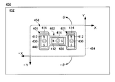
- FIG. 28 is a schematic plan view of a stage apparatus 450 provided with vibration actuator units 401 and 402.
- the stage device 450 includes a surface plate 452, a moving stage 454, and a drive unit 456.
- the moving stage 454 is disposed on a fixed surface plate 452 via a driving unit 456.
- the moving stage 454 is driven by the driving unit 456 and moves in the surface direction of the surface plate 452 with respect to the surface plate 452.
- the drive unit 456 includes a plurality of vibration actuator units 401 and 402.
- the individual structures of the vibration actuator units 401 and 402 are substantially the same as those of the vibration actuator unit 400 shown in FIG. However, each magnetic sensor 430 is embedded in the surface plate 452 at a position facing the permanent magnet 412.
- the pair of vibration actuator units 401 are arranged in parallel to the direction indicated by the arrow Y in the drawing.
- the other vibration actuator unit 402 is arranged in a direction orthogonal to the vibration actuator unit 401 as indicated by an arrow X in the drawing.
- These vibration actuator units 401 and 402 are integrally coupled by a connecting member 440 and further mounted with a moving stage 454. Accordingly, the moving stage 454 moves on the surface plate 452 together with the driving unit 456 in accordance with the operation of the driving unit 456.
- the pair of vibration actuator units 401 are operated synchronously to generate a driving force in the same direction, thereby moving the moving stage in the direction indicated by arrows Y and -Y in the drawing. 454 can be translated. Further, by moving another vibration actuator unit 402 to generate a driving force, the moving stage 454 can be translated in the direction indicated by the arrows X and -X in the drawing.
- stage apparatus 450 when the pair of vibration actuator units 401 are operated differently, the moving stage 454 can be rotated as indicated by arrows ⁇ and ⁇ in the drawing.
- the drive unit 456 by combining the plurality of vibration actuator units 401 and 402, a highly functional stage device 450 can be formed with a simple structure.
- FIG. 29 and 30 are schematic cross-sectional views of another stage device 451.
- FIG. 29 shows a cross section along the moving direction of the moving stage 454, and
- FIG. 30 shows a cross section orthogonal to the cross section of FIG.
- the stage device 451 includes a surface plate 452, a vibration actuator unit 403, and a moving stage 454.
- the moving stage 454 is supported by the vibration actuator unit 403 on a fixed surface plate 452. Accordingly, the moving stage 454 is driven by the vibration actuator unit 403 and moves relative to the surface plate 452 in the surface direction of the surface plate 452.
- the vibration actuator unit 403 includes an urging unit 410 and an electromechanical conversion element 420.
- the structure of the electromechanical transducer 420 is the same as that of the vibration actuator unit 400 shown in FIG. Accordingly, common reference numerals are assigned to the same elements, and redundant description is omitted.
- the urging unit 410 has a communication hole 411 that opens in the immediate vicinity of the surface plate 452.
- the communication hole 411 is coupled to a negative pressure source through the flexible tube 413. As a result, a negative pressure is also generated at the opening at the lower end of the communication hole 411 and the surface of the surface plate 452 is sucked.
- the urging unit 410 generates an urging force that presses the contact portion 424 of the electromechanical conversion element 420 against the surface plate 452, so that when the electromechanical conversion element 420 is operated, the mechanical vibration of the contact portion 424 is constant.
- a driving force is generated between the panel 452 and the vibration actuator unit 403, and the moving stage 454 moves on the surface plate 452.
- the surface plate 452 includes a slit 453, a cavity 455, and a pressure sensor 432.
- the cavity 455 is a cavity formed inside the surface plate 452 and allows the slit 453 and the pressure sensor 432 to communicate with each other.
- the pressure sensor 432 communicates with the cavity 455 at the left end in the figure, that is, at a position biased with respect to the moving direction of the moving stage 454.
- the slit 453 allows the cavity 455 and the outside of the surface plate 452 to communicate with each other.
- the slit 453 is provided on the surface of the surface plate 452 at a position facing the opening of the communication hole 411. Therefore, when the communication hole 411 communicates with the negative pressure source, the communication hole 411 also sucks air inside the slit 453. Thereby, the air in the cavity 455 is also sucked out, and the inside of the cavity 455 is also decompressed.
- the pressure sensor 432 detects such a change in the atmospheric pressure in the cavity 455.
- the vibration actuator unit 403 operates and the moving stage 454 moves on the surface plate 452
- the position where the communication hole 411 and the slit 453 face each other changes, so that the position between the communication hole 411 and the pressure sensor 432 changes.
- the distance D changes. Since the air in the cavity 455 has viscosity, the pressure in the cavity 455 detected by the pressure sensor 432 differs according to the change in the distance D. More specifically, when the distance D is short, the pressure reduction detected by the pressure sensor 432 is large, and when the distance D is long, the pressure reduction detected by the pressure sensor 432 is small.
- the vibration actuator unit 403 can detect the amount of movement by detecting the atmospheric pressure, which is a physical quantity generated by the urging unit 410. Therefore, the movement amount can be monitored and accurately controlled without using additional members such as a linear scale and an encoder.
- stage device 451 may also be provided with a drive unit 456 having a plurality of vibration actuator units 403 whose directions are different from each other, like the stage device 450 shown in FIG. Thereby, the moving stage 454 can be moved two-dimensionally in a plane parallel to the surface of the surface plate 452 and can be rotated on the same plane.
Landscapes
- Physics & Mathematics (AREA)
- General Physics & Mathematics (AREA)
- Optics & Photonics (AREA)
- General Electrical Machinery Utilizing Piezoelectricity, Electrostriction Or Magnetostriction (AREA)
Priority Applications (2)
| Application Number | Priority Date | Filing Date | Title |
|---|---|---|---|
| CN201380043409.5A CN104584415B (zh) | 2012-06-18 | 2013-05-31 | 振动致动器单元、光学装置以及台装置 |
| US14/570,300 US10305397B2 (en) | 2012-06-18 | 2014-12-15 | Vibration actuator unit, stage apparatus, and optical apparatus |
Applications Claiming Priority (4)
| Application Number | Priority Date | Filing Date | Title |
|---|---|---|---|
| JP2012136989A JP2014003791A (ja) | 2012-06-18 | 2012-06-18 | 駆動装置、光学装置およびステージ装置 |
| JP2012-136989 | 2012-06-18 | ||
| JP2012-161999 | 2012-07-20 | ||
| JP2012161999A JP6015188B2 (ja) | 2012-07-20 | 2012-07-20 | 振動アクチュエータユニット、ステージ装置および光学装置 |
Related Child Applications (1)
| Application Number | Title | Priority Date | Filing Date |
|---|---|---|---|
| US14/570,300 Continuation US10305397B2 (en) | 2012-06-18 | 2014-12-15 | Vibration actuator unit, stage apparatus, and optical apparatus |
Publications (1)
| Publication Number | Publication Date |
|---|---|
| WO2013190783A1 true WO2013190783A1 (fr) | 2013-12-27 |
Family
ID=49768398
Family Applications (1)
| Application Number | Title | Priority Date | Filing Date |
|---|---|---|---|
| PCT/JP2013/003470 Ceased WO2013190783A1 (fr) | 2012-06-18 | 2013-05-31 | Unité d'actionneur à vibration, appareil à étages, appareil optique et appareil à étages |
Country Status (3)
| Country | Link |
|---|---|
| US (1) | US10305397B2 (fr) |
| CN (1) | CN104584415B (fr) |
| WO (1) | WO2013190783A1 (fr) |
Cited By (1)
| Publication number | Priority date | Publication date | Assignee | Title |
|---|---|---|---|---|
| WO2025205286A1 (fr) * | 2024-03-29 | 2025-10-02 | ソニーグループ株式会社 | Dispositif d'imagerie et appareil électronique |
Families Citing this family (17)
| Publication number | Priority date | Publication date | Assignee | Title |
|---|---|---|---|---|
| WO2013011027A1 (fr) * | 2011-07-19 | 2013-01-24 | Mauser-Werke Oberndorf Maschinenbau Gmbh | Système d'ajustement |
| JP2015166849A (ja) * | 2014-01-06 | 2015-09-24 | パナソニックIpマネジメント株式会社 | レンズ鏡筒 |
| US10819251B2 (en) * | 2017-03-02 | 2020-10-27 | Dti Motion Corp. | Linear piezoelectric actuator on rail system |
| JP2018191372A (ja) * | 2017-04-28 | 2018-11-29 | セイコーエプソン株式会社 | 圧電駆動装置、圧電駆動装置の駆動方法、ロボット、電子部品搬送装置、プリンターおよびプロジェクター |
| CN111258057A (zh) * | 2018-11-30 | 2020-06-09 | 成都理想境界科技有限公司 | 一种扫描驱动器及光纤扫描器 |
| WO2020154393A1 (fr) * | 2019-01-24 | 2020-07-30 | The Regents Of The University Of Michigan | Détection tactile basée sur la lumière avec sensibilité directionnelle |
| EP3966923A1 (fr) * | 2019-05-10 | 2022-03-16 | Miniswys Sa | Unité d'entraînement et procédé de fonctionnement d'unité d'entraînement |
| EP3736965A1 (fr) * | 2019-05-10 | 2020-11-11 | Miniswys Sa | Unité d'entraînement et procédé de fonctionnement d'une unité d'entraînement |
| CN110492785A (zh) * | 2019-08-09 | 2019-11-22 | 南京航空航天大学 | 一种十字梁旋转型超声电机及其控制方法 |
| GB201919339D0 (en) * | 2019-12-26 | 2020-02-05 | Cambridge Mechatronics Ltd | An actuation apparatus |
| JP7467158B2 (ja) * | 2020-02-19 | 2024-04-15 | キヤノン株式会社 | 光学駆動装置および光学機器 |
| US12500531B2 (en) | 2020-04-16 | 2025-12-16 | Miniswys Sa | Drive unit with at least two oscillating arms |
| GB2602627B (en) * | 2020-12-31 | 2023-06-07 | Cambridge Mechatronics Ltd | Actuator assemblies |
| EP4075661A1 (fr) * | 2021-04-15 | 2022-10-19 | Miniswys Sa | Élément d'entraînement oscillant et unité d'entraînement |
| US20240272451A1 (en) * | 2021-06-15 | 2024-08-15 | Acuvi Ab | Optical System and Method for Image Stabilization of such an Optical System |
| CN114448289A (zh) * | 2022-01-18 | 2022-05-06 | 上海工程技术大学 | 单相激励双向运动的扁薄式直线型压电驱动器 |
| US11805319B1 (en) * | 2022-09-16 | 2023-10-31 | Apple Inc. | Self-organizing sensor system of cameras |
Citations (4)
| Publication number | Priority date | Publication date | Assignee | Title |
|---|---|---|---|---|
| JPH07184382A (ja) * | 1993-07-09 | 1995-07-21 | Nanomotion Ltd | 物体を移動させるマイクロモータ |
| JP2003324978A (ja) * | 2002-04-26 | 2003-11-14 | Asmo Co Ltd | 複自由度駆動装置 |
| JP2006261141A (ja) * | 2005-03-14 | 2006-09-28 | Ricoh Co Ltd | 圧電アクチュエータおよび画像入力装置 |
| JP2010279152A (ja) * | 2009-05-28 | 2010-12-09 | Olympus Corp | 超音波モータ駆動装置 |
Family Cites Families (9)
| Publication number | Priority date | Publication date | Assignee | Title |
|---|---|---|---|---|
| DE3844821C2 (en) * | 1988-07-03 | 1993-07-22 | Kfa Juelich Gmbh, 5170 Juelich, De | Micromanipulator for raster tunnel microscope |
| US5616980A (en) | 1993-07-09 | 1997-04-01 | Nanomotion Ltd. | Ceramic motor |
| IL106296A0 (en) * | 1993-07-09 | 1993-12-28 | Nanomotion Ltd | Ceramic motor |
| IL114656A0 (en) | 1995-07-18 | 1995-11-27 | Nanomotion Ltd | Ceramic motor |
| US5682076A (en) | 1993-08-03 | 1997-10-28 | Nanomotion Ltd. | Ceramic disc-drive actuator |
| JPH11316607A (ja) | 1998-04-30 | 1999-11-16 | Canon Inc | ステージ装置、露光装置およびデバイス製造方法 |
| JP5053985B2 (ja) * | 2008-12-24 | 2012-10-24 | オリンパスイメージング株式会社 | 駆動装置及びこの駆動装置を用いた撮像装置 |
| JP4915435B2 (ja) * | 2009-06-19 | 2012-04-11 | 株式会社村田製作所 | 圧電アクチュエータ |
| JP2011147266A (ja) | 2010-01-14 | 2011-07-28 | Olympus Corp | 超音波モータを備えた駆動装置 |
-
2013
- 2013-05-31 WO PCT/JP2013/003470 patent/WO2013190783A1/fr not_active Ceased
- 2013-05-31 CN CN201380043409.5A patent/CN104584415B/zh active Active
-
2014
- 2014-12-15 US US14/570,300 patent/US10305397B2/en active Active
Patent Citations (4)
| Publication number | Priority date | Publication date | Assignee | Title |
|---|---|---|---|---|
| JPH07184382A (ja) * | 1993-07-09 | 1995-07-21 | Nanomotion Ltd | 物体を移動させるマイクロモータ |
| JP2003324978A (ja) * | 2002-04-26 | 2003-11-14 | Asmo Co Ltd | 複自由度駆動装置 |
| JP2006261141A (ja) * | 2005-03-14 | 2006-09-28 | Ricoh Co Ltd | 圧電アクチュエータおよび画像入力装置 |
| JP2010279152A (ja) * | 2009-05-28 | 2010-12-09 | Olympus Corp | 超音波モータ駆動装置 |
Cited By (1)
| Publication number | Priority date | Publication date | Assignee | Title |
|---|---|---|---|---|
| WO2025205286A1 (fr) * | 2024-03-29 | 2025-10-02 | ソニーグループ株式会社 | Dispositif d'imagerie et appareil électronique |
Also Published As
| Publication number | Publication date |
|---|---|
| US20150200612A1 (en) | 2015-07-16 |
| CN104584415A (zh) | 2015-04-29 |
| US10305397B2 (en) | 2019-05-28 |
| CN104584415B (zh) | 2019-01-25 |
Similar Documents
| Publication | Publication Date | Title |
|---|---|---|
| WO2013190783A1 (fr) | Unité d'actionneur à vibration, appareil à étages, appareil optique et appareil à étages | |
| CN101266392B (zh) | 成像装置及光学装置 | |
| US7725014B2 (en) | Actuator for linear motion and tilting motion | |
| US7960896B2 (en) | Piezoelectric motor and camera device | |
| CN101969530B (zh) | 相机模组 | |
| JP5814543B2 (ja) | 駆動装置、レンズ鏡筒及びレンズ鏡筒を有する光学機器 | |
| JP4471853B2 (ja) | デジタルカメラ | |
| KR20170096949A (ko) | 렌즈 구동 장치, 카메라 장치 및 전자 기기 | |
| JP2019068725A (ja) | 振動波アクチュエータ及びそれを用いた撮像装置、ステージ装置 | |
| JP2017127127A (ja) | 振動型アクチュエータ及び電子機器 | |
| JP2017127127A5 (fr) | ||
| JP5344134B2 (ja) | 撮像装置および光学装置 | |
| JP6465587B2 (ja) | 振動子ユニット、振動型アクチュエータ及び撮像装置 | |
| US6927527B2 (en) | Actuator | |
| JP2012227988A (ja) | 振動型リニアアクチュエータとそれを有する光学機器 | |
| JP6094482B2 (ja) | 駆動装置、光学装置および撮像装置 | |
| CN111479038A (zh) | 驱动装置、图像模糊校正装置和包括图像模糊校正装置的摄像设备 | |
| JP5966433B2 (ja) | 軸部材駆動機構および光学機器 | |
| TW201106007A (en) | Camera module | |
| US7835016B2 (en) | Positioning detecting device and electronic device using the same | |
| JP2014003791A (ja) | 駆動装置、光学装置およびステージ装置 | |
| JP2006261141A (ja) | 圧電アクチュエータおよび画像入力装置 | |
| JP2012125047A (ja) | アクチュエータ | |
| JP6157239B2 (ja) | レンズ鏡筒、及び撮像装置 | |
| JP2010224371A (ja) | レンズ鏡筒及びそれを有する光学機器 |
Legal Events
| Date | Code | Title | Description |
|---|---|---|---|
| 121 | Ep: the epo has been informed by wipo that ep was designated in this application |
Ref document number: 13806793 Country of ref document: EP Kind code of ref document: A1 |
|
| NENP | Non-entry into the national phase |
Ref country code: DE |
|
| 122 | Ep: pct application non-entry in european phase |
Ref document number: 13806793 Country of ref document: EP Kind code of ref document: A1 |