WO2013190801A1 - Élément de commande de flux lumineux, appareil électroluminescent, appareil d'éclairage et appareil d'affichage - Google Patents
Élément de commande de flux lumineux, appareil électroluminescent, appareil d'éclairage et appareil d'affichage Download PDFInfo
- Publication number
- WO2013190801A1 WO2013190801A1 PCT/JP2013/003649 JP2013003649W WO2013190801A1 WO 2013190801 A1 WO2013190801 A1 WO 2013190801A1 JP 2013003649 W JP2013003649 W JP 2013003649W WO 2013190801 A1 WO2013190801 A1 WO 2013190801A1
- Authority
- WO
- WIPO (PCT)
- Prior art keywords
- light
- light emitting
- flux controlling
- controlling member
- light flux
- Prior art date
- Legal status (The legal status is an assumption and is not a legal conclusion. Google has not performed a legal analysis and makes no representation as to the accuracy of the status listed.)
- Ceased
Links
Images


Classifications
-
- F—MECHANICAL ENGINEERING; LIGHTING; HEATING; WEAPONS; BLASTING
- F21—LIGHTING
- F21V—FUNCTIONAL FEATURES OR DETAILS OF LIGHTING DEVICES OR SYSTEMS THEREOF; STRUCTURAL COMBINATIONS OF LIGHTING DEVICES WITH OTHER ARTICLES, NOT OTHERWISE PROVIDED FOR
- F21V7/00—Reflectors for light sources
- F21V7/0008—Reflectors for light sources providing for indirect lighting
- F21V7/0016—Reflectors for light sources providing for indirect lighting on lighting devices that also provide for direct lighting, e.g. by means of independent light sources, by splitting of the light beam, by switching between both lighting modes
-
- F—MECHANICAL ENGINEERING; LIGHTING; HEATING; WEAPONS; BLASTING
- F21—LIGHTING
- F21S—NON-PORTABLE LIGHTING DEVICES; SYSTEMS THEREOF; VEHICLE LIGHTING DEVICES SPECIALLY ADAPTED FOR VEHICLE EXTERIORS
- F21S8/00—Lighting devices intended for fixed installation
- F21S8/04—Lighting devices intended for fixed installation intended only for mounting on a ceiling or the like overhead structures
-
- F—MECHANICAL ENGINEERING; LIGHTING; HEATING; WEAPONS; BLASTING
- F21—LIGHTING
- F21V—FUNCTIONAL FEATURES OR DETAILS OF LIGHTING DEVICES OR SYSTEMS THEREOF; STRUCTURAL COMBINATIONS OF LIGHTING DEVICES WITH OTHER ARTICLES, NOT OTHERWISE PROVIDED FOR
- F21V33/00—Structural combinations of lighting devices with other articles, not otherwise provided for
- F21V33/0004—Personal or domestic articles
- F21V33/0052—Audio or video equipment, e.g. televisions, telephones, cameras or computers; Remote control devices therefor
-
- F—MECHANICAL ENGINEERING; LIGHTING; HEATING; WEAPONS; BLASTING
- F21—LIGHTING
- F21V—FUNCTIONAL FEATURES OR DETAILS OF LIGHTING DEVICES OR SYSTEMS THEREOF; STRUCTURAL COMBINATIONS OF LIGHTING DEVICES WITH OTHER ARTICLES, NOT OTHERWISE PROVIDED FOR
- F21V5/00—Refractors for light sources
- F21V5/04—Refractors for light sources of lens shape
-
- F—MECHANICAL ENGINEERING; LIGHTING; HEATING; WEAPONS; BLASTING
- F21—LIGHTING
- F21V—FUNCTIONAL FEATURES OR DETAILS OF LIGHTING DEVICES OR SYSTEMS THEREOF; STRUCTURAL COMBINATIONS OF LIGHTING DEVICES WITH OTHER ARTICLES, NOT OTHERWISE PROVIDED FOR
- F21V5/00—Refractors for light sources
- F21V5/08—Refractors for light sources producing an asymmetric light distribution
-
- F—MECHANICAL ENGINEERING; LIGHTING; HEATING; WEAPONS; BLASTING
- F21—LIGHTING
- F21V—FUNCTIONAL FEATURES OR DETAILS OF LIGHTING DEVICES OR SYSTEMS THEREOF; STRUCTURAL COMBINATIONS OF LIGHTING DEVICES WITH OTHER ARTICLES, NOT OTHERWISE PROVIDED FOR
- F21V7/00—Reflectors for light sources
- F21V7/0091—Reflectors for light sources using total internal reflection
-
- F—MECHANICAL ENGINEERING; LIGHTING; HEATING; WEAPONS; BLASTING
- F21—LIGHTING
- F21V—FUNCTIONAL FEATURES OR DETAILS OF LIGHTING DEVICES OR SYSTEMS THEREOF; STRUCTURAL COMBINATIONS OF LIGHTING DEVICES WITH OTHER ARTICLES, NOT OTHERWISE PROVIDED FOR
- F21V7/00—Reflectors for light sources
- F21V7/04—Optical design
- F21V7/05—Optical design plane
-
- G—PHYSICS
- G02—OPTICS
- G02B—OPTICAL ELEMENTS, SYSTEMS OR APPARATUS
- G02B19/00—Condensers, e.g. light collectors or similar non-imaging optics
- G02B19/0004—Condensers, e.g. light collectors or similar non-imaging optics characterised by the optical means employed
- G02B19/0028—Condensers, e.g. light collectors or similar non-imaging optics characterised by the optical means employed refractive and reflective surfaces, e.g. non-imaging catadioptric systems
-
- F—MECHANICAL ENGINEERING; LIGHTING; HEATING; WEAPONS; BLASTING
- F21—LIGHTING
- F21Y—INDEXING SCHEME ASSOCIATED WITH SUBCLASSES F21K, F21L, F21S and F21V, RELATING TO THE FORM OR THE KIND OF THE LIGHT SOURCES OR OF THE COLOUR OF THE LIGHT EMITTED
- F21Y2101/00—Point-like light sources
-
- F—MECHANICAL ENGINEERING; LIGHTING; HEATING; WEAPONS; BLASTING
- F21—LIGHTING
- F21Y—INDEXING SCHEME ASSOCIATED WITH SUBCLASSES F21K, F21L, F21S and F21V, RELATING TO THE FORM OR THE KIND OF THE LIGHT SOURCES OR OF THE COLOUR OF THE LIGHT EMITTED
- F21Y2103/00—Elongate light sources, e.g. fluorescent tubes
- F21Y2103/10—Elongate light sources, e.g. fluorescent tubes comprising a linear array of point-like light-generating elements
-
- F—MECHANICAL ENGINEERING; LIGHTING; HEATING; WEAPONS; BLASTING
- F21—LIGHTING
- F21Y—INDEXING SCHEME ASSOCIATED WITH SUBCLASSES F21K, F21L, F21S and F21V, RELATING TO THE FORM OR THE KIND OF THE LIGHT SOURCES OR OF THE COLOUR OF THE LIGHT EMITTED
- F21Y2115/00—Light-generating elements of semiconductor light sources
- F21Y2115/10—Light-emitting diodes [LED]
Definitions
- the present invention relates to a light flux controlling member that controls light distribution of light emitted from a light emitting element.
- the present invention also relates to a light emitting device having the light flux controlling member, a lighting device having the light emitting device, and a display device having the lighting device.
- a light emitting diode (hereinafter referred to as "LED”) has come to be used as a light source of a hollow structured edge light type surface light source device that does not use a light guide plate.
- the LED and the light flux controlling member may be used in combination (for example, see Patent Document 1). .
- Patent Document 1 a frame having a quadrangular frame shape, a pair of diffusion plates (irradiated members) disposed so as to cover both openings of the frame, and a plurality disposed linearly on one inner surface of the frame
- a lighting device which has an LED of and a collection lens covering a plurality of LEDs.
- the cross-sectional shape of the focusing lens in the direction orthogonal to the arrangement direction of the LEDs is the same at any point of the focusing lens.
- the illuminating device of patent document 1 carries out the light distribution of the light radiate
- the illumination device described in Patent Document 1 can illuminate the diffusion plate to some extent uniformly by propagating the light emitted from the LED far.
- the illumination device of Patent Document 1 the cross-sectional shape of the condenser lens in the direction orthogonal to the array direction of the LEDs does not change (the condenser lens has no curvature in the LED array direction). It was not possible to control the spread of light. For this reason, the illumination device of Patent Document 1 has a problem that the light amount at a distant part in the optical axis direction of the LED is insufficient.
- the light flux controlling member of the present invention is a light flux controlling member for controlling the light distribution of the light emitted from the light emitting element, and the light emitted from the light emitting element is formed on the back side so as to intersect the central axis.
- a first emission portion formed on the front side so as to intersect the central axis, and emitting from the total reflection surface the light directly incident from the incident portion and the light reflected by the total reflection surface; And a second emitting portion projecting to the outside and emitting another part of the light incident from the incident portion to the outside.
- the light emitting device of the present invention includes the light flux controlling member of the present invention and a light emitting element, and the central axis of the light flux controlling member and the optical axis of the light emitting element coincide with each other.
- An illumination apparatus includes the light emitting apparatus according to the present invention and an irradiated member irradiated with light emitted from the light emitting apparatus, and the light emitting apparatus emits the light from the light emitted from the light emitting apparatus.
- the incident angle to the light receiving member is arranged to be smaller as the emission angle with respect to the optical axis of the element is larger.
- the display device of the present invention includes the lighting device of the present invention, and a display member to which light emitted from the lighting device is irradiated.
- the light emitting device having the light flux controlling member according to the present invention uniformly emits light to a member to be irradiated (for example, a light emitting surface member, a wall surface, etc.) disposed substantially parallel to the optical axis of the light emitting element. It can be irradiated. Therefore, the illumination device of the present invention has less luminance unevenness compared to a conventional illumination device (for example, a surface light source device).
- a conventional illumination device for example, a surface light source device.
- FIGS. 1A and 1B are diagrams showing the configuration of a surface light source device according to Embodiment 1.
- FIG. 2A and 2B are diagrams showing the configuration of the surface light source device according to the first embodiment.
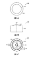
- 3A to 3C are diagrams showing the configuration of the light flux controlling member according to the first embodiment.
- 4A to 4C are diagrams showing the configuration of the light flux controlling member according to the first embodiment.
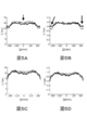
- 5A to 5D are graphs of simulation results using the light flux controlling member according to the first embodiment.
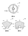
- 6A to 6C are diagrams showing the configuration of the light flux controlling member according to the second embodiment.
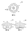
- 7A to 7C are diagrams showing the configuration of the light flux controlling member according to the third embodiment.
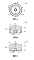
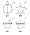
- 8A to 8D are diagrams showing the configuration of the light flux controlling member according to the fourth embodiment.
- FIGS. 9A to 9C are diagrams showing the configuration of the light flux controlling member according to the fourth embodiment.
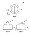
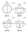
- 10A to 10D are diagrams showing the configuration of a light flux controlling member according to a modification of the fourth embodiment.
- 11A to 11C are diagrams showing the configuration of the light flux controlling member according to the fifth embodiment.
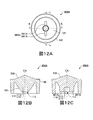
- 12A to 12C are diagrams showing the configuration of a light flux controlling member according to a modification of the fifth embodiment.
- 13A to 13C are diagrams showing the configuration of a light flux controlling member according to the sixth embodiment.
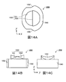
- 14A to 14C are diagrams showing the configuration of the light flux controlling member according to the seventh embodiment.
- FIGS. 15A to 15C are diagrams showing the configuration of a light flux controlling member according to a seventh embodiment.
- FIGS. 15A to 15C are diagrams showing the configuration of a light flux controlling member according to a seventh embodiment.
- FIGS. 15A to 15C are diagrams showing the configuration of a light flux controlling member according to a seventh embodiment.
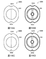
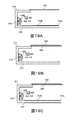
- 16A to 16D are diagrams showing the configuration of a light flux controlling member according to a modification of the seventh embodiment.
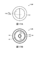
- 17A and 17B are diagrams showing the configuration of a light flux controlling member according to an eighth embodiment.
- 18A to 18C are diagrams showing the configuration of a light flux controlling member according to a modification of the eighth embodiment.
- 19A to 19C are diagrams showing the configuration of a modification of the surface light source device according to the present invention. It is sectional drawing which shows another example of the illuminating device of this invention.
- FIG. 1A is a plan view of the surface light source device 300
- FIG. 1B is a front view of the surface light source device 300
- 2A is a cross-sectional view taken along the line AA shown in FIG. 1B
- FIG. 2B is a partially enlarged cross-sectional view taken along the line BB shown in FIG. 1A.
- the surface light source device 300 includes a housing 310, two substrates 320, a plurality of light emitting devices 200, and a light emitting surface member 330 as a member to be irradiated. Have.
- the housing 310 is a rectangular parallelepiped box for housing the substrate 320 and the plurality of light emitting devices 200 therein.
- the housing 310 includes a top plate 311, a bottom plate 312 facing the top plate 311, and four side walls 313 to 316 connecting the top plate 311 and the bottom plate 312.
- a rectangular opening closed by the light emitting surface member 330 is formed (see FIG. 2B).
- the inner surface of the bottom plate 312 functions as a diffuse reflection surface 312 a that diffuses and reflects the light emitted from the light emitting device 200 toward the light emitting surface member 330.
- the housing 310 is made of, for example, a resin such as polymethyl methacrylate (PMMA) or polycarbonate (PC), or a metal such as stainless steel or aluminum.
- the two substrates 320 are rectangular flat plates for arranging the plurality of light emitting devices 200 at predetermined intervals.
- the two substrates 320 are respectively fixed to two side walls 313 and 315 facing each other (see FIG. 2A).
- the plurality of light emitting devices 200 are arranged in a line at predetermined intervals on each of the two substrates 320 (see FIG. 2A).
- Each of the plurality of light emitting devices 200 includes the light emitting element 210 and the light flux controlling member 100 (see FIG. 2B).
- the light emitting element 210 is a light source of the surface light source device 300 (and the light emitting device 200), and is fixed on the substrate 320.
- the light emitting element 210 is, for example, a light emitting diode (LED) such as a white light emitting diode.
- LED light emitting diode
- the light flux controlling member 100 controls the light distribution of the light emitted from the light emitting element 210.
- the light flux controlling member 100 is disposed on the light emitting element 210 such that the central axis CA thereof coincides with the optical axis LA of the light emitting element 210 (see FIG. 2B).
- the “optical axis of the light emitting element” means a light ray at the center of a three-dimensional light flux emitted from the light emitting element 210.
- the side of the light flux controlling member 100 opposite to the light emitting element 210 is referred to as “back side”, the side not opposite to the light emitting element 210 is referred to as “front side”.
- the central axis of the total reflection surface 120 is defined as "the central axis of the light flux controlling member”.
- the light flux control member 100 is positioned at an appropriate position on the substrate 320.
- a second light emitting portion 160 having a pair of plate-like portions 161 for emitting a part of light incident on the light flux controlling member 100 to the outside It is formed to project from (see FIG. 3C).
- the pair of plate-like portions 161 are spaced 180 degrees apart in the circumferential direction around the central axis CA of the light flux controlling member 100.
- the light flux controlling member 100 is formed by integral molding.
- the material of the light flux controlling member 100 is not particularly limited as long as it can pass light of a desired wavelength.
- the material of the light flux controlling member 100 is a light transmitting resin such as polymethyl methacrylate (PMMA), polycarbonate (PC), epoxy resin (EP), or glass.
- the surface light source device 300 of the present invention is characterized mainly in the configuration of the light flux control member 100. Therefore, the light flux controlling member 100 will be separately described in detail.
- the light emitting surface member 330 is a plate-like member having a light diffusing property, and is disposed to close an opening formed in the top plate 311 of the housing 310.
- the light emitting surface member 330 is a member to be irradiated with which the light emitted from the light emitting device 200 is irradiated.
- An inner surface (a surface facing the bottom plate 312) of the light emitting surface member 330 is a surface to be irradiated with the light emitted from the light emitting device 200.
- the light emitting surface member 330 diffuses and transmits the light emitted from the light flux controlling member 100 and the reflected light from the diffuse reflection surface 312 a.
- the light emitting surface member 330 has substantially the same size as a liquid crystal panel or the like.
- the light emitting surface member 330 is formed of a light transmitting resin such as polymethyl methacrylate (PMMA), polycarbonate (PC), polystyrene (PS), and styrene / methyl methacrylate copolymer resin (MS).
- PMMA polymethyl methacrylate
- PC polycarbonate
- PS polystyrene
- MS styrene / methyl methacrylate copolymer resin
- fine irregularities are formed on the surface of the light emitting surface member 330, or light diffusers such as beads are dispersed inside the light emitting surface member 330.
- the plurality of light emitting devices 200 are arranged such that the optical axes LA of the light emitting elements 210 are substantially parallel to the light emitting surface member 330. That is, the plurality of light emitting devices 200 are arranged such that the incident angle to light emitting surface member 330 decreases as the emission angle of light emitted from light emitting device 200 with respect to light axis LA of light emitting element 210 increases. . A part of the light emitted from each light emitting element 210 is condensed by the light flux controlling member 100 in the direction of the optical axis LA of each light emitting element 210 (narrowed angle light distribution is made).
- the plurality of light emitting devices 200 are arranged such that the light emitting surface member 330 is substantially parallel to a straight line that is orthogonal to the central axis CA of the light flux controlling member 100 and passes through the inside of the pair of plate-like portions 161 ing.
- a part of the light incident on the light flux controlling member 100 is emitted from the second emission unit 160 in the arrangement direction of the light emitting devices 200 without being reflected by the total reflection surface 120.
- the light emitted from the light flux controlling member 100 is diffusely reflected directly or by the diffuse reflecting surface 312 a, and reaches the inner surface of the light emitting surface member 330 substantially uniformly.
- the light having reached the inner surface of the light emitting surface member 330 is transmitted through the light emitting surface member 330 while being further diffused by the light emitting surface member 330.
- the brightness of the light emitting surface (the outer surface of the light emitting surface member 330) is made uniform (the luminance unevenness is small).
- FIGS. 3 and 4 are diagrams showing the configuration of the light flux controlling member 100 according to the first embodiment of the present invention.
- 3A is a plan view of the light flux controlling member 100 according to the first embodiment
- FIG. 3B is a side view of the light flux controlling member 100 according to the first embodiment
- FIGS. 3C and 4A are embodiments. It is a bottom view of light flux control member 100 concerning 1st.
- 4B is a cross-sectional view taken along the line CC shown in FIG. 4A
- FIG. 4C is a cross-sectional view taken along the line DD shown in FIG. 4A.
- the light flux controlling member 100 has an incident part 110, a total reflection surface 120, a first emitting part 130, a flange 140, a holder 150 and a second emitting part 160.
- the incident part 110 is an inner surface of the recessed part 113 formed on the back side (the light emitting element 210 side) of the light flux controlling member 100 so as to intersect the central axis CA (see FIGS. 4B and 4C).
- the incident part 110 is a rotationally symmetric surface centered on the central axis CA.
- the incident portion 110 includes an inner top surface 111 that forms the top surface of the recess 113 and a tapered inner side surface 112 that configures the side surface of the recess 113.
- the total reflection surface 120 reflects a part of the light incident from the incident part 110 toward the first emission part 130 (front side).
- the total reflection surface 120 is a surface extending from the outer edge of the bottom of the light flux controlling member 100 to the outer edge of the first emission surface 130 (more precisely, the inner edge of the flange 140) (see FIG. 4B) , And the second emission part 160 protrudes (described later).
- the total reflection surface 120 is basically a rotationally symmetric surface formed so as to surround the central axis CA, but the total reflection surface 120 does not exist in the area where the second emission part 160 protrudes.
- the diameter of the total reflection surface 120 gradually increases from the incident portion 110 side (back side) toward the first emission portion 130 side (front side).
- the generatrix (total reflection surface 120 in the cross-sectional view including central axis CA) constituting total reflection surface 120 is an arc-shaped curve convex outward (side away from central axis CA) (see FIG. 4B).
- the first emission unit 130 is a surface of the light flux controlling member 100 located on the opposite side (front side) of the incident unit 110, and is formed to intersect the central axis CA.
- the first emitting unit 130 emits the other part of the light incident from the incident unit 110 (the light incident from the incident unit 110 and directly reaching the first emitting unit 130) and the light reflected by the total reflection surface 120 to the outside Do.
- the first emission portion 130 is a rotationally symmetric surface centered on the central axis CA, and the point of intersection with the central axis CA is the point with the highest height from the back side. (See FIGS. 3B, 4B and 4C).
- the generatrix (the 1st outgoing radiation part 130 in a sectional view including central axis CA) which constitutes the 1st outgoing radiation part 130 is a circular arc shape convex to the front side.
- the flange 140 is an annular member formed to extend from the outer edge of the total reflection surface 120 and the first emission part 130 in the radial direction of the first emission part 130 (direction orthogonal to the central axis CA) See Figure 3A).
- the light flux controlling member main body including the incident portion 110, the total reflection surface 120 and the first light emitting portion 130 is joined to the holder 150 via the flange 140 (see FIG. 4B). ).
- the holder 150 supports the light flux controlling member main body and positions the light flux controlling member main body with respect to the substrate 320.
- the holder 150 is a substantially cylindrical member, and is formed in a forward tapered shape.
- a flange 140 is joined to the upper end of the holder 150.
- the second emitting unit 160 emits the other part of the light incident from the incident unit 110 (the light incident from the incident unit 110 and reaching the second emitting unit 160) to the outside. More specifically, the second emission unit 160 does not reflect a part of light having a large angle with respect to the optical axis LA of the light emitting element 210 among the light incident from the incident unit 110, without reflecting the total reflection surface 120. The light is emitted to the outside through the holder 150 at a large angle with respect to the optical axis LA of the light emitting element 210.
- the second emission part 160 has one or more plate-like parts 161 extending in the radial direction from the total reflection surface 120. In the present embodiment, the second emission part 160 has a pair of plate-like parts 161.
- the pair of plate-like portions 161 is arranged to fill the region between the total reflection surface 120 and the holder 150 in a cross section including the central axis CA (see FIG. 4C).
- the lower ends of the pair of plate-like parts 161 are formed at the same height as the opening of the recess 113 (in the direction orthogonal to the central axis CA).
- One plate-like portion 161 and the other plate-like portion 161 are spaced apart 180 degrees in the circumferential direction centering on the central axis CA. That is, the pair of plate-like parts 161 are arranged in the same plane with the central axis CA interposed therebetween.
- the pair of plate-like parts 161 divides the total reflection surface 120 into two so as to be separated by the thickness of the plate-like parts 161.
- Light distribution characteristic of luminous flux control member A simulation was performed on the distribution of brightness on the light emitting surface member 330 of the surface light source device 300 using the light flux controlling member 100 according to the present embodiment.
- a surface light source device 300 (hereinafter referred to as “in the present embodiment, the light source device 200 having the light flux controlling member 100 is fixed to four by two on two side walls 313 and 315 facing each other.
- the illuminance of the measurement surface arranged 0.5 mm apart from the light emitting surface member 330 was measured using a surface light source device.
- the measurement surface is a virtual surface that is assumed to be illuminated by the light transmitted through the light emitting surface member 330, and the illuminance distribution obtained by simulation is equivalent to the luminance distribution on the light emitting surface member 330.
- the light emitting device 200 (light flux controlling member 100) is disposed so that the pair of plate-like portions 161 is parallel to the light emitting surface member 330.
- a surface light source device having a light flux control member not having the second emission part 160 instead of the light flux control member 100 according to the present embodiment hereinafter referred to as “surface light source device of comparative example”. A similar simulation was performed.
- FIG. 5A is a graph showing the illuminance distribution on line QQ in FIG. 2A
- FIG. 5B is a graph normalized with the maximum value being 1 in the illuminance distribution of FIG. 5A
- FIG. 5C is a graph 5D is a graph showing the illuminance distribution on the RR line in FIG. 5
- FIG. 5D is a graph in which the maximum value is normalized to 1 in the illuminance distribution of FIG. 5C.
- black lines indicate the results of the surface light source device 300 of the present embodiment
- gray lines indicate the results of the surface light source device of the comparative example.
- the horizontal axis indicates the position (D; unit mm) in the major axis direction of the lighting device 300 when the center in the major axis direction of the lighting device 300 is “0”.
- the vertical axis indicates the illuminance (L; unit lux).
- the illuminance at the central portion between the light sources is lower than that of the surface light source device of the comparative example (see the arrow in FIG. 5A).
- the illuminance of the region between the light sources and in the vicinity of the light source is higher than that of the surface light source device of the comparative example (see arrow in FIG. 5B). This is because the light incident from the entrance section 110 into the light flux control member 100 is not only in the first exit section 130 but also in the arrangement direction of the light emitting elements 210 via the second exit section 160 (a pair of plate-like sections 161).
- the contrast of the illuminance is weaker than in the surface light source device of the comparative example (the uneven brightness is smaller).
- the light emitting device 200 having the light flux controlling member 100 according to the present embodiment emits light in the lateral direction not only from the first emitting unit 130 but also from the second emitting unit 160. For this reason, in the surface light source device 300 of the present embodiment, a dark portion is unlikely to occur in the region between the light emitting devices 200 of the light emitting surface member 330. Therefore, the surface light source device 300 has less luminance unevenness.
- the surface light source device and the light emitting device according to the second embodiment of the present invention relate to the first embodiment in that the light flux controlling member 500 according to the second embodiment is provided instead of the light flux controlling member 100 according to the first embodiment. It differs from the surface light source device 300 and the light emitting device 200. Thus, in the present embodiment, only the light flux controlling member 500 according to the second embodiment will be described.
- the light flux controlling member 500 according to the second embodiment differs from the light flux controlling member 100 according to the first embodiment only in the shape of the first light emitting portion 530. So, about the component same as the light beam control member 100 which concerns on Embodiment 1, the same code
- FIG. 6 is a view showing the configuration of the light flux controlling member 500 according to the second embodiment.
- 6A is a plan view of the light flux controlling member 500 according to the second embodiment
- FIG. 6B is a left side view of the light flux controlling member 500 according to the second embodiment
- FIG. 6C is a plan view of the light flux controlling member 500 according to the second embodiment. It is a right side view of light flux control member 500 which concerns.
- the direction of the central axis of the light flux controlling member 500 is taken as the z-axis direction
- the two directions orthogonal to the z-axis and orthogonal to each other are taken as the x-axis direction and the y-axis direction.
- the light flux controlling member 500 is disposed such that the yz plane is substantially parallel to the light emitting surface member 330.
- the light flux controlling member 500 has an incident part 110, a total reflection surface 120, a first emitting part 530, a flange 140 and a holder 150.
- the incident portion 110 and the total reflection surface 120 are not visible because they are surrounded by the holder 150.
- the shape of the first emission part 530 is different at a boundary passing through the central axis CA and parallel to the yz plane, and the first emission part 530 is the first It has an emitting surface 531 and a second emitting surface 532.
- the first exit surface 531 is a part of a rotationally symmetric surface centered on the central axis CA, and the point of intersection with the central axis CA is the highest point from the rear side (see FIG. 6B).
- the generatrix (the first exit surface 531 in the cross-sectional view including the central axis CA) constituting the first exit surface 531 is an arc-shaped curve convex to the front side.
- the second emission surface 532 has a substantially cylindrical shape having a curvature in the x-axis direction but no curvature in the y-axis direction (see FIG. 6C). Therefore, the second exit surface 532 condenses the light in the x-axis direction, but spreads and emits the light in the y-axis direction.
- the light flux controlling member 500 is disposed such that the yz plane is substantially parallel to the light emitting surface member 330 and the second light emitting surface 532 is on the light emitting surface member 330 side.
- the light flux controlling member 500 condenses light in the x axis direction and the y axis direction on the first exit surface 531.
- the light can be condensed only in the x-axis direction and the light can be spread in the y-axis direction on the second emission surface 532. Therefore, in the surface light source device including the light flux controlling member 500, while suppressing the generation of the dark part in the region between the two light flux controlling members 500 of the light emitting surface, the light is made to reach far and the luminance unevenness of the light emitting surface is further increased. It can be reduced.
- the surface light source device and the light emitting device according to the third embodiment of the present invention are the same as the first embodiment in that the light flux controlling member 600 according to the third embodiment is provided instead of the light flux controlling member 100 according to the first embodiment. It differs from the surface light source device 300 and the light emitting device 200 which concern. Thus, in the present embodiment, only the light flux controlling member 600 according to the third embodiment will be described.
- the light flux controlling member 600 according to the third embodiment differs from the light flux controlling member 100 according to the first embodiment only in the shape of the second light emitting portion 660. So, about the component same as the light beam control member 100 which concerns on Embodiment 1, the same code
- FIG. 7A is a bottom view of the light flux controlling member 600 according to the third embodiment
- FIG. 7B is a cross-sectional view taken along the line EE shown in FIG. 7A
- FIG. 7C is an F- cross shown in FIG. It is a sectional view of the F line.
- the light flux controlling member 600 has an incident part 110, a total reflection surface 120, a first emission part 130, a flange 140, a holder 150 and a second emission part 660.
- the second light emitting portion 660 has a pair of plate-like portions 661 radially extending from the total reflection surface 120.
- the pair of plate-like portions 661 is arranged to fill the region between the total reflection surface 120 and the holder 150 in a cross section including the central axis CA (see FIG. 7C).
- the lower ends of the pair of plate-like portions 661 are formed at the same height as the opening of the recess 113.
- One plate-shaped portion 661 and the other plate-shaped portion 661 are disposed apart from each other by 180 degrees in the circumferential direction centering on the central axis CA.
- the pair of plate-like portions 661 are formed such that the plate thickness gradually increases from the central axis CA toward the outer edge in a cross section orthogonal to the central axis CA.
- the light flux controlling member 600 according to the present embodiment has the same effect as the light flux controlling member 100 according to the first embodiment. Further, by forming the plate-like portion 661 so that the width of the region on the total reflection surface 120 to which the second emission portion 660 is projected changes depending on the height from the back surface of the light flux controlling member 600 The distribution of the light for controlling the generation of the dark part in the area between the two light flux controlling members 600 and the light for reaching the distant place can be appropriately adjusted.
- Embodiment 4 of the present invention are different from Embodiment 1 in that light flux controlling member 700 according to Embodiment 4 is provided instead of light flux controlling member 100 according to Embodiment 1. It differs from the surface light source device 300 and the light emitting device 200 which concern. Thus, in the present embodiment, only the light flux controlling member 700 according to the fourth embodiment will be described.
- the light flux controlling member 700 according to the fourth embodiment is different from the light flux controlling member 500 according to the second embodiment only in the presence or absence of the holder 150 and the shape of the second light emitting unit 760. So, about the component same as the light beam control member 500 which concerns on Embodiment 2, the same code
- FIGS. 8 and 9 are diagrams showing the configuration of a light flux controlling member 700 according to the fourth embodiment.
- 8A is a plan view of the light flux controlling member 700 according to the fourth embodiment
- FIG. 8B is a front view of the light flux controlling member 700 according to the fourth embodiment
- FIG. 8C relates to the fourth embodiment.
- FIG. 8D is a left side view of the light flux controlling member 700
- FIG. 8D is a right side view of the light flux controlling member 700 according to the fourth embodiment.
- FIG. 9A is a bottom view of light flux controlling member 700 according to the fourth embodiment
- FIG. 9B is a cross-sectional view taken along the line GG shown in FIG. 9A
- FIG. 9C is a cross sectional view of H- shown in FIG. It is a sectional view of H line.
- the light flux controlling member 700 has an incident part 110, a total reflection surface 120, a first emission part 530 and a second emission part 760.
- the second light emitting portion 760 includes a pair of plate-like portions 761 extending in the radial direction from the total reflection surface 120.
- the pair of plate-like portions 761 are disposed apart by 180 degrees with respect to the central axis CA. Further, the outer edge portions of the pair of plate-like portions 761 reach the side surfaces of the flange 140.
- the light flux controlling member 700 according to the present embodiment can be manufactured at lower cost because the holder 150 is not formed in addition to the same effect as the light flux controlling member 100 according to the first embodiment.
- the flange 140 can be thinned. That is, in the case of integrally molding the light flux controlling member 100 according to the first embodiment having the holder 150, it is necessary to thicken the flange 140 to some extent in order to supply the resin to the holder 150, but the holder 150 is not provided.
- the flange 140 since the resin is not supplied to the holder 150, the flange 140 can be thinned. Therefore, as shown in FIG. 10 (plan view), FIG. 10B (front view), FIG. 10C (left side view), and FIG. 10D (right side view), in the light flux controlling member 700A according to the present embodiment, The flange 140A may be thinned. By doing this, the total reflection surface 120 can be made larger, and light can be emitted farther.
- the surface light source device and the light emitting device according to the fifth embodiment of the present invention are the same as the first embodiment in that the light flux controlling member 800 according to the fifth embodiment is provided instead of the light flux controlling member 100 according to the first embodiment. It differs from the surface light source device 300 and the light emitting device 200 which concern. Therefore, in the present embodiment, only the light flux controlling member 800 according to the fifth embodiment will be described.
- the light flux controlling member 800 according to the fifth embodiment differs from the light flux controlling member 500 according to the second embodiment only in the shape and / or the position of the second light emitting portion 860. So, about the component same as the light beam control member 500 which concerns on Embodiment 2, the same code
- FIG. 11 is a view showing the configuration of a light flux controlling member 800 according to the fifth embodiment.
- 11A is a bottom view of light flux controlling member 800 according to the fifth embodiment
- FIG. 11B is a cross sectional view taken along line II shown in FIG. 11A
- FIG. 11C is a cross section taken along line J- of FIG. It is sectional drawing of J line.
- the light flux controlling member 800 has an incident part 110, a total reflection surface 120, a first emission part 530, a holder 150 and a second emission part 860.
- the second light emitting portion 860 has a pair of plate-like portions 861 extending in the radial direction from the total reflection surface 120.
- the pair of plate-like portions 861 is arranged to fill the region between the total reflection surface 120 and the holder 150 in a cross section including the central axis CA (see FIG. 11C). Further, the lower ends of the pair of plate-like portions 861 are half the height of the total reflection surface 120 (the same height as the inner top surface 111) in the cross section including the central axis CA.
- one plate-shaped portion 861 and the other plate-shaped portion 861 are disposed apart from each other by 180 degrees in the circumferential direction about the central axis CA.
- the shape and position of the second emission part 860 are not limited to the aspect shown in FIG.
- FIG. 12A bottom view
- FIG. 12B cross-sectional view along the line KK
- FIG. 12C cross-sectional view along the line LL
- the second emission part 860A may be formed only in the vicinity of the incident part 110.
- the second emission part 860A has a pair of plate-like parts 861A.
- the lower ends of the pair of plate-like portions 861A are formed at the same height as the opening of the recess 113, and the upper ends of the pair of plate-like portions 861A are half the height of the total reflection surface 120 in the cross section including the central axis CA. It has reached.
- the light flux controlling members 800 and 800A according to the present embodiment have the same effects as the light flux controlling member 100 according to the first embodiment. Further, the generation of a dark portion in the area between the two light flux controlling members 800 on the light emitting surface is controlled by the position where the second emission section 860 protrudes and the shape of the connection area between the second emission section 860 and the total reflection surface 120. It is possible to appropriately adjust the distribution of the light for the purpose and the light for reaching the distant place.
- the surface light source device and the light emitting device according to the sixth embodiment of the present invention are different from the first embodiment in that the light flux controlling member 900 according to the sixth embodiment is provided instead of the light flux controlling member 100 according to the first embodiment. It differs from the surface light source device 300 and the light emitting device 200. Therefore, in the present embodiment, only the light flux controlling member 900 according to the sixth embodiment will be described.
- the light flux controlling member 900 according to the sixth embodiment differs from the light flux controlling member 500 according to the second embodiment only in the shapes of the flange 940 and the holder 950. So, about the component same as the light beam control member 500 which concerns on Embodiment 2, the same code
- FIG. 13 is a view showing the configuration of a light flux controlling member 900 according to the sixth embodiment.
- 13A is a bottom view of light flux controlling member 900 according to the sixth embodiment
- FIG. 13B is a cross-sectional view of line MM shown in FIG. 13A
- FIG. 13C is an N ⁇ line shown in FIG. It is sectional drawing of N line.
- the light flux controlling member 900 has an incident part 110, a total reflection surface 120, a first emission part 530, a flange 940, a holder 950 and a second emission part 160.
- a pair of convex streaks 941 are formed on the side surfaces of the flange 940 and the holder 950 in the light flux controlling member 900 according to the sixth embodiment.
- the pair of ridges 941 are spaced apart by 180 degrees in the circumferential direction about the central axis CA. Further, the pair of convex streaks 941 are arranged in the same direction as the extending direction of the pair of plate-like portions 161 from the central axis CA.
- the pair of convex streaks 941 have a semicircular cross-sectional shape orthogonal to the central axis CA, and condenses the light propagating in the plate-like portion 161 and emits the light to the outside.
- the light flux controlling member 900 according to the present embodiment has the same effect as the light flux controlling member 100 according to the first embodiment. Further, since the pair of plate-like portions 161 and the pair of convex streaks 941 having a semicircular cross-sectional shape are arranged in the same direction, the light propagating in the pair of plate-like portions 161 is collected while being collected. It can be emitted outside.
- the surface light source device and the light emitting device according to the seventh embodiment of the present invention relate to the first embodiment in that the light flux controlling member 1000 of the seventh embodiment is provided instead of the light flux controlling member 100 according to the first embodiment. It differs from the surface light source device 300 and the light emitting device 200. Therefore, in the present embodiment, only the light flux controlling member 1000 according to the seventh embodiment will be described.
- FIGS. 14 and 15 are views showing the configuration of a light flux controlling member 1000 according to a seventh embodiment.
- 14A is a plan view of the light flux controlling member 1000 according to the seventh embodiment
- FIG. 14B is a left side view of the light flux controlling member 1000 according to the seventh embodiment
- FIG. 14C is a plan view according to the seventh embodiment. It is a right side view of light flux control member 1000 which concerns.
- FIG. 15A is a bottom view of light flux controlling member 1000 according to the seventh embodiment
- FIG. 15B is a cross-sectional view of OO line shown in FIG. 15A
- FIG. 15C is a P- view shown in FIG. It is a sectional view of P line.
- the direction of the central axis of the light flux controlling member 1000 is taken as the z-axis direction, and the two directions orthogonal to the z-axis and orthogonal to each other are taken as the x-axis direction and the y-axis direction.
- the light flux controlling member 1000 is disposed such that the yz plane is substantially parallel to the light emitting surface member 330.
- the light flux controlling member 1000 according to the seventh embodiment comprises an incident part 110, a total reflection surface 120, a first emission part 1030, a flange 1040, a holder 1050 and a second emission part 860.
- the light flux controlling member 1000 according to the seventh embodiment differs from the light flux controlling member 100 according to the first embodiment in the shapes of the first light emitting portion 1030, the flange 1040 and the holder 1050. Accordingly, the shapes of the first emission part 1030, the flange 1040 and the holder 1050 will be described with reference to FIGS. 14 and 15.
- symbol is attached
- the first emission unit 1030 has a first emission surface 531 and a second emission surface 1032.
- the second emission surface 1032 is shaped like a bowl, and has curvatures in each of the x-axis direction and the y-axis direction.
- the center of curvature in the x-axis direction is below the second exit surface 1032, and the center of curvature in the y-axis direction is above the second exit surface 1032.
- a pair of concave streaks 1052 is formed on the side surface of the flange 1040 and the holder 1050.
- the pair of concave streaks 1052 are spaced apart by 180 degrees in the circumferential direction about the central axis CA.
- the pair of concave streaks 1052 is disposed in the same direction as the extending direction of the pair of plate-like portions 161 from the central axis CA.
- the pair of concave streaks 1052 are formed such that one surface is inclined at a predetermined angle with respect to the xz plane, and the light propagating in the plate portion 161 is refracted in a predetermined direction and emitted to the outside Let
- the shape of the grooved part 1052 is not limited to the aspect shown by FIG. 14 and FIG.
- the concave streak portion 1052A has a semicircular cross-sectional shape orthogonal to the central axis CA. It may be In this case, the light propagating in the plate-like portion 161 is emitted to the outside while being spread at the concave streak portion 1052.
- the concave streak portion 1052B has a triangular cross section perpendicular to the central axis CA. It may be.
- the light propagated in the plate-like portion 161 is reflected by one of the surfaces of the concave streak portion 1052 and emitted from the side surface of the holder 150 to the outside.
- the light flux controlling members 1000, 1000A, 1000B according to the present embodiment have the same effect as the light flux controlling member 100 according to the first embodiment, and light propagating in the pair of plate-like portions 161 is directed in a specific direction. It can be emitted outside while distributing light.
- the surface light source device and the light emitting device according to the eighth embodiment of the present invention are the same as the first embodiment in that the light flux controlling member 1100 according to the eighth embodiment is provided instead of the light flux controlling member 100 according to the first embodiment. It differs from the surface light source device 300 and the light emitting device 200 which concern. Therefore, in the present embodiment, only the light flux controlling member 1100 according to the eighth embodiment will be described.
- the light flux controlling member 1100 according to the eighth embodiment differs from the light flux controlling member 1000 according to the seventh embodiment only in the shape of the flange 1140 and the position of the second light emitting unit 160. Therefore, the same components as those of the light flux controlling member 1000 according to the seventh embodiment are designated by the same reference numerals, and the description thereof is omitted.
- FIG. 17 is a view showing the configuration of a light flux controlling member 1100 according to the eighth embodiment.
- FIG. 17A is a plan view of a light flux controlling member 1100 according to the eighth embodiment
- FIG. 17B is a bottom view of the light flux controlling member 1100 according to the eighth embodiment.
- the light flux controlling member 1100 has an incident part 110, a total reflection surface 120, a first emission part 1030, a flange 1140, a holder 150 and a second emission part 160.
- the flange 1140 is formed in a substantially circular shape in plan view.
- the second emission unit 160 also has a pair of plate-like parts 161. One plate-like portion 161 and the other plate-like portion 161 are arranged at intervals of 150 degrees in the circumferential direction around the central axis CA (see FIG. 17B).
- the position and number of the plate-like part 161 are not limited to the aspect shown by FIG.
- one plate-like portion 161 and the other plate-like portion 161 are circumferentially centered on the central axis CA. It may be arranged at intervals of 120 degrees.
- one plate-like portion 161 and the other plate-like portion 161 are circumferentially centered on the central axis CA. It may be disposed at an interval of 60 degrees.
- FIG. 18C bottom view
- one plate-shaped portion 161 and the other plate-shaped portion 161 may overlap. That is, the second emission unit 160 may have a single plate-like portion 161.
- the light flux controlling members 1100, 1100A, 1100B, and 1100C according to the present embodiment have the same effects as the light flux controlling member 100 according to the first embodiment.
- the surface light source device in which the entire inner surface of the bottom plate 312 is the diffuse reflection surface 312a has been described.
- FIG. 19A cross sectional view
- the specular reflection surface 312 b may be formed in the area near the member.
- a light emission surface A prism sheet 340 may be disposed on the inner surface of the member 330.
- a plurality of convex stripes having a triangular cross section are formed along the optical axis LA direction of the light emitting element 210 so as to face the light emitting surface member 330.
- the ridges of the prism sheet 340 function as a total reflection prism, and reflect the reached light to the side of the bottom plate 312, thereby guiding the light emitted from the light flux controlling member to a further distance.
- the regular reflection surface 312b and the prism sheet 340 may be disposed.
- the lighting installation (surface light source device 300) which light passes through to-be-irradiated member (light-emitting surface member 330) arrange
- a lighting device is suitable as a backlight of a liquid crystal display device, a ceiling light, an internally illuminated signboard, or the like.
- the irradiated member may not transmit light.
- light may be emitted to an irradiated member that does not transmit light (for example, a wall surface, a signboard with a picture or characters, etc.).
- FIG. 20 shows an irradiated member that does not transmit light.
- the light emitting device 200 is disposed such that the optical axis LA of the light emitting element 210 intersects with the light receiving surface of the light receiving member 350 at an acute angle.
- the light flux controlling member 100 is disposed such that the plane including the second light emitting portion 160 and the light receiving surface of the light receiving member 350 intersect at an acute angle, whereby the light emitted from the second light emitting portion 160 is the light emitting device 200. It can be turned into light that illuminates the area that is likely to be the dark part between them.
- a lighting device is suitable as wall light, an externally illuminated signboard, and the like.
- the light flux controlling member, the light emitting device, and the lighting device of the present invention are useful, for example, for a backlight of a liquid crystal display device, a surface lighting device, and the like. Further, the light flux controlling member and the light emitting device of the present invention can be applied to, for example, wall surface illumination and downlight.
- Reference Signs List 100 light flux control member 110 incident portion 111 inner top surface 112 inner side surface 113 concave portion 120 total reflection surface 130 first emission portion 140 flange 150 holder 160 second emission portion 161 plate-like portion 200 light emitting device 210 light emitting element 300 surface light source device 310 housing Body 311 top plate 312 bottom plate 312a diffuse reflection surface 313 to 316 side wall 320 substrate 330 light emitting surface member CA central axis of luminous flux control member LA optical axis of light emitting element
Landscapes
- Engineering & Computer Science (AREA)
- General Engineering & Computer Science (AREA)
- Physics & Mathematics (AREA)
- General Physics & Mathematics (AREA)
- Optics & Photonics (AREA)
- Multimedia (AREA)
- Planar Illumination Modules (AREA)
- Lenses (AREA)
- Liquid Crystal (AREA)
Priority Applications (2)
| Application Number | Priority Date | Filing Date | Title |
|---|---|---|---|
| CN201380031259.6A CN104364696B (zh) | 2012-06-22 | 2013-06-11 | 光束控制部件、发光装置、照明装置及显示装置 |
| US14/409,631 US9568163B2 (en) | 2012-06-22 | 2013-06-11 | Luminous flux control member, light emitting apparatus, illuminating apparatus, and display apparatus |
Applications Claiming Priority (2)
| Application Number | Priority Date | Filing Date | Title |
|---|---|---|---|
| JP2012-140930 | 2012-06-22 | ||
| JP2012140930A JP6085105B2 (ja) | 2012-06-22 | 2012-06-22 | 光束制御部材、発光装置、照明装置および表示装置 |
Publications (1)
| Publication Number | Publication Date |
|---|---|
| WO2013190801A1 true WO2013190801A1 (fr) | 2013-12-27 |
Family
ID=49768416
Family Applications (1)
| Application Number | Title | Priority Date | Filing Date |
|---|---|---|---|
| PCT/JP2013/003649 Ceased WO2013190801A1 (fr) | 2012-06-22 | 2013-06-11 | Élément de commande de flux lumineux, appareil électroluminescent, appareil d'éclairage et appareil d'affichage |
Country Status (4)
| Country | Link |
|---|---|
| US (1) | US9568163B2 (fr) |
| JP (1) | JP6085105B2 (fr) |
| CN (1) | CN104364696B (fr) |
| WO (1) | WO2013190801A1 (fr) |
Cited By (1)
| Publication number | Priority date | Publication date | Assignee | Title |
|---|---|---|---|---|
| WO2017150456A1 (fr) * | 2016-03-02 | 2017-09-08 | 三菱電機株式会社 | Dispositif d'éclairage |
Families Citing this family (4)
| Publication number | Priority date | Publication date | Assignee | Title |
|---|---|---|---|---|
| KR102174249B1 (ko) * | 2014-01-17 | 2020-11-04 | 엘지이노텍 주식회사 | 광속제어부재, 발광장치 및 표시장치 |
| KR20170064664A (ko) * | 2015-12-02 | 2017-06-12 | 엘지이노텍 주식회사 | 조명장치 및 이를 포함하는 차량용 램프 |
| JP2018125245A (ja) * | 2017-02-03 | 2018-08-09 | 株式会社エンプラス | 面光源装置および表示装置 |
| DE102018208185A1 (de) * | 2018-05-24 | 2019-11-28 | Robert Bosch Gmbh | Optisches Element zur Lichtkonzentration und Herstellungsverfahren für ein optisches Element zur Lichtkonzentration |
Citations (2)
| Publication number | Priority date | Publication date | Assignee | Title |
|---|---|---|---|---|
| JP2004281605A (ja) * | 2003-03-14 | 2004-10-07 | Toyoda Gosei Co Ltd | Ledパッケージ |
| JP2011222380A (ja) * | 2010-04-13 | 2011-11-04 | Enplas Corp | 光束制御部材、発光装置、及び照明装置 |
Family Cites Families (7)
| Publication number | Priority date | Publication date | Assignee | Title |
|---|---|---|---|---|
| US5381309A (en) * | 1993-09-30 | 1995-01-10 | Honeywell Inc. | Backlit display with enhanced viewing properties |
| JP4182600B2 (ja) * | 1999-08-23 | 2008-11-19 | 市光工業株式会社 | Led光源を用いた車両用灯具 |
| JP4747726B2 (ja) | 2004-09-09 | 2011-08-17 | 豊田合成株式会社 | 発光装置 |
| CN101004515A (zh) * | 2006-01-21 | 2007-07-25 | 鸿富锦精密工业(深圳)有限公司 | 直下式背光模组 |
| JP2009289506A (ja) * | 2008-05-28 | 2009-12-10 | Harison Toshiba Lighting Corp | 点光源を備えた両面発光装置およびそれを備えた表示装置 |
| JP5719104B2 (ja) * | 2009-08-24 | 2015-05-13 | 株式会社エンプラス | 光束制御部材、発光装置、面光源装置、及び表示装置 |
| KR20120131360A (ko) * | 2011-05-25 | 2012-12-05 | 삼성전자주식회사 | 면조명장치 및 이를 구비한 액정표시장치 |
-
2012
- 2012-06-22 JP JP2012140930A patent/JP6085105B2/ja not_active Expired - Fee Related
-
2013
- 2013-06-11 WO PCT/JP2013/003649 patent/WO2013190801A1/fr not_active Ceased
- 2013-06-11 CN CN201380031259.6A patent/CN104364696B/zh not_active Expired - Fee Related
- 2013-06-11 US US14/409,631 patent/US9568163B2/en not_active Expired - Fee Related
Patent Citations (2)
| Publication number | Priority date | Publication date | Assignee | Title |
|---|---|---|---|---|
| JP2004281605A (ja) * | 2003-03-14 | 2004-10-07 | Toyoda Gosei Co Ltd | Ledパッケージ |
| JP2011222380A (ja) * | 2010-04-13 | 2011-11-04 | Enplas Corp | 光束制御部材、発光装置、及び照明装置 |
Cited By (2)
| Publication number | Priority date | Publication date | Assignee | Title |
|---|---|---|---|---|
| WO2017150456A1 (fr) * | 2016-03-02 | 2017-09-08 | 三菱電機株式会社 | Dispositif d'éclairage |
| JPWO2017150456A1 (ja) * | 2016-03-02 | 2018-12-06 | 三菱電機株式会社 | 照明装置 |
Also Published As
| Publication number | Publication date |
|---|---|
| JP2014006331A (ja) | 2014-01-16 |
| CN104364696A (zh) | 2015-02-18 |
| US20150176801A1 (en) | 2015-06-25 |
| JP6085105B2 (ja) | 2017-02-22 |
| US9568163B2 (en) | 2017-02-14 |
| CN104364696B (zh) | 2017-06-23 |
Similar Documents
| Publication | Publication Date | Title |
|---|---|---|
| JP5957364B2 (ja) | 光束制御部材、発光装置、面光源装置および表示装置 | |
| JP5050149B1 (ja) | 照明装置 | |
| JP6356997B2 (ja) | 光束制御部材、発光装置、面光源装置および表示装置 | |
| US10393343B2 (en) | Light flux control member, light-emitting device, and area light source device | |
| JP6629601B2 (ja) | 光束制御部材、発光装置、面光源装置および表示装置 | |
| JP6310285B2 (ja) | 発光装置、面光源装置および表示装置 | |
| JP6682229B2 (ja) | 光束制御部材、発光装置、面光源装置および表示装置 | |
| JP6214151B2 (ja) | 照明装置 | |
| WO2013190801A1 (fr) | Élément de commande de flux lumineux, appareil électroluminescent, appareil d'éclairage et appareil d'affichage | |
| JP6316494B1 (ja) | 面光源装置および表示装置 | |
| JP6290040B2 (ja) | 光束制御部材、発光装置および照明装置 | |
| JP6437252B2 (ja) | 光束制御部材、発光装置および照明装置 | |
| JP2013020716A (ja) | 光束制御部材および発光装置 | |
| JP6748424B2 (ja) | 発光装置、面光源装置および表示装置 | |
| JP6067696B2 (ja) | 光束制御部材、発光装置、照明装置および表示装置 | |
| JP6983116B2 (ja) | 面光源装置および表示装置 | |
| WO2016194798A1 (fr) | Dispositif de source de lumière plane et dispositif d'affichage à cristaux liquides | |
| US20200348566A1 (en) | Light bundle control member, light emitting device, area-light source device, and display device | |
| WO2018135407A1 (fr) | Élément de commande de flux lumineux, dispositif électroluminescent, dispositif de source lumineuse plat et dispositif d'affichage | |
| JP6345539B2 (ja) | 光束制御部材および発光装置 | |
| KR101824688B1 (ko) | 엘이디의 확산커버 및 이를 포함하는 조명장치 | |
| JP2019216026A (ja) | 面光源装置および表示装置 | |
| WO2019097985A1 (fr) | Dispositif de source de lumière plane et dispositif d'affichage | |
| JP2020056868A (ja) | 光束制御部材、発光装置、面光源装置および表示装置 |
Legal Events
| Date | Code | Title | Description |
|---|---|---|---|
| 121 | Ep: the epo has been informed by wipo that ep was designated in this application |
Ref document number: 13806940 Country of ref document: EP Kind code of ref document: A1 |
|
| WWE | Wipo information: entry into national phase |
Ref document number: 14409631 Country of ref document: US |
|
| NENP | Non-entry into the national phase |
Ref country code: DE |
|
| 122 | Ep: pct application non-entry in european phase |
Ref document number: 13806940 Country of ref document: EP Kind code of ref document: A1 |